EP2418463A2 - Elektronisches Datenblatt eines Einzelwandlers - Google Patents
Elektronisches Datenblatt eines Einzelwandlers Download PDFInfo
- Publication number
- EP2418463A2 EP2418463A2 EP10172308A EP10172308A EP2418463A2 EP 2418463 A2 EP2418463 A2 EP 2418463A2 EP 10172308 A EP10172308 A EP 10172308A EP 10172308 A EP10172308 A EP 10172308A EP 2418463 A2 EP2418463 A2 EP 2418463A2
- Authority
- EP
- European Patent Office
- Prior art keywords
- transducers
- transducer
- information
- stored
- memory component
- Prior art date
- Legal status (The legal status is an assumption and is not a legal conclusion. Google has not performed a legal analysis and makes no representation as to the accuracy of the status listed.)
- Withdrawn
Links
- 238000000034 method Methods 0.000 claims description 28
- 230000001419 dependent effect Effects 0.000 claims 2
- 230000008569 process Effects 0.000 description 18
- 230000035945 sensitivity Effects 0.000 description 7
- 238000010586 diagram Methods 0.000 description 6
- 238000005259 measurement Methods 0.000 description 6
- 230000001133 acceleration Effects 0.000 description 4
- 238000004364 calculation method Methods 0.000 description 2
- 230000008878 coupling Effects 0.000 description 2
- 238000010168 coupling process Methods 0.000 description 2
- 238000005859 coupling reaction Methods 0.000 description 2
- 230000006870 function Effects 0.000 description 2
- 230000007175 bidirectional communication Effects 0.000 description 1
- 239000003990 capacitor Substances 0.000 description 1
- 230000006854 communication Effects 0.000 description 1
- 125000004122 cyclic group Chemical group 0.000 description 1
- 230000008676 import Effects 0.000 description 1
- 238000002372 labelling Methods 0.000 description 1
- 238000012986 modification Methods 0.000 description 1
- 230000004048 modification Effects 0.000 description 1
- 238000012545 processing Methods 0.000 description 1
- 230000011664 signaling Effects 0.000 description 1
- 238000012546 transfer Methods 0.000 description 1
- 238000010200 validation analysis Methods 0.000 description 1
Images


Classifications
-
- G—PHYSICS
- G01—MEASURING; TESTING
- G01D—MEASURING NOT SPECIALLY ADAPTED FOR A SPECIFIC VARIABLE; ARRANGEMENTS FOR MEASURING TWO OR MORE VARIABLES NOT COVERED IN A SINGLE OTHER SUBCLASS; TARIFF METERING APPARATUS; MEASURING OR TESTING NOT OTHERWISE PROVIDED FOR
- G01D18/00—Testing or calibrating apparatus or arrangements provided for in groups G01D1/00 - G01D15/00
- G01D18/008—Testing or calibrating apparatus or arrangements provided for in groups G01D1/00 - G01D15/00 with calibration coefficients stored in memory
-
- G—PHYSICS
- G01—MEASURING; TESTING
- G01D—MEASURING NOT SPECIALLY ADAPTED FOR A SPECIFIC VARIABLE; ARRANGEMENTS FOR MEASURING TWO OR MORE VARIABLES NOT COVERED IN A SINGLE OTHER SUBCLASS; TARIFF METERING APPARATUS; MEASURING OR TESTING NOT OTHERWISE PROVIDED FOR
- G01D21/00—Measuring or testing not otherwise provided for
-
- G—PHYSICS
- G01—MEASURING; TESTING
- G01D—MEASURING NOT SPECIALLY ADAPTED FOR A SPECIFIC VARIABLE; ARRANGEMENTS FOR MEASURING TWO OR MORE VARIABLES NOT COVERED IN A SINGLE OTHER SUBCLASS; TARIFF METERING APPARATUS; MEASURING OR TESTING NOT OTHERWISE PROVIDED FOR
- G01D21/00—Measuring or testing not otherwise provided for
- G01D21/02—Measuring two or more variables by means not covered by a single other subclass
-
- G—PHYSICS
- G01—MEASURING; TESTING
- G01D—MEASURING NOT SPECIALLY ADAPTED FOR A SPECIFIC VARIABLE; ARRANGEMENTS FOR MEASURING TWO OR MORE VARIABLES NOT COVERED IN A SINGLE OTHER SUBCLASS; TARIFF METERING APPARATUS; MEASURING OR TESTING NOT OTHERWISE PROVIDED FOR
- G01D3/00—Indicating or recording apparatus with provision for the special purposes referred to in the subgroups
- G01D3/02—Indicating or recording apparatus with provision for the special purposes referred to in the subgroups with provision for altering or correcting the law of variation
- G01D3/022—Indicating or recording apparatus with provision for the special purposes referred to in the subgroups with provision for altering or correcting the law of variation having an ideal characteristic, map or correction data stored in a digital memory
Definitions
- the present disclosure relates to an electronic data sheet that stores information about multiple transducers or multiple channels in a single memory.
- a transducer electronic data sheet stores transducer information, such as calibration data, identification information, and manufacturer information.
- TEDS formats are standardized and defined in the IEEE 1451 set of smart transducer interface standards.
- the TEDS is stored in a memory device attached to a transducer and contains the information needed by a measurement instrument or control system to interface with the transducer.
- each transducer has its own memory device, and that particular memory device only stores information pertaining to that transducer.
- a memory component directly coupled to a transducer can store not only data sheet information for that particular transducer but data sheet information for other transducers in the system.
- Each transducer in the system is assigned a unique index, and the data stored in the memory are indexed in order to distinguish the data corresponding to a particular transducer.
- the transducers do not have to be of the same type.
- Information stored in the memory can include, but is not limited to, identification information and calibration data.
- a processor reads the information from the memory and applies the information to measured data acquired by the transducers.
- a system comprising: a first transducer coupled to a memory component, wherein information about the first transducer is stored in the memory component; a second transducer, wherein information about the second transducer is stored in the memory component; a processor coupled among the first transducer, the second transducer, and the memory component, wherein the processor is configured to: download the stored information from the memory component; receive measured data from the first transducer and the second transducer; apply the stored information to the received measured data.
- the system further comprises one or more additional transducers, wherein additional information about the one or more additional transducers are stored in the memory component, and further wherein the processor is further coupled to and receives additional measured data from the one or more additional transducers.
- the first transducer and the second transducer may be different types of transducers. Conveniently, each transducer is assigned an index, and each piece of stored information that applies only to a particular transducer is correspondingly indexed.
- the memory component may be a non-volatile read-only memory.
- the invention provides an apparatus, comprising: a first transducer; a storage means coupled to the first transducer, wherein the storage means stores calibration information about the first transducer and at least one other transducer.
- the storage means may further store identification and location information about the first transducer and the at least one other transducer.
- the first transducer and the at least one other transducer may be accelerometers, and storage means may be a non-volatile read-only memory.
- the stored calibration information is indexed to uniquely identify a corresponding transducer to which the stored calibration information applies.
- the apparatus may further comprise a processor coupled to the first transducer, the storage means, and the at least one other transducer, and the processor may read and appropriately apply the indexed stored calibration information to measured data received from the first transducer and the at least one other transducer.
- the invention provides a method of electronically storing calibration data, comprising: calibrating a plurality of transducers; storing identification and calibration information for each of the plurality of transducers to a memory component, wherein the memory component is coupled to one of the plurality of transducers.
- the method may further comprise assigning indices to the plurality of transducers, wherein at least a first portion of the stored identification and calibration information is linked to particular transducers through the indices and second portion of the stored identification and calibration information applies to all of the plurality of transducers.
- At least one of the plurality of transducers may be of a different type than the rest of the plurality of transducers.
- the method may further comprise the steps of: recalibrating at least one of the plurality of transducers; updating the calibration information for the at least one of the plurality of transducers in the memory component.
- the invention provides a method of using a plurality of transducers, comprising: receiving measured data from a first one of the plurality of transducers, wherein a memory component is coupled to one or the plurality of transducers, and further wherein identification information and calibration data for all of the plurality of transducers are stored in the memory component; reading the calibration data for the first one of the plurality of transducers from the memory component; adjusting the received measured data based at least on the calibration data.
- the memory component may be a non-volatile read-only memory, and/or at least one of the plurality of transducers may be of a different type.
- a memory component directly coupled to a transducer includes data sheet information for that transducer as well as for one or more other transducers in the system.
- the transducers are assigned unique identifying indices or names and information corresponding to a particular transducer is identified by that index or name to prevent confusion as to which piece of information stored in the memory applies to which transducer.
- Data in the memory is downloaded by the system processor and applied appropriately to any measured data acquired by the transducers and sent to the processor.
- FIG. 1 depicts a block diagram 100 of a processor 150 able to communicate and receive data from multiple transducers 102, 120, 130 where data about the multiple transducers is stored in a single memory component 104 directly coupled to one of the transducers 102.
- the transducers 102, 120, 130 can be any type of sensor or actuator including, but not limited to, accelerometers, microphones, voltage sensors, thermocouples, and resistance temperature detectors. For clarity, only three transducers are shown in FIG. 1 . However, more than three transducers can be used in a system. The transducers can all be of the same type. Alternatively, one or more of the transducers can be different types.
- the processor 150 can be used to run applications that use data acquired by and received from the transducers 102, 120, 130 and access the memory component 104.
- multiple processors (not shown) can access the memory component 104 as well as receive data acquired by the transducers 102,120,130.
- a node 110 includes the transducer 102 and the memory component 104.
- Node 110 is similar to a TEDS node, as described in the IEEE 1451.4 standard for smart transducers.
- the memory component 104 is used to stored data about all of the transducers 102, 120, 130 including, but not limited to, basic TEDS information, such as transducer type and manufacturer identification, and standard TEDS information that can be found in a typical data sheet for a transducer, such as measurement range and calibration data for adjusting for variations in transducer sensitivity.
- the memory component 104 can be any type of RAM, ROM, or any combination of volatile and non-volatile memory.
- the memory in an IEEE TEDS node only stores information about the transducer in that particular node
- the memory component 104 residing in node 110 with transducer 102 includes information for both the transducer 102 in the node 110 and other transducers 120, 130 that reside outside the node 110.
- the node 110 can also include other elements with additional functionality (not shown), for example, switches and counters.
- the interface between the TEDS node 110 and the processor 150 uses a 1-Wire® communications protocol where a serial signaling protocol combines a single signal and ground return. Bi-directional communications with the TEDS node 110 is initiated by the processor 150.
- the IEEE 1451 standard defines different TEDS template formats for different types of transducers.
- the same IEEE templates can be used for storing information about multiple transducers in a single memory component. However, distinguishing indices are used to label data corresponding to particular transducers.
- FIG. 2 shows an example memory map 200 stored in a single memory component that contains information for three different transducers.
- the first column of the map provides a description of the elements in the memory map; the second column specifies the units, if any, of the corresponding memory map element; the third column states the number of bits that is assigned to the corresponding memory map element; the fourth column states whether the memory location is read (R) and/or write (W); and the fifth column provides the data type of the element and the range of values over which the element can run.
- the memory map 200 can be used for a particular application where the information for three accelerometers corresponding to the X, Y, and Z axes of a tri-axial accelerometer are stored.
- the first eight elements in the memory map 200 apply to all of the accelerometers because all three accelerometers are the same type of transducer and are part of a single device made by one manufacturer.
- the last 13 elements in the memory map 200 are also the same for each of the three accelerometers.
- the mass gage element is not of interest. Consequently, none of the names for these elements require the use of identifying indices to distinguish to which accelerometer the information is applicable.
- sensitivityX @ reference condition applies specifically to the particular accelerometer that measures acceleration along the x-axis, the y-axis, and the z-axis, respectively.
- the name of the element is indexed with the axis of the accelerometer to which the information applies.
- sensitivityX applies to the transducer that measures acceleration in the x-axis direction
- sensitivityY applies to the transducer that measures acceleration in the y-axis direction
- sensitivityZ applies to the transducer that measures acceleration in the z-axis direction.
- the sensitivity values are ratio multipliers used to determine the actual measurement that is output from an accelerometer. For example, if one of the 100 mV/g accelerometer's axis measures 99 mV/g on a known vibration that is set to 100 mV/g, the recorded sensitivity value would be 99 mV/g. Thus, when the processor reads the sensor's sensitivity, it would offset all measured data by 1 mV/g, such that a reading of 99 mV/g is actually 100 mV/g.
- calibration constants stored in the memory map can be used to provide a very accurate sensor. For example, a sensor that is accurate to ⁇ 20% can be calibrated to perform to ⁇ 5% accuracy at a substantially reduced cost.
- components are tested and sorted to find units that are within a specified accuracy.
- component values may be dialed in using hardware, such as resistors and capacitors.
- an appropriate adjustment can be made through a mathematical calculation to the data measured by that particular transducer. Consequently, a highly accurate transducer can be obtained at a relatively low cost as compared to transducers that are pre-sorted for accuracy or transducers that have attached hardware for bringing the transducer to within a required accuracy level.
- FIG. 3 depicts a flow diagram illustrating an example calibration process 300 for multiple transducers and storage of the calibration data to a single memory component.
- the system assigns an index to each of the multiple transducers that are to be calibrated.
- the index can be any unique labeling of the transducers, for example, numeric labels, alphabetic labels, alphanumeric labels, or any other convenient label, such as the x, y, and z-axes of a tri-axial accelerometer.
- the system calibrates the first transducer, and at block 315, the system saves the information for the first transducer in a file in a suitable format, such as a TEDS template.
- Information stored in the file can include, but is not limited to, the data shown in memory map 200 in FIG. 2 above.
- the system calibrates another transducer, and at block 330 the system saves the information for this transducer in the same file as used at block 315 or in another file.
- the system determines if there are any more transducers to calibrate. If there are more transducers to be calibrated (block 335 - Yes), the process returns to block 320 to calibrate the next transducer. If there are no more transducers to be calibrated (block 335 - No), the process continues to block 340 where the system writes the information from the one or more files describing the multiple transducers to the memory component that is directly coupled to one of the transducers that was calibrated during the process 300.
- the data transfer process to the memory component can be the same as described in the IEEE 1451 standard. The process ends at block 399.
- the calibration process 300 can also be used for recalibrating the transducers.
- the transducers may need to be recalibrated upon expiration of a previous calibration or if the transducers are to be used under conditions that are different from a previous calibration.
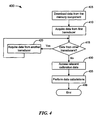
- FIG. 4 depicts a flow diagram illustrating an example process 400 of retrieving and using stored data for multiple transducers from a single memory component.
- the system downloads the data from the memory component directly coupled to one of the transducers. Then at block 410 the system acquires data from a first transducer.
- the system determines whether data from another transducer needs to be acquired. If data from another transducer is needed (block 415 - Yes), the process continues to block 420 to acquire data from the additional transducer. The process then returns to decision block 415. If data is not needed from any other transducer (block 415 - No), the process continues to block 430 where the system accesses the relevant calibration data from the downloaded data.
- the data from all of the transducers in the system can automatically be acquired sequentially, rather than from each transducer independently, depending upon if the data from a particular transducer is needed, as described in blocks 410, 415, 420 above.
- the processor can determine the relevant data and at block 430, the system can access the relevant calibration data.
- the system performs calculations on the measured data using the calibration data, such as adjusting the offset of the measurement data and applying the sensitivity data.
- the process ends at block 499.
- the words “comprise,” “comprising,” and the like are to be construed in an inclusive sense (i.e., to say, in the sense of “including, but not limited to”), as opposed to an exclusive or exhaustive sense.
- the terms “connected,” “coupled,” or any variant thereof means any connection or coupling, either direct or indirect, between two or more elements. Such a coupling or connection between the elements can be physical, logical, or a combination thereof.
- the words “herein,” “above,” “below,” and words of similar import when used in this application, refer to this application as a whole and not to any particular portions of this application.
Landscapes
- Physics & Mathematics (AREA)
- General Physics & Mathematics (AREA)
- Engineering & Computer Science (AREA)
- Technology Law (AREA)
- Testing Or Calibration Of Command Recording Devices (AREA)
- Indication And Recording Devices For Special Purposes And Tariff Metering Devices (AREA)
- Arrangements For Transmission Of Measured Signals (AREA)
Applications Claiming Priority (1)
| Application Number | Priority Date | Filing Date | Title |
|---|---|---|---|
| US12/850,501 US9243938B2 (en) | 2010-08-04 | 2010-08-04 | Single TEDS electronic data sheet for multiple accelerometers |
Publications (2)
| Publication Number | Publication Date |
|---|---|
| EP2418463A2 true EP2418463A2 (de) | 2012-02-15 |
| EP2418463A3 EP2418463A3 (de) | 2017-07-05 |
Family
ID=45338000
Family Applications (1)
| Application Number | Title | Priority Date | Filing Date |
|---|---|---|---|
| EP10172308.8A Withdrawn EP2418463A3 (de) | 2010-08-04 | 2010-08-09 | Elektronisches Datenblatt eines Einzelwandlers |
Country Status (4)
| Country | Link |
|---|---|
| US (1) | US9243938B2 (de) |
| EP (1) | EP2418463A3 (de) |
| JP (1) | JP5908227B2 (de) |
| CN (1) | CN102374875B (de) |
Families Citing this family (9)
| Publication number | Priority date | Publication date | Assignee | Title |
|---|---|---|---|---|
| US9255859B2 (en) | 2010-11-15 | 2016-02-09 | Advanced Mechanical Technology, Inc. | Force platform system |
| DE102012014584A1 (de) * | 2012-07-23 | 2014-01-23 | Hottinger Baldwin Messtechnik Gmbh | Messgrößenaufnehmer mit internem Datenspeicher |
| US9410988B2 (en) | 2013-01-31 | 2016-08-09 | Meggitt (Orange County), Inc. | Cable with LED connection indicator and methods of using same |
| EP2950058B1 (de) * | 2014-05-28 | 2018-03-28 | Axis AB | Kalibrierungsdaten in einem Sensorsystem |
| WO2016210360A1 (en) * | 2015-06-24 | 2016-12-29 | Meggitt (Orange County), Inc. | Sensor and cable with local wireless read and write capability and methods of using same |
| DE102015013401B3 (de) * | 2015-10-19 | 2017-03-02 | Schenck Process Europe Gmbh | Vorrichtung und Verfahren zur Kalibrierung und/oder Justage von Messeinrichtungen für dynamische Kräfte |
| CN105912341A (zh) * | 2016-04-27 | 2016-08-31 | 乐视控股(北京)有限公司 | 一种传感器的校准参数的配置方法及电子设备 |
| JP7336152B2 (ja) | 2018-05-22 | 2023-08-31 | ユープリー | 環境を監視するシステム |
| US11879957B2 (en) * | 2021-10-07 | 2024-01-23 | Schneider Electric USA, Inc. | Systems and methods for calibrating a TEDS compliant connected energy meter |
Family Cites Families (14)
| Publication number | Priority date | Publication date | Assignee | Title |
|---|---|---|---|---|
| JPH08320748A (ja) * | 1995-05-24 | 1996-12-03 | Japan Aviation Electron Ind Ltd | センサ処理装置及びシステム |
| AU4200300A (en) * | 1999-04-06 | 2000-10-23 | Thornton Associates, Inc. | Multiplexing sensor signals |
| JP2002008081A (ja) | 2000-06-26 | 2002-01-11 | Toyota Motor Corp | 車輌用データ記録装置 |
| US7834754B2 (en) * | 2002-07-19 | 2010-11-16 | Ut-Battelle, Llc | Method and system for monitoring environmental conditions |
| DE10356629C5 (de) | 2003-12-01 | 2010-06-02 | Krohne Meßtechnik GmbH & Co KG | Verfahren zum Betreiben eines elektronischen Meßgeräts |
| US7206710B2 (en) | 2005-01-14 | 2007-04-17 | Verigy Pte. Ltd. | Incremental generation of calibration factors for automated test equipment |
| JP2006208031A (ja) * | 2005-01-25 | 2006-08-10 | Hitachi Ulsi Systems Co Ltd | 半導体センサ装置とその製造方法と補正方法 |
| JP4635948B2 (ja) * | 2006-04-18 | 2011-02-23 | 株式会社デンソー | センサ装置およびそれを用いた制御システム |
| US7933731B2 (en) * | 2008-02-29 | 2011-04-26 | Omega Engineering, Inc. | Smart sensor |
| JP2009222400A (ja) * | 2008-03-13 | 2009-10-01 | Yamatake Corp | センサシステム |
| DE102008032046A1 (de) * | 2008-07-08 | 2010-01-14 | Magna Powertrain Ag & Co Kg | Kalibrierungsverfahren für ein Positionsbestimmungssystem eines Hinterachslenkungsaktuators |
| EP2184591B1 (de) | 2008-11-05 | 2016-05-25 | VEGA Grieshaber KG | Sensor mit Speicher aufweisenden Baugruppen |
| US8266169B2 (en) * | 2008-12-18 | 2012-09-11 | Palo Alto Reseach Center Incorporated | Complex queries for corpus indexing and search |
| JP5339057B2 (ja) * | 2009-01-28 | 2013-11-13 | 横河電機株式会社 | 測定装置 |
-
2010
- 2010-08-04 US US12/850,501 patent/US9243938B2/en active Active
- 2010-08-09 EP EP10172308.8A patent/EP2418463A3/de not_active Withdrawn
-
2011
- 2011-01-18 CN CN201110020438.2A patent/CN102374875B/zh active Active
- 2011-07-21 JP JP2011159842A patent/JP5908227B2/ja active Active
Non-Patent Citations (1)
| Title |
|---|
| None |
Also Published As
| Publication number | Publication date |
|---|---|
| EP2418463A3 (de) | 2017-07-05 |
| CN102374875A (zh) | 2012-03-14 |
| JP2012037513A (ja) | 2012-02-23 |
| US20120035869A1 (en) | 2012-02-09 |
| JP5908227B2 (ja) | 2016-04-26 |
| US9243938B2 (en) | 2016-01-26 |
| CN102374875B (zh) | 2016-06-29 |
Similar Documents
| Publication | Publication Date | Title |
|---|---|---|
| US9243938B2 (en) | Single TEDS electronic data sheet for multiple accelerometers | |
| CA1273813A (en) | Apparatus and method for calibrating a sensor | |
| JP4975822B2 (ja) | 改良されたフィールド装置校正 | |
| US20080257039A1 (en) | Device and Method for the Gravimetric Determination of Liquid Volumes and Analyzer System Comprising Such a Device | |
| JP7765460B2 (ja) | 被試験デバイスのユニバーサルキャリブレーションのための方法及びシステム | |
| US7979227B2 (en) | Calibration in a laboratory reference method | |
| MXPA06006361A (es) | Identificacion de tipos de flujometros. | |
| CN116134295A (zh) | 借助机器学习方法校准和操作传感器组件的方法和设备 | |
| CN104914275A (zh) | 一种新型mems电容式加速度计温度补偿电路 | |
| CN103808349A (zh) | 矢量传感器的误差校正方法和装置 | |
| GB2464734A (en) | Providing sensor device specific calibration coefficients for sensor based measurements | |
| CN110530544A (zh) | 一种温度校正方法及系统 | |
| US6560555B1 (en) | Method for facilitating the field replacement of sensors | |
| CN105180995A (zh) | 一种测量校准系统及方法 | |
| CN120313763B (zh) | 一种测温设备温度自动校准方法 | |
| KR101146288B1 (ko) | 자동 교정 장치, 자동 교정 방법 및 자동 교정 방법을 기록한 프로그램 기록 매체 | |
| CN116576904B (zh) | 传感器测试方法及装置、电子设备及计算机可读存储介质 | |
| US5798692A (en) | Digital compensation circuit for calibration of sensors | |
| SE523545C2 (sv) | Metod, en portabel anordning och ett mätinstrument för standardisering av ett satellitmätinstrument till ett motsvarande huvudmätinstrument | |
| MXPA05001802A (es) | Dispositivo de medicion inalambrico. | |
| NL2032690B1 (en) | Micropipette or add-on device for a micropipette comprising at least two magnetometers | |
| JP7741901B2 (ja) | 空間的に広く分散されたセンサ測定箇所を有する測定アセンブリを取り付け、動作させる方法 | |
| CN112585433A (zh) | 用于校准设备的传感器的方法和传感器系统 | |
| US12436005B2 (en) | System for operating a physical measuring chain | |
| JPH0882637A (ja) | 半導体センサ装置および半導体センサ装置の感度調整方法 |
Legal Events
| Date | Code | Title | Description |
|---|---|---|---|
| AK | Designated contracting states |
Kind code of ref document: A2 Designated state(s): AL AT BE BG CH CY CZ DE DK EE ES FI FR GB GR HR HU IE IS IT LI LT LU LV MC MK MT NL NO PL PT RO SE SI SK SM TR |
|
| AX | Request for extension of the european patent |
Extension state: BA ME RS |
|
| PUAI | Public reference made under article 153(3) epc to a published international application that has entered the european phase |
Free format text: ORIGINAL CODE: 0009012 |
|
| PUAL | Search report despatched |
Free format text: ORIGINAL CODE: 0009013 |
|
| AK | Designated contracting states |
Kind code of ref document: A3 Designated state(s): AL AT BE BG CH CY CZ DE DK EE ES FI FR GB GR HR HU IE IS IT LI LT LU LV MC MK MT NL NO PL PT RO SE SI SK SM TR |
|
| AX | Request for extension of the european patent |
Extension state: BA ME RS |
|
| RIC1 | Information provided on ipc code assigned before grant |
Ipc: G01D 18/00 20060101AFI20170526BHEP Ipc: G01D 3/02 20060101ALI20170526BHEP Ipc: G01D 21/02 20060101ALI20170526BHEP |
|
| 17P | Request for examination filed |
Effective date: 20180103 |
|
| RBV | Designated contracting states (corrected) |
Designated state(s): AL AT BE BG CH CY CZ DE DK EE ES FI FR GB GR HR HU IE IS IT LI LT LU LV MC MK MT NL NO PL PT RO SE SI SK SM TR |
|
| STAA | Information on the status of an ep patent application or granted ep patent |
Free format text: STATUS: THE APPLICATION HAS BEEN WITHDRAWN |
|
| 17Q | First examination report despatched |
Effective date: 20200428 |
|
| 18W | Application withdrawn |
Effective date: 20200515 |