EP2417880A2 - Cooking appliance control method - Google Patents
Cooking appliance control method Download PDFInfo
- Publication number
- EP2417880A2 EP2417880A2 EP10761845A EP10761845A EP2417880A2 EP 2417880 A2 EP2417880 A2 EP 2417880A2 EP 10761845 A EP10761845 A EP 10761845A EP 10761845 A EP10761845 A EP 10761845A EP 2417880 A2 EP2417880 A2 EP 2417880A2
- Authority
- EP
- European Patent Office
- Prior art keywords
- cooking chamber
- convection
- heating source
- radiant heating
- heater
- Prior art date
- Legal status (The legal status is an assumption and is not a legal conclusion. Google has not performed a legal analysis and makes no representation as to the accuracy of the status listed.)
- Granted
Links
Images
Classifications
-
- A—HUMAN NECESSITIES
- A47—FURNITURE; DOMESTIC ARTICLES OR APPLIANCES; COFFEE MILLS; SPICE MILLS; SUCTION CLEANERS IN GENERAL
- A47J—KITCHEN EQUIPMENT; COFFEE MILLS; SPICE MILLS; APPARATUS FOR MAKING BEVERAGES
- A47J36/00—Parts, details or accessories of cooking-vessels
-
- F—MECHANICAL ENGINEERING; LIGHTING; HEATING; WEAPONS; BLASTING
- F24—HEATING; RANGES; VENTILATING
- F24C—DOMESTIC STOVES OR RANGES ; DETAILS OF DOMESTIC STOVES OR RANGES, OF GENERAL APPLICATION
- F24C15/00—Details
- F24C15/32—Arrangements of ducts for hot gases, e.g. in or around baking ovens
- F24C15/322—Arrangements of ducts for hot gases, e.g. in or around baking ovens with forced circulation
- F24C15/327—Arrangements of ducts for hot gases, e.g. in or around baking ovens with forced circulation with air moisturising
-
- A—HUMAN NECESSITIES
- A21—BAKING; EDIBLE DOUGHS
- A21B—BAKERS' OVENS; MACHINES OR EQUIPMENT FOR BAKING
- A21B3/00—Parts or accessories of ovens
- A21B3/04—Air-treatment devices for ovens, e.g. regulating humidity
-
- A—HUMAN NECESSITIES
- A47—FURNITURE; DOMESTIC ARTICLES OR APPLIANCES; COFFEE MILLS; SPICE MILLS; SUCTION CLEANERS IN GENERAL
- A47J—KITCHEN EQUIPMENT; COFFEE MILLS; SPICE MILLS; APPARATUS FOR MAKING BEVERAGES
- A47J27/00—Cooking-vessels
-
- A—HUMAN NECESSITIES
- A47—FURNITURE; DOMESTIC ARTICLES OR APPLIANCES; COFFEE MILLS; SPICE MILLS; SUCTION CLEANERS IN GENERAL
- A47J—KITCHEN EQUIPMENT; COFFEE MILLS; SPICE MILLS; APPARATUS FOR MAKING BEVERAGES
- A47J27/00—Cooking-vessels
- A47J27/04—Cooking-vessels for cooking food in steam; Devices for extracting fruit juice by means of steam ; Vacuum cooking vessels
-
- A—HUMAN NECESSITIES
- A47—FURNITURE; DOMESTIC ARTICLES OR APPLIANCES; COFFEE MILLS; SPICE MILLS; SUCTION CLEANERS IN GENERAL
- A47J—KITCHEN EQUIPMENT; COFFEE MILLS; SPICE MILLS; APPARATUS FOR MAKING BEVERAGES
- A47J36/00—Parts, details or accessories of cooking-vessels
- A47J36/32—Time-controlled igniting mechanisms or alarm devices
Definitions
- the present disclosure relates a cooker, and more particularly, to a method for controlling a cooker for deodorization.
- a cooker refers to an electronic appliance for heating food using electricity or gas.
- the cooker is provided with a cooking chamber where food is cooked, and various kinds of heating sources providing energy for cooking food in the cooking chamber are used.
- steam supplied into the cooking chamber may be discharged into the cooker.
- Embodiments provide a method of controlling a method of controlling a cooker configured to perform the deodorization of a cooking chamber more effectively.
- a method for controlling a cooker includes: oscillating microwave supplied to a cooking chamber, by a high-frequency heating source; and generating steam supplied to the cooking chamber, by a steam generator, wherein in a case a signal for initiating the operation of the steam generator is input before the operation of the high-frequency heating source is started, the operation of the steam generator is initiated at a preset time separately of a time when the operation of the high-frequency heating source is started, and in a case a signal for initiating the operation of the steam generator is input after the operation of the high-frequency heating source is started, the operation of the steam generator is initiated at a time when the signal is input.
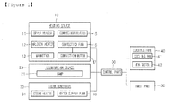
- Fig. 1 is a schematic view of a cooker controlled by a method for controlling a cooker according to an embodiment.
- a heating source 10 for cooking food in a cooking chamber includes an upper heater 11, a halogen heater 12 and a magnetron 13.
- the upper heater 11 is installed in the upper part of a cooking chamber to provide radiating heat for the cooking chamber.
- a Sheath heater may be used.
- the halogen heater 12 provides radiating heat including light and heat to the cooking chamber.
- the halogen heater 12 provides radiating heat to the cooking chamber through a porous part (not shown) installed in the upper part of the cooking chamber and formed at the ceiling of the cooking chamber.
- the magnetron 13 oscillates microwave illuminated inward the cooking chamber.
- the heating source 10 further includes a convention heater 15, a convention fan 16 and a convection motor 17.
- the convection heater 15, the convection fan 16 and the convection motor 17 supply convective heat to the cooking chamber. More particularly, since air heated by the convection heater 15 circulates around the cooking chamber by the operation of the convection fan 16, convective heat is supplied to the cooking chamber.
- the convection motor 17 provides a drive force for the operation of the convection fan 16.
- an illumination source 20 illuminates inside the cooking chamber.
- a lamp 21 may be used.
- a steam generator 30 may be provided to supply steam into the cooking chamber.
- the steam generator 30 includes a steam heater 31 and a water supply pump 33.
- the steam heater 31 heats steam water for generating steam supplied to the cooking chamber.
- the water supply pump 33 supplies steam water heated by the steam heater 31.
- a cooling part 40 For the cooling of the heating source 10 and the ventilation of the inside of the cooking chamber, a cooling part 40 may be provided.
- the cooling part 40 includes a cooling fan 41 and a fan motor 43. That is, by means of air flowing by the cooling fan 41 and the fan motor 43, the encapsulation parts of the halogen heater 12, a magnetron 13, a steam heater 31 and a water supply pump 33 may be cooled. Also, in a case the fan motor 43 is driven, the cooling fan 41 operates so that the exterior air may be supplied inside the cooking chamber, and air let inside the cooking chamber may be drained to the exterior of the cooking chamber in a state of containing oil and moisture, etc., existing in the cooking chamber.
- a manipulation signal for the operation of the heating source 10 and the steam generator 30 is input to an input part 50.
- the input part 50 receives a manipulation signal for the deodorization of the cooking chamber.
- the input part 50 may be configured of more than two buttons respectively receiving a manipulation signal for food cooking in the cooking chamber or a manipulation signal for the deodorization in the cooking chamber.
- control part 60 controls to perform operations for cooking food in the cooking chamber.
- control part 60 controls the operation of the upper heater 11, the halogen heater 12, the convection heater 15, the convection motor 17, the lamp 21, the steam heater 31, the water supply pump 33 and the fan motor 43 according to an manipulation signal inputted into the input part 50 for the deodorization of the cooking chamber.
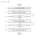
- Fig. 2 is a control flowchart illustrating a method for controlling a cooker according to a an embodiment.
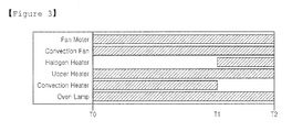
- Fig. 3 is a graph illustrating operating times of components according to the an embodiment.
- the input part 50 initially receives a manipulation signal for the deodorization of the cooking chamber after food cooking inside the cooking chamber is completed (S11).
- the control part 60 controls to initiate the operation of an upper heater 11, a convection heater 15, an convection motor 17, the lamp 21 and a fan motor 43 (S13).
- the upper heater 11 repeats an ON/OFF action at a preset time interval.
- the convection heater 15 repeats an ON/OFF action to maintain a temperature inside the cooking chamber around a preset temperature. Also, the lamp 21 and the fan motor 43 continue ON action.
- the control part 60 determines if they have arrived at a preset first time (T1) according to the manipulation signal (S15). In operation S15, determined that the first time (T1) has arrived, the control part 60 controls to end the operation of the convection heater 15, and to initiate the operation of the halogen heater 12 (S17).
- the control part 60 determines if a preset second time (T2) according to the manipulation signal has arrived (S19). In operation S19, determined that a preset second time (T2) has arrived, the control part 60 controls to finish the operation of the upper heater 11, the halogen heater 12, the convection motor 17, the lamp 21 and the fan motor 43 (S21).
- the upper heater 11 and the halogen heater 12 are operated for radiant heating inside the cooking chamber and the convection heater 15 and the convection motor 17 are operated for convective heating inside the cooking chamber, for the purpose of the deodorization of the cooking chamber. Also, in a state the inside of the cooking chamber is heated as described above, the fan motor 43 is operated to ventilate the cooking chamber, so that the deodorization of the cooking chamber is performed.
- the deodorization of a cooking chamber is effectively performed by the operation of a radiant heating source, a convective heating source and a convection apparatus.
- the embodiment may expect an effect to use a cooker more cleanly.
Abstract
Description
- The present disclosure relates a cooker, and more particularly, to a method for controlling a cooker for deodorization.
- A cooker refers to an electronic appliance for heating food using electricity or gas. The cooker is provided with a cooking chamber where food is cooked, and various kinds of heating sources providing energy for cooking food in the cooking chamber are used.
- However, steam supplied into the cooking chamber may be discharged into the cooker.
- Embodiments provide a method of controlling a method of controlling a cooker configured to perform the deodorization of a cooking chamber more effectively.
- In one embodiment, a method for controlling a cooker includes: oscillating microwave supplied to a cooking chamber, by a high-frequency heating source; and generating steam supplied to the cooking chamber, by a steam generator, wherein in a case a signal for initiating the operation of the steam generator is input before the operation of the high-frequency heating source is started, the operation of the steam generator is initiated at a preset time separately of a time when the operation of the high-frequency heating source is started, and in a case a signal for initiating the operation of the steam generator is input after the operation of the high-frequency heating source is started, the operation of the steam generator is initiated at a time when the signal is input.
- The details of one or more embodiments are set forth in the accompanying drawings and the description below. Other features will be apparent from the description and drawings, and from the claims.
- According to the embodiment, there is a benefit capable of performing the deodorization of a cooking chamber in a more effective way.
-
-
Fig. 1 is a schematic view of a cooker controlled by a method for controlling a cooker according to an embodiment. -
Fig. 2 is a control flowchart illustrating a method for controlling a cooker according to an embodiment. -
Fig. 3 is a graph illustrating operating times of components according to the embodiment. - Hereinafter, a cooker controlling method according to embodiments will be explained in detail with reference to the accompanying drawings.
-
Fig. 1 is a schematic view of a cooker controlled by a method for controlling a cooker according to an embodiment. - Referring to
Fig. 1 , in the present embodiment, aheating source 10 for cooking food in a cooking chamber includes anupper heater 11, ahalogen heater 12 and amagnetron 13. Theupper heater 11 is installed in the upper part of a cooking chamber to provide radiating heat for the cooking chamber. As theupper heater 11, a Sheath heater may be used. And, thehalogen heater 12 provides radiating heat including light and heat to the cooking chamber. Thehalogen heater 12 provides radiating heat to the cooking chamber through a porous part (not shown) installed in the upper part of the cooking chamber and formed at the ceiling of the cooking chamber. Themagnetron 13 oscillates microwave illuminated inward the cooking chamber. - Also, the
heating source 10 further includes aconvention heater 15, aconvention fan 16 and aconvection motor 17. Theconvection heater 15, theconvection fan 16 and theconvection motor 17 supply convective heat to the cooking chamber. More particularly, since air heated by theconvection heater 15 circulates around the cooking chamber by the operation of theconvection fan 16, convective heat is supplied to the cooking chamber. Theconvection motor 17 provides a drive force for the operation of theconvection fan 16. - On the one hand, an
illumination source 20 illuminates inside the cooking chamber. As theillumination source 20, alamp 21 may be used. - And, a
steam generator 30 may be provided to supply steam into the cooking chamber. Thesteam generator 30 includes asteam heater 31 and awater supply pump 33. Thesteam heater 31 heats steam water for generating steam supplied to the cooking chamber. Thewater supply pump 33 supplies steam water heated by thesteam heater 31. - For the cooling of the
heating source 10 and the ventilation of the inside of the cooking chamber, acooling part 40 may be provided. Thecooling part 40 includes acooling fan 41 and afan motor 43. That is, by means of air flowing by thecooling fan 41 and thefan motor 43, the encapsulation parts of thehalogen heater 12, amagnetron 13, asteam heater 31 and awater supply pump 33 may be cooled. Also, in a case thefan motor 43 is driven, thecooling fan 41 operates so that the exterior air may be supplied inside the cooking chamber, and air let inside the cooking chamber may be drained to the exterior of the cooking chamber in a state of containing oil and moisture, etc., existing in the cooking chamber. A manipulation signal for the operation of theheating source 10 and thesteam generator 30 is input to aninput part 50. Particularly, in this embodiment, theinput part 50 receives a manipulation signal for the deodorization of the cooking chamber. For example, theinput part 50 may be configured of more than two buttons respectively receiving a manipulation signal for food cooking in the cooking chamber or a manipulation signal for the deodorization in the cooking chamber. - In the meantime, the
control part 60 controls to perform operations for cooking food in the cooking chamber. In particular, thecontrol part 60 controls the operation of theupper heater 11, thehalogen heater 12, theconvection heater 15, theconvection motor 17, thelamp 21, thesteam heater 31, thewater supply pump 33 and thefan motor 43 according to an manipulation signal inputted into theinput part 50 for the deodorization of the cooking chamber. - Hereinafter, a cooker controlling method according to an embodiment will be described in detail with reference to the accompanying drawings.
-
Fig. 2 is a control flowchart illustrating a method for controlling a cooker according to a an embodiment.Fig. 3 is a graph illustrating operating times of components according to the an embodiment. - *23Referring to
Figs. 2 and3 , theinput part 50 initially receives a manipulation signal for the deodorization of the cooking chamber after food cooking inside the cooking chamber is completed (S11). - In operation S11, in a case the
input part 50 receives the manipulation signal, thecontrol part 60 controls to initiate the operation of anupper heater 11, aconvection heater 15, anconvection motor 17, thelamp 21 and a fan motor 43 (S13). At -this time, theupper heater 11 repeats an ON/OFF action at a preset time interval. And, theconvection heater 15 repeats an ON/OFF action to maintain a temperature inside the cooking chamber around a preset temperature. Also, thelamp 21 and thefan motor 43 continue ON action. - And, after the operation of the
upper heater 11, theconvection heater 15, theconvection motor 17, thelamp 21 and thefan motor 43 was initiated, thecontrol part 60 determines if they have arrived at a preset first time (T1) according to the manipulation signal (S15). In operation S15, determined that the first time (T1) has arrived, thecontrol part 60 controls to end the operation of theconvection heater 15, and to initiate the operation of the halogen heater 12 (S17). - Next, after the operation of the
convection heater 15 is ended, and the operation of thehalogen heater 12 is initiated, thecontrol part 60 determines if a preset second time (T2) according to the manipulation signal has arrived (S19). In operation S19, determined that a preset second time (T2) has arrived, thecontrol part 60 controls to finish the operation of theupper heater 11, thehalogen heater 12, theconvection motor 17, thelamp 21 and the fan motor 43 (S21). - Therefore, in the present embodiment, the
upper heater 11 and thehalogen heater 12 are operated for radiant heating inside the cooking chamber and theconvection heater 15 and theconvection motor 17 are operated for convective heating inside the cooking chamber, for the purpose of the deodorization of the cooking chamber. Also, in a state the inside of the cooking chamber is heated as described above, thefan motor 43 is operated to ventilate the cooking chamber, so that the deodorization of the cooking chamber is performed. - In the control of the present embodiment, a specific operation of the
upper heater 11, thehalogen heater 12, theconvection motor 17, the steam heater 25, the water supply pump 27, thelamp 21 and thefan motor 43 will be understood more definitely with reference to Fig. 4. - As described above, in a cooker controlling method according to the embodiment, the deodorization of a cooking chamber is effectively performed by the operation of a radiant heating source, a convective heating source and a convection apparatus. Thus, the embodiment may expect an effect to use a cooker more cleanly.
- Although embodiments have been described with reference to a number of illustrative embodiments thereof, it should be understood that numerous other modifications and embodiments can be devised by those skilled in the art that will fall within the spirit and scope of the principles of this disclosure. More particularly, various variations and modifications are possible in the component parts and/or arrangements of the subject combination arrangement within the scope of the disclosure, the drawings and the appended claims. In addition to variations and modifications in the component parts atid/or arrangements, alternative uses will also be apparent to those skilled in the art.
- While it has not been described in detail in the above-mentioned embodiments, in the course of cooking food in the cooking chamber, the operation of the upper heater, the halogen heater, the magnetron, the convection heater, the convection motor, the steam heater and the water supply pump would be ended when the cooking chamber is opened, that is, when a door entering into the cooking chamber is open. Considering it is the fact applying to a general cooker, for example an electronic range, the related detailed description will be omitted.
- Although embodiments have been described with reference to a number of illustrative embodiments thereof, it should be understood that numerous other modifications and embodiments can be devised by those skilled in the art that will fall within the spirit and scope of the principles of this disclosure. More particularly, various variations and modifications are possible in the component parts and/or arrangements of the subject combination arrangement within the scope of the disclosure, the drawings and the appended claims. In addition to variations and modifications in the component parts and/or arrangements, alternative uses will also be apparent to those skilled in the art.
Claims (15)
- A method for controlling a cooker, comprising:supplying steam for the cooking chamber, by a steam generator; andoperating during a respective preset operation time by a convection motor and a convection heater so as to circulate air inside the cooking chamber or furnish convective heat into the cooking chamber, in a case a steam supply into the cooking chamber by the steam generator is completed,wherein the operation time of the convection motor and the operation time of the convection heater are partially overlapped.
- The method according to claim 1, wherein the convection heater operation is initiated after the convection motor operation is started.
- The method according to claim 1, wherein the convection motor operation and the convection heater operation have the same start point and a different end point.
- The method according to claim 1,
wherein the convection motor continues an ON action during its operation time, and
wherein the convection heater repeats an ON/OFF action during its operation time so as to maintain the temperature of the cooking chamber at a preset temperature. - The method according to claim 1, further comprising the operation of operating a radiant heating source radiantly heating the inside of the cooking chamber during a preset operation time.
- The method according to claim 5, wherein the start point and end point of the radiant heating source operation is set the same as the end point of the convection heater operation and the end point of the convection motor operation, or the same as the start point and end point of the convection motor operation.
- The method according to claim 1, further comprising the operation of radiantly heating the inside of the cooking chamber by a first radiant heating source and a second radiant heating source,
wherein the operation of the first radiant heating source is initiated in a case the operation of the convection heater is ended, and completed in a case the operation of the convection motor is ended, and
wherein the operation of the second radiant heating source is initiated in a case the operation of the convection fan is started, and completed in a case the operation of the convection motor is ended - The method according to claim 7, wherein the first radiant heating source and the second radiant heating source repeat an ON/OFF action at a preset time interval.
- A method for controlling a cooker, comprising:furnishing steam into a cooking chamber by a steam generator;operating a convection motor and a convection heater, respectively, to circulate air inside the cooking chamber or to supply convective heat into the cooking chamber in a case a steam supply into the cooking chamber by the steam generator is completed, andsupplying radiant heat into the cooking chamber by a first radiant heating source and a second radiant heating source in a case a steam supply into the cooking chamber by the steam generator is completed,wherein one of the convection heater, the first and the second radiant heating source operates reciprocally among them.
- The method according to claim 9, wherein the convection motor continues an ON action during a preset operation time.
- The method according to claim 9, wherein the convection heater repeats an ON/OFF action during a preset operation time so as to maintain the temperature of the cooking chamber at a preset temperature.
- The method according to claim 9, wherein the operation of the convection heater is initiated in a case a preset time has elapsed after the operation of the convection motor is started.
- The method according to claim 9,
wherein the first radiant heating source is a halogen heater installed at the upper part of the cooking chamber, and
wherein the second radiant heating source is a Sheath heater installed at the upper part of the cooking chamber. - The method according to claim 9, wherein the first and the second radiant heating source repeat an ON/OFF action at a preset time interval during a respective preset operation time.
- The method according to claim 9,
wherein the operation of the first radiant heating source is initiated in a case the operation of the convection heater is ended, and completed in a case the operation of the convection motor is ended, and
wherein the operation of the second radiant heating source is initiated and completed at the same time the operation of the convection motor is started and ended.
Applications Claiming Priority (2)
| Application Number | Priority Date | Filing Date | Title |
|---|---|---|---|
| KR1020090029657A KR101086161B1 (en) | 2009-04-06 | 2009-04-06 | Method for controlling cooker |
| PCT/KR2010/002090 WO2010117184A2 (en) | 2009-04-06 | 2010-04-06 | Cooking appliance control method |
Publications (3)
| Publication Number | Publication Date |
|---|---|
| EP2417880A2 true EP2417880A2 (en) | 2012-02-15 |
| EP2417880A4 EP2417880A4 (en) | 2014-08-13 |
| EP2417880B1 EP2417880B1 (en) | 2017-09-20 |
Family
ID=42936703
Family Applications (1)
| Application Number | Title | Priority Date | Filing Date |
|---|---|---|---|
| EP10761845.6A Active EP2417880B1 (en) | 2009-04-06 | 2010-04-06 | Cooking appliance control method |
Country Status (3)
| Country | Link |
|---|---|
| EP (1) | EP2417880B1 (en) |
| KR (1) | KR101086161B1 (en) |
| WO (1) | WO2010117184A2 (en) |
Cited By (5)
| Publication number | Priority date | Publication date | Assignee | Title |
|---|---|---|---|---|
| US9936706B2 (en) | 2013-06-27 | 2018-04-10 | Middleby Marshall Holding Llc | Forced moisture evacuation for rapid baking |
| US10694753B2 (en) | 2013-05-23 | 2020-06-30 | Duke Manufacturing Co. | Food preparation apparatus and methods |
| US10874250B2 (en) | 2015-01-23 | 2020-12-29 | Balmuda Inc. | Heating cooker |
| US10918112B2 (en) | 2013-05-23 | 2021-02-16 | Duke Manufacturing Co. | Dough preparation apparatus and methods |
| US11229322B2 (en) | 2020-04-06 | 2022-01-25 | Sharkninja Operating Llc | Dynamic flip toaster |
Citations (4)
| Publication number | Priority date | Publication date | Assignee | Title |
|---|---|---|---|---|
| JP2005282893A (en) * | 2004-03-29 | 2005-10-13 | Mitsubishi Electric Corp | Heating cooker |
| EP1654931A2 (en) * | 2004-11-05 | 2006-05-10 | LG Electronics, Inc. | Steam generator for steam oven |
| KR100710218B1 (en) * | 2005-12-22 | 2007-04-20 | 엘지전자 주식회사 | Steam oven |
| EP1962021A2 (en) * | 2007-02-26 | 2008-08-27 | Samsung Electronics Co., Ltd. | Cooking apparatus and method of controlling the same |
Family Cites Families (4)
| Publication number | Priority date | Publication date | Assignee | Title |
|---|---|---|---|---|
| KR100624080B1 (en) * | 2003-12-09 | 2006-09-19 | 삼성전자주식회사 | Heating cooker |
| KR101041071B1 (en) * | 2003-12-30 | 2011-06-13 | 삼성전자주식회사 | Heating cooker |
| KR100691224B1 (en) | 2005-05-31 | 2007-03-09 | 삼성전자주식회사 | A steam cooking apparatus and method to clean the cooking cavity thereof |
| KR100643694B1 (en) | 2005-06-10 | 2006-11-10 | 삼성전자주식회사 | Apparatus to control cleaning of cooker with steam generation device and method thereof |
-
2009
- 2009-04-06 KR KR1020090029657A patent/KR101086161B1/en active IP Right Grant
-
2010
- 2010-04-06 WO PCT/KR2010/002090 patent/WO2010117184A2/en active Application Filing
- 2010-04-06 EP EP10761845.6A patent/EP2417880B1/en active Active
Patent Citations (4)
| Publication number | Priority date | Publication date | Assignee | Title |
|---|---|---|---|---|
| JP2005282893A (en) * | 2004-03-29 | 2005-10-13 | Mitsubishi Electric Corp | Heating cooker |
| EP1654931A2 (en) * | 2004-11-05 | 2006-05-10 | LG Electronics, Inc. | Steam generator for steam oven |
| KR100710218B1 (en) * | 2005-12-22 | 2007-04-20 | 엘지전자 주식회사 | Steam oven |
| EP1962021A2 (en) * | 2007-02-26 | 2008-08-27 | Samsung Electronics Co., Ltd. | Cooking apparatus and method of controlling the same |
Non-Patent Citations (1)
| Title |
|---|
| See also references of WO2010117184A2 * |
Cited By (9)
| Publication number | Priority date | Publication date | Assignee | Title |
|---|---|---|---|---|
| US10694753B2 (en) | 2013-05-23 | 2020-06-30 | Duke Manufacturing Co. | Food preparation apparatus and methods |
| US10918112B2 (en) | 2013-05-23 | 2021-02-16 | Duke Manufacturing Co. | Dough preparation apparatus and methods |
| US11602149B2 (en) | 2013-05-23 | 2023-03-14 | Duke Manufacturing Co. | Food preparation apparatus and methods |
| US11779023B2 (en) | 2013-05-23 | 2023-10-10 | Duke Manufacturing Co. | Dough preparation apparatus and methods |
| US9936706B2 (en) | 2013-06-27 | 2018-04-10 | Middleby Marshall Holding Llc | Forced moisture evacuation for rapid baking |
| US10874250B2 (en) | 2015-01-23 | 2020-12-29 | Balmuda Inc. | Heating cooker |
| US11877692B2 (en) | 2015-01-23 | 2024-01-23 | Balmuda Inc. | Heating cooker |
| US11229322B2 (en) | 2020-04-06 | 2022-01-25 | Sharkninja Operating Llc | Dynamic flip toaster |
| US11445859B2 (en) | 2020-04-06 | 2022-09-20 | Sharkninja Operating Llc | Dynamic flip toaster |
Also Published As
| Publication number | Publication date |
|---|---|
| WO2010117184A2 (en) | 2010-10-14 |
| WO2010117184A3 (en) | 2011-03-10 |
| KR101086161B1 (en) | 2011-11-25 |
| EP2417880A4 (en) | 2014-08-13 |
| KR20100111204A (en) | 2010-10-14 |
| EP2417880B1 (en) | 2017-09-20 |
Similar Documents
| Publication | Publication Date | Title |
|---|---|---|
| EP2417880B1 (en) | Cooking appliance control method | |
| EP2417882B2 (en) | Cooking appliance control method | |
| KR102384745B1 (en) | A cooking apparatus and method for controlling the same | |
| EP2417883B1 (en) | Method for controlling a cooking apparatus | |
| WO2014020872A1 (en) | Heat cooking device | |
| KR101152540B1 (en) | Method for cleaning cooking chamber in cooker | |
| KR101596501B1 (en) | Cooker and method for controlling the same | |
| EP2417884B1 (en) | Cooking appliance control method | |
| KR100996363B1 (en) | Cooker and method for controlling the same | |
| KR100432751B1 (en) | A heating temperature control method of microwave oven | |
| KR101152560B1 (en) | Method for cleaning steam generator for cooker | |
| KR100288915B1 (en) | Cooling control method of microwave oven | |
| KR100565660B1 (en) | Apparatus and Method for Controlling Combination Mode of The Microwave Oven | |
| KR100938862B1 (en) | Cooker and method for controlling the same | |
| KR20090124343A (en) | Cooker | |
| KR20090106072A (en) | Cooker and method for controlling the same | |
| KR20090071249A (en) | Cooling fan rpm control method for microwave oven | |
| KR20100081248A (en) | Heat insulation method of microwave oven | |
| KR20090106071A (en) | Cooker and method for controlling the same | |
| KR20060073223A (en) | A heating control method of microwave oven |
Legal Events
| Date | Code | Title | Description |
|---|---|---|---|
| PUAI | Public reference made under article 153(3) epc to a published international application that has entered the european phase |
Free format text: ORIGINAL CODE: 0009012 |
|
| 17P | Request for examination filed |
Effective date: 20111103 |
|
| AK | Designated contracting states |
Kind code of ref document: A2 Designated state(s): AT BE BG CH CY CZ DE DK EE ES FI FR GB GR HR HU IE IS IT LI LT LU LV MC MK MT NL NO PL PT RO SE SI SK SM TR |
|
| DAX | Request for extension of the european patent (deleted) | ||
| A4 | Supplementary search report drawn up and despatched |
Effective date: 20140714 |
|
| RIC1 | Information provided on ipc code assigned before grant |
Ipc: F24C 15/32 20060101ALI20140708BHEP Ipc: A21B 3/04 20060101ALI20140708BHEP Ipc: A47J 27/62 20060101ALI20140708BHEP Ipc: A47J 27/04 20060101AFI20140708BHEP |
|
| REG | Reference to a national code |
Ref country code: DE Ref legal event code: R079 Ref document number: 602010045384 Country of ref document: DE Free format text: PREVIOUS MAIN CLASS: A47J0027000000 Ipc: A47J0027040000 |
|
| GRAP | Despatch of communication of intention to grant a patent |
Free format text: ORIGINAL CODE: EPIDOSNIGR1 |
|
| RIC1 | Information provided on ipc code assigned before grant |
Ipc: A47J 27/04 20060101AFI20170310BHEP Ipc: A47J 27/62 20060101ALI20170310BHEP Ipc: F24C 15/32 20060101ALI20170310BHEP Ipc: A21B 3/04 20060101ALI20170310BHEP |
|
| INTG | Intention to grant announced |
Effective date: 20170410 |
|
| GRAS | Grant fee paid |
Free format text: ORIGINAL CODE: EPIDOSNIGR3 |
|
| GRAA | (expected) grant |
Free format text: ORIGINAL CODE: 0009210 |
|
| AK | Designated contracting states |
Kind code of ref document: B1 Designated state(s): AT BE BG CH CY CZ DE DK EE ES FI FR GB GR HR HU IE IS IT LI LT LU LV MC MK MT NL NO PL PT RO SE SI SK SM TR |
|
| REG | Reference to a national code |
Ref country code: GB Ref legal event code: FG4D |
|
| REG | Reference to a national code |
Ref country code: CH Ref legal event code: EP |
|
| REG | Reference to a national code |
Ref country code: AT Ref legal event code: REF Ref document number: 929483 Country of ref document: AT Kind code of ref document: T Effective date: 20171015 |
|
| REG | Reference to a national code |
Ref country code: IE Ref legal event code: FG4D |
|
| REG | Reference to a national code |
Ref country code: DE Ref legal event code: R096 Ref document number: 602010045384 Country of ref document: DE |
|
| REG | Reference to a national code |
Ref country code: NL Ref legal event code: MP Effective date: 20170920 |
|
| PG25 | Lapsed in a contracting state [announced via postgrant information from national office to epo] |
Ref country code: HR Free format text: LAPSE BECAUSE OF FAILURE TO SUBMIT A TRANSLATION OF THE DESCRIPTION OR TO PAY THE FEE WITHIN THE PRESCRIBED TIME-LIMIT Effective date: 20170920 Ref country code: NO Free format text: LAPSE BECAUSE OF FAILURE TO SUBMIT A TRANSLATION OF THE DESCRIPTION OR TO PAY THE FEE WITHIN THE PRESCRIBED TIME-LIMIT Effective date: 20171220 Ref country code: LT Free format text: LAPSE BECAUSE OF FAILURE TO SUBMIT A TRANSLATION OF THE DESCRIPTION OR TO PAY THE FEE WITHIN THE PRESCRIBED TIME-LIMIT Effective date: 20170920 Ref country code: FI Free format text: LAPSE BECAUSE OF FAILURE TO SUBMIT A TRANSLATION OF THE DESCRIPTION OR TO PAY THE FEE WITHIN THE PRESCRIBED TIME-LIMIT Effective date: 20170920 Ref country code: SE Free format text: LAPSE BECAUSE OF FAILURE TO SUBMIT A TRANSLATION OF THE DESCRIPTION OR TO PAY THE FEE WITHIN THE PRESCRIBED TIME-LIMIT Effective date: 20170920 |
|
| REG | Reference to a national code |
Ref country code: LT Ref legal event code: MG4D |
|
| REG | Reference to a national code |
Ref country code: AT Ref legal event code: MK05 Ref document number: 929483 Country of ref document: AT Kind code of ref document: T Effective date: 20170920 |
|
| PG25 | Lapsed in a contracting state [announced via postgrant information from national office to epo] |
Ref country code: LV Free format text: LAPSE BECAUSE OF FAILURE TO SUBMIT A TRANSLATION OF THE DESCRIPTION OR TO PAY THE FEE WITHIN THE PRESCRIBED TIME-LIMIT Effective date: 20170920 Ref country code: GR Free format text: LAPSE BECAUSE OF FAILURE TO SUBMIT A TRANSLATION OF THE DESCRIPTION OR TO PAY THE FEE WITHIN THE PRESCRIBED TIME-LIMIT Effective date: 20171221 Ref country code: BG Free format text: LAPSE BECAUSE OF FAILURE TO SUBMIT A TRANSLATION OF THE DESCRIPTION OR TO PAY THE FEE WITHIN THE PRESCRIBED TIME-LIMIT Effective date: 20171220 |
|
| PG25 | Lapsed in a contracting state [announced via postgrant information from national office to epo] |
Ref country code: NL Free format text: LAPSE BECAUSE OF FAILURE TO SUBMIT A TRANSLATION OF THE DESCRIPTION OR TO PAY THE FEE WITHIN THE PRESCRIBED TIME-LIMIT Effective date: 20170920 |
|
| PG25 | Lapsed in a contracting state [announced via postgrant information from national office to epo] |
Ref country code: CZ Free format text: LAPSE BECAUSE OF FAILURE TO SUBMIT A TRANSLATION OF THE DESCRIPTION OR TO PAY THE FEE WITHIN THE PRESCRIBED TIME-LIMIT Effective date: 20170920 Ref country code: PL Free format text: LAPSE BECAUSE OF FAILURE TO SUBMIT A TRANSLATION OF THE DESCRIPTION OR TO PAY THE FEE WITHIN THE PRESCRIBED TIME-LIMIT Effective date: 20170920 Ref country code: ES Free format text: LAPSE BECAUSE OF FAILURE TO SUBMIT A TRANSLATION OF THE DESCRIPTION OR TO PAY THE FEE WITHIN THE PRESCRIBED TIME-LIMIT Effective date: 20170920 Ref country code: RO Free format text: LAPSE BECAUSE OF FAILURE TO SUBMIT A TRANSLATION OF THE DESCRIPTION OR TO PAY THE FEE WITHIN THE PRESCRIBED TIME-LIMIT Effective date: 20170920 |
|
| PG25 | Lapsed in a contracting state [announced via postgrant information from national office to epo] |
Ref country code: IS Free format text: LAPSE BECAUSE OF FAILURE TO SUBMIT A TRANSLATION OF THE DESCRIPTION OR TO PAY THE FEE WITHIN THE PRESCRIBED TIME-LIMIT Effective date: 20180120 Ref country code: EE Free format text: LAPSE BECAUSE OF FAILURE TO SUBMIT A TRANSLATION OF THE DESCRIPTION OR TO PAY THE FEE WITHIN THE PRESCRIBED TIME-LIMIT Effective date: 20170920 Ref country code: IT Free format text: LAPSE BECAUSE OF FAILURE TO SUBMIT A TRANSLATION OF THE DESCRIPTION OR TO PAY THE FEE WITHIN THE PRESCRIBED TIME-LIMIT Effective date: 20170920 Ref country code: AT Free format text: LAPSE BECAUSE OF FAILURE TO SUBMIT A TRANSLATION OF THE DESCRIPTION OR TO PAY THE FEE WITHIN THE PRESCRIBED TIME-LIMIT Effective date: 20170920 Ref country code: SK Free format text: LAPSE BECAUSE OF FAILURE TO SUBMIT A TRANSLATION OF THE DESCRIPTION OR TO PAY THE FEE WITHIN THE PRESCRIBED TIME-LIMIT Effective date: 20170920 Ref country code: SM Free format text: LAPSE BECAUSE OF FAILURE TO SUBMIT A TRANSLATION OF THE DESCRIPTION OR TO PAY THE FEE WITHIN THE PRESCRIBED TIME-LIMIT Effective date: 20170920 |
|
| REG | Reference to a national code |
Ref country code: DE Ref legal event code: R097 Ref document number: 602010045384 Country of ref document: DE |
|
| PLBE | No opposition filed within time limit |
Free format text: ORIGINAL CODE: 0009261 |
|
| STAA | Information on the status of an ep patent application or granted ep patent |
Free format text: STATUS: NO OPPOSITION FILED WITHIN TIME LIMIT |
|
| PG25 | Lapsed in a contracting state [announced via postgrant information from national office to epo] |
Ref country code: DK Free format text: LAPSE BECAUSE OF FAILURE TO SUBMIT A TRANSLATION OF THE DESCRIPTION OR TO PAY THE FEE WITHIN THE PRESCRIBED TIME-LIMIT Effective date: 20170920 |
|
| 26N | No opposition filed |
Effective date: 20180621 |
|
| PG25 | Lapsed in a contracting state [announced via postgrant information from national office to epo] |
Ref country code: SI Free format text: LAPSE BECAUSE OF FAILURE TO SUBMIT A TRANSLATION OF THE DESCRIPTION OR TO PAY THE FEE WITHIN THE PRESCRIBED TIME-LIMIT Effective date: 20170920 Ref country code: MC Free format text: LAPSE BECAUSE OF FAILURE TO SUBMIT A TRANSLATION OF THE DESCRIPTION OR TO PAY THE FEE WITHIN THE PRESCRIBED TIME-LIMIT Effective date: 20170920 |
|
| REG | Reference to a national code |
Ref country code: CH Ref legal event code: PL |
|
| REG | Reference to a national code |
Ref country code: BE Ref legal event code: MM Effective date: 20180430 |
|
| GBPC | Gb: european patent ceased through non-payment of renewal fee |
Effective date: 20180406 |
|
| REG | Reference to a national code |
Ref country code: IE Ref legal event code: MM4A |
|
| PG25 | Lapsed in a contracting state [announced via postgrant information from national office to epo] |
Ref country code: LU Free format text: LAPSE BECAUSE OF NON-PAYMENT OF DUE FEES Effective date: 20180406 |
|
| PG25 | Lapsed in a contracting state [announced via postgrant information from national office to epo] |
Ref country code: CH Free format text: LAPSE BECAUSE OF NON-PAYMENT OF DUE FEES Effective date: 20180430 Ref country code: BE Free format text: LAPSE BECAUSE OF NON-PAYMENT OF DUE FEES Effective date: 20180430 Ref country code: LI Free format text: LAPSE BECAUSE OF NON-PAYMENT OF DUE FEES Effective date: 20180430 Ref country code: GB Free format text: LAPSE BECAUSE OF NON-PAYMENT OF DUE FEES Effective date: 20180406 |
|
| PG25 | Lapsed in a contracting state [announced via postgrant information from national office to epo] |
Ref country code: IE Free format text: LAPSE BECAUSE OF NON-PAYMENT OF DUE FEES Effective date: 20180406 Ref country code: FR Free format text: LAPSE BECAUSE OF NON-PAYMENT OF DUE FEES Effective date: 20180430 |
|
| PG25 | Lapsed in a contracting state [announced via postgrant information from national office to epo] |
Ref country code: MT Free format text: LAPSE BECAUSE OF NON-PAYMENT OF DUE FEES Effective date: 20180406 |
|
| PG25 | Lapsed in a contracting state [announced via postgrant information from national office to epo] |
Ref country code: TR Free format text: LAPSE BECAUSE OF FAILURE TO SUBMIT A TRANSLATION OF THE DESCRIPTION OR TO PAY THE FEE WITHIN THE PRESCRIBED TIME-LIMIT Effective date: 20170920 |
|
| PG25 | Lapsed in a contracting state [announced via postgrant information from national office to epo] |
Ref country code: PT Free format text: LAPSE BECAUSE OF FAILURE TO SUBMIT A TRANSLATION OF THE DESCRIPTION OR TO PAY THE FEE WITHIN THE PRESCRIBED TIME-LIMIT Effective date: 20170920 Ref country code: HU Free format text: LAPSE BECAUSE OF FAILURE TO SUBMIT A TRANSLATION OF THE DESCRIPTION OR TO PAY THE FEE WITHIN THE PRESCRIBED TIME-LIMIT; INVALID AB INITIO Effective date: 20100406 |
|
| PG25 | Lapsed in a contracting state [announced via postgrant information from national office to epo] |
Ref country code: CY Free format text: LAPSE BECAUSE OF FAILURE TO SUBMIT A TRANSLATION OF THE DESCRIPTION OR TO PAY THE FEE WITHIN THE PRESCRIBED TIME-LIMIT Effective date: 20170920 Ref country code: MK Free format text: LAPSE BECAUSE OF NON-PAYMENT OF DUE FEES Effective date: 20170920 |
|
| PGFP | Annual fee paid to national office [announced via postgrant information from national office to epo] |
Ref country code: DE Payment date: 20230306 Year of fee payment: 14 |