EP2417618B1 - Detector, device, and method for the simultaneous, energy-dispersive recording of backscattered electrons and x-ray quanta - Google Patents
Detector, device, and method for the simultaneous, energy-dispersive recording of backscattered electrons and x-ray quanta Download PDFInfo
- Publication number
- EP2417618B1 EP2417618B1 EP10722019A EP10722019A EP2417618B1 EP 2417618 B1 EP2417618 B1 EP 2417618B1 EP 10722019 A EP10722019 A EP 10722019A EP 10722019 A EP10722019 A EP 10722019A EP 2417618 B1 EP2417618 B1 EP 2417618B1
- Authority
- EP
- European Patent Office
- Prior art keywords
- detector
- contribution
- ray
- electrons
- radiation
- Prior art date
- Legal status (The legal status is an assumption and is not a legal conclusion. Google has not performed a legal analysis and makes no representation as to the accuracy of the status listed.)
- Active
Links
Images

Classifications
-
- H—ELECTRICITY
- H01—ELECTRIC ELEMENTS
- H01J—ELECTRIC DISCHARGE TUBES OR DISCHARGE LAMPS
- H01J37/00—Discharge tubes with provision for introducing objects or material to be exposed to the discharge, e.g. for the purpose of examination or processing thereof
- H01J37/02—Details
- H01J37/244—Detectors; Associated components or circuits therefor
-
- H—ELECTRICITY
- H01—ELECTRIC ELEMENTS
- H01J—ELECTRIC DISCHARGE TUBES OR DISCHARGE LAMPS
- H01J37/00—Discharge tubes with provision for introducing objects or material to be exposed to the discharge, e.g. for the purpose of examination or processing thereof
- H01J37/252—Tubes for spot-analysing by electron or ion beams; Microanalysers
- H01J37/256—Tubes for spot-analysing by electron or ion beams; Microanalysers using scanning beams
-
- H—ELECTRICITY
- H01—ELECTRIC ELEMENTS
- H01J—ELECTRIC DISCHARGE TUBES OR DISCHARGE LAMPS
- H01J37/00—Discharge tubes with provision for introducing objects or material to be exposed to the discharge, e.g. for the purpose of examination or processing thereof
- H01J37/26—Electron or ion microscopes; Electron or ion diffraction tubes
- H01J37/28—Electron or ion microscopes; Electron or ion diffraction tubes with scanning beams
-
- H—ELECTRICITY
- H01—ELECTRIC ELEMENTS
- H01J—ELECTRIC DISCHARGE TUBES OR DISCHARGE LAMPS
- H01J2237/00—Discharge tubes exposing object to beam, e.g. for analysis treatment, etching, imaging
- H01J2237/244—Detection characterized by the detecting means
- H01J2237/2441—Semiconductor detectors, e.g. diodes
- H01J2237/24415—X-ray
- H01J2237/2442—Energy-dispersive (Si-Li type) spectrometer
-
- H—ELECTRICITY
- H01—ELECTRIC ELEMENTS
- H01J—ELECTRIC DISCHARGE TUBES OR DISCHARGE LAMPS
- H01J2237/00—Discharge tubes exposing object to beam, e.g. for analysis treatment, etching, imaging
- H01J2237/244—Detection characterized by the detecting means
- H01J2237/24475—Scattered electron detectors
-
- H—ELECTRICITY
- H01—ELECTRIC ELEMENTS
- H01J—ELECTRIC DISCHARGE TUBES OR DISCHARGE LAMPS
- H01J2237/00—Discharge tubes exposing object to beam, e.g. for analysis treatment, etching, imaging
- H01J2237/244—Detection characterized by the detecting means
- H01J2237/24485—Energy spectrometers
-
- H—ELECTRICITY
- H01—ELECTRIC ELEMENTS
- H01J—ELECTRIC DISCHARGE TUBES OR DISCHARGE LAMPS
- H01J2237/00—Discharge tubes exposing object to beam, e.g. for analysis treatment, etching, imaging
- H01J2237/244—Detection characterized by the detecting means
- H01J2237/24495—Signal processing, e.g. mixing of two or more signals
Definitions
- the invention relates to a detector for the simultaneous, energy-dispersive recording of backscattered electrons and X-ray quanta, a device for the simultaneous, energy-dispersive recording of backscattered electrons and X-ray quanta and a method for the simultaneous energy-dispersive measurement of backscattered electrons and X-ray quanta.
- BSE detectors Due to the fact that the BSE detectors usually have several segments (usually 2 or 4), additional information can be obtained by adding or subtracting the channels. An addition results in a composition contrast (Z-contrast), a subtraction results in a topology contrast, thus reproducing the surface structure.
- Z-contrast composition contrast
- topology contrast topology contrast
- an X-ray detector can be used to analyze the elemental composition at the examined site of the sample.
- the photons that fall into the detector crystal are converted into a voltage pulse at whose voltage value one can determine the energy of the electrons, it is therefore an energy-dispersive Detector.
- This detector is not imaging, but provides spectra that can chemically characterize the sample.
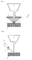
- Fig. 2 shows an X-ray detector 6 of the prior art.
- an electron trap is set in front of the detector 6 by default, which prevents the entry of electrons into the detector 6.
- Lithium-dripped silicon detectors, Si (Li), or silicon drift detectors, SDD are commonly used.
- BSE detectors that operate at lower excitation energies and in which the energy threshold from which the electrons are measured can be precisely adjusted by a filter potential at the grating.
- GB-A-2295454 discloses a detector corresponding to the preamble of claim 1.
- a detector for the simultaneous energy-dispersive recording of backscattered electrons and X-radiation after excitation of a sample with primary electrons, comprising: an energy dispersive X-ray detector element for detecting X-radiation and backscattered electrons, and a means for reducing the contribution of the backscattered electrons to the contribution of the X-radiation in front of the X-ray detector element is, and the means is designed such that the contribution of the backscattered electrons to the contribution of the X-radiation is reduced such that the characteristic peaks of the X-ray radiation with respect to the measurement signal of the backscattered electron contribution can be detected, and at the same time after deduction of the theoretical Röntgenbremsstrahluntergrundes from the measured spectrum, a backscatter electron contribution is detectable.
- the means may be arranged such that at least one of the features formed from the group of the following features applies: the number of detected backscattered electrons has the same order of magnitude as the number of detected x-ray photons; the sum of the areas under the X-ray peaks has the same order of magnitude as the area of the remaining background contribution less the theoretical background of the brake-jet; the number of pulses at the maximum of the X-ray peak is at least 1.5 times the number of pulses of the background contribution in the immediate vicinity of the peak, or at least twice or at least five times.
- the X-ray detector element can be a complete X-ray detector or preferably only the actual detection element or the detection crystal of the X-ray detector.
- the determination as to whether backscattered electrons are present in the spectrum can be made via a known sample such that, if the course of the brake-beam background corresponds to the theory, then no backscattered electrons are present. If the course is different from the theory, then backscattered electrons are present.
- the detector is equipped with a means for reducing the backscattered electron content relative to the X-ray photon fraction, which does not appreciably reduce the intensity of the X-ray radiation, but correspondingly reduces the number of significantly more intense BSEs emitted by the sample, so that the X-ray quanta and BSE can be measured simultaneously. Namely, since the number of backscattered electrons BSE emitted from the specimen is several orders of magnitude higher than the number of X-ray photons, no simultaneous measurement is possible without a specific reduction means, the signal ratio of photons to BSE would be too unfavorable.
- a corresponding means preferably a foil or a window, is necessary, which lets through the largest possible number of photons undisturbed and at the same time reduces the number of BSE so that the number of both types of particles is of the same order of magnitude.
- the resulting X-ray quanta and backscatter electrons can be detected simultaneously and evaluated separately.
- the two different spectral components do not influence each other significantly, so there is an additive superimposition of these components. Therefore, it is possible to separate the spectral contributions in a known general form of the two spectra by means of an algorithm.
- the means for reducing also suppresses secondary electrons SE, i. Low energy electrons.
- the energy resolution for photons is in the range of 130eV for Mn-K ⁇ .
- the analysis of the BSE spectrum is also possible.
- the energy resolution is ⁇ 1 keV.
- the means for the reduction can be designed in such a way that the contribution of the backscattered electrons to the contribution of the x-ray radiation is reduced in such a way that the characteristic peaks of the x-ray radiation are detectable with respect to the measurement signal of the backscattered electron contribution, and at the same time a retransfer electron contribution with respect to the x-ray peaks is detectable after deduction of the theoretical x-ray brake-beam background is.
- the means for reduction can be designed such that the number of detected backscattered electrons differs from the number of detected X-ray quanta by a factor of less than 100, preferably by a factor less than 50, more preferably by a factor of less than 10.
- the means may be designed such that the sums of the areas under the X-ray peaks differ from the area of the remaining contribution by a factor of less than 100, preferably by a factor of less than 50, more preferably by a factor of less than 10.
- the detector may contain at its center a hole for the passage of primary electrons. Therefore, it can advantageously be arranged directly in the electron beam path between the primary electron source and the sample.
- the detector may be divided into several sectors, preferably four sectors. These can be used for analysis with composition and topology contrast as in the conventional BSE detector. At low excitation energy, a spectrum generated solely by X-ray radiation can be measured without BSE contributions. By means of different windows for different sectors, spectra with and without BSE contribution can thus be measured simultaneously for an adapted excitation energy, so that the evaluation of the different signals can be simplified thereby.
- the X-ray detector element may be a semiconductor detector and / or a silicon drift detector.
- the detector can be designed such that it detects a solid angle of 0.5-2 sr.
- the detector according to the invention is possible with the detector according to the invention and the analytic information is obtained as in a conventional X-ray detector with the additional advantage of a large solid angle.
- the reducing agent may consist of polymers and / or of one of the elements selected from the group consisting of polyethylene terephthalate and poly (p-xylylene).
- the means for reduction is preferably a foil which is arranged on the input side of the x-ray detector element.
- the film thickness may be less than 3 microns, preferably 1.5-2.5 microns.
- the film thickness may be 3-5 ⁇ m, preferably 3.5-4.5 ⁇ m.
- the film thickness can be 5-9 ⁇ m, preferably 7.5-8.5 ⁇ m.
- an apparatus for simultaneous measurement of X-rays and backscattered electrons comprising a primary electron beam source; a sample holder disposed in the emission region of the electron beam source; a detector according to the invention, arranged in the electron beam path between the primary electron beam source and the sample holder, and a means for evaluating the measured data.
- the distance between sample holder and detector can be in the range of 2 to 40 mm.
- a method for the simultaneous measurement and evaluation of backscattered electrons and X-radiation comprising the steps: irradiation of a sample with primary electrons; Backscattering of electrons from the sample onto the detector and simultaneous irradiation of the detector with X-radiation from the sample, wherein the contribution of the backscattered electrons in front of the X-ray detector element is reduced such that at least one of the features formed from the group of the following features applies: the number of detected ones Backscattered electrons have the same order of magnitude as the number of detected X-ray photons; the sum of the areas under the X-ray peaks is the same order of magnitude as the area of the background contribution minus the theoretical background of the brake-jet; the pulse energy of an X-ray peak in electron volts is at least 1.5 times the pulse energy of the background contribution in the immediate vicinity of the peak, or at least twice or at least five times.
- the contribution of the backscattered electrons to the contribution of the X-ray radiation can be reduced in such a way that the characteristic peaks of the X-radiation are detectable with respect to the measurement signal of the backscattered electron contribution, and at the same time after the theoretical X-ray brake-beam background has been subtracted, a backscattered electron contribution can be detected with respect to the X-ray peaks.
- the theoretically calculated X-ray brake-beam background can be subtracted from the energy-resolved measured data.
- the subtraction can be done in the area of the asymptotic drop of the theoretically calculated X-ray brake-beam background and from the data obtained
- a mapping can be made by assigning a greyscale value or color value to the area size or count.
- an analysis of the total number of electrons in the spectrum would be similar to an analysis in the conventional BSE detector.
- the dissolution of the BSE energy enables the selection of the electrons at different energies and thus from different penetration depths, i. the analysis is deep-sensitive. Thereby one can e.g. Investigate layer systems.
- the interaction volume increases with greater depth and the interaction volume from which the photons originate is large, the evaluation of backscattered electrons low energy, the lateral resolution is higher than in the evaluation of all backscattered electrons or the evaluation of photons.
- composition and topology contrast Different sectors also make it possible to measure composition and topology contrast. Additional information can be obtained by combining the segment signals with the distinction of electron intensity for different energies.
- FIGS. 1 and 2 show a backscattered electron detector 2 and a prior art X-ray detector 6, as already described in the introduction.
- a peak in a spectrum is "detectable” if it can be separated from the ground.
- a linear background can be constructed below the peak. This can be determined by specifying on the high- and low-energy side of the peak in each case a point that is at least twice the half-width of the peak from the central channel and visually located in the ground and connects these two points by a straight line.
- the peak intensity P is the sum of all counts in the peak area above this line.
- the background value U is the number of counts below the line, but only in the one central channel below the peak.
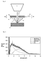
- FIG. 3 shows an inventive device for simultaneous energy-resolved measurement of backscattered electrons and X-rays.
- the implementation consists of the detector 10 as in Fig. 3 1, which comprises a conventional energy-dispersive X-ray detector element 12, in front of which there is arranged a means (11) for reducing the contribution of the backscattered electrons to the contribution of the X-ray radiation, as well as suitable software which detect spectra and if necessary separate the components of the photons and BSE and can evaluate separately.
- the detector 10 as in Fig. 3 1, which comprises a conventional energy-dispersive X-ray detector element 12, in front of which there is arranged a means (11) for reducing the contribution of the backscattered electrons to the contribution of the X-ray radiation, as well as suitable software which detect spectra and if necessary separate the components of the photons and BSE and can evaluate separately.
- the energy dispersive X-ray detector element 12 is an element made of a material, as it is used for the actual detection of X-radiation in an X-ray detector. It is preferably semiconductor detector element 12, more preferably an element 12, as used in a silicon drift detector consisting of silicon or Si (Li).
- a silicon drift detector can not only detect X-rays, but also ionizing particles such as electrons.
- electrons By the incident ionizing radiation electrons are excited in the semiconductor.
- An X-ray quantum that penetrates into the semiconductor material can lift its energy due to the photoelectric effect of an electron of the valence to an unoccupied state of the conduction band of the semiconductor. There will be a hole left in the valence band.
- the released electron excites further electrons, and further electron-hole pairs are formed, which migrate to the electrodes due to an electric field.
- a penetrating electron generates electron-hole pairs along its orbit in the semiconductor, which in turn generate further electron-hole pairs.
- the X-ray detector element 12 is arranged flatter in the detector 10 with respect to a conventional X-ray detector 6 and with a larger area.
- the height of the X-ray detector element 12 is between 1 and 5 mm and its area varies between 10 mm 2 and 120 mm 2 , preferably between 30 mm 2 and 90 mm 2 , more preferably between 50 mm 2 and 70 mm 2 .
- it is a flat detector crystal, in which the electronic and signal processing 9 is arranged laterally.
- the X-ray detector element 12 may consist of several sub-sectors, which in turn may have a rectangular shape or the shape of a circular element.
- the detector 10 with the X-ray detector element 12 is designed such that it can be arranged directly in the electron beam path 4 between the primary electron source 1 and the sample 3 in comparison to a conventional X-ray detector 6.
- the detector 10 has a hole 8, which is preferably arranged centrally in the detector 10, through which the primary electrons 4 can pass through the detector 10 and reach the sample 3. From the sample 3, the electrons 5 are then backscattered and at the same time X-ray radiation 7 is generated.
- One side of the detector 10 is preferably arranged facing the primary electron source 1, the other side facing the sample 3 arranged.
- the side facing the primary electron source 1 and the opposite side is arranged orthogonal to the primary electron beam 4.
- a detector 10 according to the invention is compared to a conventional X-ray detector 6 of Fig. 2 arranged closer to the sample 3.
- the distance sample 3 to the detector 5 is less than 40 mm, preferably less than 10 mm.
- the means 11 for reducing the contribution of the backscattered electrons 5 to the contribution of the X-radiation 7 is arranged on the input side of the energy-dispersive X-ray detector element 12.
- the means 11 preferably covers the input side of the energy-dispersive X-ray detector element 12 completely. In other words, the incident on the detector 10 X-ray radiation 7 and the incident backscattered electrons 5 must first pass the means 11 before they hit the actual detector element 12 for the detection of X-rays 7 and 5 electrons.
- the means 11 reduces the number of backscattered electrons 5 which strike the energy dispersive X-ray detector element 12 more than the number of X-ray quanta 7, so that the proportion of the backscattered electrons 5 is reduced compared to the proportion of the X-ray quanta 7 in the total input radiation incident on the X-ray detector element 12 becomes.
- the detector 10 is equipped with a means 11 which does not appreciably reduce the intensity of the X-ray radiation 7, but correspondingly reduces the number of substantially more intense BSE 5 emitted by the sample, so that X-ray quanta and BSE are simultaneously measurable.
- the agent 11 also suppresses secondary electrons (SE), i. Low energy electrons.
- the means 11 for reducing the contribution of the backscattered electrons 5 to the contribution of the X-radiation 7 is formed as a film.
- film will be used instead of the term “means 11 for reducing the contribution of the backscattered electrons 5 to the contribution of the X-radiation 7" in order to abbreviate the description.
- the film 11 is preferably arranged with a holder (not shown) in front of the input side of the energy-dispersive X-ray detector element 12. More preferably, the film 11 is arranged interchangeably.
- the detector is not used solely for the measurement of X-ray quanta or the measurement of backscattered electrons, but measures both components.
- a further feature of the film 11 is that the contribution of the backscattered electrons 5 to the contribution of the X-radiation 7 is reduced in such a way that the characteristic peaks of the X-radiation 7 can be detected with respect to the measurement signal of the backscattered electron contribution 5, and at the same time after the theoretical X-ray brake-beam background has been subtracted a backscattered electron contribution is detectable with respect to the X-ray peaks.
- the latter backscatter electron contribution is to be recognized in the spectra especially where the theoretical X-ray brake-beam background asymptotically decreases. If, in the region of the asymptotic decrease of the theoretically calculated X-ray brake-beam background, a difference to the theoretically calculated X-ray brake-beam background is detectable in the spectrum, contributions from backscattered electrons are present.
- the film 11 is selected according to the invention as a function of the excitation energy of the primary electrons 4 used. The fulfillment of the above criteria depending on the excitation energy can then be done by appropriate choice of the film material and / or the film thickness.
- the detector can process X-ray quanta with the resolution of a good X-ray detector and a very high counting rate and represent a common spectrum.
- the count rate can be up to 10 6 events per second.
- the detector 10 may consist of several detector sectors that can measure separately from each other.
- the total area of a detector 10 may be circular, wherein the detector segments may be arranged as circular elements around the hole 8 in the center of the detector 10.
- the detector segments can also be rectangular or square.
- the sectors can be used as in the conventional BSE detector 2 for analysis with composition and topology contrast. Additional information can be obtained by combining the segment signals with the distinction of electron intensity for different energies. If the detector 10 has a plurality of segments, usually 2 or 4, additional information can be obtained by addition or subtraction of the channels: Addition results in a composition contrast (Z contrast), subtraction results in a topology contrast, thus reproducing the surface structure.
- Z contrast composition contrast
- polymers for example polyethylene terephthalate PET [C 10 H 8 O 4 ] n (marketed for example under the trade name Mylar®) or poly (p-xylylene) [C 8 H 8 ] n (for example under the trade name Parylene N® distributed).
- Mylar® polyethylene terephthalate PET
- poly (p-xylylene) for example under the trade name Parylene N® distributed.
- films 11 of different thickness 1 ⁇ m, 2 ⁇ m, 3 ⁇ m and 6 ⁇ m, can be used in order to achieve a comparable contribution by X-ray quanta and BSE for these energies.
- the film thicknesses are 2 microns at an excitation energy of less than 10 keV, 4 microns at an excitation energy of less than 15 keV but greater than 10 keV and 8 microns at an excitation energy of less than 25 keV but greater than 15 keV.
- the stated thicknesses may preferably vary by 0.5 ⁇ m upwards and downwards.
- a spectrum generated only by X-radiation 7 can be measured without BSE contributions 5.
- spectra with and without BSE contribution can thus be measured simultaneously for an adapted excitation energy, so that the evaluation of the different signals can be simplified thereby.
- the energy resolution for photons is preferably in the range of 130 eV for Mn-K ⁇ .
- the analysis of the BSE spectrum is also possible.
- the energy resolution is ⁇ 1 keV.
- An analysis of the total number of electrons 5 in the spectrum would be equivalent to an analysis in the conventional BSE detector 2.
- the resolution of the BSE energy allows for the selection of the electrons 5 at different energies and thus at different depths of penetration, i. the analysis is deep-sensitive. As a result, it is advantageously possible to obtain Investigate layer systems.
- the interaction volume increases with greater depth and the interaction volume from which the photons originate is large, the evaluation of backscattered electrons 5 low energy, the lateral resolution is higher than in the evaluation of all backscattered electrons 5 or the evaluation of photons.
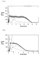
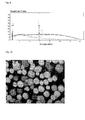
- FIGS. 4 and 5 of carbon (Z 6), measured at an excitation energy of 12 and 15 keV, show the measured spectrum (gray), a fitted background course (BG, black), and the composition of the background from a fraction resulting from photons (braking). BG, dotted, black) and a proportion that results from backscattered electrons (BSE-BG, dashed, black). It can be seen that the BSE and photon contributions for each part of the figures have a characteristic energy curve that is completely different. In addition, the energy dependence of the BSE can be seen.
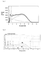
- Fig. 9 shows a spectra for a pure manganese sample, which arise when the film 11 is chosen to be too thick (gray) or too thin (black).
- the thicknesses of the films are 6 ⁇ m and 3 ⁇ m, respectively, with an excitation energy of 18 keV and consist of Mylar®. If the film 11 is too thick, the proportion of the backscattered electrons 5 is completely suppressed and a pure X-ray spectrum (gray) is produced. If a film that is too thin is selected, a spectrum (black) results, in which the proportion of backscattered electrons 5 becomes so high that the characteristic peaks of the X-radiation become so small that they are in the range of the noise of the BSE signal and no more can be evaluated.
- the peaks are no longer detectable.
- the pulse load due to the large number of backscattered electrons 5 becomes too high, so that the detector 10 can no longer process any pulses.
- the spectra differ once by the fact that X-ray peaks are even visible or detectable and on the other hand that in the higher energy range from 3eV, at which the X-ray braking radiation asymptotically decreases, similar Fig. 4 shown, a backscattered electron component is visible.
- the thickness of the film 11 used is 2 ⁇ m.
- the film 11 consists, as already mentioned, of Mylar®.
- the state of the art for the mapping of the spectra is the following procedure: the electron beam is guided in a line over a sample area and a spectrum is recorded at each location. This is evaluated, eg by percentage Cu, Ni, Sn content or by area of the background-corrected peaks. Then every point where the spectrum is was measured, assigned a brightness in a color, so you get a false color image.
- mapping results, as can be obtained from a BSE detector.
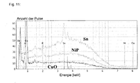
- Fig. 13 shows the pulse height in eV as a function of the energy in keV for the NiP phase of the Fig. 10 (black) and the physics calculated bremsstrahlung background of the x-ray radiation (gray).
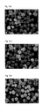
- Fig. 12 to convert the intensities directly into a grayscale value were in Fig. 14 the intensities in the range 4-7 keV after deduction of the theoretical bremsstrahlung background are converted into gray levels, ie the contribution of the spectrum (in the picture dark gray) in the range 4-7 keV minus the background contribution in this energy range (light gray).
- This post is shown in the image as a black area bounded by the gray area. From this area of the spectrum at each point, a mapping can be created in which the area size or the count is assigned a gray value, as shown below.
- mapping results in images that look very similar to a BSE image.
- light Sn phase (high Z, many BSE)
- medium light Ni phase (middle Z)
- dark Cu phase (low Z , little BSE).
- the black background consists of C, ie very low Z with very little BSE.
- the invention relates to an energy-dispersive detector which can simultaneously detect X-rays and backscattered electrons. It has been shown by way of example only and not by way of limitation some applications how to use the detector of the invention and to evaluate the measured data.
Landscapes
- Chemical & Material Sciences (AREA)
- Analytical Chemistry (AREA)
- Analysing Materials By The Use Of Radiation (AREA)
Description
Die Erfindung betrifft einen Detektor zur gleichzeitigen, energiedispersiven Aufnahme von Rückstreuelektronen und Röntgenquanten, eine Vorrichtung zur gleichzeitigen, energiedispersiven Aufnahme von Rückstreuelektronen und Röntgenquanten und ein Verfahren zur gleichzeitigen energiedispersiven Messung von Rückstreuelektronen und Röntgenquanten.The invention relates to a detector for the simultaneous, energy-dispersive recording of backscattered electrons and X-ray quanta, a device for the simultaneous, energy-dispersive recording of backscattered electrons and X-ray quanta and a method for the simultaneous energy-dispersive measurement of backscattered electrons and X-ray quanta.
Es ist bekannt, zur Analyse von Proben in einem Rasterelektronenmikroskop (SEM) verschiedene Signale, die von der Probe abgegeben werden, heranzuziehen und auszuwerten. Zum einen ist es interessant, eine bildgebende Analyse zur Darstellung eines Bildes ähnlich dem Bild in einem Lichtmikroskop, aber mit zusätzlicher Information an jedem Punkt über die mittlere chemische Zusammensetzung, zu erhalten. Dazu eignet sich ein Rückstreuelektronen-Detektor. Zum anderen sind detailliertere Informationen über die in der Probe an dem Punkt enthaltenen Elemente mit deren Zusammensetzung interessant. Dies ist durch eine Elektronenstrahlmikroanalyse und die Detektion der in der Probe erzeugten Röntgenstrahlung möglich. Das Ausgabesignal ist dabei von der Ordnungszahl Z an der untersuchten Stelle der Probe abhängig. Man kann das Signal also zur Darstellung unterschiedlicher Zusammensetzungen der Probe an verschiedenen Stellen nutzen. Dieser Detektor wird somit zur bildgebenden Darstellung verwendet.It is known to use and evaluate various signals emitted by the sample for the analysis of samples in a scanning electron microscope (SEM). On the one hand, it is interesting to obtain an imaging analysis to display an image similar to the image in a light microscope, but with additional information at each point about the average chemical composition. For this purpose, a backscattered electron detector is suitable. On the other hand, more detailed information about the elements contained in the sample at the point and their composition are interesting. This is possible by electron beam microanalysis and the detection of the X-radiation generated in the sample. The output signal is dependent on the ordinal number Z at the examined point of the sample. One can therefore use the signal to represent different compositions of the sample in different places. This detector is thus used for imaging.
Der Rückstreuelektronen-Detektor (BSE-Detektor) 2, wie in
Dadurch, dass die BSE-Detektoren üblicherweise mehrere Segmente aufweisen (meist 2 oder 4), kann man durch Addition oder Subtraktion der Kanäle noch zusätzliche Information erhalten. Eine Addition ergibt einen Kompositionskontrast (Z-Kontrast), eine Subtraktion ergibt einen Topologiekontrast, gibt also die Oberflächenstruktur wieder.Due to the fact that the BSE detectors usually have several segments (usually 2 or 4), additional information can be obtained by adding or subtracting the channels. An addition results in a composition contrast (Z-contrast), a subtraction results in a topology contrast, thus reproducing the surface structure.
Ferner kann ein Röntgen-Detektor zur Analyse der elementaren Zusammensetzung an der untersuchten Stelle der Probe genutzt werden. Bei diesem Detektor werden die Photonen, die in den Detektor-Kristall fallen, in einen Spannungspuls umgewandelt, an dessen Spannungswert man die Energie der Elektronen ermitteln kann, er ist somit ein energiedispersiver Detektor. Dieser Detektor ist nicht bildgebend, sondern liefert Spektren, mit denen man die Probe chemisch charakterisieren kann.Further, an X-ray detector can be used to analyze the elemental composition at the examined site of the sample. In this detector, the photons that fall into the detector crystal are converted into a voltage pulse at whose voltage value one can determine the energy of the electrons, it is therefore an energy-dispersive Detector. This detector is not imaging, but provides spectra that can chemically characterize the sample.
Der Röntgendetektor ist, im Gegensatz zum BSE-Detektor relativ weit von der Probe entfernt und erfasst nur einen kleinen Raumwinkel, etwa Ω=0.01-0.1 sr, verglichen mit dem BSE-Detektor (Ω=0.5-2 sr). Bedingt durch die hinter dem Detektorkristall befindliche Elektronik zur Signalverarbeitung kann er nicht, wie der BSE-Detektor, zwischen Probe und Polschuh geschoben werden.The X-ray detector, unlike the BSE detector, is relatively far away from the sample and only detects a small solid angle, approximately Ω = 0.01-0.1 sr, compared to the BSE detector (Ω = 0.5-2 sr). Due to the signal processing electronics located behind the detector crystal, it can not be pushed between the sample and the pole piece like the BSE detector.
Eine Weiterentwicklung der BSE-Detektoren sind Inlens-Detektoren, die bei niedrigeren Anregungsenergien arbeiten und bei denen die Energieschwelle, ab der die Elektronen gemessen werden, genau eingestellt werden kann, durch ein Filterpotential am Gitter.A further development of the BSE detectors are Inlens detectors that operate at lower excitation energies and in which the energy threshold from which the electrons are measured can be precisely adjusted by a filter potential at the grating.
Ein anderer Ansatz, die Rückstreuelektronen energiedispersiv zu messen, ist der Einsatz eines energiedispersiven Elektronendetektors. Dieser Detektor hat eine Energieauflösung ΔE/E=0.04, einen kleinen Raumwinkel von ca. 0.02 (Öffnungswinkel 22°-18°=4°) und weder kommerziellen Aufbau noch Anwendungen. Es zeigt aber, dass Anwendungen bezüglich Schichtdickenanalysen möglich sind.Another approach to energy-dispersive measurements of the backscattered electrons is the use of an energy-dispersive electron detector. This detector has an energy resolution ΔE / E = 0.04, a small solid angle of about 0.02 (opening angle 22 ° -18 ° = 4 °) and neither commercial construction nor applications. It shows, however, that applications regarding layer thickness analyzes are possible.
Problematisch ist jedoch, Röntgenstrahlen und Rückstreuelektronen mit einem Detektor gleichzeitig zu messen, da das Signalverhältnis Photonen zu BSE ungünstig ist.However, it is problematic to simultaneously measure X-rays and backscatter electrons with a detector, since the signal ratio of photons to BSE is unfavorable.
Es ist daher Aufgabe der Erfindung, einen Detektor bereitzustellen, mit dem gleichzeitig Rückstreuelektronen und Röntgenquanten energieaufgelöst gemessen werden können.It is therefore the object of the invention to provide a detector with which backscattered electrons and X-ray quanta can be measured in an energy-resolved manner.
Entsprechend wird ein Detektor zur gleichzeitigen energiedispersiven Aufnahme von Rückstreuelektronen und Röntgenstrahlung nach Anregung einer Probe mit Primärelektronen vorgeschlagen, umfassend: einen energiedispersives Röntgendetektorelement zur Detektion von Röntgenstrahlung und Rückstreuelektronen, und ein Mittel zur Reduktion des Beitrags der Rückstreuelektronen gegenüber dem Beitrag der Röntgenstrahlung vor dem Röntgendetektorelement angeordnet ist, und das Mittel derart ausgebildet ist, dass der Beitrag der Rückstreuelektronen gegenüber dem Beitrag der Röntgenstrahlung derart verringert wird, dass die charakteristischen Peaks der Röntgenstrahlung gegenüber dem Messsignal des Rückstreuelektronenbeitrags nachweisbar sind, und gleichzeitig nach Abzug des theoretischen Röntgenbremsstrahluntergrundes vom gemessenen Spektrum, ein Rückstreuelektronenbeitrag nachweisbar ist.Accordingly, a detector for the simultaneous energy-dispersive recording of backscattered electrons and X-radiation is proposed after excitation of a sample with primary electrons, comprising: an energy dispersive X-ray detector element for detecting X-radiation and backscattered electrons, and a means for reducing the contribution of the backscattered electrons to the contribution of the X-radiation in front of the X-ray detector element is, and the means is designed such that the contribution of the backscattered electrons to the contribution of the X-radiation is reduced such that the characteristic peaks of the X-ray radiation with respect to the measurement signal of the backscattered electron contribution can be detected, and at the same time after deduction of the theoretical Röntgenbremsstrahluntergrundes from the measured spectrum, a backscatter electron contribution is detectable.
Das Mittel kann derart ausgebildet sein, dass mindestens eines der Merkmale gebildet aus der Gruppe der folgenden Merkmale zutrifft: die Anzahl der detektierten Rückstreuelektronen weist die gleiche Größenordnung auf wie die Anzahl der detektierten Röntgenphotonen; die Summe der Flächen unter den Röntgenpeaks weist die gleiche Größenordnung auf wie die Fläche des übrigen Untergrundbeitrags abzüglich des theoretischen Bremsstrahluntergrundes; die Anzahl der Pulse im Maximum des Röntgenpeaks ist mindestens das 1,5fache der Anzahl der Pulse des Untergrundbeitrags in der direkten Umgebung des Peaks oder mindestens das Doppelte oder mindestens das Fünffache.The means may be arranged such that at least one of the features formed from the group of the following features applies: the number of detected backscattered electrons has the same order of magnitude as the number of detected x-ray photons; the sum of the areas under the X-ray peaks has the same order of magnitude as the area of the remaining background contribution less the theoretical background of the brake-jet; the number of pulses at the maximum of the X-ray peak is at least 1.5 times the number of pulses of the background contribution in the immediate vicinity of the peak, or at least twice or at least five times.
Das Röntgendetektorelement kann ein ganzer Röntgendetektor sein oder bevorzugt lediglich das eigentliche Detektionselement oder der Detektionskristall des Röntgendetektors.The X-ray detector element can be a complete X-ray detector or preferably only the actual detection element or the detection crystal of the X-ray detector.
Die Bestimmung, ob Rückstreuelektronen im Spektrum vorhanden sind kann über eine bekannte Probe derart erfolgen, dass, wenn der Verlauf des Bremsstrahluntergrundes der Theorie entspricht, dann keine Rückstreuelektronen vorhanden sind. Unterscheidet sich der Verlauf von der Theorie, so sind Rückstreuelektronen vorhanden.The determination as to whether backscattered electrons are present in the spectrum can be made via a known sample such that, if the course of the brake-beam background corresponds to the theory, then no backscattered electrons are present. If the course is different from the theory, then backscattered electrons are present.
Der Detektor ist ausgerüstet mit einem Mittel zur Reduktion des Rückstreuelektronenanteils gegenüber dem Röntgenphotonenanteil, welches die Intensität der Röntgenstrahlung nicht nennenswert verringert, aber die Anzahl der von der Probe abgegebenen, wesentlich intensiveren BSE entsprechend verringert, so dass die Röntgenquanten und BSE gleichzeitig messbar sind. Da nämlich die Anzahl der von der Probe abgegebenen Rückstreuelektronen BSE um mehrere Größenordungen höher ist als die Anzahl der Röntgenphotonen, ist ohne ein spezielles Mittel zur Reduktion keine gleichzeitige Messung möglich, das Signalverhältnis Photonen zu BSE wäre zu ungünstig. Deshalb ist ein entsprechendes Mittel, bevorzugt eine Folie oder ein Fenster, notwendig, welches eine möglichst große Zahl von Photonen ungestört durchlässt und gleichzeitig die Anzahl der BSE so verringert, das die Anzahl beider Teilchenarten in der gleichen Größenordnung liegt.The detector is equipped with a means for reducing the backscattered electron content relative to the X-ray photon fraction, which does not appreciably reduce the intensity of the X-ray radiation, but correspondingly reduces the number of significantly more intense BSEs emitted by the sample, so that the X-ray quanta and BSE can be measured simultaneously. Namely, since the number of backscattered electrons BSE emitted from the specimen is several orders of magnitude higher than the number of X-ray photons, no simultaneous measurement is possible without a specific reduction means, the signal ratio of photons to BSE would be too unfavorable. Therefore, a corresponding means, preferably a foil or a window, is necessary, which lets through the largest possible number of photons undisturbed and at the same time reduces the number of BSE so that the number of both types of particles is of the same order of magnitude.
Die entstehenden Röntgenquanten und Rückstreuelektronen können simultan erfasst und getrennt ausgewertet werden. Die beiden unterschiedlichen Spektrenanteile beeinflussen sich nicht signifikant, es ergibt sich also eine additive Überlagerung dieser Anteile. Deshalb ist es möglich, die Spektrenbeiträge bei bekannter genereller Form der beiden Spektren mit Hilfe eines Algorithmus zu trennen.The resulting X-ray quanta and backscatter electrons can be detected simultaneously and evaluated separately. The two different spectral components do not influence each other significantly, so there is an additive superimposition of these components. Therefore, it is possible to separate the spectral contributions in a known general form of the two spectra by means of an algorithm.
Vorteilhafterweise unterdrückt das Mittel zur Reduktion außerdem Sekundärelektronen SE, d.h. Elektronen niedriger Energie.Advantageously, the means for reducing also suppresses secondary electrons SE, i. Low energy electrons.
Die Energieauflösung für Photonen liegt im Bereich von 130eV für Mn-Kα.The energy resolution for photons is in the range of 130eV for Mn-Kα.
Zusätzlich ist aber auch die Analyse des BSE-Spektrums möglich. Hier liegt die Energieauflösung ≤ 1 keV.In addition, however, the analysis of the BSE spectrum is also possible. Here the energy resolution is ≤ 1 keV.
Das Mittel zur Reduktion kann derart ausgebildet sein, dass der Beitrag der Rückstreuelektronen gegenüber dem Beitrag der Röntgenstrahlung derart verringert wird, dass die charakteristischen Peaks der Röntgenstrahlung gegenüber dem Messsignal des Rückstreuelektronenbeitrags nachweisbar sind, und gleichzeitig nach Abzug des theoretischen Röntgenbremsstrahluntergrundes ein Rückstreuelektronenbeitrag gegenüber den Röntgenpeaks nachweisbar ist.The means for the reduction can be designed in such a way that the contribution of the backscattered electrons to the contribution of the x-ray radiation is reduced in such a way that the characteristic peaks of the x-ray radiation are detectable with respect to the measurement signal of the backscattered electron contribution, and at the same time a retransfer electron contribution with respect to the x-ray peaks is detectable after deduction of the theoretical x-ray brake-beam background is.
Das Mittel zur Reduktion kann derart ausgebildet sein, dass sich die Anzahl der detektierten Rückstreuelektronen von der Anzahl der detektierten Röntgenquanten um einen Faktor kleiner 100 unterscheidet, bevorzugt um einen Faktor kleiner 50, noch bevorzugter um einen Faktor kleiner 10.The means for reduction can be designed such that the number of detected backscattered electrons differs from the number of detected X-ray quanta by a factor of less than 100, preferably by a factor less than 50, more preferably by a factor of less than 10.
Das Mittel kann derart ausgebildet sein, dass sich die Summen der Flächen unter den Röntgenpeaks von der Fläche des übrigen Beitrags um einen Faktor kleiner 100 unterscheidet, bevorzugt um einen Faktor kleiner 50, noch bevorzugter um einen Faktor kleiner 10.The means may be designed such that the sums of the areas under the X-ray peaks differ from the area of the remaining contribution by a factor of less than 100, preferably by a factor of less than 50, more preferably by a factor of less than 10.
Der Detektor kann in seinem Zentrum ein Loch zum Durchlass von Primärelektronen enthalten. Daher kann er vorteilhafterweise direkt in den Elektronenstrahlgang zwischen Primärelektronenquelle und Probe angeordnet werden.The detector may contain at its center a hole for the passage of primary electrons. Therefore, it can advantageously be arranged directly in the electron beam path between the primary electron source and the sample.
Der Detektor kann in mehrere Sektoren unterteilt sein, bevorzugt in vier Sektoren. Diese können wie beim konventionellen BSE-Detektor zur Analyse mit Kompositions- und Topologiekontrast verwendet werden. Bei niedriger Anregungsenergie lässt sich ein nur durch Röntgenstrahlung generiertes Spektrum ohne BSE-Beiträge messen. Durch unterschiedliche Fenster für verschiedene Sektoren lassen sich für eine angepasste Anregungsenergie somit Spektren mit und ohne BSE-Beitrag gleichzeitig messen, so dass die Auswertung der unterschiedlichen Signale dadurch vereinfacht werden kann.The detector may be divided into several sectors, preferably four sectors. These can be used for analysis with composition and topology contrast as in the conventional BSE detector. At low excitation energy, a spectrum generated solely by X-ray radiation can be measured without BSE contributions. By means of different windows for different sectors, spectra with and without BSE contribution can thus be measured simultaneously for an adapted excitation energy, so that the evaluation of the different signals can be simplified thereby.
Das Röntgendetektorelement kann ein Halbleiterdetektor und/oder ein Silizium-Drift-Detektor sein.The X-ray detector element may be a semiconductor detector and / or a silicon drift detector.
Der Detektor kann derart ausgebildet sein, dass er einen Raumwinkel von 0,5 - 2 sr erfasst.The detector can be designed such that it detects a solid angle of 0.5-2 sr.
Es ist mit dem erfindungsgemäßen Detektor nicht nur eine qualitative, sondern auch eine quantitative Analyse des Spektrenteils, der durch Photonen erzeugt wird, möglich und man erhält die analytische Aussagekraft wie bei einem konventionellen Röntgendetektor mit dem zusätzlichen Vorteil eines großen Raumwinkels.Not only a qualitative, but also a quantitative analysis of the spectral part, which is generated by photons, is possible with the detector according to the invention and the analytic information is obtained as in a conventional X-ray detector with the additional advantage of a large solid angle.
Das Mittel zur Reduktion kann aus Polymeren bestehen und/oder aus einem der Elemente aus der Gruppe gebildet aus Polyethylenterephthalat und Poly(p-xylylen).The reducing agent may consist of polymers and / or of one of the elements selected from the group consisting of polyethylene terephthalate and poly (p-xylylene).
Das Mittel zur Reduktion ist bevorzugt eine Folie, die auf der Eingangseite des Röntgendetektorelementes angeordnet ist. Für eine Anregungsenergie von Primärelektronen kleiner 10 keV kann die Foliendicke weniger als 3 µm betragen, bevorzugt 1,5-2,5 µm. Für eine Anregungsenergie von Primärelektronen von größer gleich 10 keV und kleiner 15 keV kann die Foliendicke 3-5 µm betragen, bevorzugt 3,5-4,5 µm. Für Anregungsenergien von Primärelektronen von größer gleich 15 keV bis kleiner 25 keV kann die Foliendicke 5-9 µm betragen, bevorzugt 7,5-8,5 µm.The means for reduction is preferably a foil which is arranged on the input side of the x-ray detector element. For an excitation energy of primary electrons smaller than 10 keV, the film thickness may be less than 3 microns, preferably 1.5-2.5 microns. For an excitation energy of primary electrons of greater than or equal to 10 keV and less than 15 keV, the film thickness may be 3-5 μm, preferably 3.5-4.5 μm. For excitation energies of primary electrons of greater than or equal to 15 keV to less than 25 keV, the film thickness can be 5-9 μm, preferably 7.5-8.5 μm.
Entsprechend ist eine Vorrichtung zur Simultanen Messung von Röntgenstrahlen und Rückstreuelektronen angegeben, umfassend eine Primärelektronenstrahlquelle; einen Probenhalter, angeordnet im Emissionsbereich der Elektronenstrahlquelle; einen erfindungsgemäßen Detektor, angeordnet im Elektronenstrahlgang zwischen Primärelektronenstrahlquelle und Probenhalter, und ein Mittel zur Auswertung der Messdaten.Accordingly, there is provided an apparatus for simultaneous measurement of X-rays and backscattered electrons comprising a primary electron beam source; a sample holder disposed in the emission region of the electron beam source; a detector according to the invention, arranged in the electron beam path between the primary electron beam source and the sample holder, and a means for evaluating the measured data.
Der Abstand zwischen Probehalter und Detektor kann im Bereich von 2 bis 40 mm liegen.The distance between sample holder and detector can be in the range of 2 to 40 mm.
Ferner ist ein Verfahren zur gleichzeitigen Messung und Auswertung von Rückstreuelektronen und Röntgenstrahlung mit einer erfindungsgemäßen Vorrichtung vorgeschlagen, umfassend die Schritte: Bestrahlung einer Probe mit Primärelektronen; Rückstreuung von Elektronen von der Probe auf den Detektor und gleichzeitige Bestrahlung des Detektors mit Röntgenstrahlung von der Probe, wobei der Beitrag der Rückstreuelektronen vor dem Röntgendetektorelement derart reduziert wird, dass mindestens eines der Merkmale gebildet aus der Gruppe der folgenden Merkmale zutrifft: die Anzahl der detektierten Rückstreuelektronen weist die gleiche Größenordnung auf wie die Anzahl der detektierten Röntgenphotonen; die Summe der Flächen unter den Röntgenpeaks weist die gleiche Größenordnung auf wie die Fläche des Untergrundbeitrags abzüglich des theoretischen Bremsstrahluntergrundes; die Pulsenergie eines Röntgenpeaks in Elektronenvolt ist mindestens das 1,5fache der Pulsenergie des Untergrundbeitrags in der direkten Umgebung des Peaks oder mindestens das Doppelte oder mindestens das Fünffache.Furthermore, a method for the simultaneous measurement and evaluation of backscattered electrons and X-radiation is proposed with a device according to the invention, comprising the steps: irradiation of a sample with primary electrons; Backscattering of electrons from the sample onto the detector and simultaneous irradiation of the detector with X-radiation from the sample, wherein the contribution of the backscattered electrons in front of the X-ray detector element is reduced such that at least one of the features formed from the group of the following features applies: the number of detected ones Backscattered electrons have the same order of magnitude as the number of detected X-ray photons; the sum of the areas under the X-ray peaks is the same order of magnitude as the area of the background contribution minus the theoretical background of the brake-jet; the pulse energy of an X-ray peak in electron volts is at least 1.5 times the pulse energy of the background contribution in the immediate vicinity of the peak, or at least twice or at least five times.
Der Beitrag der Rückstreuelektronen gegenüber dem Beitrag der Röntgenstrahlung kann derart verringert werden, dass die charakteristischen Peaks der Röntgenstrahlung gegenüber dem Messsignal des Rückstreuelektronenbeitrags nachweisbar sind, und gleichzeitig nach Abzug des theoretischen Röntgenbremsstrahluntergrundes ein Rückstreuelektronenbeitrag gegenüber den Röntgenpeaks nachweisbar ist.The contribution of the backscattered electrons to the contribution of the X-ray radiation can be reduced in such a way that the characteristic peaks of the X-radiation are detectable with respect to the measurement signal of the backscattered electron contribution, and at the same time after the theoretical X-ray brake-beam background has been subtracted, a backscattered electron contribution can be detected with respect to the X-ray peaks.
Zur Auswertung der Messdaten kann der theoretisch berechnete Röntgenbremsstrahluntergrund von den energieaufgelösten Messdaten abgezogen werden.To evaluate the measured data, the theoretically calculated X-ray brake-beam background can be subtracted from the energy-resolved measured data.
Die Subtraktion kann im Bereich des asymptotischen Abfalls der theoretisch berechnete Röntgenbremsstrahluntergrund vorgenommen werden und aus den erhaltenen Daten kann durch Auswertung der Spektren an jedem Punkt der Oberfläche ein Mapping erstellt werden, indem der Flächengröße bzw. der Countzahl ein Grauwert oder Farbwert zugeordnet wird.The subtraction can be done in the area of the asymptotic drop of the theoretically calculated X-ray brake-beam background and from the data obtained By mapping the spectra at each point of the surface, a mapping can be made by assigning a greyscale value or color value to the area size or count.
Grundsätzlich würde eine Analyse der Gesamtzahl der Elektronen im Spektrum einer Analyse im konventionellen BSE-Detektor gleichkommen. Die Auflösung der BSE-Energie ermöglicht die Selektion der Elektronen nach verschiedenen Energien und damit aus verschiedenen Ausdringtiefen, d.h. die Analyse ist tiefensensitiv. Dadurch kann man z.B. Schichtsysteme untersuchen. Da außerdem das Wechselwirkungsvolumen mit größerer Tiefe zunimmt und auch das Wechselwirkungsvolumen, aus dem die Photonen stammen, groß ist, ist durch die Auswertung von Rückstreuelektronen niedriger Energie die laterale Auflösung höher als bei der Auswertung aller Rückstreuelektronen oder der Auswertung von Photonen.Basically, an analysis of the total number of electrons in the spectrum would be similar to an analysis in the conventional BSE detector. The dissolution of the BSE energy enables the selection of the electrons at different energies and thus from different penetration depths, i. the analysis is deep-sensitive. Thereby one can e.g. Investigate layer systems. In addition, since the interaction volume increases with greater depth and the interaction volume from which the photons originate is large, the evaluation of backscattered electrons low energy, the lateral resolution is higher than in the evaluation of all backscattered electrons or the evaluation of photons.
Durch verschiedene Sektoren ist außerdem der Kompositions- und Topologiekontrast messbar. Zusätzliche Informationen kann man durch Kombination der Segmentsignale mit der Unterscheidung der Elektronenintensität für unterschiedliche Energien erhalten.Different sectors also make it possible to measure composition and topology contrast. Additional information can be obtained by combining the segment signals with the distinction of electron intensity for different energies.
Die Erfindung wird im Folgenden anhand einiger Figuren beispielhaft aber nicht beschränkend beschreiben. Es zeigt:
- Fig. 1
- eine Vorrichtung zur Messung von Rückstreuelektronen des Standes der Technik;
- Fig. 2
- eine Vorrichtung zur energieaufgelösten Messung von Röntgenstrahlung des Standes der Technik;
- Fig. 3
- eine erfindungsgemäße Vorrichtung zur gleichzeitigen energieaufgelösten Messung von Rückstreuelektronen und Röntgenstrahlung;
- Fig. 4, 5
- den mit der Vorrichtung der
Fig. 3 gemessenen Zählimpuls in Abhängigkeit von der Energie in einem ersten Beispiel bei 12 keV (Fig. 4 ) und 15 keV (Fig. 5 ) Anregungsenergie; - Fig. 6, 7
- den mit der Vorrichtung der
Fig. 3 gemessenen Zählimpuls in Abhängigkeit von der Energie in einem zweiten Beispiel bei 12 keV (Fig. 6 ) und 15 keV (Fig. 7 ) Anregungsenergie; - Fig. 8
- die Abhängigkeit des mit der Vorrichtung der
Fig. 3 gemessenen Spektrums für Proben mit Z=13, Z=51, und Z=83 als Pulshöhe in Abhängigkeit von der Energie; - Fig. 9
- zwei Spektren eines erfindungsgemäßen Detektors für eine Mn-Probe, einmal mit zu dünner Folie (schwarz) und einmal mit zu dicker Folie (grau);
- Fig. 10
- drei erfindungsgemäße Spektren einer Probe aus CuO, NiP und Sn-haltigen Lotkugeln auf einer C-Schicht;
- Fig. 11
- bildgebendes Mapping Bild der Spektren der Probe aus
Fig. 10 ; - Fig. 12a-c
- bildgebendes Mapping der Spektren der Probe aus
Fig. 10 , aufgeteilt nach den jeweiligen Teilintensitäten für Cu-L (Fig. 12a ), Ni-L (Fig. 12b ), und Sn-L (Fig. 12c ) der entsprechenden Anteile; - Fig. 13
- gemessenes Spektrum mit wesentlichem Teil Röntgen- und Rückstreuelektronenbeitrag des Spektrums der
Fig. 10 (schwarz) und theoretisch berechneter Bremsstrahluntergrund (grau); - Fig. 14:
- bildgebendes Mapping des Spektrums der
Fig. 13 (schwarz) nach Abzug des theoretisch berechneten Bremsstrahluntergrunds ausFig. 13 .
- Fig. 1
- a device for measuring backscatter electrons of the prior art;
- Fig. 2
- a device for the energy-resolved measurement of X-ray radiation of the prior art;
- Fig. 3
- an inventive device for simultaneous energy-resolved measurement of backscattered electrons and X-radiation;
- Fig. 4, 5
- the with the device of
Fig. 3 measured count as a function of energy in a first example at 12 keV (Fig. 4 ) and 15 keV (Fig. 5 ) Excitation energy; - Fig. 6, 7
- the with the device of
Fig. 3 measured count as a function of energy in a second example at 12 keV (Fig. 6 ) and 15 keV (Fig. 7 ) Excitation energy; - Fig. 8
- the dependence of the device with the
Fig. 3 measured spectrum for samples with Z = 13, Z = 51, and Z = 83 as pulse height depending on the energy; - Fig. 9
- two spectra of a detector according to the invention for a Mn sample, once with too thin a film (black) and one with too thick film (gray);
- Fig. 10
- three inventive spectra of a sample of CuO, NiP and Sn-containing solder balls on a C-layer;
- Fig. 11
- Imaging Mapping Image of the spectra of the sample
Fig. 10 ; - Fig. 12a-c
- Imaging mapping of the spectra of the sample
Fig. 10 , divided according to the respective partial intensities for Cu-L (Fig. 12a ), Ni-L (Fig. 12b ), and Sn-L (Fig. 12c ) of the relevant shares; - Fig. 13
- measured spectrum with significant part of X-ray and backscatter electron contribution of the spectrum of
Fig. 10 (black) and theoretically calculated brake jet background (gray); - Fig. 14:
- Imaging mapping of the spectrum of the
Fig. 13 (black) after subtraction of the theoretically calculated background of the brake jetFig. 13 ,
Die Implementierung besteht aus dem Detektor 10 wie in
Das energiedispersive Röntgendetektorelement 12 ist ein Element aus einem Material, wie es zur eigentlichen Detektion von Röntgenstrahlung in einem Röntgendetektor verwendet wird. Bevorzugt handelt es sich um Halbleiterdetektorelement 12, noch bevorzugter um ein Element 12, wie es in einem Siliziumdriftdetektor verwendet wird, bestehend aus Silizium oder Si(Li).The energy dispersive
Ein Siliziumdriftdetektor kann dabei nicht nur Röntgenstrahlung detektieren, sonder auch ionisierende Teilchen wie Elektronen. Durch die einfallende ionisierende Strahlung werden im Halbleiter Elektronen angeregt. Ein Röntgenquant, das in das Halbleitermaterial eindringt, kann mit seiner Energie aufgrund des Photoeffekts ein Elektron des Valenz- in einen unbesetzten Zustand des Leitungsbandes des Halbleiters heben. Im Valenzband bleibt dann ein Loch zurück. Das ausgelöste Elektron regt weitere Elektronen an, und es entstehen weitere Elektronen-Loch-Paare, die aufgrund eines elektrischen Feldes zu den Elektroden wandern. Auch ein eindringendes Elektron erzeugt im Halbleiter Elektron-Loch-Paare entlang seiner Bahn, welche wiederum weitere Elektronen-Loch-Paare erzeugen.A silicon drift detector can not only detect X-rays, but also ionizing particles such as electrons. By the incident ionizing radiation electrons are excited in the semiconductor. An X-ray quantum that penetrates into the semiconductor material can lift its energy due to the photoelectric effect of an electron of the valence to an unoccupied state of the conduction band of the semiconductor. There will be a hole left in the valence band. The released electron excites further electrons, and further electron-hole pairs are formed, which migrate to the electrodes due to an electric field. Also, a penetrating electron generates electron-hole pairs along its orbit in the semiconductor, which in turn generate further electron-hole pairs.
Das erfindungsgemäße Röntgendetektorelement 12 ist im Detektor 10 gegenüber einem herkömmlichen Röntgendetektor 6 flacher und mit einer größeren Fläche angeordnet. Die Höhe des Röntgendetektorelements 12 beträgt zwischen 1 und 5 mm und seine Fläche variiert zwischen 10 mm2 und 120 mm2, bevorzugt zwischen 30 mm2 und 90 mm2, noch bevorzugter zwischen 50 mm2 und 70 mm2. Bevorzugt handelt es sich um einen flachen Detektorkristall, bei dem seitlich die Elektronik- und Signalverarbeitung 9 angeordnet ist. Das Röntgendetektorelement 12 ist derart ausgebildet, dass eine Raumwinkel von Ω=0,5-2sr erfasst wird. Das Röntgendetektorelement 12 kann dabei aus mehreren Teilsektoren bestehen, die wiederum eine rechteckige Form oder die Form eines Kreiselementes haben können.The
Der Detektor 10 mit dem Röntgendetektorelement 12 ist derart ausgebildet, dass er im Vergleich zu einem herkömmlichen Röntgendetektor 6 direkt im Elektronenstrahlgang 4 zwischen Primärelektronenquelle 1 und Probe 3 anordbar ist. Dies wird dadurch realisiert, dass der Detektor 10 ein Loch 8 aufweist, welches bevorzugt mittig im Detektor 10 angeordnet ist, durch dass die Primärelektronen 4 den Detektor 10 durchschreiten und die Probe 3 erreichen können. Von der Probe 3 werden dann die Elektronen 5 rückgestreut und es wird gleichzeitig Röntgenstrahlung 7 erzeugt. Eine Seite des Detektors 10 ist bevorzugt der Primärelektronenquelle 1 zugewandt angeordnet, die andere Seite ist der Probe 3 zugewandt angeordnet. Bevorzugt ist die der Primärelektronenquelle 1 zugewandte Seite und die abgewandte Seite orthogonal zum Primärelektronenstrahl 4 angeordnet.The
Ein erfindungsgemäßer Detektor 10 ist im Vergleich zu einem herkömmlichen Röntgendetektor 6 der
Auf der Eingangsseite des energiedispersiven Röntgendetektorelements 12 ist dabei das Mittel 11 zur Reduktion des Beitrages der Rückstreuelektronen 5 gegenüber dem Beitrag der Röntgenstrahlung 7 angeordnet. Das Mittel 11 bedeckt dabei bevorzugt die Eingangsseite des energiedispersiven Röntgendetektorelementes 12 vollständig. Mit anderen Worten, die auf den Detektor 10 einfallende Röntgenstrahlung 7 und die einfallenden Rückstreuelektronen 5 müssen zunächst das Mittel 11 passieren, bevor sie auf das eigentliche Detektorelement 12 zur Detektion von Röntgenstrahlung 7 und Elektronen 5 treffen. Das Mittel 11 reduziert dabei die Zahl der Rückstreuelektronen 5, die auf das energiedispersive Röntgendetektorelement 12 auftreffen stärker als die Zahl der Röntgenquanten 7, sodass der Anteil der Rückstreuelektronen 5 gegenüber dem Anteil der Röntgenquanten 7 in der Gesamteingangsstrahlung, die auf das Röntgendetektorelement 12 einfällt, verringert wird.On the input side of the energy-dispersive
Mit anderen Worten, der Detektor 10 ist ausgerüstet mit einem Mittel 11, das die Intensität der Röntgenstrahlung 7 nicht nennenswert verringert, aber die Anzahl der von der Probe abgegebenen, wesentlich intensiveren BSE 5 entsprechend verringert, so dass Röntgenquanten und BSE gleichzeitig messbar sind. Das Mittel 11 unterdrückt außerdem Sekundärelektronen (SE), d.h. Elektronen niedriger Energie.In other words, the
Durch die Wahl der Anregungsenergie oder des Mittels 11 kann man eine vergleichbare Anzahl von Photonen und BSE im Spektrum erhalten. Die beiden unterschiedlichen Spektrenanteile beeinflussen sich nicht signifikant, es ergibt sich also eine additive Überlagerung dieser Anteile. Deshalb ist es möglich, die Spektrenbeiträge bei bekannter genereller Form der beiden Spektren mit Hilfe eines Algorithmus zu trennen.By choosing the excitation energy or the
Bevorzugt ist das Mittel 11 zur Reduktion des Beitrags der Rückstreuelektronen 5 gegenüber dem Beitrag der Röntgenstrahlung 7 als eine Folie ausgebildet. Im Folgenden wird daher zur Abkürzung der Beschreibung das Wort "Folie" anstatt des Terms "Mittel 11 zur Reduktion des Beitrags der Rückstreuelektronen 5 gegenüber dem Beitrag der Röntgenstrahlung 7" verwendet werden. Diese Begriffe sind im Folgenden austauschbar.Preferably, the
Die Folie 11 wird bevorzugt mit einer Halterung (nicht gezeigt) vor der Eingangsseite des energiedispersiven Röntgendetektorelements 12 angeordnet. Noch bevorzugter ist die Folie 11 austauschbar angeordnet.The
Die Folie 11 muss dabei gewisse Kriterien erfüllen, damit Rückstreuelektronen 5 und Röntgenquanten 7 gleichzeitig messbar sind. Die Folie 11 ist derart ausgebildet ist, dass:
- der Beitrag der Rückstreuelektronen 5 gegenüber dem
Beitrag der Röntgenstrahlung 7 derart verringert wird, dass die charakteristischen Peaks derRöntgenstrahlung 7 gegenüber dem Messsignal des Rückstreuelektronenbeitrags 5 nachweisbar sind, und gleichzeitig - nach Abzug des theoretischen Röntgenbremsstrahluntergrundes vom gemessenen Spektrum, ein Rückstreuelektronenbeitrag nachweisbar ist.
- the contribution of the backscattered
electrons 5 to the contribution of theX-radiation 7 is reduced in such a way that the characteristic peaks of theX-radiation 7 are detectable with respect to the measurement signal of the backscatteredelectron contribution 5, and simultaneously - after deduction of the theoretical X-ray brake-beam background from the measured spectrum, a backscattered electron contribution is detectable.
Ferner kann das Mittel 11 derart ausgebildet ist, dass mindestens eines der Merkmale gebildet aus der Gruppe der folgenden Merkmale zutrifft:
- die Anzahl der detektierten Rückstreuelektronen 5 weist die gleiche Größenordnung auf wie die Anzahl der detektierten Röntgenphotonen 7;
- die Summe der Flächen unter den Röntgenpeaks weist die gleiche Größenordnung auf wie die Fläche des übrigen Untergrundbeitrags abzüglich des theoretischen Bremsstrahluntergrundes;
- die Anzahl der Pulse im Maximum des Röntgenpeaks
ist mindestens das 1,5fache der Anzahl der Pulse des Untergrundbeitrags des Peaks oder mindestens das Doppelte oder mindestens das Fünffache.
- the number of detected
backscatter electrons 5 has the same order of magnitude as the number of detectedX-ray photons 7; - the sum of the areas under the X-ray peaks has the same order of magnitude as the area of the remaining background contribution less the theoretical background of the brake-jet;
- the number of pulses at the maximum of the X-ray peak is at least 1.5 times the number of pulses of the background peak contribution, or at least twice or at least 5 times.
Die obigen Kriterien sind dabei als äquivalent zu werten. Sie definieren die Folie dadurch, dass sowohl Röntgenquanten als auch Rückstreuelektronen messbar sind. Es kann nur eines von ihnen erfüllt sein oder es können zwei von ihnen erfüllt sein bevorzugt sind alle Kriterien gleichzeitig erfüllt.The above criteria are considered to be equivalent. They define the film in that both X-ray quanta and backscattered electrons are measurable. Only one of them can be fulfilled or two of them can be fulfilled. Preferably, all criteria are fulfilled at the same time.
Der Detektor dient also nicht allein der Messung von Röntgenquanten oder der Messung vor Rückstreuelektronen, sondern misst beide Anteile.Thus, the detector is not used solely for the measurement of X-ray quanta or the measurement of backscattered electrons, but measures both components.
Ein weiteres Merkmal der Folie 11 ist es, dass der Beitrag der Rückstreuelektronen 5 gegenüber dem Beitrag der Röntgenstrahlung 7 derart verringert wird, dass die charakteristischen Peaks der Röntgenstrahlung 7 gegenüber dem Messsignal des Rückstreuelektronenbeitrags 5 nachweisbar sind, und gleichzeitig nach Abzug des theoretischen Röntgenbremsstrahluntergrundes ein Rückstreuelektronenbeitrag gegenüber den Röntgenpeaks nachweisbar ist. Letzterer Rückstreuelektronenbeitrag ist dabei in den Spektren besonders dort zu erkennen, wo der theoretische Röntgenbremsstrahluntergrund asymptotisch abfällt. Ist im Bereich des asymptotischen Abfalls des theoretisch berechneten Röntgenbremsstrahluntergrundes ein Unterschied zum theoretisch berechneten Röntgenbremsstrahluntergrund im Spektrum nachweisbar, so sind Beiträge von Rückstreuelektronen vorhanden.A further feature of the
Die Folie 11 wird erfindungsgemäß in Abhängigkeit von der verwendeten Anregungsenergie der Primärelektronen 4 ausgewählt. Die Erfüllung obiger Kriterien je nach Anregungsenergie kann dann durch entsprechende Wahl des Folienmaterials und/oder der Foliendicke geschehen.The
Der Detektor kann Röntgenquanten mit der Auflösung eines guten Röntgendetektors und einer sehr hohen Zählrate verarbeiten und ein übliches Spektrum darstellen. Die Zählrate kann dabei bis zu 106 Ereignisse pro Sekunde betragen.The detector can process X-ray quanta with the resolution of a good X-ray detector and a very high counting rate and represent a common spectrum. The count rate can be up to 10 6 events per second.
Der Detektor 10 kann aus mehreren Detektorsektoren bestehen, die separat voneinander messen können. So kann die Gesamtfläche eines Detektors 10 kreisförmig sein, wobei die Detektorsegmente als Kreiselemente um das Loch 8 in der Mitte des Detektors 10 angeordnet sein können. Die Detektorsegmente können aber auch rechteckig oder quadratisch sein. Die Sektoren können wie beim konventionellen BSE-Detektor 2 zur Analyse mit Kompositions- und Topologiekontrast verwendet werden. Zusätzliche Informationen kann man durch Kombination der Segmentsignale mit der Unterscheidung der Elektronenintensität für unterschiedliche Energien erhalten. Wenn der Detektor 10 mehrere Segmente aufweist, meist 2 oder 4, kann man durch Addition oder Subtraktion der Kanäle noch zusätzliche Information erhalten: Addition ergibt einen Kompositionskontrast (Z-Kontrast), Subtraktion ergibt einen Topologiekontrast, gibt also die Oberflächenstruktur wieder.The
Als Materialien für die Folie 11 können Polymere, z.B. Polyethylenterephthalat PET [C10H8O4]n (beispielsweise unter dem Markenname Mylar® vertrieben) oder Poly(p-xylylen) [C8H8]n (beispielsweise unter dem Markenname Parylene N® vertrieben), benutzt werden. Im Folgenden beziehen sich alle gezeigte Anwendungen und Experimente auf Folien 11, die aus Mylar® bestehen.As materials for the
Zur Nutzung verschiedener Primärenergien können Folien 11 verschiedener Dicke, 1 µm, 2 µm, 3 µm und 6 µm, eingesetzt werden, um für diese Energien einen vergleichbaren Beitrag durch Röntgenquanten und BSE zu erzielen.To use different primary energies,
Beispiele für die Foliendicken sind 2 µm bei einer Anregungsenergie von kleiner 10 keV, 4 µm bei einer Anregungsenergie von kleiner 15 keV aber größer 10 keV und 8 µm bei einer Anregungsenergie von kleiner 25 keV aber größer 15 keV. Die angegebenen Dicken können bevorzugt um 0,5 µm nach oben und unten variieren.Examples of the film thicknesses are 2 microns at an excitation energy of less than 10 keV, 4 microns at an excitation energy of less than 15 keV but greater than 10 keV and 8 microns at an excitation energy of less than 25 keV but greater than 15 keV. The stated thicknesses may preferably vary by 0.5 μm upwards and downwards.
Gleichzeitig unterdrücken alle diese Fenster einen Beitrag durch niederenergetische Sekundärelektronen, die andere Energie- und Z-Abhängigkeiten sowie Kontraste liefern.At the same time, all of these windows suppress contributions by low energy secondary electrons, which provide other energy and Z dependencies as well as contrasts.
Bei niedriger Anregungsenergie oder hoher Foliendicke lässt sich ein nur durch Röntgenstrahlung 7 generiertes Spektrum ohne BSE-Beiträge 5 messen. Durch unterschiedliche Folien 11 für verschiedene Sektoren des Detektors lassen sich für eine angepasste Anregungsenergie somit Spektren mit und ohne BSE-Beitrag gleichzeitig messen, so dass die Auswertung der unterschiedlichen Signale dadurch vereinfacht werden kann.At low excitation energy or high film thickness, a spectrum generated only by
In beiden Fällen ist nicht nur eine qualitative, sondern auch eine quantitative Analyse des Spektrenteils, der durch Photonen erzeugt wird, möglich und man erhält die analytische Aussagekraft wie bei einem konventionellen, energieaufgelösten Röntgendetektor mit dem zusätzlichen Vorteil eines großen Raumwinkels.In both cases, not only a qualitative, but also a quantitative analysis of the spectral part, which is generated by photons, is possible and one obtains the analytic validity as in a conventional, energy-resolved X-ray detector with the added benefit of a large solid angle.
Die Energieauflösung für Photonen liegt bevorzugt im Bereich von 130 eV für Mn-Kα.The energy resolution for photons is preferably in the range of 130 eV for Mn-Kα.
Zusätzlich ist aber auch die Analyse des BSE-Spektrums möglich. Hier liegt die Energieauflösung bei ≤ 1 keV.In addition, however, the analysis of the BSE spectrum is also possible. Here the energy resolution is ≤ 1 keV.
Eine Analyse der Gesamtzahl der Elektronen 5 im Spektrum würde einer Analyse im konventionellen BSE-Detektor 2 gleichkommen. Die Auflösung der BSE-Energie ermöglicht die Selektion der Elektronen 5 nach verschiedenen Energien und damit aus verschiedenen Ausdringtiefen, d.h. die Analyse ist tiefensensitiv. Dadurch kann man vorteilhaft z.B. Schichtsysteme untersuchen. Da außerdem das Wechselwirkungsvolumen mit größerer Tiefe zunimmt und auch das Wechselwirkungsvolumen, aus dem die Photonen stammen, groß ist, ist durch die Auswertung von Rückstreuelektronen 5 niedriger Energie die laterale Auflösung höher als bei der Auswertung aller Rückstreuelektronen 5 oder der Auswertung von Photonen.An analysis of the total number of
Bei Anregungsenergien, die einen Elektronenbeitrag im Spektrum verhindern, sind mithilfe dieses Detektors 10 aufgrund des großen erfassten Raumwinkels, ein Mapping des Photonensignals wie bei einem konventionellen Röntgendetektor 6 möglich, allerdings mit hoher Geschwindigkeit. Der große Raumwinkel sorgt auch für eine geringere Abschattung. Dies ist sonst nur durch mehrere Messungen mit gedrehter Probe möglich.With excitation energies which prevent an electron contribution in the spectrum, a mapping of the photon signal as with a
Es werden im Folgenden einige Anwendungsbeispiele einer Messung mit einem erfindungsgemäßen Detektor 10 bzw. einer entsprechenden Vorrichtung der
Bei Anregungsenergien, die einen Elektronen- und Photonenbeitrag liefern, sieht das Spektrum wie in
Für Selen (Z=34) ergeben sich bei 12 keV bzw. 15 keV die in
Ferner zeigt
Es zeigt sich eine Abhängigkeit der Gesamtintensität des Elektronenbeitrags von der Ordnungszahl Z, wie er zur Abbildung bei BSE-Detektoren genutzt wird, besonders im Bereich 5-10 keV. Darüber hinaus zeigt sich aber auch ein unterschiedlicher Verlauf, d.h. eine Energieabhängigkeit der BSE für verschiedene Z, besonders stark im Bereich 7-9 keV, verglichen mit der Energieabhängigkeit bei 5-6 keV. Dieses energieaufgelöste BSE-Signal kann zusätzlich zum Röntgensignal zur Auswertung herangezogen werden.It shows a dependence of the total intensity of the electron contribution of the atomic number Z, as it is used for imaging in BSE detectors, especially in the range 5-10 keV. In addition, however, shows a different course, i. an energy dependence of the BSE for different Z, especially strong in the range 7-9 keV, compared to the energy dependence at 5-6 keV. This energy-resolved BSE signal can be used in addition to the X-ray signal for evaluation.
Drei gleich große Bereiche der CuO- (dunkelgrau, kleines Z), NiP- (grau, mittleres Z) und Sn-Phase (hellgrau, großes Z) der
Das Mapping, bei denen die Cu-L-, Ni-L-, Sn-L-Intensitäten in einen Graustufenwert umgesetzt wurden, ergibt Grafiken wie in
Stand der Technik für das Mapping der Spektren ist folgendes Vorgehen: der Elektronenstrahl wird zeilenförmig über ein Probengebiet geführt und an jeder Stelle ein Spektrum aufgenommen. Dies wird ausgewertet, z.B. nach prozentualem Cu, Ni, Sn-Gehalt oder nach Fläche der untergrundkorrigierten Peaks. Dann wird jedem Punkt, an dem das Spektrum gemessen wurde, eine Helligkeit in einer Farbe zugeordnet, man erhält also ein Falschfarbenbild.The state of the art for the mapping of the spectra is the following procedure: the electron beam is guided in a line over a sample area and a spectrum is recorded at each location. This is evaluated, eg by percentage Cu, Ni, Sn content or by area of the background-corrected peaks. Then every point where the spectrum is was measured, assigned a brightness in a color, so you get a false color image.
Neu an der erfindungsgemäßen Auswertung ist, dass man zusätzlich noch den BSE-Anteil in jedem Spektrum auswerten kann, der (qualitativ) Auskunft über die mittlere Ordnungszahl gibt. Auch hier kann man wieder die Fläche des untergrundkorrigierten Bereichs nehmen, man kann also Peakflächen mit BSE-Bereichsflächen (oder Countzahlen) vergleichen.What is new about the evaluation according to the invention is that it is additionally possible to evaluate the BSE content in each spectrum, which gives (qualitatively) information about the mean ordinal number. Again, you can again take the area of the background corrected area, so you can compare peak areas with BSE area areas (or count numbers).
Dies könnte man als zusätzliche Farbe mit in das Mapping aufnehmen, wurde in
Zieht man im Bereich von 4-7 keV von dem schwarz dargestellten Gesamtspektrum den physikalisch berechneten Bremsstrahlungsuntergrund, der durch Röntgenquanten entsteht, ab, bleibt der wesentliche Teil des Rückstreuelektronenbeitrag übrig.If one deducts in the range of 4-7 keV from the overall spectrum shown in black the physically calculated bremsstrahlung background, which is formed by X-ray quanta, the substantial part of the backscatter electron contribution remains.
Anstatt wie bei den vorherigen Mappings der
Das Mapping ergibt Bilder, welche einem BSE-Bild sehr ähnlich sehen. Mit Hilfe dieses Mappings kann man anhand der Intensität (Helligkeit) zwischen den drei Phasen unterscheiden: hell: Sn-Phase (hohes Z, viele BSE), mittelhell: Ni-Phase (mittl. Z), dunkel: Cu-Phase (niedriges Z, wenig BSE). Der schwarze Hintergrund besteht aus C, also sehr niedrigem Z mit sehr wenig BSE.The mapping results in images that look very similar to a BSE image. With the help of this mapping one can differentiate on the basis of the intensity (brightness) between the three phases: light: Sn phase (high Z, many BSE), medium light: Ni phase (middle Z), dark: Cu phase (low Z , little BSE). The black background consists of C, ie very low Z with very little BSE.
Die Erfindung bezieht sich auf einen energiedispersiven Detektor, der gleichzeitig Röntgenstrahlen und Rückstreuelektronen detektieren kann. Es wurde lediglich beispielhaft und nicht beschränkend anhand einiger Anwendungen dargestellt, wie man die mit dem erfindungsgemäßen Detektor einsetzen und die gemessenen Daten auswerten kann.The invention relates to an energy-dispersive detector which can simultaneously detect X-rays and backscattered electrons. It has been shown by way of example only and not by way of limitation some applications how to use the detector of the invention and to evaluate the measured data.
- 11
- PrimärelektronenstrahlquellePrimary electron source
- 22
- RückstreuelektronendetektorBackscattered electron detector
- 33
- Probesample
- 44
- Primärelektronenprimary electrons
- 55
- RückstreuelektronenBackscattered electron
- 66
- RöntgendetektorX-ray detector
- 77
- Röntgenstrahlung / RöntgenphotonenX-radiation / X-ray photons
- 88th
- Lochhole
- 99
- Elektronik- und SignalverarbeitungElectronics and signal processing
- 1010
- Detektor für Röntgenstrahlung und RückstreuelektronenX-ray and backscattered electron detector
- 1111
- Foliefoil
- 1212
- Detektorelementdetector element
Claims (18)
- A detector (10) for the simultaneous energy-dispersive recording of backscattered electrons (5) and X-radiation (7) after excitation of a sample (3) with primary electrons (4), comprising:an energy-dispersive X-ray detector element (12) for the detection of X-radiation and backscattered electrons,a means (11) for reducing the contribution of backscattered electrons compared to the contribution of the X-radiation, said means being arranged in front of the X-ray detector element (12),characterized in that the means (11) is designed such thatthe contribution of the backscattered electrons (5) is reduced compared to the contribution of the X-radiation (7) such that the characteristic peaks of the X-radiation (7) can be detected with respect to the measuring signal of the backscattered electron contribution (5) and at the same time,after deduction of the theoretical X-ray bremsstrahlung background from the measured spectrum, a backscattered electron contribution can be detected.
- The detector (10) according to claim 1, wherein a contribution of a peak in the spectrum can be detected when the peak intensity or the peak area is larger than or equal to three times the square root of the background intensity underneath the peak.
- The detector (10) according to claim 1 or 2, wherein the means (11) is designed such that at least one of the features from the group of the following features applies:the number of the detected backscattered electrons (5) has the same magnitude as the number of the detected X-ray photons (7);the sum of the areas underneath the X-ray peaks has the same magnitude as the area of the remaining background contribution, minus the theoretical bremsstrahlung background;the number of pulses in the maximum of the X-ray peak is at least 1.5 times the number of the pulses of the background contribution of the peak or at least twice or at least five times as large.
- The detector (10) according to any one of the preceding claims, wherein the means (11) is designed such that the number of the detected backscattered electrons (5) differs from the number of the detected X-ray quanta (7) by a factor smaller than 100, preferably by a factor smaller than 50, more preferably by a factor smaller than 10.
- The detector (10) according to any one of the preceding claims, wherein the means (11) is designed such that the sums of the areas underneath the X-ray peaks differs from the area of the remaining contribution by a factor smaller than 100, preferably by a factor smaller than 50, more preferably by a factor smaller than 10.
- The detector (10) according to any one of the preceding claims, wherein the detector (10) in its center contains a whole (8) for letting primary electrons pass through.
- The detector (10) according to any one of the preceding claims, wherein the detector (10) is divided into multiple sectors, preferably into four sectors.
- The detector (10) according to any one of the preceding claims, wherein the X-ray detector element (12) is a semiconductor detector and/or a silicon drift detector.
- The detector (10) according to any one of the preceding claims, wherein the detector (10) is designed such that it covers a solid angle of 0.5 to 2 sr.
- The detector (10) according to any one of the preceding claims, wherein the means (11) consists of polymers and/or of one of the elements from the group of polyethylene terephthalate and poly(p-xylylene).
- The detector (10) according to any one of the preceding claims, wherein the means (11) is a foil.
- The detector according to claim 11, wherein
for an excitation energy of primary electrons (4) smaller than 10 keV the foil thickness is less than 3 µm, preferably 1.5 to 2.5 µm, and/or
for an excitation energy of primary electrons (4) larger than or equal to 10 keV and smaller than 15 keV, the foil thickness is 3 to 5 µm, preferably 3.5 to 4.5 µm, and/or
for an excitation energy of primary electrons (4) larger than or equal to 15 keV to smaller than 25 keV, the foil thickness is 5 to 9 µm, preferably 7.5 to 8.5 µm. - A device for the simultaneous measurement of X-rays (7) and backscattered electrons (5), comprising:a primary electron beam source (1);a sample holder, arranged within the emission range of the electron beam source (1);a detector (10) according to any one of claims 1 to 12, arranged in the electron beam path between the primary electron beam source (1) and the sample holder, anda means for analyzing the measured data.
- The device according to claim 13, wherein the distance between the sample holder and the detector (10) is within the range of 2 to 40 mm, preferably 10 to 30 mm.
- A method for the simultaneous measurement of backscattered electrons and X-radiation with a device according to claim 13 or 14, comprising the steps of:irradiating a sample with primary electrons (4);backscattering of electrons from the sample (3) onto the detector (10) and simultaneously irradiating the detector (10) with X-radiation (7) from the sample (3),characterized in thatthe contribution of the backscattered electrons (5) in front of the X-ray detector element (12) is reduced such thatthe contribution of the backscattered electrons (5) is reduced compared to the contribution of the X-radiation (7) such that the characteristic peaks of the X-radiation (7) can be detected with respect to the measuring signal of the backscattered electron contribution (5) and at the same time,after deduction of the theoretical X ray bremsstrahlung background from the measured spectrum, a backscattered electron contribution can be detected.
- The method according to claim 15, wherein the contribution of the backscattered electrons (5) is reduced compared to the contribution of the X-radiation (7) such that at least one of the features from the group of the following features applies:the number of the detected backscattered electrons (5) has the same magnitude as the number of the detected X-ray photons (7);the sum of the areas underneath the X-ray peaks has the same magnitude as the area of the remaining background contribution, minus the theoretical bremsstrahlung background;the number of pulses in the maximum of the X-ray peak is at least 1.5 times the number of the pulses of the background contribution in the direct environment of the peak or at least twice or at least five times as large.
- The method according to claim 15 or 16, wherein for the analysis of the measured data the theoretically calculated X-ray bremsstrahlung background is deducted from the energy-dispersive measured data.
- The method according to claim 17, wherein the subtraction is performed within the range of the asymptotic drop of the theoretically calculated X-ray bremsstrahlung background and then a mapping is produced by analyzing the spectra at each point of the surface, assigning a gray value or a color value to the area size or the count number.
Applications Claiming Priority (3)
| Application Number | Priority Date | Filing Date | Title |
|---|---|---|---|
| DE102009016702 | 2009-04-06 | ||
| DE102009024928A DE102009024928B4 (en) | 2009-04-06 | 2009-06-05 | Detector, device and method for the simultaneous, energy-dispersive recording of backscattered electrons and X-ray quanta |
| PCT/EP2010/054509 WO2010115873A1 (en) | 2009-04-06 | 2010-04-06 | Detector, device, and method for the simultaneous, energy-dispersive recording of backscattered electrons and x-ray quanta |
Publications (2)
| Publication Number | Publication Date |
|---|---|
| EP2417618A1 EP2417618A1 (en) | 2012-02-15 |
| EP2417618B1 true EP2417618B1 (en) | 2013-03-27 |
Family
ID=42733310
Family Applications (1)
| Application Number | Title | Priority Date | Filing Date |
|---|---|---|---|
| EP10722019A Active EP2417618B1 (en) | 2009-04-06 | 2010-04-06 | Detector, device, and method for the simultaneous, energy-dispersive recording of backscattered electrons and x-ray quanta |
Country Status (3)
| Country | Link |
|---|---|
| EP (1) | EP2417618B1 (en) |
| DE (1) | DE102009024928B4 (en) |
| WO (1) | WO2010115873A1 (en) |
Cited By (2)
| Publication number | Priority date | Publication date | Assignee | Title |
|---|---|---|---|---|
| US9535020B2 (en) | 2014-12-23 | 2017-01-03 | Carl Zeiss Microscopy Gmbh | Analyzing an object using a particle beam apparatus |
| US11525791B1 (en) | 2021-06-14 | 2022-12-13 | Applied Materials Israel Ltd. | SNR for x-ray detectors in SEM systems by using polarization filter |
Families Citing this family (9)
| Publication number | Priority date | Publication date | Assignee | Title |
|---|---|---|---|---|
| DE102009008063A1 (en) | 2009-02-09 | 2010-08-19 | Carl Zeiss Nts Gmbh | particle beam |
| DE102009036701A1 (en) * | 2009-08-07 | 2011-03-03 | Carl Zeiss Nts Gmbh | Particle beam system and investigation method for this purpose |
| DE102011104489A1 (en) | 2011-06-17 | 2012-12-20 | Pndetector Gmbh | Semiconductor drift detector and corresponding operating method |
| DE102011080341A1 (en) | 2011-08-03 | 2013-02-07 | Carl Zeiss Nts Gmbh | Method and particle beam apparatus for generating an image of an object |
| DE102012213130A1 (en) | 2012-07-26 | 2014-01-30 | Bruker Nano Gmbh | Multi-module photon detector and its use |
| DE102013211327A1 (en) * | 2013-06-18 | 2014-12-18 | Bruker Nano Gmbh | Method for detecting X-rays and device |
| JP7744405B2 (en) * | 2020-07-09 | 2025-09-25 | オックスフォード インストルメンツ ナノテクノロジー ツールス リミテッド | Material analysis using multiple detectors |
| IT202100026417A1 (en) | 2021-10-14 | 2023-04-14 | Milano Politecnico | DEVICE AND SYSTEM FOR DETECTION OF RADIATIONS EMITTED BY AN IRRADIATED SAMPLE WITH AN EXCITATION BEAM |
| CN119399123B (en) * | 2024-10-10 | 2025-10-31 | 上海交通大学 | Methods for Identifying and Classifying Reaction Products in Alkali-Activated Fly Ash and Slag Cementitious Systems |
Family Cites Families (13)
| Publication number | Priority date | Publication date | Assignee | Title |
|---|---|---|---|---|
| JPS56153656A (en) * | 1980-04-28 | 1981-11-27 | Hitachi Ltd | Electron microscope equipped with x-ray analyzing device |
| CA1170375A (en) * | 1980-06-11 | 1984-07-03 | Alan F. Reid | Method and apparatus for material analysis |
| JPS5769655A (en) * | 1980-10-16 | 1982-04-28 | Jeol Ltd | Electron beam device |
| JP2738761B2 (en) * | 1990-01-23 | 1998-04-08 | 日本電信電話株式会社 | X-ray counter |
| JP2637871B2 (en) * | 1991-12-26 | 1997-08-06 | 日本電信電話株式会社 | X-ray counter |
| US5903004A (en) * | 1994-11-25 | 1999-05-11 | Hitachi, Ltd. | Energy dispersive X-ray analyzer |
| GB2295454B (en) * | 1994-11-25 | 1997-01-08 | Hitachi Ltd | Energy dispersive x-ray analyzer |
| US5847388A (en) * | 1997-06-11 | 1998-12-08 | Noran Instruments, Inc. | Collimator for high takeoff angle energy dispersive spectroscopy (EDS) detectors |
| JP3688160B2 (en) * | 1999-09-17 | 2005-08-24 | 株式会社日立製作所 | Scanning electron microscope |
| JP2002221504A (en) * | 2001-01-26 | 2002-08-09 | Hitachi Ltd | X-ray detection device and charged particle beam device |
| JP3820964B2 (en) * | 2001-11-13 | 2006-09-13 | 株式会社日立製作所 | Sample observation apparatus and method using electron beam |
| EP2080014B1 (en) * | 2006-10-24 | 2016-08-31 | B-Nano Ltd. | An interface, a method for observing an object within a non-vacuum environment and a scanning electron microscope |
| EP2105944A1 (en) * | 2008-03-28 | 2009-09-30 | FEI Company | Environmental cell for a particle-optical apparatus |
-
2009
- 2009-06-05 DE DE102009024928A patent/DE102009024928B4/en active Active
-
2010
- 2010-04-06 WO PCT/EP2010/054509 patent/WO2010115873A1/en not_active Ceased
- 2010-04-06 EP EP10722019A patent/EP2417618B1/en active Active
Cited By (3)
| Publication number | Priority date | Publication date | Assignee | Title |
|---|---|---|---|---|
| US9535020B2 (en) | 2014-12-23 | 2017-01-03 | Carl Zeiss Microscopy Gmbh | Analyzing an object using a particle beam apparatus |
| US11525791B1 (en) | 2021-06-14 | 2022-12-13 | Applied Materials Israel Ltd. | SNR for x-ray detectors in SEM systems by using polarization filter |
| WO2022265726A1 (en) * | 2021-06-14 | 2022-12-22 | Applied Materials Isreal Ltd. | Improved snr for x-ray detectors in sem systems by using polarization filter |
Also Published As
| Publication number | Publication date |
|---|---|
| DE102009024928A1 (en) | 2010-10-14 |
| EP2417618A1 (en) | 2012-02-15 |
| WO2010115873A1 (en) | 2010-10-14 |
| DE102009024928B4 (en) | 2012-07-12 |
Similar Documents
| Publication | Publication Date | Title |
|---|---|---|
| EP2417618B1 (en) | Detector, device, and method for the simultaneous, energy-dispersive recording of backscattered electrons and x-ray quanta | |
| DE102009036701A1 (en) | Particle beam system and investigation method for this purpose | |
| DE112017006802B4 (en) | CARGO PARTICLE JET DEVICE | |
| DE112015004889B4 (en) | Charged particle beam device and information processing device | |
| DE102006023309B4 (en) | Method and device for detecting materials using fast neutrons and a continuous spectral x-ray beam | |
| DE112014002951B4 (en) | Scanning electron microscope | |
| DE102010024626B4 (en) | Counting detector and computed tomography system | |
| EP1569012B1 (en) | Method for the detection of ionizing radiation | |
| DE3686598T2 (en) | METHOD AND DEVICE FOR ANALYSIS BY MEANS OF POSITION EXTINGUISHING AND ELECTRON MICROSCOPE WITH SUCH A DEVICE. | |
| DE112014007154B4 (en) | Charged particle beam device | |
| DE102007019034A1 (en) | Energy spectrum modulation device, material determination method and material determination device, image processing method | |
| DE112012004534T5 (en) | Charged particle beam device | |
| DE112018007534B4 (en) | CHARGED PARTICLE BEAM DEVICE | |
| DE102015217421A1 (en) | Spectral filtering of X-rays for energy-selective X-ray imaging | |
| EP1063676A2 (en) | Device and procedure for energy and angle selected electron spectroscopy | |
| DE2850748A1 (en) | METHOD AND DEVICE FOR MICROANALYSIS BY MEANS OF X-RAY RADIATION | |
| DE102010056321A1 (en) | Particle beam microscope for use with optical path, has magnet lens with optical axis and front pole piece, which is arranged in optical path along optical axis with spacing before object plane | |
| DE112012005517T5 (en) | Methods and apparatus for measuring the effective atomic number of an object | |
| DE2411841A1 (en) | MEASURING DEVICE FOR MEASURING WEAK SIGNALS THAT ARE DETECTED IN CONNECTION WITH A STRONG BACKGROUND NOISE | |
| DE102006033662A1 (en) | Method for determining a material composition of a material sample | |
| EP3011582B1 (en) | Method for detecting x-rays and device | |
| DE4105467A1 (en) | METHOD FOR MICRO AREA ANALYSIS BY MEANS OF A FOCUSED CESIUM ION RAY | |
| DE2652273B1 (en) | Method for the pictorial representation of a diffraction image in a transmission scanning corpuscular beam microscope | |
| DE102021117592B3 (en) | Method for operating a particle beam microscope, particle beam microscope and computer program product | |
| DE1764467A1 (en) | microscope |
Legal Events
| Date | Code | Title | Description |
|---|---|---|---|
| PUAI | Public reference made under article 153(3) epc to a published international application that has entered the european phase |
Free format text: ORIGINAL CODE: 0009012 |
|
| 17P | Request for examination filed |
Effective date: 20111101 |
|
| AK | Designated contracting states |
Kind code of ref document: A1 Designated state(s): AT BE BG CH CY CZ DE DK EE ES FI FR GB GR HR HU IE IS IT LI LT LU LV MC MK MT NL NO PL PT RO SE SI SK SM TR |
|
| DAX | Request for extension of the european patent (deleted) | ||
| GRAP | Despatch of communication of intention to grant a patent |
Free format text: ORIGINAL CODE: EPIDOSNIGR1 |
|
| GRAS | Grant fee paid |
Free format text: ORIGINAL CODE: EPIDOSNIGR3 |
|
| GRAA | (expected) grant |
Free format text: ORIGINAL CODE: 0009210 |
|
| AK | Designated contracting states |
Kind code of ref document: B1 Designated state(s): AT BE BG CH CY CZ DE DK EE ES FI FR GB GR HR HU IE IS IT LI LT LU LV MC MK MT NL NO PL PT RO SE SI SK SM TR |
|
| REG | Reference to a national code |
Ref country code: GB Ref legal event code: FG4D Free format text: NOT ENGLISH |
|
| REG | Reference to a national code |
Ref country code: CH Ref legal event code: EP |
|
| REG | Reference to a national code |
Ref country code: AT Ref legal event code: REF Ref document number: 603888 Country of ref document: AT Kind code of ref document: T Effective date: 20130415 |
|
| REG | Reference to a national code |
Ref country code: IE Ref legal event code: FG4D Free format text: LANGUAGE OF EP DOCUMENT: GERMAN |
|
| REG | Reference to a national code |
Ref country code: DE Ref legal event code: R096 Ref document number: 502010002726 Country of ref document: DE Effective date: 20130523 |
|
| PG25 | Lapsed in a contracting state [announced via postgrant information from national office to epo] |
Ref country code: SE Free format text: LAPSE BECAUSE OF FAILURE TO SUBMIT A TRANSLATION OF THE DESCRIPTION OR TO PAY THE FEE WITHIN THE PRESCRIBED TIME-LIMIT Effective date: 20130327 Ref country code: BG Free format text: LAPSE BECAUSE OF FAILURE TO SUBMIT A TRANSLATION OF THE DESCRIPTION OR TO PAY THE FEE WITHIN THE PRESCRIBED TIME-LIMIT Effective date: 20130627 Ref country code: NO Free format text: LAPSE BECAUSE OF FAILURE TO SUBMIT A TRANSLATION OF THE DESCRIPTION OR TO PAY THE FEE WITHIN THE PRESCRIBED TIME-LIMIT Effective date: 20130627 Ref country code: LT Free format text: LAPSE BECAUSE OF FAILURE TO SUBMIT A TRANSLATION OF THE DESCRIPTION OR TO PAY THE FEE WITHIN THE PRESCRIBED TIME-LIMIT Effective date: 20130327 |
|
| REG | Reference to a national code |
Ref country code: LT Ref legal event code: MG4D |
|
| PG25 | Lapsed in a contracting state [announced via postgrant information from national office to epo] |
Ref country code: LV Free format text: LAPSE BECAUSE OF FAILURE TO SUBMIT A TRANSLATION OF THE DESCRIPTION OR TO PAY THE FEE WITHIN THE PRESCRIBED TIME-LIMIT Effective date: 20130327 Ref country code: FI Free format text: LAPSE BECAUSE OF FAILURE TO SUBMIT A TRANSLATION OF THE DESCRIPTION OR TO PAY THE FEE WITHIN THE PRESCRIBED TIME-LIMIT Effective date: 20130327 Ref country code: SI Free format text: LAPSE BECAUSE OF FAILURE TO SUBMIT A TRANSLATION OF THE DESCRIPTION OR TO PAY THE FEE WITHIN THE PRESCRIBED TIME-LIMIT Effective date: 20130327 Ref country code: GR Free format text: LAPSE BECAUSE OF FAILURE TO SUBMIT A TRANSLATION OF THE DESCRIPTION OR TO PAY THE FEE WITHIN THE PRESCRIBED TIME-LIMIT Effective date: 20130628 |
|
| REG | Reference to a national code |
Ref country code: NL Ref legal event code: VDEP Effective date: 20130327 |
|
| PG25 | Lapsed in a contracting state [announced via postgrant information from national office to epo] |
Ref country code: HR Free format text: LAPSE BECAUSE OF FAILURE TO SUBMIT A TRANSLATION OF THE DESCRIPTION OR TO PAY THE FEE WITHIN THE PRESCRIBED TIME-LIMIT Effective date: 20130327 |
|
| BERE | Be: lapsed |
Owner name: BRUKER NANO G.M.B.H. Effective date: 20130430 |
|
| PG25 | Lapsed in a contracting state [announced via postgrant information from national office to epo] |
Ref country code: IS Free format text: LAPSE BECAUSE OF FAILURE TO SUBMIT A TRANSLATION OF THE DESCRIPTION OR TO PAY THE FEE WITHIN THE PRESCRIBED TIME-LIMIT Effective date: 20130727 Ref country code: EE Free format text: LAPSE BECAUSE OF FAILURE TO SUBMIT A TRANSLATION OF THE DESCRIPTION OR TO PAY THE FEE WITHIN THE PRESCRIBED TIME-LIMIT Effective date: 20130327 Ref country code: SK Free format text: LAPSE BECAUSE OF FAILURE TO SUBMIT A TRANSLATION OF THE DESCRIPTION OR TO PAY THE FEE WITHIN THE PRESCRIBED TIME-LIMIT Effective date: 20130327 Ref country code: ES Free format text: LAPSE BECAUSE OF FAILURE TO SUBMIT A TRANSLATION OF THE DESCRIPTION OR TO PAY THE FEE WITHIN THE PRESCRIBED TIME-LIMIT Effective date: 20130708 Ref country code: RO Free format text: LAPSE BECAUSE OF FAILURE TO SUBMIT A TRANSLATION OF THE DESCRIPTION OR TO PAY THE FEE WITHIN THE PRESCRIBED TIME-LIMIT Effective date: 20130327 Ref country code: NL Free format text: LAPSE BECAUSE OF FAILURE TO SUBMIT A TRANSLATION OF THE DESCRIPTION OR TO PAY THE FEE WITHIN THE PRESCRIBED TIME-LIMIT Effective date: 20130327 Ref country code: PT Free format text: LAPSE BECAUSE OF FAILURE TO SUBMIT A TRANSLATION OF THE DESCRIPTION OR TO PAY THE FEE WITHIN THE PRESCRIBED TIME-LIMIT Effective date: 20130729 Ref country code: CZ Free format text: LAPSE BECAUSE OF FAILURE TO SUBMIT A TRANSLATION OF THE DESCRIPTION OR TO PAY THE FEE WITHIN THE PRESCRIBED TIME-LIMIT Effective date: 20130327 |
|
| PG25 | Lapsed in a contracting state [announced via postgrant information from national office to epo] |
Ref country code: CY Free format text: LAPSE BECAUSE OF FAILURE TO SUBMIT A TRANSLATION OF THE DESCRIPTION OR TO PAY THE FEE WITHIN THE PRESCRIBED TIME-LIMIT Effective date: 20130327 Ref country code: PL Free format text: LAPSE BECAUSE OF FAILURE TO SUBMIT A TRANSLATION OF THE DESCRIPTION OR TO PAY THE FEE WITHIN THE PRESCRIBED TIME-LIMIT Effective date: 20130327 |
|
| PG25 | Lapsed in a contracting state [announced via postgrant information from national office to epo] |
Ref country code: MC Free format text: LAPSE BECAUSE OF FAILURE TO SUBMIT A TRANSLATION OF THE DESCRIPTION OR TO PAY THE FEE WITHIN THE PRESCRIBED TIME-LIMIT Effective date: 20130327 |
|
| REG | Reference to a national code |
Ref country code: IE Ref legal event code: MM4A |
|
| PG25 | Lapsed in a contracting state [announced via postgrant information from national office to epo] |
Ref country code: DK Free format text: LAPSE BECAUSE OF FAILURE TO SUBMIT A TRANSLATION OF THE DESCRIPTION OR TO PAY THE FEE WITHIN THE PRESCRIBED TIME-LIMIT Effective date: 20130327 Ref country code: BE Free format text: LAPSE BECAUSE OF NON-PAYMENT OF DUE FEES Effective date: 20130430 |
|
| PLBE | No opposition filed within time limit |
Free format text: ORIGINAL CODE: 0009261 |
|
| STAA | Information on the status of an ep patent application or granted ep patent |
Free format text: STATUS: NO OPPOSITION FILED WITHIN TIME LIMIT |
|
| PG25 | Lapsed in a contracting state [announced via postgrant information from national office to epo] |
Ref country code: IT Free format text: LAPSE BECAUSE OF FAILURE TO SUBMIT A TRANSLATION OF THE DESCRIPTION OR TO PAY THE FEE WITHIN THE PRESCRIBED TIME-LIMIT Effective date: 20130327 |
|
| 26N | No opposition filed |
Effective date: 20140103 |
|
| REG | Reference to a national code |
Ref country code: DE Ref legal event code: R097 Ref document number: 502010002726 Country of ref document: DE Effective date: 20140103 |
|
| PG25 | Lapsed in a contracting state [announced via postgrant information from national office to epo] |
Ref country code: IE Free format text: LAPSE BECAUSE OF NON-PAYMENT OF DUE FEES Effective date: 20130406 |
|
| REG | Reference to a national code |
Ref country code: CH Ref legal event code: PL |
|
| PG25 | Lapsed in a contracting state [announced via postgrant information from national office to epo] |
Ref country code: LI Free format text: LAPSE BECAUSE OF NON-PAYMENT OF DUE FEES Effective date: 20140430 Ref country code: CH Free format text: LAPSE BECAUSE OF NON-PAYMENT OF DUE FEES Effective date: 20140430 |
|
| PG25 | Lapsed in a contracting state [announced via postgrant information from national office to epo] |
Ref country code: MT Free format text: LAPSE BECAUSE OF FAILURE TO SUBMIT A TRANSLATION OF THE DESCRIPTION OR TO PAY THE FEE WITHIN THE PRESCRIBED TIME-LIMIT Effective date: 20130327 |
|
| REG | Reference to a national code |
Ref country code: FR Ref legal event code: PLFP Year of fee payment: 6 |
|
| PG25 | Lapsed in a contracting state [announced via postgrant information from national office to epo] |
Ref country code: SM Free format text: LAPSE BECAUSE OF FAILURE TO SUBMIT A TRANSLATION OF THE DESCRIPTION OR TO PAY THE FEE WITHIN THE PRESCRIBED TIME-LIMIT Effective date: 20130327 |
|
| PG25 | Lapsed in a contracting state [announced via postgrant information from national office to epo] |
Ref country code: TR Free format text: LAPSE BECAUSE OF FAILURE TO SUBMIT A TRANSLATION OF THE DESCRIPTION OR TO PAY THE FEE WITHIN THE PRESCRIBED TIME-LIMIT Effective date: 20130327 |
|
| PG25 | Lapsed in a contracting state [announced via postgrant information from national office to epo] |
Ref country code: MK Free format text: LAPSE BECAUSE OF FAILURE TO SUBMIT A TRANSLATION OF THE DESCRIPTION OR TO PAY THE FEE WITHIN THE PRESCRIBED TIME-LIMIT Effective date: 20130327 Ref country code: HU Free format text: LAPSE BECAUSE OF FAILURE TO SUBMIT A TRANSLATION OF THE DESCRIPTION OR TO PAY THE FEE WITHIN THE PRESCRIBED TIME-LIMIT; INVALID AB INITIO Effective date: 20100406 Ref country code: LU Free format text: LAPSE BECAUSE OF NON-PAYMENT OF DUE FEES Effective date: 20130406 |
|
| REG | Reference to a national code |
Ref country code: FR Ref legal event code: PLFP Year of fee payment: 7 |
|
| REG | Reference to a national code |
Ref country code: AT Ref legal event code: MM01 Ref document number: 603888 Country of ref document: AT Kind code of ref document: T Effective date: 20150406 |
|
| PG25 | Lapsed in a contracting state [announced via postgrant information from national office to epo] |
Ref country code: AT Free format text: LAPSE BECAUSE OF NON-PAYMENT OF DUE FEES Effective date: 20150406 |
|
| REG | Reference to a national code |
Ref country code: FR Ref legal event code: PLFP Year of fee payment: 8 |
|
| REG | Reference to a national code |
Ref country code: FR Ref legal event code: PLFP Year of fee payment: 9 |
|
| P01 | Opt-out of the competence of the unified patent court (upc) registered |
Effective date: 20230505 |
|
| PGFP | Annual fee paid to national office [announced via postgrant information from national office to epo] |
Ref country code: DE Payment date: 20250414 Year of fee payment: 16 |
|
| PGFP | Annual fee paid to national office [announced via postgrant information from national office to epo] |
Ref country code: FR Payment date: 20250422 Year of fee payment: 16 |
|
| PGFP | Annual fee paid to national office [announced via postgrant information from national office to epo] |
Ref country code: GB Payment date: 20260324 Year of fee payment: 17 |