EP2417028B1 - Device for filling a card typ gel, having means for ionisation - Google Patents
Device for filling a card typ gel, having means for ionisation Download PDFInfo
- Publication number
- EP2417028B1 EP2417028B1 EP10717693.5A EP10717693A EP2417028B1 EP 2417028 B1 EP2417028 B1 EP 2417028B1 EP 10717693 A EP10717693 A EP 10717693A EP 2417028 B1 EP2417028 B1 EP 2417028B1
- Authority
- EP
- European Patent Office
- Prior art keywords
- filling
- receptacle
- wells
- cap
- piercing
- Prior art date
- Legal status (The legal status is an assumption and is not a legal conclusion. Google has not performed a legal analysis and makes no representation as to the accuracy of the status listed.)
- Active
Links
- 239000007788 liquid Substances 0.000 claims description 32
- 239000003153 chemical reaction reagent Substances 0.000 claims description 18
- 238000006243 chemical reaction Methods 0.000 claims description 13
- 238000000034 method Methods 0.000 claims description 10
- 230000000694 effects Effects 0.000 claims description 9
- 230000005684 electric field Effects 0.000 claims description 7
- 238000004458 analytical method Methods 0.000 claims description 6
- 230000008030 elimination Effects 0.000 claims description 2
- 238000003379 elimination reaction Methods 0.000 claims description 2
- 230000008685 targeting Effects 0.000 claims 1
- 230000015572 biosynthetic process Effects 0.000 description 6
- 238000011109 contamination Methods 0.000 description 2
- 150000002500 ions Chemical class 0.000 description 2
- 239000008280 blood Substances 0.000 description 1
- 210000004369 blood Anatomy 0.000 description 1
- 238000007664 blowing Methods 0.000 description 1
- POIUWJQBRNEFGX-XAMSXPGMSA-N cathelicidin Chemical compound C([C@@H](C(=O)N[C@@H](CCCNC(N)=N)C(=O)N[C@@H](CCCCN)C(=O)N[C@@H](CO)C(=O)N[C@@H](CCCCN)C(=O)N[C@@H](CCC(O)=O)C(=O)N[C@@H](CCCCN)C(=O)N[C@@H]([C@@H](C)CC)C(=O)NCC(=O)N[C@@H](CCCCN)C(=O)N[C@@H](CCC(O)=O)C(=O)N[C@@H](CC=1C=CC=CC=1)C(=O)N[C@@H](CCCCN)C(=O)N[C@@H](CCCNC(N)=N)C(=O)N[C@@H]([C@@H](C)CC)C(=O)N[C@@H](C(C)C)C(=O)N[C@@H](CCC(N)=O)C(=O)N[C@@H](CCCNC(N)=N)C(=O)N[C@@H]([C@@H](C)CC)C(=O)N[C@@H](CCCCN)C(=O)N[C@@H](CC(O)=O)C(=O)N[C@@H](CC=1C=CC=CC=1)C(=O)N[C@@H](CC(C)C)C(=O)N[C@@H](CCCNC(N)=N)C(=O)N[C@@H](CC(N)=O)C(=O)N[C@@H](CC(C)C)C(=O)N[C@@H](C(C)C)C(=O)N1[C@@H](CCC1)C(=O)N[C@@H](CCCNC(N)=N)C(=O)N[C@@H]([C@@H](C)O)C(=O)N[C@@H](CCC(O)=O)C(=O)N[C@@H](CO)C(O)=O)NC(=O)[C@H](CC=1C=CC=CC=1)NC(=O)[C@H](CC(O)=O)NC(=O)CNC(=O)[C@H](CC(C)C)NC(=O)[C@@H](N)CC(C)C)C1=CC=CC=C1 POIUWJQBRNEFGX-XAMSXPGMSA-N 0.000 description 1
- 230000000295 complement effect Effects 0.000 description 1
- 238000005553 drilling Methods 0.000 description 1
- 238000005429 filling process Methods 0.000 description 1
- 238000005194 fractionation Methods 0.000 description 1
- 238000009434 installation Methods 0.000 description 1
- 239000000463 material Substances 0.000 description 1
- 239000011541 reaction mixture Substances 0.000 description 1
- 230000035939 shock Effects 0.000 description 1
- 230000001629 suppression Effects 0.000 description 1
Images
Classifications
-
- G—PHYSICS
- G01—MEASURING; TESTING
- G01N—INVESTIGATING OR ANALYSING MATERIALS BY DETERMINING THEIR CHEMICAL OR PHYSICAL PROPERTIES
- G01N35/00—Automatic analysis not limited to methods or materials provided for in any single one of groups G01N1/00 - G01N33/00; Handling materials therefor
- G01N35/10—Devices for transferring samples or any liquids to, in, or from, the analysis apparatus, e.g. suction devices, injection devices
- G01N35/1079—Devices for transferring samples or any liquids to, in, or from, the analysis apparatus, e.g. suction devices, injection devices with means for piercing stoppers or septums
-
- B—PERFORMING OPERATIONS; TRANSPORTING
- B65—CONVEYING; PACKING; STORING; HANDLING THIN OR FILAMENTARY MATERIAL
- B65B—MACHINES, APPARATUS OR DEVICES FOR, OR METHODS OF, PACKAGING ARTICLES OR MATERIALS; UNPACKING
- B65B3/00—Packaging plastic material, semiliquids, liquids or mixed solids and liquids, in individual containers or receptacles, e.g. bags, sacks, boxes, cartons, cans, or jars
- B65B3/04—Methods of, or means for, filling the material into the containers or receptacles
-
- B—PERFORMING OPERATIONS; TRANSPORTING
- B65—CONVEYING; PACKING; STORING; HANDLING THIN OR FILAMENTARY MATERIAL
- B65B—MACHINES, APPARATUS OR DEVICES FOR, OR METHODS OF, PACKAGING ARTICLES OR MATERIALS; UNPACKING
- B65B55/00—Preserving, protecting or purifying packages or package contents in association with packaging
-
- B—PERFORMING OPERATIONS; TRANSPORTING
- B65—CONVEYING; PACKING; STORING; HANDLING THIN OR FILAMENTARY MATERIAL
- B65B—MACHINES, APPARATUS OR DEVICES FOR, OR METHODS OF, PACKAGING ARTICLES OR MATERIALS; UNPACKING
- B65B3/00—Packaging plastic material, semiliquids, liquids or mixed solids and liquids, in individual containers or receptacles, e.g. bags, sacks, boxes, cartons, cans, or jars
- B65B3/003—Filling medical containers such as ampoules, vials, syringes or the like
- B65B3/006—Related operations, e.g. scoring ampoules
-
- G—PHYSICS
- G01—MEASURING; TESTING
- G01N—INVESTIGATING OR ANALYSING MATERIALS BY DETERMINING THEIR CHEMICAL OR PHYSICAL PROPERTIES
- G01N35/00—Automatic analysis not limited to methods or materials provided for in any single one of groups G01N1/00 - G01N33/00; Handling materials therefor
- G01N35/02—Automatic analysis not limited to methods or materials provided for in any single one of groups G01N1/00 - G01N33/00; Handling materials therefor using a plurality of sample containers moved by a conveyor system past one or more treatment or analysis stations
- G01N35/025—Automatic analysis not limited to methods or materials provided for in any single one of groups G01N1/00 - G01N33/00; Handling materials therefor using a plurality of sample containers moved by a conveyor system past one or more treatment or analysis stations having a carousel or turntable for reaction cells or cuvettes
-
- G—PHYSICS
- G01—MEASURING; TESTING
- G01N—INVESTIGATING OR ANALYSING MATERIALS BY DETERMINING THEIR CHEMICAL OR PHYSICAL PROPERTIES
- G01N35/00—Automatic analysis not limited to methods or materials provided for in any single one of groups G01N1/00 - G01N33/00; Handling materials therefor
- G01N35/02—Automatic analysis not limited to methods or materials provided for in any single one of groups G01N1/00 - G01N33/00; Handling materials therefor using a plurality of sample containers moved by a conveyor system past one or more treatment or analysis stations
- G01N35/026—Automatic analysis not limited to methods or materials provided for in any single one of groups G01N1/00 - G01N33/00; Handling materials therefor using a plurality of sample containers moved by a conveyor system past one or more treatment or analysis stations having blocks or racks of reaction cells or cuvettes
Definitions
- a gel card is a receptacle containing one or more reaction wells which are initially closed by a lid. After having pierced the lid and poured the liquid, chemical reactions take place between the poured liquid and the reagent or reagents of the card.
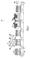
- FIG. 1 Is shown in a very schematic and nonlimiting an Automated Analyzer 10 according to the invention.
- the means 120 for suppressing the electrostatic charges comprise an ionizer 122 constituted here by an ionization ramp which is fed by conventional supply means not shown here.
Description
La présente invention concerne le domaine des appareils pour réaliser des analyses médicales.The present invention relates to the field of devices for performing medical analyzes.
Traditionnellement, de tels appareils, également appelés automates d'analyses, permettent d'automatiser certains protocoles, comme par exemple le pipetage de liquides dans des cartes gel. Ce protocole consiste à verser une quantité de liquide prédéterminée dans un puits réactionnel d'une carte gel contenant un ou plusieurs réactifs. Ce liquide peut par exemple être un échantillon sanguin, ou tout autre type de prélèvement humain.Traditionally, such devices, also known as automated analysis, allow to automate certain protocols, such as for example the pipetting of liquids in gel cards. This protocol consists of pouring a predetermined quantity of liquid into a reaction well of a gel card containing one or more reagents. This liquid may for example be a blood sample, or any other type of human sample.
De manière connue, une carte gel est un réceptacle contenant un ou plusieurs puits réactionnels qui sont initialement obturés par un opercule. Après avoir percé l'opercule et versé le liquide, des réactions chimiques se déroulent entre le liquide versé et le ou les réactifs de la carte.In known manner, a gel card is a receptacle containing one or more reaction wells which are initially closed by a lid. After having pierced the lid and poured the liquid, chemical reactions take place between the poured liquid and the reagent or reagents of the card.
Généralement, la quantité de liquide déversée est très petite, de l'ordre d'une dizaine de microlitres de sorte que l'on parle généralement de « dose ». Qui plus est, le remplissage des puits doit respecter certains critères de qualité. Parmi ces critères, on mentionnera pus particulièrement celui relatif à la création d'une poche d'air (air-gap en anglais) entre la dose de liquide dispensée dans le puits et le réactif préalablement présent au fond du puits, ainsi que le critère relatif à l'absence d'éclaboussures de liquide sur la paroi interne du puits. Les éclaboussures proviennent le plus souvent d'un fractionnement plus ou moins important, mais toujours aléatoire, de la dose de liquide dispensée.Generally, the quantity of spilled liquid is very small, of the order of ten microliters so that one generally speaks of "dose". In addition, the filling of wells must meet certain quality criteria. Among these criteria, we will mention more particularly that relating to the creation of an air-gap in English between the dose of liquid dispensed in the well and the reagent previously present at the bottom of the well, as well as the criterion relating to the absence of splash of liquid on the inner wall of the well. The splashes usually come from a more or less important but still random fractionation of the liquid dose dispensed.
La présence d'une poche d'air a pour effet d'interdire provisoirement le contact physique entre la dose de liquide dispensée et le réactif. Un intérêt est de maîtriser l'instant à partir duquel la réaction chimique doit débuter. En pratique, les cartes gel sont incubées et centrifugées après la dispense de la dose de liquide conduisant ainsi à la réaction chimique.The presence of an air pocket has the effect of temporarily prohibiting the physical contact between the dose of liquid dispensed and the reagent. An interest is to control the moment from which the chemical reaction must begin. In practice, the gel cards are incubated and centrifuged after dispensing the liquid dose thus leading to the chemical reaction.
L'absence d'éclaboussures est quant à elle nécessaire afin d'éviter qu'une fraction de la dose de liquide ne reste accrochée aux parois du puits et soit ainsi soustraite au mélange réactionnel incubé et centrifugé.The absence of splash is necessary in order to prevent a fraction of the liquid dose remains attached to the walls of the well and thus be subtracted from the incubated reaction mixture and centrifuged.
Pour résoudre le premier problème, le document
Cependant, cette solution présente plusieurs inconvénients : les accessoires doivent être achetés, stockés et manipulés. Qui plus est, l'installation des accessoires sur les cartes gel doit nécessairement se faire manuellement, ce qui se révèle malcommode et peu rapide.However, this solution has several disadvantages: the accessories must be purchased, stored and handled. What's more, the installation of the accessories on the gel cards must necessarily be done manually, which is inconvenient and not very fast.
Un but de la présente invention est de proposer un dispositif de remplissage d'au moins un réceptacle de type carte gel initialement fermé par un opercule, permettant un remplissage automatique tout en remédiant aux inconvénients précités.An object of the present invention is to provide a device for filling at least one card-type receptacle initially closed by a lid, allowing automatic filling while overcoming the aforementioned drawbacks.
L'invention atteint son but par le fait que le dispositif de remplissage comporte un organe de perçage pour perforer l'opercule, des moyens pour supprimer les charges électrostatiques susceptibles d'être portées par le réceptacle, et des moyens de remplissage pour remplir le réceptacle après perforation de l'opercule et suppression des charges électrostatiques.The invention achieves its goal by the fact that the filling device comprises a piercing member for perforating the cap, means for suppressing the electrostatic charges likely to be borne by the receptacle, and filling means for filling the receptacle. after perforation of the lid and removal of electrostatic charges.
Les inventeurs ont en effet constaté que la suppression des charges électrostatiques sur le réceptacle permet d'éviter nettement la formation d'éclaboussures sur les parois internes du réceptacle. En effet, il se trouve que les charges électrostatiques portées par le réceptacle ont tendance à disloquer la dose de liquide au moment où elle quitte les moyens de remplissage. Il s'ensuit que certaines fractions de la dose viennent se coller contre la paroi interne du réceptacle, en raison des forces d'attraction créées par les charges électrostatiques.The inventors have indeed found that the removal of electrostatic charges on the receptacle can significantly prevent the formation of splashes on the inner walls of the receptacle. Indeed, it turns out that the electrostatic charges carried by the receptacle tend to dislocate the liquid dose at the moment when it leaves the filling means. It follows that some fractions of the dose are sticking against the inner wall of the receptacle, due to the attractive forces created by the electrostatic charges.
On comprend donc que le dispositif de remplissage selon l'invention permet avantageusement d'éviter la formation d'éclaboussures. De plus, la présente invention ne nécessite pas l'utilisation de consommables contrairement aux dispositifs antérieurs. Un autre intérêt de la présente invention est qu'elle permet un remplissage automatique.It is thus clear that the filling device according to the invention advantageously makes it possible to avoid the formation of splashes. In addition, the present invention does not require the use of consumables unlike prior devices. Another advantage of the present invention is that it allows automatic filling.
Qui plus est, la formation de la poche d'air est favorisée par l'absence de force électrostatique tendant à dévier la dose lâchée par les moyens de remplissage.What is more, the formation of the air pocket is favored by the absence of electrostatic force tending to deflect the dose released by the filling means.
De préférence, le réceptacle est une carte, du type carte gel, qui comporte une pluralité de puits fermés par l'opercule, chacun des puits contenant un ou plusieurs réactifs.Preferably, the receptacle is a card, of the gel card type, which comprises a plurality of wells closed by the lid, each well containing one or more reagents.
Avantageusement, l'organe de perçage comporte une herse de perçage munie d'une pluralité de pointes de perçage qui sont destinées à pénétrer dans les puits en traversant l'opercule.Advantageously, the piercing member comprises a piercing harrow provided with a plurality of piercing tips which are intended to penetrate the wells through the lid.
Un intérêt de la herse est qu'elle permet de percer en une seule fois plusieurs trous dans l'opercule, ces trous étant ceux par lesquels les moyens de remplissage déversent le liquide dans les puits.One advantage of the harrow is that it allows to drill at one time several holes in the lid, these holes being those through which the filling means pour the liquid into the wells.
De préférence, la herse comporte autant de pointes que le nombre de puits de la carte gel, grâce à quoi, l'opération de perçage de l'opercule d'une carte gel est réalisée en une seule fois.Preferably, the harrow comprises as many tips as the number of wells of the gel card, whereby the piercing operation of the operculum of a gel card is performed at one time.
De manière particulièrement avantageuse, les moyens pour supprimer les charges électrostatiques comprennent un ioniseur. Ce dernier génère un flux d'ions de charge alternativement positive et négative, ce flux d'ions étant envoyé vers le réceptacle, de préférence après que l'opercule a été perforé. Cette alternance permet de supprimer les charges électrostatiques portées par les puits de la carte gel.Particularly advantageously, the means for suppressing the electrostatic charges comprise an ionizer. The latter generates a flow of alternately positive and negative charge ions, this flow of ions being sent to the receptacle, preferably after the operculum has been perforated. This alternation makes it possible to eliminate the electrostatic charges carried by the wells of the gel card.
De préférence, l'ioniseur est apte et destiné à générer un champ électrique produisant un effet corona. Cet effet corona, connu en soi, est également appelé effet couronne.Preferably, the ionizer is adapted and intended to generate an electric field producing a corona effect. This corona effect, known per se, is also called corona effect.
Selon un mode de réalisation préféré, le dispositif de remplissage présente une direction d'amenée des réceptacles vers l'organe de perçage et l'ioniseur est constitué d'au moins une rampe d'ionisation s'étendant transversalement par rapport à cette direction d'amenée. Cette rampe est de préférence disposée au plus près de la zone de perçage afin d'ioniser la carte gel aussitôt l'opercule percé.According to a preferred embodiment, the filling device has a direction of delivery of the receptacles to the piercing member and the ionizer is constituted by at least one ionization ramp extending transversely with respect to this direction of contact. 'feed. This ramp is preferably arranged as close to the piercing area to ionize the gel card immediately pierced operculum.
De plus, l'ioniseur comporte préférentiellement une pluralité d'électrodes visant une zone dans laquelle le réceptacle est destiné à se trouver lors du perçage de l'opercule dudit réceptacle.In addition, the ionizer preferably comprises a plurality of electrodes for an area in which the receptacle is intended to be during drilling of the cap of said receptacle.
Sans sortir du cadre de la présente invention, on pourrait également utiliser un ioniseur pourvu de moyens pour souffler l'air ionisé vers la carte gel.Without departing from the scope of the present invention, it would also be possible to use an ionizer provided with means for blowing the ionized air towards the gel card.
De préférence la rampe d'ionisation s'étend entre les deux bras mobiles qui portent la herse de perçage, grâce à quoi il est possible d'ioniser la carte gel immédiatement après l'opération de perçage.Preferably the ionization ramp extends between the two movable arms which carry the piercing harrow, whereby it is possible to ionize the gel card immediately after the piercing operation.
L'invention concerne également un automate d'analyses médicales pour l'analyse de réactions chimiques ayant lieu dans au moins un réceptacle qui comprend une pluralité de puits contenant un ou plusieurs réactifs tout en étant fermés par au moins un opercule ledit automate comportant un dispositif de remplissage selon l'invention, des moyens pour amener ledit réceptacle vers ledit dispositif de remplissage, et des moyens pour analyser les réactions chimiques susceptibles de se dérouler dans les puits du réceptacle après que les moyens de remplissage ont déversé une quantité de liquide dans chacun des puits.The invention also relates to a medical analysis automaton for the analysis of chemical reactions taking place in at least one receptacle which comprises a plurality of wells containing one or more reagents while being closed by at least one operculum said automaton comprising a device filling device according to the invention, means for bringing said receptacle to said filling device, and means for analyzing the chemical reactions that may take place in the wells of the receptacle after the filling means have poured a quantity of liquid into each Wells.
De préférence l'automate comporte une pluralité de réceptacles constitués par des cartes gel similaires ou différents les unes des autres.Preferably the automaton comprises a plurality of receptacles consisting of gel cards similar or different from each other.
Avantageusement, l'automate selon l'invention comporte en outre une station de contrôle pour vérifier le positionnement du liquide déversé dans les puits par les moyens de remplissage.Advantageously, the automaton according to the invention further comprises a control station for verifying the positioning of the liquid poured into the wells by the filling means.
De préférence, cette station de contrôle comporte une caméra ainsi que des moyens de traitement d'images permettant d'identifier la présence ou non d'une poche d'air et d'éventuelles éclaboussures.Preferably, this control station comprises a camera as well as image processing means making it possible to identify the presence or absence of an air pocket and possible splashing.
L'invention concerne également un procédé de remplissage d'un réceptacle de type carte gel muni d'une pluralité de puits fermés par un opercule, comprenant :
- une étape de perçage de l'opercule du réceptacle afin d'ouvrir les puits;
- une étape de suppression des charges électrostatiques susceptibles d'être portées par le réceptacle ; et
- une étape de remplissage au cours de laquelle une quantité de liquide est déversée dans chacun des puits du réceptacle.
- a step of piercing the lid of the receptacle to open the wells;
- a step of removing the electrostatic charges likely to be carried by the receptacle; and
- a filling step during which a quantity of liquid is poured into each well of the receptacle.
De préférence, ce procédé est mis en oeuvre par le dispositif de remplissage conforme à la présente invention.Preferably, this method is implemented by the filling device according to the present invention.
Avantageusement, l'étape de suppression des charges électrostatiques consiste à ioniser les puits du réceptacle en générant un champ électrique produisant un effet corona.Advantageously, the electrostatic charge elimination step consists in ionizing the wells of the receptacle by generating an electric field producing a corona effect.
De préférence, mais pas nécessairement, l'étape de suppression des charges électrostatiques est réalisée après l'étape de perçage. Un intérêt est de pouvoir ioniser l'air contenu à l'intérieur des puits.Preferably, but not necessarily, the electrostatic charge removal step is performed after the piercing step. An interest is to be able to ionize the air contained inside the wells.
Avantageusement, l'étape de remplissage des puits est réalisée avec au moins une pipette, et lors de cette étape de remplissage, ladite pipette s'étend de manière coaxiale à l'un des puits.Advantageously, the step of filling the wells is carried out with at least one pipette, and during this filling step, said pipette extends coaxially with one of the wells.
Un intérêt est d'éviter que l'extrémité de la pipette ne vienne en contact avec des gouttelettes de réactif pouvant se trouver sur la paroi interne du puits, et donc d'éviter toute contamination de la pipette.An interest is to prevent the end of the pipette comes into contact with droplets of reagent may be on the inner wall of the well, and thus to avoid contamination of the pipette.
Selon l'invention, un moyen complémentaire d'éviter la contamination de la pipette est de placer l'extrémité inférieure de la pipette légèrement en dessous de l'opercule lors de l'étape de remplissage. De préférence, l'extrémité inférieure de la pipette est placée à quelques millimètres sous l'opercule.According to the invention, a complementary means of avoiding contamination of the pipette is to place the lower end of the pipette slightly below the lid during the filling step. Preferably, the lower end of the pipette is placed a few millimeters below the cap.
Préférentiellement, lors de l'étape de remplissage, on crée une poche d'air (air-gap) entre le liquide déversé et un autre liquide préalablement présent dans les puits. Autrement dit, on crée une poche d'air entre le réactif contenu dans chacun des puits et les doses déversées.Preferably, during the filling step, an air-gap is created between the spilled liquid and another liquid previously present in the wells. In other words, a pocket of air is created between the reagent contained in each of the wells and the spilled doses.
Enfin et de manière avantageuse, le procédé selon l'invention comporte en outre une étape de vérification du positionnement du liquide déversé à l'issue de l'étape de remplissage. On vérifie principalement la bonne réalisation des poches d'air.Finally and advantageously, the method according to the invention also comprises a step of verifying the positioning of the spilled liquid at the end of the filling step. We mainly check the good realization of the air pockets.
L'invention sera mieux comprise et ses avantages apparaîtront mieux à la lecture de la description détaillée qui suit, d'un mode de réalisation représenté à titre d'exemple non limitatif. La description se réfère aux dessins, sur lesquels :
- la
figure 1 illustre de manière schématique un automate d'analyses médicales conforme à l'invention, qui comporte un dispositif de remplissage selon l'invention ; - la
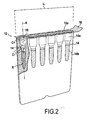
figure 2 est une vue de face d'un réceptacle destiné à être utilisé avec l'automate de lafigure 1 ; - la
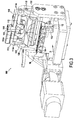
figure 3 est une vue en perspective d'un mode de réalisation préféré du dispositif de remplissage selon l'invention ; - la
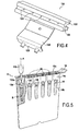
figure 4 est une vue de détail de la rampe d'ionisation du dispositif de remplissage de lafigure 3 ; et - la
figure 5 montre la formation d'une poche d'air entre le réactif contenu dans un puits du réceptacle de lafigure 2 et une dose de liquide dispensée par une pipette de l'automate de lafigure 1 .
- the
figure 1 schematically illustrates a medical analysis automaton according to the invention, which comprises a filling device according to the invention; - the
figure 2 is a front view of a receptacle intended to be used with the automaton of thefigure 1 ; - the
figure 3 is a perspective view of a preferred embodiment of the filling device according to the invention; - the
figure 4 is a detailed view of the ionization ramp of the filling device of thefigure 3 ; and - the
figure 5 shows the formation of an air pocket between the reagent contained in a well of the receptacle of thefigure 2 and a dose of liquid dispensed by a pipette from the automaton of thefigure 1 .
Sur la
Cet automate 10 utilise des réceptacles consommables, en l'espèce des cartes gel 12 munies de puits 14, bien connues par ailleurs. En se référant à la
Comme on le comprend à l'aide de la
Plus précisément, chaque puits 14 est constitué d'une cavité supérieure 14a de forme sensiblement cylindrique reliée à une cavité inférieure 14b également de forme sensiblement cylindrique par l'intermédiaire d'une cavité intermédiaire tronconique. La cavité supérieure 14a présente un diamètre sensiblement plus grand que celui de la cavité inférieure 14b, et les cavités supérieure 14a et inférieure 14b sont coaxiales d'axe commun A. Comme on le voit sur la
Il se trouve que les cartes gel 12, réalisées en matière plastique, ont une propension à porter des charges électrostatiques C+, C-, on pense qu'elles sont générées lors des chocs que peuvent subir les cartes gel 12 lors de leur manutention.It turns out that the
En se référant à nouveau à la
Considérée selon cette direction d'amenée D, l'automate 10 comporte successivement un dispositif de remplissage 100 conforme à l'invention, une station de contrôle 200 pour vérifier le positionnement du liquide déversé dans les puits par le dispositif de remplissage, une roue centrifuge 300 puis des moyens 400 pour analyser les réactions chimiques susceptibles de se dérouler dans les puits de la carte gel.Considered according to this feeding direction D, the
Les cartes gel 12 sont tout d'abord amenées vers le dispositif de remplissage 100, ce dernier étant destiné à remplir les puits des cartes gel 12 avec un liquide dans une quantité prédéterminée.The
Pour ce faire, le dispositif de remplissage 100 selon l'invention comporte tout d'abord un organe de perçage 110 pour perforer les opercules 18 des cartes gel.To do this, the filling
Selon un aspect essentiel de l'invention, le dispositif de remplissage 100 comporte en outre des moyens 120 pour supprimer les charges électrostatiques susceptibles d'être portées par les cartes gel. Et bien évidemment, le dispositif de remplissage comporte également des moyens de remplissage 130 pour remplir les puits des cartes gel après perforation de l'opercule et suppression des charges électrostatiques. Il est précisé que, selon le mode préféré de l'invention, les moyens de remplissage 140 sont automatiques. Toutefois et sans sortir du cadre de la présente invention, ils pourraient aussi être constitués d'une pipette manuelle manipulée par un opérateur.According to an essential aspect of the invention, the filling
L'organe de perçage 110 et les moyens 120 pour supprimer les charges électrostatiques vont tout d'abord être décrits plus en détail à l'aide des
L'organe de perçage 110 comporte une herse de perçage 112 qui est munie de six pointes 114, ces pointes étant destinées à pénétrer dans les puits de la carte gel en traversant l'opercule 18 de façon à créer une série de trous 17 dans l'opercule. Les cartes gel 12 comportant également six puits 14, on comprend que la herse 112 permet de réaliser en une seule fois six trous 17 dans l'opercule de chacune des cartes gel 12. The piercing
Comme on le voit sur la
Qui plus est, les pointes 114 de la herse 112 présentent de préférence des méplats 114a afin de favoriser le perçage de l'opercule 18. Moreover, the
Par ailleurs, une paire de lames-ressort 116 s'étendant entre les pointes 114 est prévue pour faciliter le dégagement de la herse de perçage 112 après la perforation de l'opercule 18. Furthermore, a pair of
Enfin, on précise que la herse 112 est verrouillée à un support de herse 113 par un organe de verrouillage 118 permettant de démonter la herse 112. Par ailleurs, ce support de herse 112 comporte deux bras mobiles 113a, 113b entre lesquels s'étend la herse 112, ces bras étant quant à eux reliés à des bielles 115 pivotantes qui permettent d'amener la herse 112, selon un mouvement de translation circulaire, depuis une position de repos (représentée sur la
Selon un aspect avantageux de l'invention, les moyens 120 pour supprimer les charges électrostatiques comprennent un ioniseur 122 constitué ici par une rampe d'ionisation qui est alimentée par des moyens d'alimentation conventionnels non représentés ici.According to an advantageous aspect of the invention, the
Cette rampe d'ionisation 122 est immobile par rapport à l'automate et s'étend transversalement par rapport à la direction d'amenée D entre les bras 113a et 113b du support de herse 113. Comme on le voit sur la
Par ailleurs, on voit sur la
En se référant maintenant à la
On va maintenant expliquer le procédé de remplissage mis en oeuvre par le dispositif de remplissage 100 selon l'invention.We will now explain the filling process implemented by the filling
Comme on le voit sur la
Lorsque l'organe de perçage 110 est actionné, la herse 112 bascule dans sa position de travail selon le mouvement de translation circulaire décrit ci-dessus, de sorte que les pointes 114 de la herse 112 viennent perforer l'opercule 18. Ensuite, la herse 112 est ramenée dans sa position de repos telle que représentée sur la
Après cette étape de perçage, la rampe d'ionisation est activée de manière à générer un champ électrique à effet corona autour des puits 14. Comme expliqué ci-dessus, ce champ électrique à effet corona génère un air ionisé qui a pour effet de supprimer les charges électrostatiques C+, C- éventuellement portées par les puits des cartes gel 12. De préférence, la durée d'ionisation des puits 14 est comprise entre 1 et 1,5 secondes.After this piercing step, the ionization ramp is activated so as to generate a corona electric field around the
Après l'étape d'ionisation, la carte gel 12 est amenée vers les moyens de remplissage 170. Ces derniers comportent au moins une pipette 132 visible sur la
Ensuite la pipette 132 déverse une dose 134 de liquide, soit environ 10 µl, dans la cavité supérieure 14a, comme cela a été représenté sur la
Très préférentiellement, on fait en sorte de créer une poche d'air 136 entre la dose 134 et le réactif contenu dans la cavité inférieure 14b des puits 14. Cette poche d'air se situe essentiellement en bas de la cavité intermédiaire tronconique.Very preferably, it is arranged to create an
A l'issue de l'étape de remplissage, la carte gel 12 est amenée dans la station de contrôle 200 afin de vérifier la présence de poches d'air 136. At the end of the filling step, the
Après cela, la carte gel 12 est incubée puis centrifugée grâce à la roue centrifuge 300. After that, the
Le résultat des réactions chimiques ayant lieu dans les puits 14 est ensuite analysé à l'aide des moyens 400 d'analyse de réactions chimiques. De tels moyens, connus par ailleurs, comportent généralement un lecteur permettant de visualiser le résultat de la ou des réactions dans les puits 14 de la carte gel 12. The result of the chemical reactions taking place in the
Claims (17)
- A device (100) for filling at least one receptacle (12) of the gel card type initially sealed by a cap (18), said device being characterized in that includes a piercing member (110) to perforate the cap, means (120) for eliminating the electrostatic charges that may be borne by the receptacle, and filling means (130) to fill the receptacle after perforation of the cap and elimination of the electrostatic charges (C+, C-).
- The filling device according to claim 1, characterized in that the receptacle is a card (12), which includes a plurality of wells (14) sealed by the cap (18), each of the wells containing one or more reagents (R).
- The filling device according to claim 2, characterized in that the piercing member (120) includes a piercing rake (112) provided with a plurality of piercing tips (114) that are intended to penetrate the wells while passing through the cap.
- The filling device according to claim 2 or 3, characterized in that the filling means comprise at least one pipette (132).
- The filling device according to any one of claims 1 to 4, characterized in that the means for eliminating the electrostatic charges (120) comprise an ionizer (122).
- The filling device according to claim 5, characterized in that it has an intake direction (D) for the receptacle toward the piercing member, and in that the ionizer is made up of an ionization ramp (122) extending transversely relative to said intake direction.
- The filling device according to claim 5 or 6, characterized in that the ionizer (122) includes a plurality of electrodes (134) targeting a zone in which the receptacle (12) is intended to be located during piercing of the cap of said receptacle.
- The filling device according to any one of claims 5 to 7, characterized in that the ionizer (122) is intended to generate an electrical field (E) producing a corona effect.
- A medical analysis machine (10) for analyzing chemical reactions taking place in at least one receptacle (12) that comprises a plurality of wells (14) containing one or more reagents while being sealed by at least one cap (18), said machine including a filling device (100) according to any one of claims 1 to 8, means (50) for bringing said receptacle toward said filling device, and means (400) for analyzing the chemical reactions that can occur in the wells of the receptacle after the filling means (130) have poured a quantity of liquid into each of the wells.
- The machine according to claim 9, characterized in that it also includes a checking station (200) to verify the positioning of the liquid poured into the wells by the filling means (130).
- A method of filling a receptacle (12) of the gel card type provided with a plurality of wells sealed by a cap, characterized in that it comprises:- a step of piercing the cap of the receptacle in order to open the well;- a step of eliminating electrostatic charges that may be borne by the receptacle; and- a filling step during which a quantity of liquid is poured into each of the wells of the receptacle.
- The filling method according to claim 11, characterized in that the step for eliminating the electrostatic charges consists of ionizing the well of the receptacle by generating an electrical field producing a corona effect.
- The filling method according to claim 11 or 12, characterized in that the step of eliminating the electrostatic charges is carried out after the piercing step.
- The filling method according to any one of claims 11 to 13, characterized in that the step of filling the wells is carried out with at least one pipette, and in that, during said filling step, said pipette extends coaxially to one of the wells.
- The filling method according to any one of claims 11 to 14, characterized in that the filling step is carried out with at least one pipette having a lower end, and in that, during said filling step, the lower end is placed slightly below the cap.
- The filling method according to any one of claims 11 to 15, characterized in that, during the filling step, an air gap is created between the poured liquid and another liquid previously present in the wells.
- The filling method according to any one of claims 11 to 16, characterized in that it further includes a step of verifying the positioning of the liquid poured at the end of the filling step.
Priority Applications (1)
| Application Number | Priority Date | Filing Date | Title |
|---|---|---|---|
| PL10717693T PL2417028T3 (en) | 2009-04-08 | 2010-03-31 | Device for filling a card typ gel, having means for ionisation |
Applications Claiming Priority (2)
| Application Number | Priority Date | Filing Date | Title |
|---|---|---|---|
| FR0952290A FR2944263B1 (en) | 2009-04-08 | 2009-04-08 | FILLING DEVICE FOR GEL CARDS COMPRISING A IONIZER |
| PCT/FR2010/050602 WO2010116069A2 (en) | 2009-04-08 | 2010-03-31 | Gel card filling device comprising an ionizer |
Publications (2)
| Publication Number | Publication Date |
|---|---|
| EP2417028A2 EP2417028A2 (en) | 2012-02-15 |
| EP2417028B1 true EP2417028B1 (en) | 2014-08-20 |
Family
ID=41327287
Family Applications (1)
| Application Number | Title | Priority Date | Filing Date |
|---|---|---|---|
| EP10717693.5A Active EP2417028B1 (en) | 2009-04-08 | 2010-03-31 | Device for filling a card typ gel, having means for ionisation |
Country Status (15)
| Country | Link |
|---|---|
| US (2) | US9146249B2 (en) |
| EP (1) | EP2417028B1 (en) |
| JP (1) | JP5596781B2 (en) |
| CN (1) | CN102459001B (en) |
| AU (1) | AU2010233575B2 (en) |
| BR (1) | BRPI1015210B1 (en) |
| CA (1) | CA2758226C (en) |
| ES (1) | ES2524329T3 (en) |
| FR (1) | FR2944263B1 (en) |
| HK (1) | HK1170707A1 (en) |
| MX (1) | MX336458B (en) |
| PL (1) | PL2417028T3 (en) |
| PT (1) | PT2417028E (en) |
| RU (1) | RU2539935C2 (en) |
| WO (1) | WO2010116069A2 (en) |
Families Citing this family (11)
| Publication number | Priority date | Publication date | Assignee | Title |
|---|---|---|---|---|
| FR2972432B1 (en) | 2011-03-10 | 2014-06-13 | Bio Rad Pasteur | GEL-TYPE RECEPTACLE HAVING A OPERATOR COMPRISING A PREDECTOR |
| FR2972436B1 (en) * | 2011-03-10 | 2013-04-12 | Bio Rad Pasteur | STATION OF SELECTIVE DETACHING OF GEL CARDS |
| DE102011113358A1 (en) * | 2011-09-15 | 2013-03-21 | Groninger & Co. Gmbh | Method and device for filling and closing pharmaceutical objects |
| FR2987896B1 (en) * | 2012-03-08 | 2014-04-25 | Noviloire | MEDICAL ANALYSIS AUTOMATE AND CORRESPONDING METHOD |
| FR2991311B1 (en) * | 2012-05-31 | 2014-07-04 | Noviloire | DRILLING SYSTEM OF A OPERATOR |
| CN103592448A (en) * | 2013-11-22 | 2014-02-19 | 合肥天一生物技术研究所 | Full-automatic centrifugal interpretoscope |
| US10191074B2 (en) * | 2014-07-18 | 2019-01-29 | Hitachi High-Technologies Corporation | Automatic analyzing apparatus |
| CN105964419A (en) * | 2016-07-01 | 2016-09-28 | 江苏克莱斯克生物技术有限公司 | Medical centrifuge |
| CN106153962B (en) * | 2016-07-22 | 2018-01-30 | 嘉兴科瑞迪医疗器械有限公司 | A kind of micro-column gel card automatic puncturing device |
| JP2022011167A (en) * | 2020-06-29 | 2022-01-17 | 澁谷工業株式会社 | Liquid suction and discharge device |
| WO2023182167A1 (en) * | 2022-03-22 | 2023-09-28 | 富士フイルム株式会社 | Inspection device |
Family Cites Families (19)
| Publication number | Priority date | Publication date | Assignee | Title |
|---|---|---|---|---|
| DE2151729C3 (en) * | 1971-10-18 | 1978-11-02 | Rota Apparate- Und Maschinenbau Dr. Hennig Kg, 7867 Wehr | Device for checking an ampoule opening |
| JPH07119765B2 (en) * | 1985-08-30 | 1995-12-20 | 東ソー株式会社 | Automatic immunoassay device |
| JPH0240562A (en) * | 1988-07-30 | 1990-02-09 | Shimadzu Corp | Method and apparatus for separate injection of liquid |
| JPH0618968A (en) | 1991-10-02 | 1994-01-28 | Mitsubishi Electric Corp | Swiveling image pickup device |
| JPH0618968U (en) * | 1992-01-31 | 1994-03-11 | 株式会社日立製作所 | Automatic analyzer with static eliminator |
| US5780248A (en) * | 1993-07-15 | 1998-07-14 | Ortho Diagnostic Systems, Inc. | Foil sealed cassette for agglutination reactions and liner therefor |
| ES2150339B1 (en) * | 1997-07-30 | 2001-06-01 | Grifols Grupo Sa | "UNIVERSAL MACHINE FOR CLINICAL ANALYSIS". |
| US20020001544A1 (en) * | 1997-08-28 | 2002-01-03 | Robert Hess | System and method for high throughput processing of droplets |
| US7470547B2 (en) * | 2003-07-31 | 2008-12-30 | Biodot, Inc. | Methods and systems for dispensing sub-microfluidic drops |
| US6575208B2 (en) * | 2000-04-04 | 2003-06-10 | M.L.I.S. Projects Ltd. | Method and apparatus for filling a multi-compartment container |
| JP4193566B2 (en) * | 2003-05-06 | 2008-12-10 | 東ソー株式会社 | Automatic analyzer |
| FR2858057B1 (en) * | 2003-07-21 | 2006-05-26 | Abx Sa | QUALITY CONTROL DEVICE FOR BLOOD ANALYZER OPERATING IN WHOLE BLOOD |
| JP4345060B2 (en) * | 2004-11-30 | 2009-10-14 | Smc株式会社 | Ionizer |
| EP1872139A2 (en) * | 2005-04-09 | 2008-01-02 | Cell Biosciences, Inc. | Automated micro-volume assay system |
| GB0510057D0 (en) * | 2005-05-17 | 2005-06-22 | Glaxosmithkline Biolog Sa | Novel device |
| JP2008102032A (en) * | 2006-10-19 | 2008-05-01 | Olympus Corp | Rack conveyance mechanism and automatic analyzer |
| JP2009030987A (en) * | 2007-07-24 | 2009-02-12 | Canon Inc | Liquid sample dispenser and biochemical reaction apparatus |
| US7823447B2 (en) * | 2007-09-17 | 2010-11-02 | Perkinelmer Las, Inc. | Method and apparatus for sensing a liquid level |
| JP2009074911A (en) * | 2007-09-20 | 2009-04-09 | Sysmex Corp | Pipette chip supply device and specimen analyzer |
-
2009
- 2009-04-08 FR FR0952290A patent/FR2944263B1/en not_active Expired - Fee Related
-
2010
- 2010-03-31 ES ES10717693.5T patent/ES2524329T3/en active Active
- 2010-03-31 EP EP10717693.5A patent/EP2417028B1/en active Active
- 2010-03-31 MX MX2011010532A patent/MX336458B/en unknown
- 2010-03-31 BR BRPI1015210-5A patent/BRPI1015210B1/en active IP Right Grant
- 2010-03-31 PT PT107176935T patent/PT2417028E/en unknown
- 2010-03-31 WO PCT/FR2010/050602 patent/WO2010116069A2/en active Application Filing
- 2010-03-31 RU RU2011141735/13A patent/RU2539935C2/en active
- 2010-03-31 CA CA2758226A patent/CA2758226C/en active Active
- 2010-03-31 US US13/263,394 patent/US9146249B2/en active Active
- 2010-03-31 AU AU2010233575A patent/AU2010233575B2/en active Active
- 2010-03-31 PL PL10717693T patent/PL2417028T3/en unknown
- 2010-03-31 JP JP2012504048A patent/JP5596781B2/en active Active
- 2010-03-31 CN CN201080025318.5A patent/CN102459001B/en active Active
-
2012
- 2012-11-15 HK HK12111625.6A patent/HK1170707A1/en unknown
-
2015
- 2015-09-22 US US14/861,233 patent/US9410974B2/en active Active
Also Published As
| Publication number | Publication date |
|---|---|
| HK1170707A1 (en) | 2013-03-08 |
| CN102459001B (en) | 2015-04-01 |
| JP2012523555A (en) | 2012-10-04 |
| EP2417028A2 (en) | 2012-02-15 |
| FR2944263A1 (en) | 2010-10-15 |
| CA2758226C (en) | 2016-10-11 |
| MX336458B (en) | 2016-01-20 |
| WO2010116069A3 (en) | 2010-12-16 |
| BRPI1015210A2 (en) | 2018-07-10 |
| US20120051975A1 (en) | 2012-03-01 |
| CN102459001A (en) | 2012-05-16 |
| BRPI1015210B1 (en) | 2020-10-27 |
| WO2010116069A2 (en) | 2010-10-14 |
| JP5596781B2 (en) | 2014-09-24 |
| RU2539935C2 (en) | 2015-01-27 |
| CA2758226A1 (en) | 2010-10-14 |
| ES2524329T3 (en) | 2014-12-05 |
| FR2944263B1 (en) | 2015-07-24 |
| AU2010233575A1 (en) | 2011-11-03 |
| US20160011226A1 (en) | 2016-01-14 |
| MX2011010532A (en) | 2012-01-12 |
| RU2011141735A (en) | 2013-05-20 |
| PT2417028E (en) | 2014-11-25 |
| US9410974B2 (en) | 2016-08-09 |
| US9146249B2 (en) | 2015-09-29 |
| PL2417028T3 (en) | 2015-02-27 |
| AU2010233575B2 (en) | 2016-06-23 |
Similar Documents
| Publication | Publication Date | Title |
|---|---|---|
| EP2417028B1 (en) | Device for filling a card typ gel, having means for ionisation | |
| EP2855341B1 (en) | System for piercing a membrane | |
| CA2426840C (en) | Device for improving extraction of a food substance contained in a refill element | |
| EP2821146B1 (en) | Shaking and centrifugation device and method | |
| WO2013178927A1 (en) | Dispenser for viscous products | |
| FR2969128A1 (en) | CAP FOR CLOSING A CONTAINER | |
| EP3383341B1 (en) | Perforating needle for flask with septum | |
| EP1993733B1 (en) | Device, use and method for drawing off a liquid | |
| EP2683482B1 (en) | Apparatus for removing the cover of receptacles of gel card type | |
| WO2023227637A1 (en) | Device for dispensing animal feed, and method for dispensing wet feed implemented by a device of this kind | |
| EP2683647B1 (en) | Station for the selective uncapping of gel cards | |
| FR3069231B1 (en) | METHOD FOR OPENING A FOOD CAPSULE | |
| FR2909272A1 (en) | DEVICE FOR OPENING A BIVALVE | |
| WO2023242140A1 (en) | Water treatment apparatus provided with a filter cartridge and with a rotary stirrer | |
| EP2732743A1 (en) | Drawer-shaped reservoir for collecting spent coffee grounds | |
| FR3064173A1 (en) | ANIMAL SEMEN CONDITIONING STRAIN TREATMENT PLANT, COMPRISING A DEVICE FOR FEEDING AND POSITIONING THESE FLAKES | |
| FR3011827A1 (en) | DEVICE FOR DISPENSING DOSES OF PRODUCT FOR INFUSION. | |
| EP4304949A1 (en) | Opening device with an integrated straw, and method for manufacturing the device | |
| EP1548520B1 (en) | Tonercartridge with unique reloading and method therefor | |
| EP3906067A1 (en) | Capsule for aromatherapy composition and diffusion device for using such a capsule | |
| EP2499945A1 (en) | Individual elements dispensing device | |
| FR3098805A1 (en) | Ejection finger for device for supplying sorted closure elements and method of manufacturing by molding | |
| WO2009056770A1 (en) | Metering device adaptable to a container | |
| FR2872797A1 (en) | Blister strip for inhaler has separate blisters and single closing layer for the blister cavities | |
| FR3057474A1 (en) | DISTRIBUTOR FILLING CARTRIDGE. |
Legal Events
| Date | Code | Title | Description |
|---|---|---|---|
| PUAI | Public reference made under article 153(3) epc to a published international application that has entered the european phase |
Free format text: ORIGINAL CODE: 0009012 |
|
| 17P | Request for examination filed |
Effective date: 20111107 |
|
| AK | Designated contracting states |
Kind code of ref document: A2 Designated state(s): AT BE BG CH CY CZ DE DK EE ES FI FR GB GR HR HU IE IS IT LI LT LU LV MC MK MT NL NO PL PT RO SE SI SK SM TR |
|
| DAX | Request for extension of the european patent (deleted) | ||
| REG | Reference to a national code |
Ref country code: DE Ref legal event code: R079 Ref document number: 602010018377 Country of ref document: DE Free format text: PREVIOUS MAIN CLASS: B65B0003000000 Ipc: G01N0035100000 |
|
| RIC1 | Information provided on ipc code assigned before grant |
Ipc: G01N 35/04 20060101ALI20140129BHEP Ipc: G01N 35/10 20060101AFI20140129BHEP Ipc: B65B 3/00 20060101ALI20140129BHEP |
|
| GRAP | Despatch of communication of intention to grant a patent |
Free format text: ORIGINAL CODE: EPIDOSNIGR1 |
|
| INTG | Intention to grant announced |
Effective date: 20140416 |
|
| RIN1 | Information on inventor provided before grant (corrected) |
Inventor name: BUFFIERE, FREDERIC Inventor name: BRISEBRAT, JEAN-MICHEL Inventor name: PETIT, SERGE |
|
| GRAS | Grant fee paid |
Free format text: ORIGINAL CODE: EPIDOSNIGR3 |
|
| GRAA | (expected) grant |
Free format text: ORIGINAL CODE: 0009210 |
|
| AK | Designated contracting states |
Kind code of ref document: B1 Designated state(s): AT BE BG CH CY CZ DE DK EE ES FI FR GB GR HR HU IE IS IT LI LT LU LV MC MK MT NL NO PL PT RO SE SI SK SM TR |
|
| REG | Reference to a national code |
Ref country code: GB Ref legal event code: FG4D Free format text: NOT ENGLISH |
|
| REG | Reference to a national code |
Ref country code: CH Ref legal event code: EP |
|
| REG | Reference to a national code |
Ref country code: AT Ref legal event code: REF Ref document number: 683741 Country of ref document: AT Kind code of ref document: T Effective date: 20140915 |
|
| REG | Reference to a national code |
Ref country code: IE Ref legal event code: FG4D Free format text: LANGUAGE OF EP DOCUMENT: FRENCH |
|
| REG | Reference to a national code |
Ref country code: DE Ref legal event code: R096 Ref document number: 602010018377 Country of ref document: DE Effective date: 20141002 |
|
| REG | Reference to a national code |
Ref country code: PT Ref legal event code: SC4A Free format text: AVAILABILITY OF NATIONAL TRANSLATION Effective date: 20141117 |
|
| REG | Reference to a national code |
Ref country code: ES Ref legal event code: FG2A Ref document number: 2524329 Country of ref document: ES Kind code of ref document: T3 Effective date: 20141205 |
|
| REG | Reference to a national code |
Ref country code: CH Ref legal event code: NV Representative=s name: MICHELI AND CIE SA, CH |
|
| REG | Reference to a national code |
Ref country code: NL Ref legal event code: T3 |
|
| REG | Reference to a national code |
Ref country code: AT Ref legal event code: MK05 Ref document number: 683741 Country of ref document: AT Kind code of ref document: T Effective date: 20140820 |
|
| REG | Reference to a national code |
Ref country code: LT Ref legal event code: MG4D |
|
| PG25 | Lapsed in a contracting state [announced via postgrant information from national office to epo] |
Ref country code: LT Free format text: LAPSE BECAUSE OF FAILURE TO SUBMIT A TRANSLATION OF THE DESCRIPTION OR TO PAY THE FEE WITHIN THE PRESCRIBED TIME-LIMIT Effective date: 20140820 Ref country code: SE Free format text: LAPSE BECAUSE OF FAILURE TO SUBMIT A TRANSLATION OF THE DESCRIPTION OR TO PAY THE FEE WITHIN THE PRESCRIBED TIME-LIMIT Effective date: 20140820 Ref country code: BG Free format text: LAPSE BECAUSE OF FAILURE TO SUBMIT A TRANSLATION OF THE DESCRIPTION OR TO PAY THE FEE WITHIN THE PRESCRIBED TIME-LIMIT Effective date: 20141120 Ref country code: NO Free format text: LAPSE BECAUSE OF FAILURE TO SUBMIT A TRANSLATION OF THE DESCRIPTION OR TO PAY THE FEE WITHIN THE PRESCRIBED TIME-LIMIT Effective date: 20141120 Ref country code: GR Free format text: LAPSE BECAUSE OF FAILURE TO SUBMIT A TRANSLATION OF THE DESCRIPTION OR TO PAY THE FEE WITHIN THE PRESCRIBED TIME-LIMIT Effective date: 20141121 |
|
| PG25 | Lapsed in a contracting state [announced via postgrant information from national office to epo] |
Ref country code: HR Free format text: LAPSE BECAUSE OF FAILURE TO SUBMIT A TRANSLATION OF THE DESCRIPTION OR TO PAY THE FEE WITHIN THE PRESCRIBED TIME-LIMIT Effective date: 20140820 Ref country code: IS Free format text: LAPSE BECAUSE OF FAILURE TO SUBMIT A TRANSLATION OF THE DESCRIPTION OR TO PAY THE FEE WITHIN THE PRESCRIBED TIME-LIMIT Effective date: 20141220 Ref country code: AT Free format text: LAPSE BECAUSE OF FAILURE TO SUBMIT A TRANSLATION OF THE DESCRIPTION OR TO PAY THE FEE WITHIN THE PRESCRIBED TIME-LIMIT Effective date: 20140820 Ref country code: LV Free format text: LAPSE BECAUSE OF FAILURE TO SUBMIT A TRANSLATION OF THE DESCRIPTION OR TO PAY THE FEE WITHIN THE PRESCRIBED TIME-LIMIT Effective date: 20140820 |
|
| REG | Reference to a national code |
Ref country code: PL Ref legal event code: T3 |
|
| PG25 | Lapsed in a contracting state [announced via postgrant information from national office to epo] |
Ref country code: CZ Free format text: LAPSE BECAUSE OF FAILURE TO SUBMIT A TRANSLATION OF THE DESCRIPTION OR TO PAY THE FEE WITHIN THE PRESCRIBED TIME-LIMIT Effective date: 20140820 Ref country code: RO Free format text: LAPSE BECAUSE OF FAILURE TO SUBMIT A TRANSLATION OF THE DESCRIPTION OR TO PAY THE FEE WITHIN THE PRESCRIBED TIME-LIMIT Effective date: 20140820 Ref country code: EE Free format text: LAPSE BECAUSE OF FAILURE TO SUBMIT A TRANSLATION OF THE DESCRIPTION OR TO PAY THE FEE WITHIN THE PRESCRIBED TIME-LIMIT Effective date: 20140820 Ref country code: DK Free format text: LAPSE BECAUSE OF FAILURE TO SUBMIT A TRANSLATION OF THE DESCRIPTION OR TO PAY THE FEE WITHIN THE PRESCRIBED TIME-LIMIT Effective date: 20140820 Ref country code: SK Free format text: LAPSE BECAUSE OF FAILURE TO SUBMIT A TRANSLATION OF THE DESCRIPTION OR TO PAY THE FEE WITHIN THE PRESCRIBED TIME-LIMIT Effective date: 20140820 |
|
| PGFP | Annual fee paid to national office [announced via postgrant information from national office to epo] |
Ref country code: IE Payment date: 20150327 Year of fee payment: 6 Ref country code: FI Payment date: 20150327 Year of fee payment: 6 Ref country code: MC Payment date: 20150305 Year of fee payment: 6 |
|
| REG | Reference to a national code |
Ref country code: DE Ref legal event code: R097 Ref document number: 602010018377 Country of ref document: DE |
|
| PLBE | No opposition filed within time limit |
Free format text: ORIGINAL CODE: 0009261 |
|
| STAA | Information on the status of an ep patent application or granted ep patent |
Free format text: STATUS: NO OPPOSITION FILED WITHIN TIME LIMIT |
|
| 26N | No opposition filed |
Effective date: 20150521 |
|
| PG25 | Lapsed in a contracting state [announced via postgrant information from national office to epo] |
Ref country code: LU Free format text: LAPSE BECAUSE OF FAILURE TO SUBMIT A TRANSLATION OF THE DESCRIPTION OR TO PAY THE FEE WITHIN THE PRESCRIBED TIME-LIMIT Effective date: 20150331 |
|
| REG | Reference to a national code |
Ref country code: CH Ref legal event code: PL |
|
| PG25 | Lapsed in a contracting state [announced via postgrant information from national office to epo] |
Ref country code: SI Free format text: LAPSE BECAUSE OF FAILURE TO SUBMIT A TRANSLATION OF THE DESCRIPTION OR TO PAY THE FEE WITHIN THE PRESCRIBED TIME-LIMIT Effective date: 20140820 |
|
| REG | Reference to a national code |
Ref country code: CH Ref legal event code: AECN Free format text: LE BREVET A ETE REACTIVE SELON LA DEMANDE DE POURSUITE DE LA PROCEDURE DU 01.12.2015. |
|
| REG | Reference to a national code |
Ref country code: FR Ref legal event code: PLFP Year of fee payment: 7 |
|
| PGFP | Annual fee paid to national office [announced via postgrant information from national office to epo] |
Ref country code: PT Payment date: 20160304 Year of fee payment: 7 |
|
| PG25 | Lapsed in a contracting state [announced via postgrant information from national office to epo] |
Ref country code: FI Free format text: LAPSE BECAUSE OF NON-PAYMENT OF DUE FEES Effective date: 20160331 Ref country code: MC Free format text: LAPSE BECAUSE OF NON-PAYMENT OF DUE FEES Effective date: 20160331 |
|
| REG | Reference to a national code |
Ref country code: IE Ref legal event code: MM4A |
|
| PGFP | Annual fee paid to national office [announced via postgrant information from national office to epo] |
Ref country code: MT Payment date: 20150516 Year of fee payment: 6 |
|
| PG25 | Lapsed in a contracting state [announced via postgrant information from national office to epo] |
Ref country code: IE Free format text: LAPSE BECAUSE OF NON-PAYMENT OF DUE FEES Effective date: 20160331 |
|
| REG | Reference to a national code |
Ref country code: FR Ref legal event code: PLFP Year of fee payment: 8 |
|
| PG25 | Lapsed in a contracting state [announced via postgrant information from national office to epo] |
Ref country code: HU Free format text: LAPSE BECAUSE OF FAILURE TO SUBMIT A TRANSLATION OF THE DESCRIPTION OR TO PAY THE FEE WITHIN THE PRESCRIBED TIME-LIMIT; INVALID AB INITIO Effective date: 20100331 Ref country code: SM Free format text: LAPSE BECAUSE OF FAILURE TO SUBMIT A TRANSLATION OF THE DESCRIPTION OR TO PAY THE FEE WITHIN THE PRESCRIBED TIME-LIMIT Effective date: 20140820 |
|
| PG25 | Lapsed in a contracting state [announced via postgrant information from national office to epo] |
Ref country code: CY Free format text: LAPSE BECAUSE OF FAILURE TO SUBMIT A TRANSLATION OF THE DESCRIPTION OR TO PAY THE FEE WITHIN THE PRESCRIBED TIME-LIMIT Effective date: 20140820 |
|
| PG25 | Lapsed in a contracting state [announced via postgrant information from national office to epo] |
Ref country code: TR Free format text: LAPSE BECAUSE OF FAILURE TO SUBMIT A TRANSLATION OF THE DESCRIPTION OR TO PAY THE FEE WITHIN THE PRESCRIBED TIME-LIMIT Effective date: 20140820 Ref country code: MT Free format text: LAPSE BECAUSE OF NON-PAYMENT OF DUE FEES Effective date: 20160331 |
|
| PG25 | Lapsed in a contracting state [announced via postgrant information from national office to epo] |
Ref country code: PT Free format text: LAPSE BECAUSE OF NON-PAYMENT OF DUE FEES Effective date: 20171002 |
|
| REG | Reference to a national code |
Ref country code: FR Ref legal event code: PLFP Year of fee payment: 9 |
|
| PG25 | Lapsed in a contracting state [announced via postgrant information from national office to epo] |
Ref country code: MK Free format text: LAPSE BECAUSE OF FAILURE TO SUBMIT A TRANSLATION OF THE DESCRIPTION OR TO PAY THE FEE WITHIN THE PRESCRIBED TIME-LIMIT Effective date: 20140820 |
|
| REG | Reference to a national code |
Ref country code: CH Ref legal event code: NV Representative=s name: KELLER SCHNEIDER PATENT- UND MARKENANWAELTE AG, CH Ref country code: CH Ref legal event code: PUE Owner name: BIO-RAD EUROPE GMBH, CH Free format text: FORMER OWNER: BIO-RAD INNOVATIONS, FR |
|
| REG | Reference to a national code |
Ref country code: CH Ref legal event code: PFA Owner name: BIO-RAD EUROPE GMBH, CH Free format text: FORMER OWNER: BIO-RAD EUROPE GMBH, CH |
|
| REG | Reference to a national code |
Ref country code: NL Ref legal event code: PD Owner name: BIO-RAD EUROPE GMBH; CH Free format text: DETAILS ASSIGNMENT: CHANGE OF OWNER(S), ASSIGNMENT; FORMER OWNER NAME: BIO-RAD INNOVATIONS Effective date: 20201006 Ref country code: BE Ref legal event code: PD Owner name: BIO-RAD EUROPE GMBH; CH Free format text: DETAILS ASSIGNMENT: CHANGE OF OWNER(S), CESSION; FORMER OWNER NAME: BIO-RAD INNOVATIONS Effective date: 20201007 |
|
| REG | Reference to a national code |
Ref country code: ES Ref legal event code: PC2A Owner name: BIO-RAD EUROPE GMBH Effective date: 20201120 |
|
| REG | Reference to a national code |
Ref country code: DE Ref legal event code: R082 Ref document number: 602010018377 Country of ref document: DE Representative=s name: CBDL PATENTANWAELTE, DE Ref country code: DE Ref legal event code: R081 Ref document number: 602010018377 Country of ref document: DE Owner name: BIO-RAD EUROPE GMBH, CH Free format text: FORMER OWNER: BIO-RAD INNOVATIONS, MARNES LA COQUETTE, FR |
|
| REG | Reference to a national code |
Ref country code: GB Ref legal event code: 732E Free format text: REGISTERED BETWEEN 20210624 AND 20210630 |
|
| REG | Reference to a national code |
Ref country code: DE Ref legal event code: R082 Ref document number: 602010018377 Country of ref document: DE Representative=s name: CBDL PATENTANWAELTE GBR, DE |
|
| PGFP | Annual fee paid to national office [announced via postgrant information from national office to epo] |
Ref country code: FR Payment date: 20230323 Year of fee payment: 14 |
|
| PGFP | Annual fee paid to national office [announced via postgrant information from national office to epo] |
Ref country code: PL Payment date: 20230320 Year of fee payment: 14 Ref country code: IT Payment date: 20230321 Year of fee payment: 14 Ref country code: GB Payment date: 20230321 Year of fee payment: 14 Ref country code: DE Payment date: 20230328 Year of fee payment: 14 Ref country code: BE Payment date: 20230323 Year of fee payment: 14 |
|
| P01 | Opt-out of the competence of the unified patent court (upc) registered |
Effective date: 20230513 |
|
| PGFP | Annual fee paid to national office [announced via postgrant information from national office to epo] |
Ref country code: NL Payment date: 20230323 Year of fee payment: 14 |
|
| PGFP | Annual fee paid to national office [announced via postgrant information from national office to epo] |
Ref country code: ES Payment date: 20230420 Year of fee payment: 14 Ref country code: CH Payment date: 20230402 Year of fee payment: 14 |
|
| PGFP | Annual fee paid to national office [announced via postgrant information from national office to epo] |
Ref country code: NL Payment date: 20240326 Year of fee payment: 15 |