EP2416401A2 - Electrochemical device comprising electrode lead having protection device - Google Patents
Electrochemical device comprising electrode lead having protection device Download PDFInfo
- Publication number
- EP2416401A2 EP2416401A2 EP20110184847 EP11184847A EP2416401A2 EP 2416401 A2 EP2416401 A2 EP 2416401A2 EP 20110184847 EP20110184847 EP 20110184847 EP 11184847 A EP11184847 A EP 11184847A EP 2416401 A2 EP2416401 A2 EP 2416401A2
- Authority
- EP
- European Patent Office
- Prior art keywords
- protection device
- lead
- electrochemical
- casing
- electrochemical device
- Prior art date
- Legal status (The legal status is an assumption and is not a legal conclusion. Google has not performed a legal analysis and makes no representation as to the accuracy of the status listed.)
- Granted
Links
- 238000007789 sealing Methods 0.000 claims abstract description 23
- 239000003792 electrolyte Substances 0.000 claims abstract description 12
- 229920000642 polymer Polymers 0.000 claims description 15
- 238000009413 insulation Methods 0.000 claims description 5
- 230000008595 infiltration Effects 0.000 claims description 3
- 238000001764 infiltration Methods 0.000 claims description 3
- 238000003466 welding Methods 0.000 claims description 3
- 230000002401 inhibitory effect Effects 0.000 claims 1
- 229910001416 lithium ion Inorganic materials 0.000 description 22
- HBBGRARXTFLTSG-UHFFFAOYSA-N Lithium ion Chemical compound [Li+] HBBGRARXTFLTSG-UHFFFAOYSA-N 0.000 description 19
- 229910052744 lithium Inorganic materials 0.000 description 17
- WHXSMMKQMYFTQS-UHFFFAOYSA-N Lithium Chemical compound [Li] WHXSMMKQMYFTQS-UHFFFAOYSA-N 0.000 description 16
- 230000000052 comparative effect Effects 0.000 description 11
- OKTJSMMVPCPJKN-UHFFFAOYSA-N Carbon Chemical compound [C] OKTJSMMVPCPJKN-UHFFFAOYSA-N 0.000 description 10
- 239000013078 crystal Substances 0.000 description 8
- 229910002804 graphite Inorganic materials 0.000 description 6
- 239000010439 graphite Substances 0.000 description 6
- -1 polyethylene Polymers 0.000 description 6
- 229910032387 LiCoO2 Inorganic materials 0.000 description 5
- 239000006182 cathode active material Substances 0.000 description 5
- SECXISVLQFMRJM-UHFFFAOYSA-N N-Methylpyrrolidone Chemical compound CN1CCCC1=O SECXISVLQFMRJM-UHFFFAOYSA-N 0.000 description 4
- PXHVJJICTQNCMI-UHFFFAOYSA-N Nickel Chemical compound [Ni] PXHVJJICTQNCMI-UHFFFAOYSA-N 0.000 description 4
- QVGXLLKOCUKJST-UHFFFAOYSA-N atomic oxygen Chemical compound [O] QVGXLLKOCUKJST-UHFFFAOYSA-N 0.000 description 4
- 230000006399 behavior Effects 0.000 description 4
- 230000015572 biosynthetic process Effects 0.000 description 4
- 239000002131 composite material Substances 0.000 description 4
- 229910052760 oxygen Inorganic materials 0.000 description 4
- 239000001301 oxygen Substances 0.000 description 4
- WEVYAHXRMPXWCK-UHFFFAOYSA-N Acetonitrile Chemical compound CC#N WEVYAHXRMPXWCK-UHFFFAOYSA-N 0.000 description 3
- 239000004698 Polyethylene Substances 0.000 description 3
- 229910052782 aluminium Inorganic materials 0.000 description 3
- XAGFODPZIPBFFR-UHFFFAOYSA-N aluminium Chemical compound [Al] XAGFODPZIPBFFR-UHFFFAOYSA-N 0.000 description 3
- 239000006183 anode active material Substances 0.000 description 3
- 210000001787 dendrite Anatomy 0.000 description 3
- 238000004880 explosion Methods 0.000 description 3
- 230000002687 intercalation Effects 0.000 description 3
- 238000009830 intercalation Methods 0.000 description 3
- 238000009783 overcharge test Methods 0.000 description 3
- 229920000573 polyethylene Polymers 0.000 description 3
- 230000035945 sensitivity Effects 0.000 description 3
- DHKHKXVYLBGOIT-UHFFFAOYSA-N 1,1-Diethoxyethane Chemical compound CCOC(C)OCC DHKHKXVYLBGOIT-UHFFFAOYSA-N 0.000 description 2
- YEJRWHAVMIAJKC-UHFFFAOYSA-N 4-Butyrolactone Chemical compound O=C1CCCO1 YEJRWHAVMIAJKC-UHFFFAOYSA-N 0.000 description 2
- 229910020647 Co-O Inorganic materials 0.000 description 2
- 229910020704 Co—O Inorganic materials 0.000 description 2
- OIFBSDVPJOWBCH-UHFFFAOYSA-N Diethyl carbonate Chemical compound CCOC(=O)OCC OIFBSDVPJOWBCH-UHFFFAOYSA-N 0.000 description 2
- IAZDPXIOMUYVGZ-UHFFFAOYSA-N Dimethylsulphoxide Chemical compound CS(C)=O IAZDPXIOMUYVGZ-UHFFFAOYSA-N 0.000 description 2
- KMTRUDSVKNLOMY-UHFFFAOYSA-N Ethylene carbonate Chemical compound O=C1OCCO1 KMTRUDSVKNLOMY-UHFFFAOYSA-N 0.000 description 2
- 239000004743 Polypropylene Substances 0.000 description 2
- WYURNTSHIVDZCO-UHFFFAOYSA-N Tetrahydrofuran Chemical compound C1CCOC1 WYURNTSHIVDZCO-UHFFFAOYSA-N 0.000 description 2
- 229910052799 carbon Inorganic materials 0.000 description 2
- VUPKGFBOKBGHFZ-UHFFFAOYSA-N dipropyl carbonate Chemical compound CCCOC(=O)OCCC VUPKGFBOKBGHFZ-UHFFFAOYSA-N 0.000 description 2
- JBTWLSYIZRCDFO-UHFFFAOYSA-N ethyl methyl carbonate Chemical compound CCOC(=O)OC JBTWLSYIZRCDFO-UHFFFAOYSA-N 0.000 description 2
- 238000011156 evaluation Methods 0.000 description 2
- 239000011888 foil Substances 0.000 description 2
- 150000003949 imides Chemical class 0.000 description 2
- 239000000463 material Substances 0.000 description 2
- 229910052987 metal hydride Inorganic materials 0.000 description 2
- 238000000034 method Methods 0.000 description 2
- 229910052759 nickel Inorganic materials 0.000 description 2
- 239000005518 polymer electrolyte Substances 0.000 description 2
- 229920001155 polypropylene Polymers 0.000 description 2
- RUOJZAUFBMNUDX-UHFFFAOYSA-N propylene carbonate Chemical compound CC1COC(=O)O1 RUOJZAUFBMNUDX-UHFFFAOYSA-N 0.000 description 2
- 238000012827 research and development Methods 0.000 description 2
- 150000003839 salts Chemical class 0.000 description 2
- 229910052596 spinel Inorganic materials 0.000 description 2
- 239000011029 spinel Substances 0.000 description 2
- RYGMFSIKBFXOCR-UHFFFAOYSA-N Copper Chemical compound [Cu] RYGMFSIKBFXOCR-UHFFFAOYSA-N 0.000 description 1
- 229910000881 Cu alloy Inorganic materials 0.000 description 1
- XTHFKEDIFFGKHM-UHFFFAOYSA-N Dimethoxyethane Chemical compound COCCOC XTHFKEDIFFGKHM-UHFFFAOYSA-N 0.000 description 1
- 229910003660 H2SO4-Pb Inorganic materials 0.000 description 1
- 229910003648 H2SO4—Pb Inorganic materials 0.000 description 1
- 229910000733 Li alloy Inorganic materials 0.000 description 1
- 229910012995 LiCo2O4 Inorganic materials 0.000 description 1
- 229910018095 Ni-MH Inorganic materials 0.000 description 1
- 229910018477 Ni—MH Inorganic materials 0.000 description 1
- 239000002033 PVDF binder Substances 0.000 description 1
- 229920003171 Poly (ethylene oxide) Polymers 0.000 description 1
- 230000002159 abnormal effect Effects 0.000 description 1
- 229910052783 alkali metal Inorganic materials 0.000 description 1
- 150000001450 anions Chemical class 0.000 description 1
- 238000013459 approach Methods 0.000 description 1
- OJIJEKBXJYRIBZ-UHFFFAOYSA-N cadmium nickel Chemical compound [Ni].[Cd] OJIJEKBXJYRIBZ-UHFFFAOYSA-N 0.000 description 1
- 239000006229 carbon black Substances 0.000 description 1
- 210000004027 cell Anatomy 0.000 description 1
- 238000006243 chemical reaction Methods 0.000 description 1
- 229910001914 chlorine tetroxide Inorganic materials 0.000 description 1
- IVMYJDGYRUAWML-UHFFFAOYSA-N cobalt(ii) oxide Chemical class [Co]=O IVMYJDGYRUAWML-UHFFFAOYSA-N 0.000 description 1
- 238000002485 combustion reaction Methods 0.000 description 1
- 239000006258 conductive agent Substances 0.000 description 1
- 229910052802 copper Inorganic materials 0.000 description 1
- 239000010949 copper Substances 0.000 description 1
- 238000004132 cross linking Methods 0.000 description 1
- 238000009831 deintercalation Methods 0.000 description 1
- 238000011161 development Methods 0.000 description 1
- IEJIGPNLZYLLBP-UHFFFAOYSA-N dimethyl carbonate Chemical compound COC(=O)OC IEJIGPNLZYLLBP-UHFFFAOYSA-N 0.000 description 1
- 238000004146 energy storage Methods 0.000 description 1
- 238000005516 engineering process Methods 0.000 description 1
- 239000003822 epoxy resin Substances 0.000 description 1
- 238000010304 firing Methods 0.000 description 1
- PCHJSUWPFVWCPO-UHFFFAOYSA-N gold Chemical compound [Au] PCHJSUWPFVWCPO-UHFFFAOYSA-N 0.000 description 1
- 229910052737 gold Inorganic materials 0.000 description 1
- 239000010931 gold Substances 0.000 description 1
- 239000012774 insulation material Substances 0.000 description 1
- 239000001989 lithium alloy Substances 0.000 description 1
- 229910003002 lithium salt Inorganic materials 0.000 description 1
- 159000000002 lithium salts Chemical class 0.000 description 1
- AMWRITDGCCNYAT-UHFFFAOYSA-L manganese oxide Inorganic materials [Mn].O[Mn]=O.O[Mn]=O AMWRITDGCCNYAT-UHFFFAOYSA-L 0.000 description 1
- PPNAOCWZXJOHFK-UHFFFAOYSA-N manganese(2+);oxygen(2-) Chemical class [O-2].[Mn+2] PPNAOCWZXJOHFK-UHFFFAOYSA-N 0.000 description 1
- 238000004519 manufacturing process Methods 0.000 description 1
- 239000011159 matrix material Substances 0.000 description 1
- 239000000203 mixture Substances 0.000 description 1
- 238000009782 nail-penetration test Methods 0.000 description 1
- 229910000480 nickel oxide Inorganic materials 0.000 description 1
- 239000011255 nonaqueous electrolyte Substances 0.000 description 1
- 239000005486 organic electrolyte Substances 0.000 description 1
- 239000003960 organic solvent Substances 0.000 description 1
- GNRSAWUEBMWBQH-UHFFFAOYSA-N oxonickel Chemical class [Ni]=O GNRSAWUEBMWBQH-UHFFFAOYSA-N 0.000 description 1
- 125000004430 oxygen atom Chemical group O* 0.000 description 1
- VLTRZXGMWDSKGL-UHFFFAOYSA-M perchlorate Chemical compound [O-]Cl(=O)(=O)=O VLTRZXGMWDSKGL-UHFFFAOYSA-M 0.000 description 1
- 239000002006 petroleum coke Substances 0.000 description 1
- 229920005569 poly(vinylidene fluoride-co-hexafluoropropylene) Polymers 0.000 description 1
- 229920002239 polyacrylonitrile Polymers 0.000 description 1
- 229920000647 polyepoxide Polymers 0.000 description 1
- 229920006254 polymer film Polymers 0.000 description 1
- 229920001296 polysiloxane Polymers 0.000 description 1
- 229920002635 polyurethane Polymers 0.000 description 1
- 239000004814 polyurethane Substances 0.000 description 1
- 229920002981 polyvinylidene fluoride Polymers 0.000 description 1
- 230000004044 response Effects 0.000 description 1
- 238000011076 safety test Methods 0.000 description 1
- 239000007787 solid Substances 0.000 description 1
- 238000012360 testing method Methods 0.000 description 1
- YLQBMQCUIZJEEH-UHFFFAOYSA-N tetrahydrofuran Natural products C=1C=COC=1 YLQBMQCUIZJEEH-UHFFFAOYSA-N 0.000 description 1
- 238000004804 winding Methods 0.000 description 1
Images


Classifications
-
- H—ELECTRICITY
- H01—ELECTRIC ELEMENTS
- H01M—PROCESSES OR MEANS, e.g. BATTERIES, FOR THE DIRECT CONVERSION OF CHEMICAL ENERGY INTO ELECTRICAL ENERGY
- H01M50/00—Constructional details or processes of manufacture of the non-active parts of electrochemical cells other than fuel cells, e.g. hybrid cells
- H01M50/50—Current conducting connections for cells or batteries
- H01M50/572—Means for preventing undesired use or discharge
-
- H—ELECTRICITY
- H01—ELECTRIC ELEMENTS
- H01M—PROCESSES OR MEANS, e.g. BATTERIES, FOR THE DIRECT CONVERSION OF CHEMICAL ENERGY INTO ELECTRICAL ENERGY
- H01M10/00—Secondary cells; Manufacture thereof
- H01M10/60—Heating or cooling; Temperature control
- H01M10/61—Types of temperature control
- H01M10/613—Cooling or keeping cold
-
- H—ELECTRICITY
- H01—ELECTRIC ELEMENTS
- H01M—PROCESSES OR MEANS, e.g. BATTERIES, FOR THE DIRECT CONVERSION OF CHEMICAL ENERGY INTO ELECTRICAL ENERGY
- H01M10/00—Secondary cells; Manufacture thereof
- H01M10/60—Heating or cooling; Temperature control
- H01M10/63—Control systems
- H01M10/637—Control systems characterised by the use of reversible temperature-sensitive devices, e.g. NTC, PTC or bimetal devices; characterised by control of the internal current flowing through the cells, e.g. by switching
-
- H—ELECTRICITY
- H01—ELECTRIC ELEMENTS
- H01M—PROCESSES OR MEANS, e.g. BATTERIES, FOR THE DIRECT CONVERSION OF CHEMICAL ENERGY INTO ELECTRICAL ENERGY
- H01M10/00—Secondary cells; Manufacture thereof
- H01M10/60—Heating or cooling; Temperature control
- H01M10/64—Heating or cooling; Temperature control characterised by the shape of the cells
- H01M10/647—Prismatic or flat cells, e.g. pouch cells
-
- H—ELECTRICITY
- H01—ELECTRIC ELEMENTS
- H01M—PROCESSES OR MEANS, e.g. BATTERIES, FOR THE DIRECT CONVERSION OF CHEMICAL ENERGY INTO ELECTRICAL ENERGY
- H01M50/00—Constructional details or processes of manufacture of the non-active parts of electrochemical cells other than fuel cells, e.g. hybrid cells
- H01M50/10—Primary casings, jackets or wrappings of a single cell or a single battery
- H01M50/172—Arrangements of electric connectors penetrating the casing
- H01M50/174—Arrangements of electric connectors penetrating the casing adapted for the shape of the cells
- H01M50/178—Arrangements of electric connectors penetrating the casing adapted for the shape of the cells for pouch or flexible bag cells
-
- H—ELECTRICITY
- H01—ELECTRIC ELEMENTS
- H01M—PROCESSES OR MEANS, e.g. BATTERIES, FOR THE DIRECT CONVERSION OF CHEMICAL ENERGY INTO ELECTRICAL ENERGY
- H01M50/00—Constructional details or processes of manufacture of the non-active parts of electrochemical cells other than fuel cells, e.g. hybrid cells
- H01M50/20—Mountings; Secondary casings or frames; Racks, modules or packs; Suspension devices; Shock absorbers; Transport or carrying devices; Holders
-
- H—ELECTRICITY
- H01—ELECTRIC ELEMENTS
- H01M—PROCESSES OR MEANS, e.g. BATTERIES, FOR THE DIRECT CONVERSION OF CHEMICAL ENERGY INTO ELECTRICAL ENERGY
- H01M50/00—Constructional details or processes of manufacture of the non-active parts of electrochemical cells other than fuel cells, e.g. hybrid cells
- H01M50/50—Current conducting connections for cells or batteries
- H01M50/543—Terminals
-
- H—ELECTRICITY
- H01—ELECTRIC ELEMENTS
- H01M—PROCESSES OR MEANS, e.g. BATTERIES, FOR THE DIRECT CONVERSION OF CHEMICAL ENERGY INTO ELECTRICAL ENERGY
- H01M50/00—Constructional details or processes of manufacture of the non-active parts of electrochemical cells other than fuel cells, e.g. hybrid cells
- H01M50/50—Current conducting connections for cells or batteries
- H01M50/572—Means for preventing undesired use or discharge
- H01M50/574—Devices or arrangements for the interruption of current
- H01M50/581—Devices or arrangements for the interruption of current in response to temperature
-
- H—ELECTRICITY
- H01—ELECTRIC ELEMENTS
- H01M—PROCESSES OR MEANS, e.g. BATTERIES, FOR THE DIRECT CONVERSION OF CHEMICAL ENERGY INTO ELECTRICAL ENERGY
- H01M50/00—Constructional details or processes of manufacture of the non-active parts of electrochemical cells other than fuel cells, e.g. hybrid cells
- H01M50/50—Current conducting connections for cells or batteries
- H01M50/572—Means for preventing undesired use or discharge
- H01M50/574—Devices or arrangements for the interruption of current
- H01M50/583—Devices or arrangements for the interruption of current in response to current, e.g. fuses
-
- H—ELECTRICITY
- H01—ELECTRIC ELEMENTS
- H01M—PROCESSES OR MEANS, e.g. BATTERIES, FOR THE DIRECT CONVERSION OF CHEMICAL ENERGY INTO ELECTRICAL ENERGY
- H01M50/00—Constructional details or processes of manufacture of the non-active parts of electrochemical cells other than fuel cells, e.g. hybrid cells
- H01M50/50—Current conducting connections for cells or batteries
- H01M50/572—Means for preventing undesired use or discharge
- H01M50/584—Means for preventing undesired use or discharge for preventing incorrect connections inside or outside the batteries
- H01M50/588—Means for preventing undesired use or discharge for preventing incorrect connections inside or outside the batteries outside the batteries, e.g. incorrect connections of terminals or busbars
-
- H—ELECTRICITY
- H01—ELECTRIC ELEMENTS
- H01M—PROCESSES OR MEANS, e.g. BATTERIES, FOR THE DIRECT CONVERSION OF CHEMICAL ENERGY INTO ELECTRICAL ENERGY
- H01M50/00—Constructional details or processes of manufacture of the non-active parts of electrochemical cells other than fuel cells, e.g. hybrid cells
- H01M50/50—Current conducting connections for cells or batteries
- H01M50/572—Means for preventing undesired use or discharge
- H01M50/584—Means for preventing undesired use or discharge for preventing incorrect connections inside or outside the batteries
- H01M50/59—Means for preventing undesired use or discharge for preventing incorrect connections inside or outside the batteries characterised by the protection means
- H01M50/595—Tapes
-
- H—ELECTRICITY
- H01—ELECTRIC ELEMENTS
- H01M—PROCESSES OR MEANS, e.g. BATTERIES, FOR THE DIRECT CONVERSION OF CHEMICAL ENERGY INTO ELECTRICAL ENERGY
- H01M10/00—Secondary cells; Manufacture thereof
- H01M10/05—Accumulators with non-aqueous electrolyte
- H01M10/052—Li-accumulators
- H01M10/0525—Rocking-chair batteries, i.e. batteries with lithium insertion or intercalation in both electrodes; Lithium-ion batteries
-
- H—ELECTRICITY
- H01—ELECTRIC ELEMENTS
- H01M—PROCESSES OR MEANS, e.g. BATTERIES, FOR THE DIRECT CONVERSION OF CHEMICAL ENERGY INTO ELECTRICAL ENERGY
- H01M2200/00—Safety devices for primary or secondary batteries
- H01M2200/10—Temperature sensitive devices
-
- H—ELECTRICITY
- H01—ELECTRIC ELEMENTS
- H01M—PROCESSES OR MEANS, e.g. BATTERIES, FOR THE DIRECT CONVERSION OF CHEMICAL ENERGY INTO ELECTRICAL ENERGY
- H01M2200/00—Safety devices for primary or secondary batteries
- H01M2200/10—Temperature sensitive devices
- H01M2200/101—Bimetal
-
- H—ELECTRICITY
- H01—ELECTRIC ELEMENTS
- H01M—PROCESSES OR MEANS, e.g. BATTERIES, FOR THE DIRECT CONVERSION OF CHEMICAL ENERGY INTO ELECTRICAL ENERGY
- H01M2200/00—Safety devices for primary or secondary batteries
- H01M2200/10—Temperature sensitive devices
- H01M2200/103—Fuse
-
- H—ELECTRICITY
- H01—ELECTRIC ELEMENTS
- H01M—PROCESSES OR MEANS, e.g. BATTERIES, FOR THE DIRECT CONVERSION OF CHEMICAL ENERGY INTO ELECTRICAL ENERGY
- H01M2200/00—Safety devices for primary or secondary batteries
- H01M2200/10—Temperature sensitive devices
- H01M2200/106—PTC
-
- H—ELECTRICITY
- H01—ELECTRIC ELEMENTS
- H01M—PROCESSES OR MEANS, e.g. BATTERIES, FOR THE DIRECT CONVERSION OF CHEMICAL ENERGY INTO ELECTRICAL ENERGY
- H01M50/00—Constructional details or processes of manufacture of the non-active parts of electrochemical cells other than fuel cells, e.g. hybrid cells
- H01M50/10—Primary casings, jackets or wrappings of a single cell or a single battery
- H01M50/116—Primary casings, jackets or wrappings of a single cell or a single battery characterised by the material
- H01M50/117—Inorganic material
- H01M50/119—Metals
-
- H—ELECTRICITY
- H01—ELECTRIC ELEMENTS
- H01M—PROCESSES OR MEANS, e.g. BATTERIES, FOR THE DIRECT CONVERSION OF CHEMICAL ENERGY INTO ELECTRICAL ENERGY
- H01M50/00—Constructional details or processes of manufacture of the non-active parts of electrochemical cells other than fuel cells, e.g. hybrid cells
- H01M50/10—Primary casings, jackets or wrappings of a single cell or a single battery
- H01M50/131—Primary casings, jackets or wrappings of a single cell or a single battery characterised by physical properties, e.g. gas-permeability or size
- H01M50/136—Flexibility or foldability
-
- Y—GENERAL TAGGING OF NEW TECHNOLOGICAL DEVELOPMENTS; GENERAL TAGGING OF CROSS-SECTIONAL TECHNOLOGIES SPANNING OVER SEVERAL SECTIONS OF THE IPC; TECHNICAL SUBJECTS COVERED BY FORMER USPC CROSS-REFERENCE ART COLLECTIONS [XRACs] AND DIGESTS
- Y02—TECHNOLOGIES OR APPLICATIONS FOR MITIGATION OR ADAPTATION AGAINST CLIMATE CHANGE
- Y02E—REDUCTION OF GREENHOUSE GAS [GHG] EMISSIONS, RELATED TO ENERGY GENERATION, TRANSMISSION OR DISTRIBUTION
- Y02E60/00—Enabling technologies; Technologies with a potential or indirect contribution to GHG emissions mitigation
- Y02E60/10—Energy storage using batteries
Definitions
- lithium secondary batteries appearing in early 1990's have drive voltage and energy density higher than those of conventional batteries using aqueous electrolytes (such as Ni-MH batteries, NI-Cd batteries, H 2 SO 4 -Pb batteries, etc). For these reasons, lithium secondary batteries are advantageously used.
- aqueous electrolytes such as Ni-MH batteries, NI-Cd batteries, H 2 SO 4 -Pb batteries, etc.
- lithium secondary batteries have disadvantages in that organic electrolytes used therein may cause safety-related problems resulting in ignition and explosion of the batteries and that processes for manufacturing such batteries are complicated.
- lithium ion polymer batteries developed for the purpose of overcoming the shortcomings of lithium ion batteries have been thought of as a candidate leading the next generation batteries.
- such lithium polymer batteries developed up to date have a relatively low capacity compared to lithium ion batteries and provide insufficient discharge capacity at low temperature. Therefore, there is an imminent need for batteries capable of solving the above-mentioned problems.
- Lithium ion batteries have an operation mechanism different from that of nickel-metal hydride batteries or nickelcadmium batteries.
- Each of LiCoO 2 and graphite used in a lithium ion battery as cathode active material and anode active material, respectively, has a crystal structure in which an empty space is present. During charge/discharge cycles, Li ions repeatedly intercalate into and deintercalate out of the empty space and thus move inside of a battery.
- a battery is manufactured in its discharged state.
- lithium contained in the LiCoO 2 crystals deintercalates out of the crystals, moves to an anode and thus intercalates into the crystal structure of graphite.
- lithium contained in graphite deintercalates out of the crystal structure of graphite and then intercalates into crystals present in a cathode.
- Such repeated comings and goings of Li ions between a cathode and anode are referred to as the so-called rocking chair concept, which forms the operation mechanism of a lithium ion battery.
- LiCoO 2 used as cathode active material forms a layered structure of "O-Co-O" in which a Co layer locates between oxygen atom layers, such structure forming a sandwich-like shape. Additionally, LiCoO 2 may form a crystal structure of "O-Co-O-Li-O-Co-O" in which a Li layer locates between two sandwich-like structures. The latter structure is not stable.
- protection devices such as a PTC (positive temperature coefficient) device or thermal fuse are efficient when they are disposed in the vicinity of an electrode as heat emitting source (for example, at the central portion or lateral surface of a battery) by means of resistance welding, in order to promptly detect an increase in battery temperature followed by abnormal operation of the battery. Additionally, such protection devices are frequently disposed at the lateral side portion of a battery so as to increase energy efficiency per volume.
- PTC positive temperature coefficient
- Japanese Laid-Open Patent No. 2003-45492 discloses a battery comprising a heat-sensitive protection device (PTC) mounted on an electrode lead having relatively high heat conductivity, wherein the corresponding protection device is disposed at the sealing region.
- PTC heat-sensitive protection device
- the battery because the PTC device is mounted on the exterior of a battery and the battery casing has low heat conductivity, it is not possible to respond sensitively to variations in temperature inside of the battery in practice. Further, because the battery is manufactured through a complicated process, it shows poor industrial applicability in practice.
- an electrochemical device which comprises a protection device activated immediately in response to an increase in temperature of the electrochemical device to interrupt electric current so that the electrochemical device can be protected while minimizing a drop in energy density per volume of electrochemical device.
- the lead or the protection device is taped with an insulation tape in order to prevent electric short circuit.
- the insulation film include an imide insulation film.
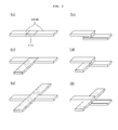
- the protection device has a contact surface with the electrode assembly as large as possible so that the heat generated from the inside of the electrode assembly can be detected with high sensitivity. Therefore, it is preferable that the protection device extends by a predetermined length along the direction away from the longitudinal direction of the lead connected by the protection device, preferably along the perpendicular direction (see, FIGs. 2c, 2d, 2e and 2f ). By doing so, the protection device can extend on the lateral surface of the casing, while minimizing a drop in energy density per volume caused by such extended protection sheet.
- an electrode assembly 1 is enclosed and sealed by a casing 2 made of an insulation material and includes a cathode, anode, separator interposed between the cathode and anode and a gel polymer.
- a cathode lead 3 and anode lead 4 are connected to a cathode and anode, respectively.
- the cathode lead and anode lead are heat sealed into a sealing region 5 disposed in the circumference of the casing.
Abstract
Description
- The present invention relates to an electrochemical device comprising an electrode lead having a protection device for interrupting electric current when the temperature of an electrochemical device increases.
- Recently, there is an increasing interest in energy storage technology. Batteries have been widely used as energy sources in portable phones, camcorders, notebook computers, PCs and electric cars, resulting in intensive research and development into them. In this regard, electrochemical devices are subjects of great interest. Particularly, development of rechargeable secondary batteries is the focus of attention. Recently, research and development into novel electrode and battery that can improve capacity density and specific energy have been made intensively in the field of secondary batteries.
- Among currently used secondary batteries, lithium secondary batteries appearing in early 1990's have drive voltage and energy density higher than those of conventional batteries using aqueous electrolytes (such as Ni-MH batteries, NI-Cd batteries, H2SO4-Pb batteries, etc). For these reasons, lithium secondary batteries are advantageously used. However, such lithium secondary batteries have disadvantages in that organic electrolytes used therein may cause safety-related problems resulting in ignition and explosion of the batteries and that processes for manufacturing such batteries are complicated. More recently, lithium ion polymer batteries developed for the purpose of overcoming the shortcomings of lithium ion batteries have been thought of as a candidate leading the next generation batteries. However, such lithium polymer batteries developed up to date have a relatively low capacity compared to lithium ion batteries and provide insufficient discharge capacity at low temperature. Therefore, there is an imminent need for batteries capable of solving the above-mentioned problems.
- Lithium ion batteries have an operation mechanism different from that of nickel-metal hydride batteries or nickelcadmium batteries. Each of LiCoO2 and graphite used in a lithium ion battery as cathode active material and anode active material, respectively, has a crystal structure in which an empty space is present. During charge/discharge cycles, Li ions repeatedly intercalate into and deintercalate out of the empty space and thus move inside of a battery.
- A battery is manufactured in its discharged state. During a charge cycle, lithium contained in the LiCoO2 crystals deintercalates out of the crystals, moves to an anode and thus intercalates into the crystal structure of graphite. On the contrary, during a discharge cycle, lithium contained in graphite deintercalates out of the crystal structure of graphite and then intercalates into crystals present in a cathode. Such repeated comings and goings of Li ions between a cathode and anode are referred to as the so-called rocking chair concept, which forms the operation mechanism of a lithium ion battery.
- Evaluation of and security in safety of batteries are very important. It should be considered in the first place that users have to be protected from being damaged due to malfunctioning of batteries. To satisfy this, safety of batteries is strictly restricted in terms of ignition and combustion in batteries by safety standards. Overcharge of a battery is the most imminent problem to be solved.
- All batteries are dangerous when overcharged and lithium ion batteries cannot be an exception. When a battery is overcharged, lithium ions move continuously from a cathode to an anode present in a state wherein lithium completely occupies the empty space in the crystal structure of graphite, as viewed from the geometrical point, so that lithium ions grow on the surface of anode, resulting in formation of dendrite having a resinous structure. Such dendrite may result in explosion and firing of a battery when the battery is abused. Morphology of the dendrite depends on the kind of lithium salt contained in an electrolyte.
- The most dangerous phenomenon resulting from overcharge of a battery is "high-temperature overcharge", which is the worst case occurring in lithium ion batteries. When a lithium ion battery is overcharged to a voltage of 4.2V or more, electrolyte starts to be decomposed and tends to have a high possibility for ignition as the battery temperature increases to reach the flash point. However, there is no occurrence of ignition in the closed spaced of a battery because oxygen is not supplied thereto. LiCoO2 used as cathode active material forms a layered structure of "O-Co-O" in which a Co layer locates between oxygen atom layers, such structure forming a sandwich-like shape. Additionally, LiCoO2 may form a crystal structure of "O-Co-O-Li-O-Co-O" in which a Li layer locates between two sandwich-like structures. The latter structure is not stable.
- At high temperature, LiCoO2 has a great tendency to be converted into a stable spinel structure (die-like structure). The spinel has a molecular formula of LiCo2O4 and thus has a small amount of oxygen per unit cell compared to a layered structure. Therefore, in this case, remaining oxygen moves to an electrolyte so that oxygen may be supplied to the electrolyte reaching its flash point, thereby causing explosion of a battery. However, because a battery itself cannot prevent the heat emission as mentioned above, many attempts have been made, for example, to mount a protection circuit on a battery or to apply heat obstruction by using a separator.
- Particularly, it is known that protection devices such as a PTC (positive temperature coefficient) device or thermal fuse are efficient when they are disposed in the vicinity of an electrode as heat emitting source (for example, at the central portion or lateral surface of a battery) by means of resistance welding, in order to promptly detect an increase in battery temperature followed by abnormal operation of the battery. Additionally, such protection devices are frequently disposed at the lateral side portion of a battery so as to increase energy efficiency per volume.
- As the most recent approach, Japanese Laid-Open Patent No.
2003-45492 - Therefore, the present invention has been made in view of the above-mentioned problems. It is an object of the present invention to provide an electrochemical device, which comprises a protection device activated immediately in response to an increase in temperature of the electrochemical device to interrupt electric current so that the electrochemical device can be protected while minimizing a drop in energy density per volume of electrochemical device.
- It is another object of the present invention to provide an electrochemical device pack having one or more of the above electrochemical devices.
- According to an aspect of the present invention, there is provided an electrochemical device comprising an electrode assembly having a cathode, anode and an electrolyte, the electrode assembly being enclosed with a casing having an inner surface and an outer surface, wherein the electrochemical device further comprises a protection device to which either or both of a cathode lead for connecting a cathode with an outer terminal and an anode lead for connecting an anode with an outer terminal are connected electrically, the protection device is disposed at a sealing region between inner surfaces of the casing, and the sealing region of the casing is folded so that the sealing region having the protection device is layered on a lateral surface of the casing.
- The protection device that is disposed at the sealing region of a casing according to the present invention includes a PTC device, thermal fuse, bimetal device, Zener diode, etc.
- According to the present invention, the protection device is electrically connected to an electrode lead in series or in parallel, preferably in series. The connection between the cathode lead or anode lead and the protection device can be made by welding.
- Preferably, the protection device that may be used in the present invention is a protection device that protects an electrochemical device from an increase in temperature of the electrochemical device.
- The PTC device used in the present invention as protection device, which is electrically connected to an electrode lead in series, can interrupt electric current by the occurrence of a rapid increase in resistance, when the temperature of a battery increases abnormally (for example, in the case of an over-current or external short circuit, particularly in the case of an overcharge), so that the temperature cannot increase any more. Therefore, the PTC device can improve the battery safety.
- Particularly, it is preferable to perform taping of both surfaces of the lead by using an insulation film in order to prevent interconnection in the lead to be folded (see,
FIG. 6a ). Additionally, the lead or the protection device is taped with an insulation tape in order to prevent electric short circuit. Particular examples of the insulation film include an imide insulation film. - Further, the portion having the protection device is preferably coated with a polymer in order to prevent the breakage of a protection device (for example, a PTC sheet) caused by infiltration of an electrolyte into the protection device. Nonlimiting examples of the polymer include polyethylene, polypropylene, polyurethane, epoxy resin, silicone, etc.
- According to the invention, the protection device is disposed at the sealing region between inner surfaces of a casing. In this case, it is preferable to minimize the temperature and pressure upon sealing so that the breakage of the protection device itself can be prevented.
- Meanwhile, it is more efficient in terms of safety that the protection device has a contact surface with the electrode assembly as large as possible so that the heat generated from the inside of the electrode assembly can be detected with high sensitivity. Therefore, it is preferable that the protection device extends by a predetermined length along the direction away from the longitudinal direction of the lead connected by the protection device, preferably along the perpendicular direction (see,
FIGs. 2c, 2d, 2e and 2f ). By doing so, the protection device can extend on the lateral surface of the casing, while minimizing a drop in energy density per volume caused by such extended protection sheet. If the protection device is disposed at the sealing region of the casing and the sealing region of the casing is folded to be layered on the lateral surface of the casing, the extended portion of the protection device is also layered on the lateral surface of the casing. Particularly, when the protection device is present in the vicinity of an electrode tab lead, the heat generated from an electrochemical device during an overcharge state is conducted mainly through the electrode lead. As a result, heat conductivity to the protection device may decrease. Therefore, according to the present invention, the portion of the protection device exposed by extending from a linear lead, preferably along the perpendicular direction, can improve the sensitivity to an increase in temperature of the electrochemical device as well as heat conductivity (see,FIGs. 3 ,7 and11 ). In other words, the heat generated from the electrochemical device under an overcharge state can be conducted not only through the electrode lead but also directly to the exposed portion of the protection device, thereby increasing operational efficiency of the protection device. - As shown in
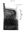
FIG. 13 , when an electrode assembly having a stacked structure is provided and each lead is connected to an electrode tab in the form of "V" (see, drawingnumber 6 inFIG. 1 ), a vacancy is created between the stacked surface of the electrode assembly and the casing (see, drawingnumber 7 inFIG. 1 ) . - Although the present invention can be generally applied to lithium ion batteries, it can also be applied to all electrochemical devices including nickel-metal hydride batteries, nickel cadmium batteries, etc. Additionally, the present invention will have applicability to future batteries that can substitute for lithium ion batteries.
- An embodiment of the present invention, characterized by comprising a protection device disposed at the sealing region of a casing, is suitable for pouch-type batteries. Contrary to prismatic or cylindrical batteries, pouch-type batteries generally using an aluminum pouch as casing permit the protection device to be disposed at the sealing region in practice.
- Hereinafter, preferred embodiments of pouch-type batteries, particularly lithium ion polymer secondary batteries, to which the present invention is applied, will be explained in more detail with reference to the accompanying drawings.
- As shown in
FIG. 1 , anelectrode assembly 1 is enclosed and sealed by acasing 2 made of an insulation material and includes a cathode, anode, separator interposed between the cathode and anode and a gel polymer. Acathode lead 3 andanode lead 4 are connected to a cathode and anode, respectively. The cathode lead and anode lead are heat sealed into a sealingregion 5 disposed in the circumference of the casing. -
FIG. 2 shows several embodiments of two leads connected to each other by a protection device (for example, PTC device) according to the present invention. - The PTC device is formed by crosslinking between carbon black as conductive agent and polyethylene as matrix polymer.
- Hereinafter, the present invention will be exemplified by a lithium secondary battery.
- The lithium secondary battery includes a cathode comprising a lithium composite oxide as cathode active material, an anode capable of lithium intercalation/deintercalation, a nonaqueous electrolyte and a separator.
- The cathode active material forming the cathode includes a lithium composite oxide. Particular examples of the lithium composite oxide include lithium intercalation material-based oxides such as lithiated manganese oxides, lithiated cobalt oxides, lithiated nickel oxides or other composite oxides obtained by combination thereof. The cathode active material is bonded to a cathode current collector such as foil formed of aluminum, nickel or combinations thereof to provide the cathode.
- The anode active material forming the anode of a lithium secondary battery includes lithium metal, lithium alloys, or lithium intercalation materials such as carbon, petroleum coke, activated carbon, graphite or other types of carbon. The anode active material is bonded to an anode current collector such as foil formed of copper, gold, nickel, copper alloys or combinations thereof to provide the anode.
- The separator that may be used has a micro-porous structure and includes multilayer films formed of polyethylene, polypropylene or combinations thereof, or polymer films for solid polymer electrolytes or gel polymer electrolytes such as polyvinylidene fluoride, polyethylene oxide, polyacrylonitrile or polyvinylidene fluoride-hexafluoropropylene copolymer.
- The electrolyte that may be used in the present invention includes a salt represented by the formula of A+B- , wherein A+ represents an alkali metal cation selected from the group consisting of Li+, Na+, K+ and combinations thereof, and B- represents an anion selected from the group consisting of PF6, BF4 - ' Cl-, Br- , I- , ClO4 - , ASF6 -, CH3CO2 - , CF3SO3 - , N (CF3SO2)2 - , C (CF2S02)3 - and combinations thereof, the salt being dissolved or dissociated in an organic solvent selected from the group consisting of propylene carbonate (PC), ethylene carbonate (EC), diethyl carbonate (DEC), dimethyl carbonate (DMC), dipropyl carbonate (DPC), dimethyl sulfoxide, acetonitrile, dimethoxyethane, diethoxyethane, tetrahydrofuran, N-methyl-2-pyrrolidone (NMP), ethylmethyl carbonate (EMC), gamma-butyrolactone and mixtures thereof.
- Additionally, there is no particular limitation in shape of the electrochemical device to which the present invention is applied. The electrochemical device may be a thin-type or large-size device, etc. Further, the present invention may be applied to a stacked device having a plurality of electrochemical devices, hard pack-type device having a pack casing in which an electrochemical device is contained and a soft pack-type device including an electrochemical device exposed to the exterior.
-
-
FIG. 1 is a schematic view showing a pouch-shaped electrochemical device used in the present invention. -
FIGs. 2a-2f are illustrative views each showing two leads connected to each other via a protection device (e.g. PTC) according to the present invention. -
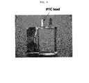
FIG. 3 is a picture showing an embodiment of a T-shaped PTC lead for practical use. -
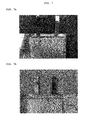
FIGs. 4-7 are pictures each showing an embodiment of a PTC lead applied to a battery for practical use, whereinFIG. 4 shows a PTC lead whose PTC portion is present on the exterior of a casing;FIG. 5 shows a PTC lead whose PTC portion is present at the adhesion region (sealing region) of a casing;FIG. 6a shows a PTC lead whose PTC portion is disposed in the vicinity of an electrode tab inside of a casing;FIG. 6b shows the appearance of a battery packed with a casing after mounting a PTC in the Vicinity of an electrode tab inside of the casing as shown inFIG. 6a ;FIG. 7a shows a T-shaped PTC lead whose PTC portion is disposed in an inner space (a space between a cathode tab and anode tab) created by the formation of a V-form in a battery having a stack-and-winding structure; andFIG. 7b shows the appearance of a battery packed with a casing, the battery including the PTC lead disposed as shown inFIG. 7a . -
FIG. 8 is a graph showing variations in temperature and voltage, obtained from the overcharge test of an actual polymer battery (Comparative Example 1) having a PTC lead whose PTC portion is disposed on the exterior of a casing. -
FIG. 9 is a graph showing overcharge behaviors of a battery (Example 1) having a PTC lead whose PTC portion is disposed at the sealing region. -
FIG. 10 is a graph showing overcharge behaviors of a battery (Example 2) having a PTC lead whose PTC portion is disposed at a tab region inside of the battery. -
FIG. 11 is a graph showing overcharge behaviors of a battery (Example 3) having a PTC lead whose PTC portion extends in the space between a cathode tab and anode tab. -
FIG. 12 is a graph showing overcharge behaviors of a battery (Comparative Example 2) having a conventional lead instead of a PTC lead. -
FIG. 13 is a perspective view showing the formation of a V-form in a battery having a stacked structure, when viewed from a lateral side. -
- 1: an electrode assembly
- 2: a casing (aluminum pouch-type)
- 3: a cathode lead
- 4: an anode lead
- 5: an adhesion region (sealing region) of a casing
- 6: a V-form of electrode tab lead
- 7: a space between a cathode tab and anode tab created by the formation of a V-form
- Reference will now be made in detail to the preferred embodiments of the present invention. It is to be understood that the following examples are illustrative only and the present invention is not limited thereto.
- A PTC device (Model No. NSP-L500) available from LG Cable Co. was mounted on a lithium ion polymer secondary battery (Trade Name: ICP323456, 600 mAh) available from LG Chem., Ltd. The PTC device was heat sealed with a cathode lead to provide the form as shown in
FIG. 2b . Then, the battery was enclosed with a pouch-type casing in such a manner that the PTC portion is present on the exterior of the casing as shown inFIG. 4 . - The same lithium ion polymer secondary battery available from LG Chem., Ltd. and the same PTC device available from LG Cable Co. as Comparative Example 1 were used. In this Example, the PTC device was heat sealed with a cathode lead to provide the form as shown in
FIG. 2b . Then, the battery was enclosed with a pouch-type casing in such a manner that the PTC portion is present at the inner sealing region of the casing as shown inFIG. 5 . - The same lithium ion polymer secondary battery available from LG Chem., Ltd. and the same PTC device available from LG Cable Co. as Comparative Example 1 were used. Similarly, the PTC device was heat sealed with a cathode lead to provide the form as shown in
FIG. 2b . Then, the battery was enclosed with a pouch-type casing in such a manner that the PTC portion is present inside of the casing as shown inFIG. 6a . Particularly, in order to minimize the loss of energy density, the lead was folded so that the PTC sheet is disposed between the stacked surface (surface having the lead) of the electrode assembly and the casing. Additionally, the lead was insulated by using an imide film so as to prevent interconnection between leads (see,FIG. 6a ) . - The same lithium ion polymer secondary battery available from LG Chem., Ltd. and the same PTC device available from LG Cable Co. as Comparative Example 1 were used. Similarly, the PTC device was heat sealed with a cathode lead to provide the form as shown in
FIG. 2d . Then, the battery was enclosed with a pouch-type casing in such a manner that the extended portion of the PTC sheet is present between the cathode tab and anode tab. Additionally, the PTC sheet was coated with a polymer so as to prevent breakage of the PTC layer caused by infiltration of electrolyte. - The same battery as Comparative Example 1 was provided, the battery using a conventional lead with no protection device.
- Each of the lithium ion polymer secondary batteries obtained from the above Examples 1, 2 and 3 and Comparative Examples 1 and 2 was overcharged (20V/3C) and variations in temperature and voltage were shown in
FIG. 8 (Comparative Example 1) ,FIG. 9 (Example 1) ,FIG. 10 (Example 2),FIG. 11 (Example 3) andFIG. 12 (Comparative Example 2). As can be seen fromFIGs. 8 and12 , both of the battery using no PTC device and the battery including a PTC device disposed on the exterior of the battery casing exploded, while the batteries including a PTC layer disposed inside of the batteries were safe as shown inFIGs. 9 ,10 and 11 . Referring toFIGs. 8 and12 , each battery ignited and the battery temperature increased to 200°C or higher. However, as can be seen fromFIGs. 9 ,10 and 11 , the highest temperature was 105°C, 45°C and 35°C in each case (based on the surface temperature of an electrode assembly). Additionally, it can be seen that the battery according to Example 3, which includes a sheet-like PTC protection device extending from the lead so as to provide a large contact area with the electrode assembly, was safer than the battery according to Example 2, which has a relatively small contact area. - As can be seen from the above results obtained from the overcharge test, disposing a PTC device inside of an electrochemical device provides a significant improvement in terms of safety, compared to disposing a PTC device on the exterior of the electrochemical device. It is thought that this results from the temperature dependency of a PTC device, which is the principle of operation in PTC devices, the temperature dependency being more sensitive inside of an electrochemical device. Therefore, PTC leads having the form of
FIG. 5 ,6 or7 are the most preferred embodiments in terms of safety and performance. - The PTC lead as described above provided excellent results after various safety tests including nail penetration test, high-temperature oven test, etc., for a pack comprising a plurality of electrochemical devices as well as in the above overcharge test.
- As can be seen from the foregoing, the electrochemical device according to the present invention includes a protection device disposed at the sealing region of a casing or inside of a casing, wherein the largest surface of the protection device is layered on the lateral surface of the casing. Therefore, it is possible to improve the sensitivity of the protection device to an increase in temperature of the battery, reaction degree and heat conductivity, while minimizing a drop in energy density per volume caused by the protection device. Ultimately, according to the present invention, it is possible to improve the safety of an electrochemical device.
Claims (10)
- An electrochemical device comprising an electrode assembly having a cathode, anode and an electrolyte, the electrode assembly being enclosed with a casing having an inner surface and an outer surface, wherein the electrochemical device further comprises a protection device to which either or both of a cathode lead for connecting a cathode with an outer terminal and an anode lead for connecting an anode with an outer terminal are connected electrically, the protection device is disposed at a sealing region between inner surfaces of the casing, and the sealing region of the casing is folded so that the sealing region having the protection device is layered on a lateral surface of the casing.
- The electrochemical device according to claim 1, wherein the protection device is one interrupting electric current when temperature of the electrochemical device increases.
- The electrochemical device according to claim 1, wherein the protection device is selected from the group consisting of a PTC device, thermal fuse, bimetal device and Zener diode.
- The electrochemical device according to claim 1, wherein the lead or the protection device is taped with an insulation film in order to prevent short circuit.
- The electrochemical device according to claim 1, wherein the protection device is coated with a polymer capable of inhibiting infiltration of electrolyte.
- The electrochemical device according to claim 1, wherein the protection device has a portion extending along a direction away from the longitudinal direction of the lead connected by the protection device.
- The electrochemical device according to claim 6, wherein the protection device has a portion extending along a direction perpendicular to the longitudinal direction of the lead connected by the protection device.
- The electrochemical device according to claim 1, wherein the cathode lead or anode lead is connected with the protection device by welding.
- An electrochemical device pack, which includes one electrochemical device or a plurality of electrochemical devices as claimed in claim 1.
- The electrochemical device as claimed in claim 9, wherein the electrochemical devices are connected in series or in parallel.
Applications Claiming Priority (2)
| Application Number | Priority Date | Filing Date | Title |
|---|---|---|---|
| KR20040025394 | 2004-04-13 | ||
| EP05764933A EP1756891B1 (en) | 2004-04-13 | 2005-04-12 | Electrochemical device comprising electrode lead having protection device |
Related Parent Applications (1)
| Application Number | Title | Priority Date | Filing Date |
|---|---|---|---|
| EP05764933.7 Division | 2005-04-12 |
Publications (3)
| Publication Number | Publication Date |
|---|---|
| EP2416401A2 true EP2416401A2 (en) | 2012-02-08 |
| EP2416401A3 EP2416401A3 (en) | 2012-03-28 |
| EP2416401B1 EP2416401B1 (en) | 2013-05-08 |
Family
ID=35150269
Family Applications (2)
| Application Number | Title | Priority Date | Filing Date |
|---|---|---|---|
| EP20110184847 Active EP2416401B1 (en) | 2004-04-13 | 2005-04-12 | Electrochemical device comprising electrode lead having protection device |
| EP05764933A Active EP1756891B1 (en) | 2004-04-13 | 2005-04-12 | Electrochemical device comprising electrode lead having protection device |
Family Applications After (1)
| Application Number | Title | Priority Date | Filing Date |
|---|---|---|---|
| EP05764933A Active EP1756891B1 (en) | 2004-04-13 | 2005-04-12 | Electrochemical device comprising electrode lead having protection device |
Country Status (10)
| Country | Link |
|---|---|
| US (1) | US7618724B2 (en) |
| EP (2) | EP2416401B1 (en) |
| JP (1) | JP4802188B2 (en) |
| KR (1) | KR100678835B1 (en) |
| CN (1) | CN100541867C (en) |
| BR (1) | BRPI0508427B8 (en) |
| CA (1) | CA2562960C (en) |
| RU (1) | RU2326467C1 (en) |
| TW (1) | TWI262615B (en) |
| WO (1) | WO2005101547A1 (en) |
Cited By (1)
| Publication number | Priority date | Publication date | Assignee | Title |
|---|---|---|---|---|
| EP2760061A1 (en) * | 2013-01-29 | 2014-07-30 | Samsung SDI Co., Ltd. | Battery cell with a protection element |
Families Citing this family (40)
| Publication number | Priority date | Publication date | Assignee | Title |
|---|---|---|---|---|
| US8883354B2 (en) | 2006-02-15 | 2014-11-11 | Optodot Corporation | Separators for electrochemical cells |
| KR100906253B1 (en) * | 2006-05-01 | 2009-07-07 | 주식회사 엘지화학 | Secondary Battery Having Electrode With Self Cutting Part To Be Destructed On Application Of Over-Current |
| WO2008016243A1 (en) * | 2006-07-31 | 2008-02-07 | Lg Chem, Ltd. | Secondary battery with top sealed portion of improved structure |
| DE102007033427A1 (en) * | 2007-07-18 | 2009-01-22 | Robert Bosch Gmbh | Arrangement with a housing |
| DE102008020912A1 (en) * | 2008-04-17 | 2009-10-22 | Varta Microbattery Gmbh | Galvanic cell with irreversible fuse |
| US8530084B2 (en) * | 2008-06-25 | 2013-09-10 | Panasonic Corporation | Electrode structure for non-aqueous electrolyte secondary battery, method for producing the same, and non-aqueous electrolyte secondary battery |
| KR20170045366A (en) | 2009-05-26 | 2017-04-26 | 옵토도트 코포레이션 | Batteries utilizing anode coating directly on nanoporous separators |
| JP5474466B2 (en) * | 2009-09-18 | 2014-04-16 | 三洋電機株式会社 | Stacked battery |
| JP5658450B2 (en) | 2009-11-12 | 2015-01-28 | 川崎重工業株式会社 | Battery system |
| JP5577802B2 (en) * | 2010-04-07 | 2014-08-27 | 日産自動車株式会社 | Battery module |
| KR20130112704A (en) * | 2010-05-06 | 2013-10-14 | 타이코 일렉트로닉스 저팬 지.케이. | Ptc device and secondary battery equipped with same |
| EP2590179B1 (en) * | 2010-07-02 | 2017-10-11 | Littelfuse Japan G.K. | Ptc device and secondary battery having same |
| CN101887960B (en) * | 2010-07-13 | 2015-07-29 | 清华大学 | Lithium ion cell polar ear and there is the lithium ion battery of this lug |
| PL2596538T3 (en) | 2010-07-19 | 2019-06-28 | Optodot Corporation | Separators for electrochemical cells |
| JP2012028089A (en) * | 2010-07-21 | 2012-02-09 | Sanyo Electric Co Ltd | Nonaqueous secondary battery and nonaqueous secondary battery pack |
| CN103081176B (en) * | 2010-07-22 | 2016-04-20 | 加拿大巴斯姆有限公司 | The afflux terminal of electrochemical cell |
| EP2426759B1 (en) * | 2010-09-01 | 2014-12-31 | FDK Twicell Co., Ltd. | Battery |
| KR101655275B1 (en) * | 2010-12-13 | 2016-09-08 | 주식회사 엘지화학 | Secondary battery including layered welding zone having PTC-characteristics and Manufacturing method thereof |
| KR101213482B1 (en) * | 2010-12-14 | 2012-12-20 | 삼성에스디아이 주식회사 | Secondary battery |
| KR101641621B1 (en) * | 2010-12-14 | 2016-07-22 | 주식회사 엘지화학 | Secondary electric cell and battery pack with enhanced safety |
| JP5704645B2 (en) * | 2011-03-30 | 2015-04-22 | Necエナジーデバイス株式会社 | Secondary battery |
| KR101320392B1 (en) * | 2011-09-02 | 2013-10-23 | 삼성에스디아이 주식회사 | A lithium polymer battery |
| US9005786B2 (en) | 2011-10-21 | 2015-04-14 | GM Global Technology Operations LLC | Integrated cell voltage sense line fusing |
| US9343716B2 (en) * | 2011-12-29 | 2016-05-17 | Apple Inc. | Flexible battery pack |
| RU2554110C2 (en) * | 2011-12-29 | 2015-06-27 | Федеральное государственное военное образовательное учреждение высшего профессионального образования "Военный учебно-научный центр Сухопутных войск Общевойсковая академия Вооруженных Сил Российской Федерации" | Method of conversion of ionised medium energy into electric energy |
| KR101302077B1 (en) * | 2012-12-17 | 2013-09-05 | 주식회사 엘지화학 | Secondary battery including fuse-inserted electrode lead |
| KR102236436B1 (en) | 2013-04-29 | 2021-04-06 | 옵토도트 코포레이션 | Nanoporous composite separators with increased thermal conductivity |
| CN103956532A (en) * | 2014-05-12 | 2014-07-30 | 东莞新能德科技有限公司 | Polymer lithium-ion battery |
| EP3232496A4 (en) * | 2014-12-08 | 2018-06-27 | Littelfuse Japan G.K. | Electrode |
| US10381623B2 (en) | 2015-07-09 | 2019-08-13 | Optodot Corporation | Nanoporous separators for batteries and related manufacturing methods |
| US10439196B2 (en) | 2015-12-18 | 2019-10-08 | Bourns, Inc. | Electromechanical circuit breaker |
| US10637017B2 (en) | 2016-09-23 | 2020-04-28 | Apple Inc. | Flexible battery structure |
| JP6669122B2 (en) * | 2017-04-07 | 2020-03-18 | トヨタ自動車株式会社 | Stacked battery |
| CN109920962A (en) * | 2017-12-13 | 2019-06-21 | 比亚迪股份有限公司 | Battery system and electric car |
| KR102380951B1 (en) | 2018-06-22 | 2022-03-31 | 보우린스, 인크. | circuit breaker |
| CN109265157B (en) * | 2018-10-29 | 2022-01-21 | 惠州嘉科实业有限公司 | Low-resistance NTC thermistor with V-shaped pin and preparation method thereof |
| CN114600311A (en) | 2019-08-27 | 2022-06-07 | 伯恩斯公司 | Connector with integrated thermal cut-off device for battery pack |
| KR20210124763A (en) * | 2020-04-07 | 2021-10-15 | 주식회사 엘지에너지솔루션 | Electrode Lead Having Dissimilar Metals and Manufacturing Method Thereof |
| CN111509181A (en) * | 2020-04-20 | 2020-08-07 | 海口博澳国兴新能源科技有限公司 | Battery tab and preparation method thereof |
| CN112968256A (en) * | 2021-02-03 | 2021-06-15 | 东莞新能安科技有限公司 | Electrochemical device and electronic device |
Citations (1)
| Publication number | Priority date | Publication date | Assignee | Title |
|---|---|---|---|---|
| JP2003045492A (en) | 2001-07-31 | 2003-02-14 | Sony Corp | Battery and battery pack |
Family Cites Families (24)
| Publication number | Priority date | Publication date | Assignee | Title |
|---|---|---|---|---|
| JPS5717560A (en) | 1980-07-08 | 1982-01-29 | Citizen Watch Co Ltd | Protective case for battery with lead plate |
| JPH0512929Y2 (en) * | 1987-09-02 | 1993-04-05 | ||
| JPH0834098B2 (en) * | 1989-02-07 | 1996-03-29 | 日立マクセル株式会社 | Cylindrical organic electrolyte battery with PTC element |
| JPH08153509A (en) | 1994-11-28 | 1996-06-11 | Shin Kobe Electric Mach Co Ltd | Sealed lead-acid battery having temperature protection unit |
| US5750277A (en) | 1996-04-10 | 1998-05-12 | Texas Instruments Incorporated | Current interrupter for electrochemical cells |
| JPH1167188A (en) * | 1997-08-22 | 1999-03-09 | Japan Storage Battery Co Ltd | Lead terminal for secondary battery and lithium secondary battery |
| JP3905973B2 (en) * | 1998-03-10 | 2007-04-18 | 三洋電機株式会社 | Thin battery |
| JP3221870B2 (en) | 2000-01-07 | 2001-10-22 | 松下電器産業株式会社 | Secondary battery with battery protection circuit |
| KR100342045B1 (en) * | 1999-04-16 | 2002-06-27 | 김순택 | Secondary battery |
| WO2000070702A1 (en) * | 1999-05-17 | 2000-11-23 | Matsushita Electric Industrial Co., Ltd. | Circuit and device for protecting secondary battery |
| EP1071147A1 (en) * | 1999-07-19 | 2001-01-24 | Toshiba Battery Co., Ltd. | Battery pack |
| JP2002298830A (en) * | 2001-03-30 | 2002-10-11 | Tdk Corp | Secondary battery |
| JP2002358947A (en) * | 2001-06-01 | 2002-12-13 | Tdk Corp | Electrochemical device |
| JP4264203B2 (en) | 2001-06-01 | 2009-05-13 | ハマダ印刷機械株式会社 | Printing plate retainer |
| JP4984366B2 (en) | 2001-09-27 | 2012-07-25 | ソニー株式会社 | BATTERY STORAGE PACK, CONNECTION BODY HAVING BATTERY PROTECTION ELEMENT USED FOR THE SAME, AND METHOD FOR PRODUCING BATTERY STORAGE PACK |
| JP2004011186A (en) | 2002-06-04 | 2004-01-15 | Seiji Yoneima | Building interior and exterior panel with high weather resistance |
| KR20040017094A (en) * | 2002-08-20 | 2004-02-26 | 삼성에스디아이 주식회사 | Pouch type secondary battery with safty vent |
| JP4218792B2 (en) * | 2002-09-18 | 2009-02-04 | マクセル北陸精器株式会社 | Non-aqueous secondary battery |
| DE10250857A1 (en) | 2002-10-25 | 2004-05-13 | Varta Microbattery Gmbh | Rechargeable galvanic element with at least one lithium intercalating electrode |
| JP3789438B2 (en) * | 2003-03-03 | 2006-06-21 | Necラミリオンエナジー株式会社 | Film outer battery |
| KR100496305B1 (en) * | 2003-05-22 | 2005-06-17 | 삼성에스디아이 주식회사 | Pouched-type lithium secondary battery and the fabrication method thereof |
| KR100544119B1 (en) * | 2003-06-24 | 2006-01-23 | 삼성에스디아이 주식회사 | Pouched-type lithium secondary battery |
| JP4923379B2 (en) * | 2003-10-27 | 2012-04-25 | ソニー株式会社 | Secondary battery and battery pack |
| EP1716606B1 (en) * | 2004-01-30 | 2011-04-20 | LG Chem, Ltd. | Battery having specific package structure |
-
2005
- 2005-04-12 EP EP20110184847 patent/EP2416401B1/en active Active
- 2005-04-12 WO PCT/KR2005/001059 patent/WO2005101547A1/en active Application Filing
- 2005-04-12 CA CA2562960A patent/CA2562960C/en active Active
- 2005-04-12 BR BRPI0508427A patent/BRPI0508427B8/en active IP Right Grant
- 2005-04-12 EP EP05764933A patent/EP1756891B1/en active Active
- 2005-04-12 US US11/103,732 patent/US7618724B2/en active Active
- 2005-04-12 KR KR1020050030349A patent/KR100678835B1/en active IP Right Grant
- 2005-04-12 CN CNB2005800110829A patent/CN100541867C/en active Active
- 2005-04-12 RU RU2006139941A patent/RU2326467C1/en active
- 2005-04-12 JP JP2007508273A patent/JP4802188B2/en active Active
- 2005-04-13 TW TW94111741A patent/TWI262615B/en active
Patent Citations (1)
| Publication number | Priority date | Publication date | Assignee | Title |
|---|---|---|---|---|
| JP2003045492A (en) | 2001-07-31 | 2003-02-14 | Sony Corp | Battery and battery pack |
Cited By (2)
| Publication number | Priority date | Publication date | Assignee | Title |
|---|---|---|---|---|
| EP2760061A1 (en) * | 2013-01-29 | 2014-07-30 | Samsung SDI Co., Ltd. | Battery cell with a protection element |
| CN103972431A (en) * | 2013-01-29 | 2014-08-06 | 三星Sdi株式会社 | Battery cell |
Also Published As
| Publication number | Publication date |
|---|---|
| RU2326467C1 (en) | 2008-06-10 |
| CN1957488A (en) | 2007-05-02 |
| EP1756891B1 (en) | 2012-06-13 |
| US7618724B2 (en) | 2009-11-17 |
| EP1756891A1 (en) | 2007-02-28 |
| BRPI0508427B1 (en) | 2018-02-14 |
| EP1756891A4 (en) | 2010-03-03 |
| JP2007533099A (en) | 2007-11-15 |
| TW200541130A (en) | 2005-12-16 |
| US20060008698A1 (en) | 2006-01-12 |
| EP2416401A3 (en) | 2012-03-28 |
| KR100678835B1 (en) | 2007-02-05 |
| KR20060045625A (en) | 2006-05-17 |
| BRPI0508427A (en) | 2007-07-24 |
| CA2562960A1 (en) | 2005-10-27 |
| TWI262615B (en) | 2006-09-21 |
| BRPI0508427B8 (en) | 2023-01-10 |
| CN100541867C (en) | 2009-09-16 |
| JP4802188B2 (en) | 2011-10-26 |
| EP2416401B1 (en) | 2013-05-08 |
| WO2005101547A1 (en) | 2005-10-27 |
| CA2562960C (en) | 2010-10-19 |
Similar Documents
| Publication | Publication Date | Title |
|---|---|---|
| EP2416401B1 (en) | Electrochemical device comprising electrode lead having protection device | |
| EP2219247B1 (en) | Cylindrical secondary battery | |
| US8048551B2 (en) | Battery safety device and battery having the same | |
| KR20110042119A (en) | Battery module and battery pack using the same | |
| US20060093897A1 (en) | Pouch type lithium rechargeable battery | |
| JP2012049135A (en) | Secondary battery with improved safety | |
| JP2009099320A (en) | Battery pack and its manufacturing method | |
| KR101999529B1 (en) | Pouch-Type Secondary Battery Having Electrode Lead with Couple Notch | |
| JP5119665B2 (en) | Battery pack | |
| KR101786991B1 (en) | Secondary battery module | |
| KR101520148B1 (en) | Secondary battery comprising apparatus for preventing overcharge | |
| KR20060044412A (en) | Safety element for battery and battery with the same | |
| KR101416851B1 (en) | Secondary Battery | |
| WO2021199484A1 (en) | Secondary battery | |
| KR101311493B1 (en) | Lithium secondary battery | |
| JPH11102682A (en) | Thin secondary battery | |
| KR20060004441A (en) | Safety element and secondary battery with the same | |
| JP2004288397A (en) | Current breaking element and secondary battery using it |
Legal Events
| Date | Code | Title | Description |
|---|---|---|---|
| 17P | Request for examination filed |
Effective date: 20111012 |
|
| AC | Divisional application: reference to earlier application |
Ref document number: 1756891 Country of ref document: EP Kind code of ref document: P |
|
| AK | Designated contracting states |
Kind code of ref document: A2 Designated state(s): AT BE BG CH CY CZ DE DK EE ES FI FR GB GR HU IE IS IT LI LT LU MC NL PL PT RO SE SI SK TR |
|
| PUAI | Public reference made under article 153(3) epc to a published international application that has entered the european phase |
Free format text: ORIGINAL CODE: 0009012 |
|
| PUAL | Search report despatched |
Free format text: ORIGINAL CODE: 0009013 |
|
| AK | Designated contracting states |
Kind code of ref document: A3 Designated state(s): AT BE BG CH CY CZ DE DK EE ES FI FR GB GR HU IE IS IT LI LT LU MC NL PL PT RO SE SI SK TR |
|
| RIC1 | Information provided on ipc code assigned before grant |
Ipc: H01M 2/02 20060101AFI20120220BHEP |
|
| GRAP | Despatch of communication of intention to grant a patent |
Free format text: ORIGINAL CODE: EPIDOSNIGR1 |
|
| GRAS | Grant fee paid |
Free format text: ORIGINAL CODE: EPIDOSNIGR3 |
|
| GRAA | (expected) grant |
Free format text: ORIGINAL CODE: 0009210 |
|
| AC | Divisional application: reference to earlier application |
Ref document number: 1756891 Country of ref document: EP Kind code of ref document: P |
|
| AK | Designated contracting states |
Kind code of ref document: B1 Designated state(s): AT BE BG CH CY CZ DE DK EE ES FI FR GB GR HU IE IS IT LI LT LU MC NL PL PT RO SE SI SK TR |
|
| REG | Reference to a national code |
Ref country code: GB Ref legal event code: FG4D |
|
| REG | Reference to a national code |
Ref country code: CH Ref legal event code: EP Ref country code: AT Ref legal event code: REF Ref document number: 611459 Country of ref document: AT Kind code of ref document: T Effective date: 20130515 |
|
| REG | Reference to a national code |
Ref country code: IE Ref legal event code: FG4D |
|
| REG | Reference to a national code |
Ref country code: DE Ref legal event code: R096 Ref document number: 602005039543 Country of ref document: DE Effective date: 20130704 |
|
| REG | Reference to a national code |
Ref country code: AT Ref legal event code: MK05 Ref document number: 611459 Country of ref document: AT Kind code of ref document: T Effective date: 20130508 |
|
| REG | Reference to a national code |
Ref country code: LT Ref legal event code: MG4D |
|
| REG | Reference to a national code |
Ref country code: NL Ref legal event code: VDEP Effective date: 20130508 |
|
| PG25 | Lapsed in a contracting state [announced via postgrant information from national office to epo] |
Ref country code: FI Free format text: LAPSE BECAUSE OF FAILURE TO SUBMIT A TRANSLATION OF THE DESCRIPTION OR TO PAY THE FEE WITHIN THE PRESCRIBED TIME-LIMIT Effective date: 20130508 Ref country code: AT Free format text: LAPSE BECAUSE OF FAILURE TO SUBMIT A TRANSLATION OF THE DESCRIPTION OR TO PAY THE FEE WITHIN THE PRESCRIBED TIME-LIMIT Effective date: 20130508 Ref country code: GR Free format text: LAPSE BECAUSE OF FAILURE TO SUBMIT A TRANSLATION OF THE DESCRIPTION OR TO PAY THE FEE WITHIN THE PRESCRIBED TIME-LIMIT Effective date: 20130809 Ref country code: SI Free format text: LAPSE BECAUSE OF FAILURE TO SUBMIT A TRANSLATION OF THE DESCRIPTION OR TO PAY THE FEE WITHIN THE PRESCRIBED TIME-LIMIT Effective date: 20130508 Ref country code: PT Free format text: LAPSE BECAUSE OF FAILURE TO SUBMIT A TRANSLATION OF THE DESCRIPTION OR TO PAY THE FEE WITHIN THE PRESCRIBED TIME-LIMIT Effective date: 20130909 Ref country code: IS Free format text: LAPSE BECAUSE OF FAILURE TO SUBMIT A TRANSLATION OF THE DESCRIPTION OR TO PAY THE FEE WITHIN THE PRESCRIBED TIME-LIMIT Effective date: 20130908 Ref country code: SE Free format text: LAPSE BECAUSE OF FAILURE TO SUBMIT A TRANSLATION OF THE DESCRIPTION OR TO PAY THE FEE WITHIN THE PRESCRIBED TIME-LIMIT Effective date: 20130508 Ref country code: LT Free format text: LAPSE BECAUSE OF FAILURE TO SUBMIT A TRANSLATION OF THE DESCRIPTION OR TO PAY THE FEE WITHIN THE PRESCRIBED TIME-LIMIT Effective date: 20130508 Ref country code: ES Free format text: LAPSE BECAUSE OF FAILURE TO SUBMIT A TRANSLATION OF THE DESCRIPTION OR TO PAY THE FEE WITHIN THE PRESCRIBED TIME-LIMIT Effective date: 20130819 |
|
| PG25 | Lapsed in a contracting state [announced via postgrant information from national office to epo] |
Ref country code: BG Free format text: LAPSE BECAUSE OF FAILURE TO SUBMIT A TRANSLATION OF THE DESCRIPTION OR TO PAY THE FEE WITHIN THE PRESCRIBED TIME-LIMIT Effective date: 20130808 Ref country code: CY Free format text: LAPSE BECAUSE OF FAILURE TO SUBMIT A TRANSLATION OF THE DESCRIPTION OR TO PAY THE FEE WITHIN THE PRESCRIBED TIME-LIMIT Effective date: 20130508 Ref country code: PL Free format text: LAPSE BECAUSE OF FAILURE TO SUBMIT A TRANSLATION OF THE DESCRIPTION OR TO PAY THE FEE WITHIN THE PRESCRIBED TIME-LIMIT Effective date: 20130508 |
|
| PG25 | Lapsed in a contracting state [announced via postgrant information from national office to epo] |
Ref country code: CZ Free format text: LAPSE BECAUSE OF FAILURE TO SUBMIT A TRANSLATION OF THE DESCRIPTION OR TO PAY THE FEE WITHIN THE PRESCRIBED TIME-LIMIT Effective date: 20130508 Ref country code: DK Free format text: LAPSE BECAUSE OF FAILURE TO SUBMIT A TRANSLATION OF THE DESCRIPTION OR TO PAY THE FEE WITHIN THE PRESCRIBED TIME-LIMIT Effective date: 20130508 Ref country code: SK Free format text: LAPSE BECAUSE OF FAILURE TO SUBMIT A TRANSLATION OF THE DESCRIPTION OR TO PAY THE FEE WITHIN THE PRESCRIBED TIME-LIMIT Effective date: 20130508 Ref country code: EE Free format text: LAPSE BECAUSE OF FAILURE TO SUBMIT A TRANSLATION OF THE DESCRIPTION OR TO PAY THE FEE WITHIN THE PRESCRIBED TIME-LIMIT Effective date: 20130508 Ref country code: BE Free format text: LAPSE BECAUSE OF FAILURE TO SUBMIT A TRANSLATION OF THE DESCRIPTION OR TO PAY THE FEE WITHIN THE PRESCRIBED TIME-LIMIT Effective date: 20130508 |
|
| PG25 | Lapsed in a contracting state [announced via postgrant information from national office to epo] |
Ref country code: NL Free format text: LAPSE BECAUSE OF FAILURE TO SUBMIT A TRANSLATION OF THE DESCRIPTION OR TO PAY THE FEE WITHIN THE PRESCRIBED TIME-LIMIT Effective date: 20130508 Ref country code: IT Free format text: LAPSE BECAUSE OF FAILURE TO SUBMIT A TRANSLATION OF THE DESCRIPTION OR TO PAY THE FEE WITHIN THE PRESCRIBED TIME-LIMIT Effective date: 20130508 Ref country code: RO Free format text: LAPSE BECAUSE OF FAILURE TO SUBMIT A TRANSLATION OF THE DESCRIPTION OR TO PAY THE FEE WITHIN THE PRESCRIBED TIME-LIMIT Effective date: 20130508 |
|
| PLBE | No opposition filed within time limit |
Free format text: ORIGINAL CODE: 0009261 |
|
| STAA | Information on the status of an ep patent application or granted ep patent |
Free format text: STATUS: NO OPPOSITION FILED WITHIN TIME LIMIT |
|
| 26N | No opposition filed |
Effective date: 20140211 |
|
| REG | Reference to a national code |
Ref country code: DE Ref legal event code: R097 Ref document number: 602005039543 Country of ref document: DE Effective date: 20140211 |
|
| PG25 | Lapsed in a contracting state [announced via postgrant information from national office to epo] |
Ref country code: LU Free format text: LAPSE BECAUSE OF FAILURE TO SUBMIT A TRANSLATION OF THE DESCRIPTION OR TO PAY THE FEE WITHIN THE PRESCRIBED TIME-LIMIT Effective date: 20140412 Ref country code: MC Free format text: LAPSE BECAUSE OF FAILURE TO SUBMIT A TRANSLATION OF THE DESCRIPTION OR TO PAY THE FEE WITHIN THE PRESCRIBED TIME-LIMIT Effective date: 20130508 |
|
| REG | Reference to a national code |
Ref country code: CH Ref legal event code: PL |
|
| REG | Reference to a national code |
Ref country code: IE Ref legal event code: MM4A |
|
| PG25 | Lapsed in a contracting state [announced via postgrant information from national office to epo] |
Ref country code: LI Free format text: LAPSE BECAUSE OF NON-PAYMENT OF DUE FEES Effective date: 20140430 Ref country code: CH Free format text: LAPSE BECAUSE OF NON-PAYMENT OF DUE FEES Effective date: 20140430 |
|
| REG | Reference to a national code |
Ref country code: FR Ref legal event code: PLFP Year of fee payment: 11 |
|
| PG25 | Lapsed in a contracting state [announced via postgrant information from national office to epo] |
Ref country code: IE Free format text: LAPSE BECAUSE OF NON-PAYMENT OF DUE FEES Effective date: 20140412 |
|
| REG | Reference to a national code |
Ref country code: FR Ref legal event code: PLFP Year of fee payment: 12 |
|
| PG25 | Lapsed in a contracting state [announced via postgrant information from national office to epo] |
Ref country code: HU Free format text: LAPSE BECAUSE OF FAILURE TO SUBMIT A TRANSLATION OF THE DESCRIPTION OR TO PAY THE FEE WITHIN THE PRESCRIBED TIME-LIMIT; INVALID AB INITIO Effective date: 20050412 Ref country code: TR Free format text: LAPSE BECAUSE OF FAILURE TO SUBMIT A TRANSLATION OF THE DESCRIPTION OR TO PAY THE FEE WITHIN THE PRESCRIBED TIME-LIMIT Effective date: 20130508 |
|
| REG | Reference to a national code |
Ref country code: FR Ref legal event code: PLFP Year of fee payment: 13 |
|
| REG | Reference to a national code |
Ref country code: FR Ref legal event code: PLFP Year of fee payment: 14 |
|
| REG | Reference to a national code |
Ref country code: DE Ref legal event code: R079 Ref document number: 602005039543 Country of ref document: DE Free format text: PREVIOUS MAIN CLASS: H01M0002020000 Ipc: H01M0050100000 |
|
| PGFP | Annual fee paid to national office [announced via postgrant information from national office to epo] |
Ref country code: FR Payment date: 20230321 Year of fee payment: 19 |
|
| REG | Reference to a national code |
Ref country code: DE Ref legal event code: R081 Ref document number: 602005039543 Country of ref document: DE Owner name: LG ENERGY SOLUTION LTD., KR Free format text: FORMER OWNER: LG CHEM. LTD., SEOUL/SOUL, KR Ref country code: DE Ref legal event code: R081 Ref document number: 602005039543 Country of ref document: DE Owner name: LG ENERGY SOLUTION, LTD., KR Free format text: FORMER OWNER: LG CHEM. LTD., SEOUL/SOUL, KR |
|
| PGFP | Annual fee paid to national office [announced via postgrant information from national office to epo] |
Ref country code: GB Payment date: 20230320 Year of fee payment: 19 |
|
| P01 | Opt-out of the competence of the unified patent court (upc) registered |
Effective date: 20230512 |
|
| PGFP | Annual fee paid to national office [announced via postgrant information from national office to epo] |
Ref country code: DE Payment date: 20230320 Year of fee payment: 19 |
|
| REG | Reference to a national code |
Ref country code: GB Ref legal event code: 732E Free format text: REGISTERED BETWEEN 20230824 AND 20230831 |
|
| REG | Reference to a national code |
Ref country code: DE Ref legal event code: R081 Ref document number: 602005039543 Country of ref document: DE Owner name: LG ENERGY SOLUTION, LTD., KR Free format text: FORMER OWNER: LG ENERGY SOLUTION LTD., SEOUL, KR |