EP2415570A2 - Manually operated work device - Google Patents
Manually operated work device Download PDFInfo
- Publication number
- EP2415570A2 EP2415570A2 EP11006366A EP11006366A EP2415570A2 EP 2415570 A2 EP2415570 A2 EP 2415570A2 EP 11006366 A EP11006366 A EP 11006366A EP 11006366 A EP11006366 A EP 11006366A EP 2415570 A2 EP2415570 A2 EP 2415570A2
- Authority
- EP
- European Patent Office
- Prior art keywords
- brake drum
- cup
- drive shaft
- drive
- shaped member
- Prior art date
- Legal status (The legal status is an assumption and is not a legal conclusion. Google has not performed a legal analysis and makes no representation as to the accuracy of the status listed.)
- Granted
Links
- 239000003921 oil Substances 0.000 description 11
- 238000004519 manufacturing process Methods 0.000 description 3
- 239000010687 lubricating oil Substances 0.000 description 2
- 238000000034 method Methods 0.000 description 2
- 230000005540 biological transmission Effects 0.000 description 1
- 239000000969 carrier Substances 0.000 description 1
- 230000007423 decrease Effects 0.000 description 1
- 238000001746 injection moulding Methods 0.000 description 1
- 238000000926 separation method Methods 0.000 description 1
- 238000005245 sintering Methods 0.000 description 1
Images


Classifications
-
- B—PERFORMING OPERATIONS; TRANSPORTING
- B27—WORKING OR PRESERVING WOOD OR SIMILAR MATERIAL; NAILING OR STAPLING MACHINES IN GENERAL
- B27B—SAWS FOR WOOD OR SIMILAR MATERIAL; COMPONENTS OR ACCESSORIES THEREFOR
- B27B17/00—Chain saws; Equipment therefor
- B27B17/12—Lubricating devices specially designed for chain saws
Definitions
- the invention relates to a hand-held implement of the type specified in the preamble of claim 1.
- a chainsaw with an oil pump mechanism is known.
- the drive pinion for the saw chain is arranged between a clutch drum and a screw for driving the oil pump.
- the drive pinion and the worm wheel are operatively connected to each other via a spur gear toothing.
- the invention has for its object to provide a hand-held implement of the generic type, which has a simple structure and a long life.
- the accuracy of the positioning of the drive worm and the oil pump sprocket is decisive for the service life of the worm gear.
- the rotationally fixed connection of the pot-shaped component directly to the brake drum and the support on the drive shaft on the opposite side of the pot-shaped component leads to a very accurate positioning without excessively accurate manufacturing tolerances must be maintained. Due to the cup-shaped design of the component, the outer diameter of the drive worm wheel can also be made comparatively large.
- the support is advantageously formed on the drive shaft as a centering.
- the centering extends into the region radially inside the drive worm wheel, so that a very accurate centering results for the drive worm wheel.
- a simple design results when the centering is formed on a collar which is cylindrical and surrounds the drive shaft. The collar is supported in the axial direction advantageously on the side facing away from the brake drum on a bearing of the drive shaft. As a result, a good positioning in the axial direction of the drive shaft is achieved.
- the cup-shaped member is positively connected to the brake drum via at least one driver.
- a plurality of drivers are arranged distributed over the circumference.
- the drivers can protrude into corresponding recesses of the brake drum and thus easily establish a rotationally fixed connection. Since the support takes place in the axial direction over the collar of the pot-shaped component, the rotational drive does not cause any fixation in the axial direction.
- the cup-shaped component between the drive worm wheel and edge has a conical section in which increases the outer diameter of the cup-shaped member in the direction of the edge , This also allows the available space to be used well.
- the fixation of the cup-shaped component on the brake drum is advantageously arranged as far outside as possible.
- the cup-shaped component is advantageously made of plastic. This results in a low total weight of the implement. Due to the proposed cup-shaped design sufficient positioning accuracy is achieved even with a plastic component.
- the brake drum has a cylindrical portion which is looped by a brake band.
- the pot-shaped component projects at least partially into the cylindrical portion.
- the brake drum is advantageously arranged approximately cup-shaped, wherein the edge of the brake drum engages over the cup-shaped member in the region of the conical portion.
- the axial securing of brake drum and pot-shaped component is advantageously carried out via a locking ring.
- the securing ring is arranged in particular on the side facing away from the cup-shaped member of the brake drum.
- the tool is driven by a drive pinion, which is formed integrally with the brake drum, and which is arranged on the side facing away from the cup-shaped member on the brake drum.
- the brake drum is advantageously a sintered part.
- the brake drum is produced together with the drive pinion as a common component in a sintering process.
- the implement is a power saw
- the tool is a saw chain
- Fig. 1 shows as an exemplary embodiment of a hand-held implement a power saw 1.
- the power saw 1 has a housing 2, in which a serving as a power source battery 42 is inserted from above.
- a rear handle 3 is arranged, on which a throttle lever 7 is pivotally mounted.
- the chainsaw 1 also has on the opposite side of the rear handle 3, a grip tube 4, which engages over the housing 2.
- a gas cap 17 is arranged, which closes a formed in the housing 2 oil tank.
- a guide rail 5 to the front, on which a saw chain 6, shown schematically is driven in rotation.
- a fastening bolt 13 and a guide pin 14 are fixed to the housing 2, on which the guide rail 5 is held.
- a brake drum 8 Adjacent to the end of Guide rail 5, a brake drum 8 is arranged on the housing 2.
- drive pinion 10 is arranged on the brake drum 8 on the brake drum 8 .
- a securing ring 12 is arranged on the drive shaft 25, which drives the brake drum 8 in rotation.
- a disc 11 is arranged between the locking ring 12 and the drive pinion 10.
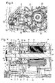
- the saw chain 6 is lubricated during operation with lubricating oil.
- oil tank 16 is provided in the oil tank 16.
- a suction head 18 is arranged, which is connected via a line 19 with an oil pump 15.
- the oil pump 15 has an oil pump sprocket 21 which is driven in rotation by a drive worm wheel 20.
- the longitudinal axis of the oil pump 15 and the axis of rotation of the drive worm wheel 20 are arranged perpendicularly and at a distance from one another.
- Fig. 4 shows the design of the drive of the power saw 1 in detail.
- a drive motor 26 which is designed as an electric motor, as an electronically commutated external rotor motor.
- the drive motor 26 has a rotor 27 which is rotatably connected to the drive shaft 25 at a connection 43.
- the connection 43 is arranged on the drive pinion remote from the end of the drive shaft 25.
- the drive shaft 25 is rotatably supported via a bearing 29 in a stator 28 of the drive motor 26.
- the stator 28 of the drive motor 26 is connected to a motor flange 34, on which an edge 37 is formed. In the edge 37, a bearing 24, namely a ball bearing, arranged, with which the drive shaft 25 is also mounted in rotation.
- the drive board 35 is also held for electronic commutation of the drive motor 26.
- the cup-shaped member 31 is disposed between the brake drum 8 and the bearing 24 on the drive shaft 25.
- the cup-shaped member 31 has an edge 30 which bears against the brake drum 8, and which is rotatably connected via driver 23 to the brake drum 8.
- the edge 30 is followed conical section 32, in which the outer diameter of the cup-shaped member 31 decreases with increasing distance from the brake drum 8.
- the conical section 32 is adjoined by the drive worm wheel 20, which is formed on the outer circumference of the cup-shaped component 31.
- the Antriebschneckenrad 20 extends to the bottom 40 of the cup-shaped member 31. The bottom 40 is penetrated by the drive shaft 25.
- the cup-shaped component 31 has a collar 41, which is cylindrical and aligned parallel to the drive shaft 25.
- a centering 22 is formed on the inner circumference of the collar 41.
- the collar 41 extends from the bottom 40 both into the interior of the cup-shaped member 31 and outwardly in the direction of the bearing 24.
- the collar 41 is located on the inner ring of the bearing 24 and is supported in the axial direction of this.
- the protruding into the interior of the cup-shaped member 31 portion of the collar 41 and the centering 22 is disposed radially within a portion of the drive worm wheel 20, so that there is a direct centering of the drive worm wheel 20.
- the drive shaft 25 in the region of the cup-shaped member 31 has an outer diameter a.
- the cup-shaped component 31 has an outer diameter b which is significantly greater than the outer diameter a of the drive shaft 25.
- the diameter b is at least approximately twice, advantageously at least approximately 2.5 times the outer diameter a of the drive shaft 25 ,
- the drive pinion 10 is formed integrally with the brake drum 8 as a sintered component.
- the brake drum 8 is wrapped on its outer periphery by a brake band 9, which extends over a large part of the outer circumference of the brake drum 8.
- the brake drum 8 is approximately cup-shaped. It has a flat bottom, which is perpendicular to the drive shaft 25, and a cylindrical portion 44 which extends into the interior of the housing 2 in the direction of the drive motor 26. On the cylindrical portion 44, the brake band 9 is arranged.
- the cup-shaped member 31 protrudes into the receiving space formed within the cylindrical portion 44, wherein the edge 30 of the cup-shaped component 31 bears against the bottom 45 of the brake drum 8 that is perpendicular to the drive shaft 25.
- the conical portion 32 is disposed substantially within the cylindrical portion 44.
- the drive shaft 25 has two flats 33 in the region of the drive pinion 10.
- the drive pinion 10 has an opening 39 which is also flattened and whose shape corresponds to the shape of the drive shaft 25 in the region of the flats 33, so that there is a positive, rotationally fixed connection.
- the drive worm wheel 20 is thus rotatably connected to the drive shaft 25 via the brake drum 8 and the drive pinion 10.
- the motor flange 34 has three mounting holes 36 for connection and rotationally fixed fixation on the housing 2.
- a plurality of carriers 23 are provided for connecting the cup-shaped member 31 to the brake drum 8.
- the driver 23 are bolt-shaped and formed on the cup-shaped member 31.
- the pot-shaped component is made of plastic and is manufactured together with the drivers 23 in an injection molding process.
- a smaller number of drivers 23 or only one driver 23 may be sufficient.
- the brake drum 8 has openings 38 which are positioned according to the drivers 23 and through which the drivers 23 are pushed during assembly.
- the drivers 23 and the openings 38 adjacent to the cylindrical portion 44 of the brake drum 8 are arranged.
- the radial distance of the driver 23 to the axis of rotation of the arrangement is chosen as large as possible, so that the transmittable torque is as large as possible.
- Fig. 4 shows has the edge 30th only a very small radial distance to the cylindrical portion 44. The edge 30 may also extend to the cylindrical portion 44.
- the wall thickness of the cup-shaped member 31 is substantially constant, so that there is a comparatively large interior of the cup-shaped member. This results in a low weight with high rigidity and strength.
Abstract
Description
Die Erfindung betrifft ein handgeführtes Arbeitsgerät der im Oberbegriff des Anspruchs 1 angegebenen Gattung.The invention relates to a hand-held implement of the type specified in the preamble of claim 1.
Aus der
Der Erfindung liegt die Aufgabe zugrunde, ein handgeführtes Arbeitsgerät der gattungsgemäßen Art zu schaffen, das einen einfachen Aufbau und eine lange Lebensdauer besitzt.The invention has for its object to provide a hand-held implement of the generic type, which has a simple structure and a long life.
Diese Aufgabe wird durch ein handgeführtes Arbeitsgerät mit den Merkmalen des Anspruchs 1 gelöst.This object is achieved by a hand-held implement with the features of claim 1.
Für die Lebensdauer der Schneckenradverzahnung ist die Genauigkeit der Positionierung von Antriebsschnecke und Ölpumpenritzel entscheidend. Die drehfeste Verbindung des topfförmigen Bauteils direkt mit der Bremstrommel und die Abstützung an der Antriebswelle an der gegenüberliegenden Seite des topfförmigen Bauteils führt zu einer sehr genauen Positionierung, ohne dass übermäßig genaue Fertigungstoleranzen einzuhalten sind. Aufgrund der topfförmigen Ausbildung des Bauteils kann der Außendurchmesser des Antriebsschneckenrads außerdem vergleichsweise groß ausgebildet werden.The accuracy of the positioning of the drive worm and the oil pump sprocket is decisive for the service life of the worm gear. The rotationally fixed connection of the pot-shaped component directly to the brake drum and the support on the drive shaft on the opposite side of the pot-shaped component leads to a very accurate positioning without excessively accurate manufacturing tolerances must be maintained. Due to the cup-shaped design of the component, the outer diameter of the drive worm wheel can also be made comparatively large.
Vorteilhaft ist die Abstützung an der Antriebswelle als Zentrierung ausgebildet. Dadurch, dass in diesem Bereich lediglich eine Abstützung und keine drehfeste Verbindung zur Antriebswelle vorgesehen ist, kann die Abstützung einfach und genau gefertigt werden, so dass eine gute Zentrierung gegeben ist. Durch die räumliche Trennung von Drehmitnahme und Zentrierung können außerdem Fertigungstoleranzen gut ausgeglichen werden. Vorteilhaft erstreckt sich die Zentrierung bis in den Bereich radial innerhalb des Antriebsschneckenrads, so dass sich für das Antriebsschneckenrad eine sehr genaue Zentrierung ergibt. Eine einfache Gestaltung ergibt sich, wenn die Zentrierung an einem Bund ausgebildet ist, der zylindrisch ausgebildet ist und die Antriebswelle umgibt. Der Bund stützt sich in axialer Richtung vorteilhaft auf der der Bremstrommel abgewandten Seite an einem Lager der Antriebswelle ab. Dadurch wird eine gute Positionierung in axialer Richtung der Antriebswelle erreicht. Zur Fixierung in Umfangsrichtung ist insbesondere vorgesehen, dass das topfförmige Bauteil mit der Bremstrommel formschlüssig über mindestens einen Mitnehmer verbunden ist. Insbesondere sind mehrere Mitnehmer über den Umfang verteilt angeordnet. Eine einfache Gestaltung mit wenigen Einzelteilen ergibt sich, wenn der oder die Mitnehmer an dem topfförmigen Bauteil angeformt sind. Die Mitnehmer können in entsprechende Aussparungen der Bremstrommel ragen und so auf einfache Weise eine drehfeste Verbindung herstellen. Da die Abstützung in axialer Richtung über den Bund des topfförmigen Bauteils erfolgt, muss die Drehmitnahme keine Fixierung in axialer Richtung bewirken.The support is advantageously formed on the drive shaft as a centering. The fact that only a support and no rotationally fixed connection to the drive shaft is provided in this area, the support can be made simple and accurate, so that a good centering is given. Due to the spatial separation of rotary driving and centering also manufacturing tolerances can be well balanced. Advantageously, the centering extends into the region radially inside the drive worm wheel, so that a very accurate centering results for the drive worm wheel. A simple design results when the centering is formed on a collar which is cylindrical and surrounds the drive shaft. The collar is supported in the axial direction advantageously on the side facing away from the brake drum on a bearing of the drive shaft. As a result, a good positioning in the axial direction of the drive shaft is achieved. For fixing in the circumferential direction is provided in particular that the cup-shaped member is positively connected to the brake drum via at least one driver. In particular, a plurality of drivers are arranged distributed over the circumference. A simple design with few individual parts results when the one or more drivers are integrally formed on the cup-shaped component. The drivers can protrude into corresponding recesses of the brake drum and thus easily establish a rotationally fixed connection. Since the support takes place in the axial direction over the collar of the pot-shaped component, the rotational drive does not cause any fixation in the axial direction.
Um einen großen Hebelarm für die Drehmomentübertragung und damit eine gute Krafteinleitung an der Befestigung zur Bremstrommel zu erreichen, ist vorgesehen, dass das topfförmige Bauteil zwischen Antriebsschneckenrad und Rand einen konischen Abschnitt besitzt, in dem sich der Außendurchmesser des topfförmigen Bauteils in Richtung auf den Rand vergrößert. Dadurch kann außerdem der zur Verfügung stehende Bauraum gut genutzt werden. Die Fixierung des topfförmigen Bauteils an der Bremstrommel wird dabei vorteilhaft so weit außen wie möglich angeordnet. Vorteilhaft ist das topfförmige Bauteil aus Kunststoff ausgebildet. Dadurch ergibt sich ein geringes Gesamtgewicht des Arbeitsgeräts. Durch die vorgeschlagene topfförmige Ausbildung wird auch bei einem Bauteil aus Kunststoff eine ausreichende Positionierungsgenauigkeit erreicht.In order to achieve a large lever arm for the torque transmission and thus a good introduction of force to the attachment to the brake drum, it is provided that the cup-shaped component between the drive worm wheel and edge has a conical section in which increases the outer diameter of the cup-shaped member in the direction of the edge , This also allows the available space to be used well. The fixation of the cup-shaped component on the brake drum is advantageously arranged as far outside as possible. The cup-shaped component is advantageously made of plastic. This results in a low total weight of the implement. Due to the proposed cup-shaped design sufficient positioning accuracy is achieved even with a plastic component.
Es ist vorgesehen, dass die Bremstrommel einen zylindrischen Abschnitt besitzt, der von einem Bremsband umschlungen ist. Um eine geringe Baugröße in axialer Richtung zu erreichen, ist insbesondere vorgesehen, dass das topfförmige Bauteil mindestes teilweise in den zylindrischen Abschnitt ragt. Die Bremstrommel ist dabei vorteilhaft etwa schalenförmig angeordnet, wobei der Rand der Bremstrommel das topfförmige Bauteil im Bereich des konischen Abschnitts übergreift. Eine einfache Gestaltung ergibt sich, wenn die drehfeste Verbindung zwischen Antriebswelle und Bremstrommel über mindestens eine Abflachung an der Antriebswelle erfolgt, die in eine entsprechend abgeflachte Öffnung in der Bremstrommel ragt. Die Abflachung erstreckt sich dabei vorteilhaft nur im Bereich der Bremstrommel und des Antriebsritzels und nicht in den Bereich des topfförmigen Bauteils. Dadurch kann der Bereich der Antriebswelle, der zylindrisch ausgebildet ist, lang ausgebildet werden. Dadurch ist eine Herstellung in einem vereinfachten Verfahren, beispielsweise ein spitzenloses Schleifen, möglich.It is envisaged that the brake drum has a cylindrical portion which is looped by a brake band. In order to achieve a small size in the axial direction, it is provided in particular that the pot-shaped component projects at least partially into the cylindrical portion. The brake drum is advantageously arranged approximately cup-shaped, wherein the edge of the brake drum engages over the cup-shaped member in the region of the conical portion. A simple design results when the rotationally fixed connection between the drive shaft and the brake drum via at least one flattening on the drive shaft, which projects into a correspondingly flattened opening in the brake drum. The flattening extends advantageous only in the region of the brake drum and the drive pinion and not in the region of the cup-shaped component. Thereby, the area of the drive shaft, which is cylindrical, can be made long. As a result, a production in a simplified process, for example, a centerless grinding, possible.
Die axiale Sicherung von Bremstrommel und topfförmigem Bauteil erfolgt vorteilhaft über einen Sicherungsring. Dadurch wird keine Klemmung der Bauteile auf der Antriebswelle benötigt, so dass sich eine weitere Vereinfachung des Aufbaus ergibt. Der Sicherungsring ist dabei insbesondere auf der dem topfförmigen Bauteil abgewandten Seite der Bremstrommel angeordnet.The axial securing of brake drum and pot-shaped component is advantageously carried out via a locking ring. As a result, no clamping of the components is required on the drive shaft, so that there is a further simplification of the structure. The securing ring is arranged in particular on the side facing away from the cup-shaped member of the brake drum.
Vorteilhaft ist das Werkzeug von einem Antriebsritzel angetrieben, das einteilig mit der Bremstrommel ausgebildet ist, und das auf der dem topfförmigen Bauteil abgewandten Seite an der Bremstrommel angeordnet ist. Die Bremstrommel ist vorteilhaft ein Sinterteil. Dabei ist insbesondere die Bremstrommel zusammen mit dem Antriebsritzel als ein gemeinsames Bauteil in einem Sinterverfahren hergestellt.Advantageously, the tool is driven by a drive pinion, which is formed integrally with the brake drum, and which is arranged on the side facing away from the cup-shaped member on the brake drum. The brake drum is advantageously a sintered part. In particular, the brake drum is produced together with the drive pinion as a common component in a sintering process.
Vorteilhaft ist das Arbeitsgerät eine Motorsäge, und das Werkzeug ist eine Sägekette.Advantageously, the implement is a power saw, and the tool is a saw chain.
Ein Ausführungsbeispiel der Erfindung wird im Folgenden anhand der Zeichnung erläutert. Es zeigen:
- Fig. 1
- eine perspektivische Darstellung einer Motorsäge,
- Fig. 2
- eine Seitenansicht auf die Motorsäge aus
Fig. 1 mit abgenommenem Kettenraddeckel, - Fig. 3
- eine perspektivische Darstellung der Ölpumpe der Motorsäge,
- Fig. 4
- eine ausschnittsweise Schnittdarstellung der Motorsäge im Bereich der Antriebswelle,
- Fig. 5
- eine perspektivische Darstellung des Antriebs der Motorsäge,
- Fig. 6
- eine Explosionsdarstellung des Antriebsschneckenrads und der Bremstrommel.
- Fig. 1
- a perspective view of a power saw,
- Fig. 2
- a side view of the chainsaw
Fig. 1 with removed sprocket cover, - Fig. 3
- a perspective view of the oil pump of the power saw,
- Fig. 4
- a partial sectional view of the chainsaw in the drive shaft,
- Fig. 5
- a perspective view of the drive of the power saw,
- Fig. 6
- an exploded view of the Antriebsschneckenrads and the brake drum.
Wie
Die Sägekette 6 wird im Betrieb mit Schmieröl geschmiert. Für das Schmieröl ist im Gehäuse 2 der in
Zwischen dem Lager 24 und dem Antriebsritzel 10 sind die Kupplungstrommel 8 und ein topfförmiges Bauteil 31 angeordnet. Das topfförmige Bauteil 31 ist zwischen der Bremstrommel 8 und dem Lager 24 an der Antriebwelle 25 angeordnet. Das topfförmige Bauteil 31 besitzt einen Rand 30, der an der Bremstrommel 8 anliegt, und der über Mitnehmer 23 mit der Bremstrommel 8 drehfest verbunden ist. An den Rand 30 schließt sich ein konischer Abschnitt 32 an, in dem sich der Außendurchmesser des topfförmigen Bauteils 31 mit zunehmender Entfernung von der Bremstrommel 8 verringert. An den konischen Abschnitt 32 schließt das Antriebsschneckenrad 20 an, das am Außenumfang des topfförmigen Bauteils 31 ausgebildet ist. Das Antriebsschneckenrad 20 erstreckt sich bis zum Boden 40 des topfförmigen Bauteils 31. Der Boden 40 ist von der Antriebswelle 25 durchragt. In dem die Antriebswelle 25 direkt umgebenen Bereich besitzt das topfförmige Bauteil 31 einen Bund 41, der zylindrisch ausgebildet und parallel zur Antriebswelle 25 ausgerichtet ist. Am Innenumfang des Bunds 41 ist eine Zentrierung 22 gebildet. Der Bund 41 erstreckt sich vom Boden 40 sowohl ins Innere des topfförmigen Bauteils 31 als auch nach außen in Richtung auf das Lager 24. Der Bund 41 liegt am Innenring des Lagers 24 an und stützt sich in axialer Richtung an diesem ab. Der ins Innere des topfförmigen Bauteils 31 ragende Abschnitt des Bunds 41 und der Zentrierung 22 ist radial innerhalb eines Abschnitts des Antriebsschneckenrads 20 angeordnet, so dass sich eine direkte Zentrierung des Antriebsschneckenrads 20 ergibt.Between the
Wie
Das Antriebsritzel 10 ist einteilig mit der Bremstrommel 8 als Sinterbauteil ausgebildet. Die Bremstrommel 8 ist an ihrem Außenumfang von einem Bremsband 9 umschlungen, das sich über einen Großteil des Außenumfangs der Bremstrommel 8 erstreckt.The
Die Bremstrommel 8 ist etwa schalenförmig ausgebildet. Sie besitzt einen ebenen Boden, der senkrecht zur Antriebswelle 25 steht, sowie einen zylindrischen Abschnitt 44, der sich ins Innere des Gehäuses 2 in Richtung auf den Antriebsmotor 26 erstreckt. Am zylindrischen Abschnitt 44 ist das Bremsband 9 angeordnet. Das topfförmige Bauteil 31 ragt in den innerhalb des zylindrischen Abschnitts 44 gebildeten Aufnahmeraum, wobei der Rand 30 des topfförmigen Bauteils 31 an dem senkrecht zur Antriebswelle 25 stehenden Boden 45 der Bremstrommel 8 anliegt. Dadurch, dass der zylindrische Abschnitt 44 das topfförmige Bauteil 31 übergreift, ergibt sich ein kompakter Aufbau. Wie
Zur drehfesten Verbindung von Antriebsritzel 10 und Bremstrommel 8 mit der Antriebswelle 25 besitzt die Antriebswelle 25 zwei Abflachungen 33 im Bereich des Antriebsritzels 10. Wie die Explosionsdarstellung in
Wie
Wie
Wie
Claims (16)
dadurch gekennzeichnet, dass das Antriebsschneckenrad (20) an einem topfförmigen Bauteil (31) ausgebildet ist, wobei der Rand (30) des topfförmigen Bauteils (31) drehfest mit der Bremstrommel (8) verbunden ist und wobei sich das topfförmige Bauteil (31) im Bereich seines Bodens (40) an der Antriebswelle (25) abstützt.Hand-guided implement with a drive motor (26) which drives a tool via a drive shaft (25), with a rotationally fixed to the drive shaft (25) associated brake drum (8) and with an oil pump (15) from the drive shaft (25) via a drive worm wheel (20) is driven,
characterized in that the drive worm wheel (20) on a cup-shaped member (31) is formed, wherein the edge (30) of the cup-shaped member (31) rotatably connected to the brake drum (8) and wherein the cup-shaped member (31) in Area of its bottom (40) on the drive shaft (25) is supported.
dadurch gekennzeichnet, dass die Abstützung an der Antriebswelle (25) als Zentrierung (22) ausgebildet ist.Working device according to claim 1,
characterized in that the support on the drive shaft (25) is designed as a centering (22).
dadurch gekennzeichnet, dass die Zentrierung (22) sich bis in den Bereich radial innerhalb des Antriebsschneckenrads (20) erstreckt.Working device according to claim 2,
characterized in that the centering (22) extends into the region radially inside the drive worm wheel (20).
dadurch gekennzeichnet, dass die Zentrierung (22) an einem Bund (41) ausgebildet ist, der zylindrisch ausgebildet ist und die Antriebswelle (25) umgibt.Tool according to claim 2 or 3,
characterized in that the centering (22) on a collar (41) is formed, which is cylindrical and surrounds the drive shaft (25).
dadurch gekennzeichnet, dass der Bund (41) sich auf der der Bremstrommel (8) abgewandten Seite in axialer Richtung an einem Lager (24) der Antriebswelle (25) abstützt.Working device according to claim 4,
characterized in that the collar (41) on the brake drum (8) facing away in the axial direction on a bearing (24) of the drive shaft (25) is supported.
dadurch gekennzeichnet, dass das topfförmige Bauteil (31) mit der Bremstrommel (8) in Umfangsrichtung formschlüssig über mindestens einen Mitnehmer (23) verbunden ist.Tool according to one of claims 1 to 5,
characterized in that the cup-shaped component (31) with the brake drum (8) in the circumferential direction is positively connected via at least one driver (23).
dadurch gekennzeichnet, dass der Mitnehmer (23) an dem topfförmigen Bauteil (31) angeformt ist.Working device according to claim 6,
characterized in that the driver (23) on the cup-shaped member (31) is integrally formed.
dadurch gekennzeichnet, dass das topfförmige Bauteil (31) zwischen dem Antriebsschneckenrad (20) und dem Rand (30) einen konischen Abschnitt (32) besitzt, in dem sich der Außendurchmesser des topfförmigen Bauteils (31) in Richtung auf den Rand (30) vergrößert.Tool according to one of claims 1 to 7,
characterized in that the cup-shaped member (31) between the drive worm wheel (20) and the edge (30) has a conical portion (32) in which increases the outer diameter of the cup-shaped member (31) in the direction of the edge (30) ,
dadurch gekennzeichnet, dass das topfförmige Bauteil (31) aus Kunststoff ist.Tool according to one of claims 1 to 8,
characterized in that the cup-shaped member (31) is made of plastic.
dadurch gekennzeichnet, dass die Bremstrommel (8) einen zylindrischen Abschnitt (44) besitzt, der von einem Bremsband (9) umschlungen ist.Tool according to one of claims 1 to 9,
characterized in that the brake drum (8) has a cylindrical portion (44) which is looped by a brake band (9).
dadurch gekennzeichnet, dass das topfförmige Bauteil (31) mindestens teilweise in den zylindrischen Abschnitt (44) ragt.Tool according to claim 10,
characterized in that the cup-shaped member (31) projects at least partially into the cylindrical portion (44).
dadurch gekennzeichnet, dass die drehfeste Verbindung zwischen Antriebswelle (25) und Bremstrommel (8) über mindestens eine Abflachung (33) an der Antriebswelle (25) erfolgt, die in eine entsprechend abgeflachte Öffnung (39) an der Bremstrommel (8) ragt.Tool according to one of claims 1 to 11,
characterized in that the rotationally fixed connection between the drive shaft (25) and the brake drum (8) via at least one flattening (33) on the drive shaft (25) which projects into a corresponding flattened opening (39) on the brake drum (8).
dadurch gekennzeichnet, dass die axiale Sicherung der Bremstrommel (8) und des topfförmigen Bauteils (31) über einen Sicherungsring (12) erfolgt.Tool according to one of claims 1 to 12,
characterized in that the axial securing of the brake drum (8) and the cup-shaped component (31) via a locking ring (12).
dadurch gekennzeichnet, dass das Werkzeug von einem Antriebsritzel (10) angetrieben ist, wobei das Antriebsritzel (10) einteilig mit der Bremstrommel (8) ausgebildet und auf der dem topfförmigen Bauteil (31) abgewandten Seite an der Bremstrommel (8) angeordnet ist.Tool according to one of claims 1 to 13,
characterized in that the tool is driven by a drive pinion (10), wherein the drive pinion (10) formed integrally with the brake drum (8) and on the cup-shaped member (31) facing away from the brake drum (8).
dadurch gekennzeichnet, dass die Bremstrommel (8) ein Sinterteil ist.Tool according to one of claims 1 to 14,
characterized in that the brake drum (8) is a sintered part.
dadurch gekennzeichnet, dass das Arbeitsgerät eine Motorsäge (1) und das Werkzeug eine Sägekette (6) ist.Tool according to one of claims 1 to 15,
characterized in that the implement is a power saw (1) and the tool is a saw chain (6).
Applications Claiming Priority (1)
| Application Number | Priority Date | Filing Date | Title |
|---|---|---|---|
| DE201010033489 DE102010033489A1 (en) | 2010-08-05 | 2010-08-05 | Hand-held implement |
Publications (3)
| Publication Number | Publication Date |
|---|---|
| EP2415570A2 true EP2415570A2 (en) | 2012-02-08 |
| EP2415570A3 EP2415570A3 (en) | 2012-09-12 |
| EP2415570B1 EP2415570B1 (en) | 2015-12-23 |
Family
ID=44675394
Family Applications (1)
| Application Number | Title | Priority Date | Filing Date |
|---|---|---|---|
| EP11006366.6A Active EP2415570B1 (en) | 2010-08-05 | 2011-08-03 | Manually operated work device |
Country Status (4)
| Country | Link |
|---|---|
| US (1) | US8904651B2 (en) |
| EP (1) | EP2415570B1 (en) |
| CN (1) | CN102371395B (en) |
| DE (1) | DE102010033489A1 (en) |
Cited By (2)
| Publication number | Priority date | Publication date | Assignee | Title |
|---|---|---|---|---|
| EP2666603A1 (en) * | 2012-05-22 | 2013-11-27 | Andreas Stihl AG & Co. KG | Motorised chain saw with a feed pump |
| EP2418055B1 (en) * | 2010-08-11 | 2018-01-03 | Andreas Stihl AG & Co. KG | Manually operated work device |
Families Citing this family (6)
| Publication number | Priority date | Publication date | Assignee | Title |
|---|---|---|---|---|
| JP5962046B2 (en) * | 2012-02-13 | 2016-08-03 | 日立工機株式会社 | Chain saw |
| US10011035B2 (en) * | 2015-02-23 | 2018-07-03 | Makita Corporation | Machining device and electric motor for the same |
| CN111376351A (en) * | 2018-12-28 | 2020-07-07 | 南京德朔实业有限公司 | Chain saw |
| JP7278853B2 (en) | 2019-04-23 | 2023-05-22 | 株式会社マキタ | chainsaw |
| WO2021108588A1 (en) | 2019-11-25 | 2021-06-03 | Milwaukee Electric Tool Corporation | Powered handheld cutting tool |
| EP3865264A1 (en) | 2020-02-14 | 2021-08-18 | Andreas Stihl AG & Co. KG | Handheld machining apparatus with electric drive motor |
Citations (1)
| Publication number | Priority date | Publication date | Assignee | Title |
|---|---|---|---|---|
| DE102005030389A1 (en) | 2004-07-01 | 2006-02-02 | Kioritz Corp., Oume | Oil pump mechanism for lubricating a chainsaw |
Family Cites Families (16)
| Publication number | Priority date | Publication date | Assignee | Title |
|---|---|---|---|---|
| US2172824A (en) * | 1939-03-20 | 1939-09-12 | John R Fitzgerald | Fishing reel |
| US3343927A (en) * | 1963-12-18 | 1967-09-26 | Motor Wheel Corp | Sintered metal brake drum |
| US3465063A (en) * | 1965-10-06 | 1969-09-02 | Shell Oil Co | Hydrogenated diolefin block copolymers |
| US3465603A (en) * | 1967-11-13 | 1969-09-09 | Kenneth Lindstrom | Brake adjusting mechanism |
| IT984992B (en) * | 1973-05-18 | 1974-11-20 | Bruni M | ANTIPOL VERE PROTECTION DEVICE IN DRIVE WHEEL REDUCTION GROUPS FOR LARGE AGRICULTURAL MACHINES |
| AU7037081A (en) * | 1980-08-08 | 1982-03-02 | Black & Decker Incorporated | Automatic oiling system for chain saw |
| DE3341834C3 (en) * | 1983-11-19 | 1996-11-21 | Stihl Maschf Andreas | Chainsaw |
| US4893407A (en) * | 1989-05-30 | 1990-01-16 | Blount, Inc. | Integral dust cover and pump drive |
| IT222220Z2 (en) * | 1989-11-08 | 1995-02-01 | Galatron Srl | PAIR OF PLATES TO CONTROL THE DISPENSING OF FLUID IN VITONE TYPE VALVES |
| JP2538515Y2 (en) * | 1991-01-28 | 1997-06-18 | 株式会社共立 | Chainsaw |
| DE4107110C2 (en) * | 1991-03-06 | 1999-06-02 | Stihl Maschf Andreas | Chain saw with a lubricating oil pump |
| DE4134640C1 (en) * | 1991-10-19 | 1993-05-06 | Fa. Andreas Stihl, 7050 Waiblingen, De | |
| JP3263280B2 (en) * | 1995-05-16 | 2002-03-04 | 株式会社マキタ | Chain stopping device for electric chainsaw |
| JPH09155803A (en) | 1995-12-08 | 1997-06-17 | Kioritz Corp | Power work machine |
| DE202006008733U1 (en) * | 2006-05-31 | 2007-10-11 | Dolmar Gmbh | Braking band holding |
| CN102741024B (en) * | 2010-02-11 | 2016-01-20 | 胡斯华纳有限公司 | There is the battery-driven electric tool of brushless electric machine |
-
2010
- 2010-08-05 DE DE201010033489 patent/DE102010033489A1/en not_active Withdrawn
-
2011
- 2011-08-03 EP EP11006366.6A patent/EP2415570B1/en active Active
- 2011-08-04 US US13/198,272 patent/US8904651B2/en active Active
- 2011-08-05 CN CN201110230285.4A patent/CN102371395B/en active Active
Patent Citations (1)
| Publication number | Priority date | Publication date | Assignee | Title |
|---|---|---|---|---|
| DE102005030389A1 (en) | 2004-07-01 | 2006-02-02 | Kioritz Corp., Oume | Oil pump mechanism for lubricating a chainsaw |
Cited By (4)
| Publication number | Priority date | Publication date | Assignee | Title |
|---|---|---|---|---|
| EP2418055B1 (en) * | 2010-08-11 | 2018-01-03 | Andreas Stihl AG & Co. KG | Manually operated work device |
| EP2666603A1 (en) * | 2012-05-22 | 2013-11-27 | Andreas Stihl AG & Co. KG | Motorised chain saw with a feed pump |
| JP2013241010A (en) * | 2012-05-22 | 2013-12-05 | Andreas Stihl Ag & Co Kg | Power chain saw including conveyance pump |
| RU2623620C2 (en) * | 2012-05-22 | 2017-06-28 | Андреас Штиль АГ унд Ко. КГ | Chain petrol saw with supply pump |
Also Published As
| Publication number | Publication date |
|---|---|
| CN102371395B (en) | 2015-12-16 |
| US8904651B2 (en) | 2014-12-09 |
| CN102371395A (en) | 2012-03-14 |
| DE102010033489A1 (en) | 2012-02-09 |
| EP2415570B1 (en) | 2015-12-23 |
| US20120030954A1 (en) | 2012-02-09 |
| EP2415570A3 (en) | 2012-09-12 |
Similar Documents
| Publication | Publication Date | Title |
|---|---|---|
| EP2415570B1 (en) | Manually operated work device | |
| EP2241781B2 (en) | Gear, in particular planetary gear with a flange and a hollow wheel | |
| EP1207982A1 (en) | Manual machine tool | |
| EP2622719B1 (en) | Connecting structure for mechanically connecting a first housing to a second housing | |
| DE102008041599A1 (en) | Switchable transmission in a hand tool | |
| WO2012150050A1 (en) | Adjustment drive for adjustment devices of a motor vehicle seat | |
| EP1539546B1 (en) | Bearing for wiper drives | |
| DE102007025468A1 (en) | Height adjustable spring bearing | |
| EP1639275A1 (en) | Bearing arrangement for at least one gearbox wheel | |
| EP2222498B1 (en) | Threaded spindle adjustment drive | |
| DE102008041443A1 (en) | Gear drive unit | |
| WO2008116690A1 (en) | Hand machine tool | |
| DE102010053027A1 (en) | Shaft adapter unit, gearbox and drive unit | |
| DE102007000313A1 (en) | Electric hand tool with spindle locking device | |
| DE102020131946B4 (en) | Transmission device with oil pan | |
| DE102017105512A1 (en) | Adjustment device for an internal combustion engine | |
| EP0069125A1 (en) | Starter for combustion engine. | |
| DE102009054929B4 (en) | Hand tool device | |
| DE10003773B4 (en) | Hand tool with a locking device for the drive shaft | |
| DE102017121215A1 (en) | Brushless electric motor | |
| WO2012104113A1 (en) | Window-lifter drive for a motor vehicle | |
| EP1902192B1 (en) | Device and method for fixing a gearbox drive unit to a motor vehicle bodywork part | |
| EP3447333A1 (en) | Transmission device for attaching to a drive shaft | |
| DE3235524A1 (en) | Holder for a roller-shutter drive | |
| DE10316181A1 (en) | Wiper unit especially for a motor vehicle has drive shaft with toothed end connected to oscillating crank |
Legal Events
| Date | Code | Title | Description |
|---|---|---|---|
| AK | Designated contracting states |
Kind code of ref document: A2 Designated state(s): AL AT BE BG CH CY CZ DE DK EE ES FI FR GB GR HR HU IE IS IT LI LT LU LV MC MK MT NL NO PL PT RO RS SE SI SK SM TR |
|
| AX | Request for extension of the european patent |
Extension state: BA ME |
|
| PUAI | Public reference made under article 153(3) epc to a published international application that has entered the european phase |
Free format text: ORIGINAL CODE: 0009012 |
|
| PUAL | Search report despatched |
Free format text: ORIGINAL CODE: 0009013 |
|
| AK | Designated contracting states |
Kind code of ref document: A3 Designated state(s): AL AT BE BG CH CY CZ DE DK EE ES FI FR GB GR HR HU IE IS IT LI LT LU LV MC MK MT NL NO PL PT RO RS SE SI SK SM TR |
|
| AX | Request for extension of the european patent |
Extension state: BA ME |
|
| RIC1 | Information provided on ipc code assigned before grant |
Ipc: B27B 17/08 20060101AFI20120807BHEP |
|
| 17P | Request for examination filed |
Effective date: 20130302 |
|
| GRAP | Despatch of communication of intention to grant a patent |
Free format text: ORIGINAL CODE: EPIDOSNIGR1 |
|
| INTG | Intention to grant announced |
Effective date: 20150722 |
|
| GRAS | Grant fee paid |
Free format text: ORIGINAL CODE: EPIDOSNIGR3 |
|
| GRAA | (expected) grant |
Free format text: ORIGINAL CODE: 0009210 |
|
| AK | Designated contracting states |
Kind code of ref document: B1 Designated state(s): AL AT BE BG CH CY CZ DE DK EE ES FI FR GB GR HR HU IE IS IT LI LT LU LV MC MK MT NL NO PL PT RO RS SE SI SK SM TR |
|
| REG | Reference to a national code |
Ref country code: GB Ref legal event code: FG4D Free format text: NOT ENGLISH |
|
| REG | Reference to a national code |
Ref country code: CH Ref legal event code: EP |
|
| REG | Reference to a national code |
Ref country code: IE Ref legal event code: FG4D Free format text: LANGUAGE OF EP DOCUMENT: GERMAN |
|
| REG | Reference to a national code |
Ref country code: AT Ref legal event code: REF Ref document number: 766336 Country of ref document: AT Kind code of ref document: T Effective date: 20160115 |
|
| REG | Reference to a national code |
Ref country code: DE Ref legal event code: R096 Ref document number: 502011008537 Country of ref document: DE |
|
| REG | Reference to a national code |
Ref country code: LT Ref legal event code: MG4D |
|
| REG | Reference to a national code |
Ref country code: NL Ref legal event code: MP Effective date: 20151223 |
|
| PG25 | Lapsed in a contracting state [announced via postgrant information from national office to epo] |
Ref country code: LT Free format text: LAPSE BECAUSE OF FAILURE TO SUBMIT A TRANSLATION OF THE DESCRIPTION OR TO PAY THE FEE WITHIN THE PRESCRIBED TIME-LIMIT Effective date: 20151223 Ref country code: HR Free format text: LAPSE BECAUSE OF FAILURE TO SUBMIT A TRANSLATION OF THE DESCRIPTION OR TO PAY THE FEE WITHIN THE PRESCRIBED TIME-LIMIT Effective date: 20151223 Ref country code: NO Free format text: LAPSE BECAUSE OF FAILURE TO SUBMIT A TRANSLATION OF THE DESCRIPTION OR TO PAY THE FEE WITHIN THE PRESCRIBED TIME-LIMIT Effective date: 20160323 |
|
| PG25 | Lapsed in a contracting state [announced via postgrant information from national office to epo] |
Ref country code: NL Free format text: LAPSE BECAUSE OF FAILURE TO SUBMIT A TRANSLATION OF THE DESCRIPTION OR TO PAY THE FEE WITHIN THE PRESCRIBED TIME-LIMIT Effective date: 20151223 Ref country code: GR Free format text: LAPSE BECAUSE OF FAILURE TO SUBMIT A TRANSLATION OF THE DESCRIPTION OR TO PAY THE FEE WITHIN THE PRESCRIBED TIME-LIMIT Effective date: 20160324 Ref country code: RS Free format text: LAPSE BECAUSE OF FAILURE TO SUBMIT A TRANSLATION OF THE DESCRIPTION OR TO PAY THE FEE WITHIN THE PRESCRIBED TIME-LIMIT Effective date: 20151223 Ref country code: LV Free format text: LAPSE BECAUSE OF FAILURE TO SUBMIT A TRANSLATION OF THE DESCRIPTION OR TO PAY THE FEE WITHIN THE PRESCRIBED TIME-LIMIT Effective date: 20151223 Ref country code: FI Free format text: LAPSE BECAUSE OF FAILURE TO SUBMIT A TRANSLATION OF THE DESCRIPTION OR TO PAY THE FEE WITHIN THE PRESCRIBED TIME-LIMIT Effective date: 20151223 Ref country code: SE Free format text: LAPSE BECAUSE OF FAILURE TO SUBMIT A TRANSLATION OF THE DESCRIPTION OR TO PAY THE FEE WITHIN THE PRESCRIBED TIME-LIMIT Effective date: 20151223 |
|
| PG25 | Lapsed in a contracting state [announced via postgrant information from national office to epo] |
Ref country code: CZ Free format text: LAPSE BECAUSE OF FAILURE TO SUBMIT A TRANSLATION OF THE DESCRIPTION OR TO PAY THE FEE WITHIN THE PRESCRIBED TIME-LIMIT Effective date: 20151223 Ref country code: IT Free format text: LAPSE BECAUSE OF FAILURE TO SUBMIT A TRANSLATION OF THE DESCRIPTION OR TO PAY THE FEE WITHIN THE PRESCRIBED TIME-LIMIT Effective date: 20151223 Ref country code: ES Free format text: LAPSE BECAUSE OF FAILURE TO SUBMIT A TRANSLATION OF THE DESCRIPTION OR TO PAY THE FEE WITHIN THE PRESCRIBED TIME-LIMIT Effective date: 20151223 |
|
| REG | Reference to a national code |
Ref country code: FR Ref legal event code: PLFP Year of fee payment: 6 |
|
| PG25 | Lapsed in a contracting state [announced via postgrant information from national office to epo] |
Ref country code: SK Free format text: LAPSE BECAUSE OF FAILURE TO SUBMIT A TRANSLATION OF THE DESCRIPTION OR TO PAY THE FEE WITHIN THE PRESCRIBED TIME-LIMIT Effective date: 20151223 Ref country code: PL Free format text: LAPSE BECAUSE OF FAILURE TO SUBMIT A TRANSLATION OF THE DESCRIPTION OR TO PAY THE FEE WITHIN THE PRESCRIBED TIME-LIMIT Effective date: 20151223 Ref country code: RO Free format text: LAPSE BECAUSE OF FAILURE TO SUBMIT A TRANSLATION OF THE DESCRIPTION OR TO PAY THE FEE WITHIN THE PRESCRIBED TIME-LIMIT Effective date: 20151223 Ref country code: PT Free format text: LAPSE BECAUSE OF FAILURE TO SUBMIT A TRANSLATION OF THE DESCRIPTION OR TO PAY THE FEE WITHIN THE PRESCRIBED TIME-LIMIT Effective date: 20160426 Ref country code: EE Free format text: LAPSE BECAUSE OF FAILURE TO SUBMIT A TRANSLATION OF THE DESCRIPTION OR TO PAY THE FEE WITHIN THE PRESCRIBED TIME-LIMIT Effective date: 20151223 Ref country code: SM Free format text: LAPSE BECAUSE OF FAILURE TO SUBMIT A TRANSLATION OF THE DESCRIPTION OR TO PAY THE FEE WITHIN THE PRESCRIBED TIME-LIMIT Effective date: 20151223 Ref country code: IS Free format text: LAPSE BECAUSE OF FAILURE TO SUBMIT A TRANSLATION OF THE DESCRIPTION OR TO PAY THE FEE WITHIN THE PRESCRIBED TIME-LIMIT Effective date: 20160423 |
|
| REG | Reference to a national code |
Ref country code: DE Ref legal event code: R097 Ref document number: 502011008537 Country of ref document: DE |
|
| PLBE | No opposition filed within time limit |
Free format text: ORIGINAL CODE: 0009261 |
|
| STAA | Information on the status of an ep patent application or granted ep patent |
Free format text: STATUS: NO OPPOSITION FILED WITHIN TIME LIMIT |
|
| PG25 | Lapsed in a contracting state [announced via postgrant information from national office to epo] |
Ref country code: DK Free format text: LAPSE BECAUSE OF FAILURE TO SUBMIT A TRANSLATION OF THE DESCRIPTION OR TO PAY THE FEE WITHIN THE PRESCRIBED TIME-LIMIT Effective date: 20151223 |
|
| 26N | No opposition filed |
Effective date: 20160926 |
|
| PG25 | Lapsed in a contracting state [announced via postgrant information from national office to epo] |
Ref country code: BE Free format text: LAPSE BECAUSE OF NON-PAYMENT OF DUE FEES Effective date: 20160831 |
|
| PG25 | Lapsed in a contracting state [announced via postgrant information from national office to epo] |
Ref country code: SI Free format text: LAPSE BECAUSE OF FAILURE TO SUBMIT A TRANSLATION OF THE DESCRIPTION OR TO PAY THE FEE WITHIN THE PRESCRIBED TIME-LIMIT Effective date: 20151223 |
|
| PG25 | Lapsed in a contracting state [announced via postgrant information from national office to epo] |
Ref country code: MC Free format text: LAPSE BECAUSE OF FAILURE TO SUBMIT A TRANSLATION OF THE DESCRIPTION OR TO PAY THE FEE WITHIN THE PRESCRIBED TIME-LIMIT Effective date: 20151223 |
|
| REG | Reference to a national code |
Ref country code: CH Ref legal event code: PL |
|
| PG25 | Lapsed in a contracting state [announced via postgrant information from national office to epo] |
Ref country code: LI Free format text: LAPSE BECAUSE OF NON-PAYMENT OF DUE FEES Effective date: 20160831 Ref country code: CH Free format text: LAPSE BECAUSE OF NON-PAYMENT OF DUE FEES Effective date: 20160831 |
|
| REG | Reference to a national code |
Ref country code: IE Ref legal event code: MM4A |
|
| PG25 | Lapsed in a contracting state [announced via postgrant information from national office to epo] |
Ref country code: IE Free format text: LAPSE BECAUSE OF NON-PAYMENT OF DUE FEES Effective date: 20160803 |
|
| REG | Reference to a national code |
Ref country code: FR Ref legal event code: PLFP Year of fee payment: 7 |
|
| PG25 | Lapsed in a contracting state [announced via postgrant information from national office to epo] |
Ref country code: LU Free format text: LAPSE BECAUSE OF NON-PAYMENT OF DUE FEES Effective date: 20160803 |
|
| REG | Reference to a national code |
Ref country code: AT Ref legal event code: MM01 Ref document number: 766336 Country of ref document: AT Kind code of ref document: T Effective date: 20160803 |
|
| PG25 | Lapsed in a contracting state [announced via postgrant information from national office to epo] |
Ref country code: AT Free format text: LAPSE BECAUSE OF NON-PAYMENT OF DUE FEES Effective date: 20160803 |
|
| PG25 | Lapsed in a contracting state [announced via postgrant information from national office to epo] |
Ref country code: HU Free format text: LAPSE BECAUSE OF FAILURE TO SUBMIT A TRANSLATION OF THE DESCRIPTION OR TO PAY THE FEE WITHIN THE PRESCRIBED TIME-LIMIT; INVALID AB INITIO Effective date: 20110803 Ref country code: CY Free format text: LAPSE BECAUSE OF FAILURE TO SUBMIT A TRANSLATION OF THE DESCRIPTION OR TO PAY THE FEE WITHIN THE PRESCRIBED TIME-LIMIT Effective date: 20151223 |
|
| PG25 | Lapsed in a contracting state [announced via postgrant information from national office to epo] |
Ref country code: MT Free format text: LAPSE BECAUSE OF FAILURE TO SUBMIT A TRANSLATION OF THE DESCRIPTION OR TO PAY THE FEE WITHIN THE PRESCRIBED TIME-LIMIT Effective date: 20151223 Ref country code: TR Free format text: LAPSE BECAUSE OF FAILURE TO SUBMIT A TRANSLATION OF THE DESCRIPTION OR TO PAY THE FEE WITHIN THE PRESCRIBED TIME-LIMIT Effective date: 20151223 Ref country code: MK Free format text: LAPSE BECAUSE OF FAILURE TO SUBMIT A TRANSLATION OF THE DESCRIPTION OR TO PAY THE FEE WITHIN THE PRESCRIBED TIME-LIMIT Effective date: 20151223 |
|
| PG25 | Lapsed in a contracting state [announced via postgrant information from national office to epo] |
Ref country code: BG Free format text: LAPSE BECAUSE OF FAILURE TO SUBMIT A TRANSLATION OF THE DESCRIPTION OR TO PAY THE FEE WITHIN THE PRESCRIBED TIME-LIMIT Effective date: 20151223 |
|
| REG | Reference to a national code |
Ref country code: FR Ref legal event code: PLFP Year of fee payment: 8 |
|
| PG25 | Lapsed in a contracting state [announced via postgrant information from national office to epo] |
Ref country code: AL Free format text: LAPSE BECAUSE OF FAILURE TO SUBMIT A TRANSLATION OF THE DESCRIPTION OR TO PAY THE FEE WITHIN THE PRESCRIBED TIME-LIMIT Effective date: 20151223 |
|
| PGFP | Annual fee paid to national office [announced via postgrant information from national office to epo] |
Ref country code: GB Payment date: 20230822 Year of fee payment: 13 |
|
| PGFP | Annual fee paid to national office [announced via postgrant information from national office to epo] |
Ref country code: FR Payment date: 20230824 Year of fee payment: 13 Ref country code: DE Payment date: 20230828 Year of fee payment: 13 |