EP2415400B1 - Montageeinheit, Sensoreinheit, Messvorrichtung und Sensorbefestigungsverfahren - Google Patents
Montageeinheit, Sensoreinheit, Messvorrichtung und Sensorbefestigungsverfahren Download PDFInfo
- Publication number
- EP2415400B1 EP2415400B1 EP11176743.0A EP11176743A EP2415400B1 EP 2415400 B1 EP2415400 B1 EP 2415400B1 EP 11176743 A EP11176743 A EP 11176743A EP 2415400 B1 EP2415400 B1 EP 2415400B1
- Authority
- EP
- European Patent Office
- Prior art keywords
- adhesive material
- living body
- sensor
- holding portions
- material layer
- Prior art date
- Legal status (The legal status is an assumption and is not a legal conclusion. Google has not performed a legal analysis and makes no representation as to the accuracy of the status listed.)
- Active
Links
Images





Classifications
-
- A—HUMAN NECESSITIES
- A61—MEDICAL OR VETERINARY SCIENCE; HYGIENE
- A61B—DIAGNOSIS; SURGERY; IDENTIFICATION
- A61B5/00—Measuring for diagnostic purposes; Identification of persons
- A61B5/68—Arrangements of detecting, measuring or recording means, e.g. sensors, in relation to patient
- A61B5/6801—Arrangements of detecting, measuring or recording means, e.g. sensors, in relation to patient specially adapted to be attached to or worn on the body surface
- A61B5/683—Means for maintaining contact with the body
- A61B5/6832—Means for maintaining contact with the body using adhesives
-
- A—HUMAN NECESSITIES
- A61—MEDICAL OR VETERINARY SCIENCE; HYGIENE
- A61B—DIAGNOSIS; SURGERY; IDENTIFICATION
- A61B5/00—Measuring for diagnostic purposes; Identification of persons
- A61B5/145—Measuring characteristics of blood in vivo, e.g. gas concentration or pH-value ; Measuring characteristics of body fluids or tissues, e.g. interstitial fluid or cerebral tissue
- A61B5/14532—Measuring characteristics of blood in vivo, e.g. gas concentration or pH-value ; Measuring characteristics of body fluids or tissues, e.g. interstitial fluid or cerebral tissue for measuring glucose, e.g. by tissue impedance measurement
-
- A—HUMAN NECESSITIES
- A61—MEDICAL OR VETERINARY SCIENCE; HYGIENE
- A61B—DIAGNOSIS; SURGERY; IDENTIFICATION
- A61B5/00—Measuring for diagnostic purposes; Identification of persons
- A61B5/145—Measuring characteristics of blood in vivo, e.g. gas concentration or pH-value ; Measuring characteristics of body fluids or tissues, e.g. interstitial fluid or cerebral tissue
- A61B5/1468—Measuring characteristics of blood in vivo, e.g. gas concentration or pH-value ; Measuring characteristics of body fluids or tissues, e.g. interstitial fluid or cerebral tissue using chemical or electrochemical methods, e.g. by polarographic means
- A61B5/1486—Measuring characteristics of blood in vivo, e.g. gas concentration or pH-value ; Measuring characteristics of body fluids or tissues, e.g. interstitial fluid or cerebral tissue using chemical or electrochemical methods, e.g. by polarographic means using enzyme electrodes, e.g. with immobilised oxidase
- A61B5/14865—Measuring characteristics of blood in vivo, e.g. gas concentration or pH-value ; Measuring characteristics of body fluids or tissues, e.g. interstitial fluid or cerebral tissue using chemical or electrochemical methods, e.g. by polarographic means using enzyme electrodes, e.g. with immobilised oxidase invasive, e.g. introduced into the body by a catheter or needle or using implanted sensors
-
- A—HUMAN NECESSITIES
- A61—MEDICAL OR VETERINARY SCIENCE; HYGIENE
- A61B—DIAGNOSIS; SURGERY; IDENTIFICATION
- A61B5/00—Measuring for diagnostic purposes; Identification of persons
- A61B5/68—Arrangements of detecting, measuring or recording means, e.g. sensors, in relation to patient
- A61B5/6846—Arrangements of detecting, measuring or recording means, e.g. sensors, in relation to patient specially adapted to be brought in contact with an internal body part, i.e. invasive
- A61B5/6847—Arrangements of detecting, measuring or recording means, e.g. sensors, in relation to patient specially adapted to be brought in contact with an internal body part, i.e. invasive mounted on an invasive device
- A61B5/6848—Needles
- A61B5/6849—Needles in combination with a needle set
-
- A—HUMAN NECESSITIES
- A61—MEDICAL OR VETERINARY SCIENCE; HYGIENE
- A61B—DIAGNOSIS; SURGERY; IDENTIFICATION
- A61B5/00—Measuring for diagnostic purposes; Identification of persons
- A61B5/145—Measuring characteristics of blood in vivo, e.g. gas concentration or pH-value ; Measuring characteristics of body fluids or tissues, e.g. interstitial fluid or cerebral tissue
- A61B5/14503—Measuring characteristics of blood in vivo, e.g. gas concentration or pH-value ; Measuring characteristics of body fluids or tissues, e.g. interstitial fluid or cerebral tissue invasive, e.g. introduced into the body by a catheter or needle or using implanted sensors
Definitions
- the present invention relates to a mount unit used for fixing a sensor that can be subcutaneously embedded into a living body, a sensor unit that uses the mount unit, a measurement apparatus including the mount unit and the sensor unit, and a method for fixing the sensor.
- CGM continuous glucose monitoring
- a sensor is disposed such that a portion thereof is embedded under the skin of a patient, and a signal such as a current value depending on the glucose concentration in the interstitial fluid under the skin is continuously output by the sensor. Then, the signal is converted into a blood sugar level using a measuring device or the like.
- a measuring device or the like With the CGM, it is possible to continuously measure blood sugar levels (for example, see JP 2008-062072A (see FIGS. 14, 17, 26 to 28D, and 33).
- the blood sugar level can be known by measuring a glucose concentration in interstitial fluid under the skin.
- JP 2008-062072A discloses a device (embedded device) that can punch a sensor toward the skin together with a puncture needle and embed the sensor under the skin.
- the embedded device includes a mechanism that punches out the sensor together with the puncture needle using a spring or the like and then pulls back only the puncture needle.
- a mount unit for mounting the sensor is disposed on the skin of the patient.
- the mount unit is fixed to the patient's skin with a double-sided tape.
- an embedded device on which the sensor and the puncture needle have been set is disposed in a predetermined position of the mount unit, and the sensor and the puncture needle together are punched into the skin by the embedded device.
- the puncture needle returns to its original position, but the sensor is positioned such that a portion provided with a connection terminal projects from the skin and the remaining portion is held under the skin.
- a control unit for controlling the sensor is disposed on the mount unit.
- the portion of the sensor that is provided with the terminal is sandwiched between the mount unit and the control unit, and the sensor is fixed to the patient with the mount unit.
- the terminal of the control unit is connected to the sensor terminal projecting from the skin, completing a CGM system.
- a signal obtained by the sensor is converted into a digital signal by the control unit, and the signal is further sent to an external measuring device by wireless or wired transmission.
- the measuring device calculates a specific glucose concentration based on the signal and displays the calculated value on a display screen.
- the senor is fixed to the patient with the mount unit and the portion of the sensor that is embedded under the skin is prevented from moving accidentally. This is because if the portion of the sensor that is embedded under the skin moves and the wound formed in the skin by the embedded device is thus enlarged, the body of the patient functions so as to cover the sensor with protein in order to heal the wound, resulting in a state in which accurate measurement cannot be conducted.
- the double-sided tape used for fixing the mount unit to the patient may require replacement.
- double-sided tape that requires replacement in not replaced, hygiene problems such as a skin irritation and development of bacteria occur. Also, if the double-sided tape that requires replacement is not replaced, a reduction in adhesion of the double-sided tape, peeling of the double-sided tape or the like due to the turnover of the skin make the fixation of the sensor with the mount unit unstable. Consequently, the portion of the sensor that is embedded under the skin moves and the wound in the skin is thus enlarged, also causing the above-described problem of impairing accurate measurement. To solve these problems, the double-sided tape needs to be replaced regularly
- US7460897 discloses a patient interface and a method of installing a patient interface for a spectroscopy kit on a patient.
- the patient interface includes a butterfly-shaped patient interface with a cap on top of the patient interface and in proximity to an optical head.
- WO2009154675 discloses an introducer for introducing a sensor into the body of a patient.
- the introducer connects to a sensor hub.
- the introducer needle is exposed.
- a needle cover and the needle move with respect to each other so that the needle cover substantially covers the needle, protecting a user from being injured by the needle.
- EP1707114 discloses a fluorescence measurement analytical kit that includes an adhesive fluorescence measurement patch, a fluorescent-light-emitting bead and a remote module.
- the adhesive fluorescence measurement patch has an adhesive sheet configured for removable adhesion to the user's body, a light emitter attached to the adhesive sheet, and a light detector attached to the adhesive sheet.
- the light emitter is configured for emitting light that is absorbed by the fluorescent light emitting bead while the light detector is configured for detecting fluorescent light emitted by the fluorescent light-emitting bead.
- An example of the object of the present invention is to provide a mount unit, a sensor unit, a measurement apparatus, and a sensor fixation method that can solve the above-described problems and allows for easy replacement of a fixing adhesive material layer, while preventing external force from being applied to the sensor.
- a mount unit includes: a main body portion that holds a placement of a portion of a sensor under the skin of a living body; and two or more holding portions attached to the main body portion, wherein each of the two or more holding portions includes an adhesive material layer capable of adhering to the living body and is movable so as to allow for selection between a state in which the adhesive material layer is in contact with the living body and a state in which the adhesive material layer is separate from the living body, wherein the main body portion comprises a mechanism that can change a contact position of at least one of the holding portions that is in contact with the living body, in a state in which the position of the sensor is held. Accordingly, it is possible to suppress a skin irritation of the living body that can be caused by a long period of contact between the skin and the adhesive material layer.
- the adhesive material layer of one holding portion is kept adhering to the living body, and another holding portion is moved in this state to detach the adhesive material layer of the other holding portion from the living body, and the detached adhesive material layer can be replaced with a new adhesive material layer. That is, according to the present invention, it is possible to replace an old adhesive material layer, with the sensor being fixed.
- the present invention allows for easy replacement of the fixing adhesive material layer, while preventing external force being applied to the sensor.
- each of the two or more holding portions is attached to the main body portion via a hinge mechanism, and mobilization of the holding portions with the hinge mechanism allows for selection between a state in which the adhesive material layer is in contact with the living body and a state in which the adhesive material layer is separate from the living body. According to this preferred mode, it is possible to simplify the structure of the mount unit, thus realizing a reduction in manufacturing costs.
- each of the two or more holding portions is attached to the main body portion so as to be movable in a direction toward the living body and a direction away from the living body, and movement of the holding portions allows for selection between a state in which the adhesive material layer is in contact with the living body and a state in which the adhesive material layer is separate from the living body. According to this mode as well, it is possible to simplify the structure of the mount unit, thus realizing a reduction in manufacturing costs.
- each of the two or more holding portions is attached to the main body portion so as to further be rotatable with respect to the main body portion. According to this mode as well, it is possible to simplify the structure of the mount unit, thus realizing a reduction in manufacturing costs. Further, combination of this mode with the above-described modes can further simplify the replacement work of the adhesive material layer in a more reliable manner.
- a plurality of the adhesive material layers are provided on an outer face of each of the two or more holding portions in the direction of rotation.
- the adhesive material layer can be replaced by simply rotating the holding portions.
- a sensor unit in another preferred mode, includes: a sensor of which a portion can be placed under the skin of a living body; and the above described mount unit for fixing the sensor to the living body.
- a measurement apparatus for measuring numeric information relating to a substance contained in at least one of interstitial fluid and blood that are under the skin of a living body
- a measurement apparatus includes: a sensor of which a portion can be placed under the skin and that generates a signal dependent on the numeric information; the above described mount unit for fixing the sensor to the living body; and a control unit that receives the signal generated by the sensor and executes processing that includes digital signal processing on the signal.
- control unit executes transmission processing for transmitting the signal that has been subjected to digital signal processing to an external measuring device.
- the signal can be converted into the numeric information by the external measuring device, and therefore the size of the control unit can be reduced.
- a sensor fixation method is a method for fixing, to a living body, a sensor of which a portion can be placed under the skin of the living body, the method including the steps of:
- each of the two or more holding portions is attached to the main body portion via a hinge mechanism, mobilization of the holding portions with the hinge mechanism allows for selection between a state in which the adhesive material layer is in contact with the living body and a state in which the adhesive material layer is separate from the living body, and, in step (c), the adhesive material layer that needs to be replaced is detached from the living body by mobilization of the holding portions with the hinge mechanism.
- each of the two or more holding portions is attached to the main body portion so as to be movable in a direction toward the living body and a direction away from the living body, movement of the holding portions allows for selection between a state in which the adhesive material layer is in contact with the living body and a state in which the adhesive material layer is separate from the living body, and, in step (c), the adhesive material layer that needs to be replaced is detached from the living body by movement of the holding portions.
- each of the two or more holding portions is attached to the main body portion so as to be rotatable with respect to the main body portion.
- a plurality of the adhesive material layers are provided on an outer face of each of the two or more holding portions in the direction of rotation, and, in step (c), a new adhesive material layer replacing the adhesive material layer that needs to be replaced is faced toward the living body by rotation of the holding portions, and thereafter the new adhesive material layer is adhered to the living body by movement of the holding portions.
- the mount unit, the sensor unit, the measurement apparatus, and the sensor fixation method according to the present invention allow for easy replacement of the fixing adhesive material layer, while preventing external force from being applied to the sensor.
- Example 1 of the present invention a mount unit, a sensor unit, a measurement apparatus, and a sensor fixation method according to Example 1 of the present invention will be described with reference to FIGS. 1 to 4 .
- FIGS. 1A to 1C show the configuration of a mount unit and a sensor unit according to Example 1 of the present invention: FIG. 1A being a perspective view; FIG. 1B being a plan view; and FIG. 1C being a bottom view.
- a sensor unit 30 includes a mount unit 10 and a sensor 20 of which a portion 20a is placed under the skin.
- the sensor 20 When the portion 20a is placed under the skin, the sensor 20 generates a signal according to numeric information relating to a substance contained in at least one of interstitial fluid and blood as will be described below with reference to FIG. 2 .
- a substance contained in at least one of interstitial fluid and blood as will be described below with reference to FIG. 2 .
- a substance is glucose.
- the mount unit 10 is used for fixing the sensor 20 to a living body, and includes a main body portion 11 and holding portions 12a to 12d.
- the main body portion 11 holds the placement of a portion of the sensor 20 under the skin of the living body.
- the main body portion 11 holds the sensor 20 at a portion (not shown) of the sensor 20 that is not embedded under the skin.
- the main body portion 11 holds the sensor 20 such that the portion 20a of the sensor that is to be embedded under the skin projects from the living body side (see FIG. 1C ) of the main body portion 11.
- the holding portions 12a to 12d are formed in an arm shape and attached to the main body portion 11. Also, each of the holding portions 12a to 12d includes an adhesive material layer 13 capable of adhering to the living body, and is movable so as to allow for selection between a state in which the adhesive material layer 13 is in contact with the living body and a state in which the adhesive material layer 13 is separate from the living body.
- the number of the holding portions in the example shown in FIGS. 1A to 1C is four, Example is not limited thereto. It suffices that the number of the holding portions is two or more.
- each of the holding portions 12a to 12d is attached so as to project from the side face of the main body portion 11 toward the periphery of the portion of the main body portion 11 on the living body side (see FIG. 1C ). Also, each of the holding portions 12a to 12d is attached to the main body portion 11 via a hinge mechanism 15, and mobilization of the holding portions with the hinge mechanism 15 allows for selection between the state in which the adhesive material layer 13 is in contact with the living body and the state in which the adhesive material layer 13 is separate from the living body.
- the holding portions 12a and 12c are in the state in which the adhesive material layer 13 is in contact with the living body.
- the holding portions 12b and 12d are in the state in which the adhesive material layer 13 is separate from the living body.
- a separator film 14 is attached to the adhesive material layers 13 of the holding portions 12b and 12d in order to protect the adhesive material layers 13.
- the separator films 14 are diagonally hatched. Note that illustration of the separator film 14 attached to the adhesive material layer 13 of the holding portion 12d is omitted.
- the mount unit 10 is adhered to the skin of a living body with the adhesive material layers 13 of the holding portions 12a and 12c, but the adhesive material layers 13 of both of these holding portions have been degraded.
- the separator films 14 attached to the adhesive material layers 13 of the holding portions 12b and 12d are detached.
- the holding portions 12b and 12d are moved so as to be lifted down such that the adhesive material layers 13 of the holding portions 12b and 12d are adhered to the living body.
- the holding portions 12a and 12c so as to be lifted up, it is possible to detach the degraded adhesive material layers 13 from the living body, while keeping the sensor 20 fixed.
- the adhesive material layer 13 may be a layer formed only of an adhesive material, or may be a double-sided adhesive tape.
- the double-sided adhesive tape include a double-sided adhesive tape in which an adhesive material layer is provided on either side of a base material formed of non woven fabric or the like.
- the adhesive material used in a layer formed only of an adhesive material and a double-sided adhesive tape include a hydrogel-based adhesive material and a silicone-based adhesive material.
- a silicone-based adhesive material can recover its viscosity by surface cleaning, and therefore an adhesive material layer or a double-sided adhesive tape for which a silicone-baced adhesive material is used can be used repeatedly.
- an adhesive material that can be detached by application of heat or voltage can be used as the adhesive material for forming the adhesive material layers 13 in Example 1.
- the adhesive material layers 13 By forming the adhesive material layers 13 with such an adhesive material, the adhesion between each of the holding portions and the skin can be selectively performed. Also, in this case, application of heat or voltage to the adhesive material layers 13 can be performed with a power source (not shown) of the mount unit.
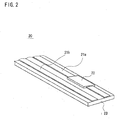
- FIG. 2 is a perspective view showing a tip portion of a sensor used in Example 1 of the present invention. The following description is given based on the assumption that the substance detected by the sensor 20 is glucose and the sensor 20 is a glucose sensor.
- the senor 20 is formed in the shape of an elongated band.
- the sensor 20 is brought into a state in which the portion 20a on the tip side is placed under the skin by an embedded device (not shown).
- Such a state of the sensor 20 can also be referred to as a state in which the sensor 20 is implanted in the skin.
- the senor 20 includes an insulating, flexible substrate 23.
- the material for forming the substrate 23 there is no particular limitation with respect to the material for forming the substrate 23.
- thermoplastic resins such as polyethylene terephthalate (PET), polypropylene (PP) and polyethylene (PE) and thermosetting resins such as polyimide resin and epoxy resin can be used as the material for forming the substrate 23 because these resins have little affect on the human body
- the shape of the substrate 23 may be, but is not particularly limited to, sharp-edged in order to facilitate the penetration into the skin of the living body.
- the sensor 20 includes a pair of electrodes 21a and 21b and a portion (enzyme reagent layer) 22 on which the glucose oxidoreductase is disposed.
- the electrodes 21a and 21b are used for applying voltage to the enzyme reagent layer 22.
- the electrodes 21a and 21b are formed on the surface of the substrate 23 in the longitudinal direction of the substrate 23, and also function as wiring. Additionally, the electrodes 21a and 21b may be formed by evaporation, screen printing, or the like, using, for example, a conductive material such as noncorrosive metal or carbon ink.
- the enzyme reagent layer 22 is formed by immobilizing glucose oxidoreductase on the electrode 21a.
- the electrode 21a functions as a working electrode.
- Glucose oxidoreductase has the function of detecting, on an electrode, a product resulting from the reaction with glucose (substrate) contained in interstitial fluid or blood, and the function of transferring electrons produced by the reaction to the electrode directly or via a mediator such as metal complex. Accordingly, upon application of voltage acaross the electrodes 21a and 21b, electrons produced by the catalyst reaction of the enzyme can be detected on electrode 21a according to the amount of glucose reacted in the reaction.
- glucose oxidoreductase examples include glucose oxidase (GOD) and glucose dehydrogenase (GDH).
- GOD glucose oxidase
- GDH glucose dehydrogenase
- Examples of the method for immobilizing glucose oxidoreductase include various known methods, including, for example, cross-linking using glutaraldehyde.
- the value of the electric current flowing through the electrodes 21a and 21b changes according to the glucose concentration, and therefore the glucose concentration can be identified by measuring the current.
- the current flowing through the electrodes 21a and 21b corresponds to "signal dependent on numeric information relating to a substance".
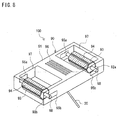
- FIG. 3 is a perspective view showing a measurement apparatus according to Example 1 of the present invention.
- a measurement apparatus 50 shown in FIG. 3 is an apparatus that measures numeric information relating to a substance contained in at least one of interstitial fluid and blood that are under the skin of a living body. As previously mentioned in the description in relation to FIGS. 1 and 2 , one example of such a substance is glucose. In this case, one example of the numeric information is glucose concentration.
- the measurement apparatus 50 includes the sensor unit 30 shown in FIGS. 1A to 1C and a control unit 40.
- the sensor unit 30 is disposed on the skin of a living body 60, and the tip portion 20a of the sensor 20 is placed under the skin of the living body 60.
- the control unit 40 includes a recess 42 for housing the sensor unit 30 and electrodes 41.
- the electrodes 41 are connected to the electrodes 16 of the mount unit 10 and are consequently also connected to the electrodes 21a and 21b (see FIG. 2 ) of the sensor 20.
- control unit 40 has the function of receiving a signal generated by the sensor 20 and executing the processing including digital signal processing on the received signal.
- processing examples include digital signal processing such as signal amplification processing and A/D conversion processing, and transmission processing.
- control unit 40 applies voltage to the electrodes 21a and 21b (see FIG. 2 ) of the sensor via the electrodes 16 of the mount unit 10.
- the control unit 40 monitors the value of the current flowing through the electrodes 21a and 21b. Then, the control unit 40 generates, by digital processing, a digital signal identifying the level of the current value.
- control unit 40 can transmit the generated digital signal to an external measuring device via wired or wireless transmission.
- this measuring device calculates a specific glucose concentration based on the received digital signal and displays the calculated value on a display screen or the like.
- the control unit 40 itself may perform the glucose concentration calculation and the like in this embodiment.
- FIGS. 4A to 4D show a series of main steps constituting a sensor fixation method according to Example 1. of the present invention.
- the sensor unit 30 is disposed on the skin of the living body 60, and the tip portion 20a of the sensor 20 is placed under the skin of the living body 60. Also, the mount unit 10 constituting the sensor unit 30 is adhered to the skin of the living body 60 with the adhesive material layers 13 of the holding portions 12a and 12c, but the adhesive material layers 13 of both of these holding portions have been degraded.
- the adhesive material layers 13 of the holding portions 12b and 12d are unused, and therefore the separator films 14 are attached to the adhesive material layers 13.
- the separator films 14 are diagonally hatched in FIG. 4A as well. However, illustration of the separator film 14 attached to the adhesive material layer 13 of the holding portion 12d is omitted.
- the holding portions 12b and 12d are lifted down such that the adhesive materials layers 13 of the holding portions 12b and 12d are adhered to the living body 60 as shown in FIG. 4B .
- the holding portions 12a and 12c are lifted up, and the degraded adhesive material layers 13 are detached from the living body 60.
- the degraded adhesive material layers 13 are removed from the holding portions 12a and 12c. Then, new adhesive material layers 13 are applied to the holding portions 12a and 12c. The new adhesive material layers 13 are used when the adhesive material layers 13 of the holding portions 12b and 12d have been degraded.
- Embodiment 1 it is possible to detach a degraded adhesive material layer 13 from the living body 60, while keeping the sensor 20 fixed. Furthermore, it is possible to replace a degraded adhesive material layer 13 with a new adhesive material layer, while keeping the sensor 20 fixed.
- Example 1 is not limited thereto.
- the mount unit 10 may be fixed using all of the holding portions 12a to 12d. In this case, with at least only one holding portion lifted down, the lifting-up of other holding portions and the replacement of the adhesive material layers 13 may be performed. Thereafter, the holding portions whose adhesive material layers 13 have been replaced may be lifted down, and the lifting-up of the remaining holding portions and the replacement of the adhesive material layers 13 may be performed. Accordingly, it is possible to replace all of the degraded adhesive material layer 13 with new adhesive material layers 13, while keeping the sensor 20 fixed.
- FIGS. 5A to 5D show the configuration of a mount unit and a sensor unit according to Embodiment 2 of the present invention: FIG. 5A being a perspective view; FIG. 5B being a front view; FIG. 5C being a side view; and FIG. 5D being a bottom view.
- a sensor unit 80 includes a mount unit 70 and a sensor 20 in Example 2.
- the sensor 20 is the same as the sensor described in Example 1 with reference to FIG. 2 .
- the mount unit 70 includes a main body portions 71.
- the main body portion 71 holds a portion (not shown) of the sensor 20 that is not embedded under the skin, as with the main body portion 11 of the mount unit 10 shown in FIGS.1 .
- the mount unit 70 includes holding portions as with the mount unit 10 shown in FIGS.1 , the holding portions of the mount unit 70 in Embodiment 2 are different in configuration from those in Example 1. The following description is focused on the difference between Example 2 and Example 1.
- the sensor unit 70 includes holding portions 72a and 72b unlike the mount unit 10 shown in FIGS. 1 .
- Each of the holding portions 72a and 72b is attached to the main body portion 71 so as to be movable in a direction toward the living body and a direction away from the living body in the projecting state (see FIGS. 5B and 5C ).
- each of the holding portions 72a and 72b is capable of moving vertically in the thickness direction of the main body portion 71. Then, movement of each of the holding portions 72a and 72b allows for selection between a state in which the adhesive material layer 73 is in contact with the living body and a state in which the adhesive material layer 73 is separate from the living body:
- Each of the holding portions 72a and 72b has the shape of a roller and is attached rotatable to the main body portion 71. Specifically, each of the holding portions 72a and 72b can also rotate about its axis in the projecting direction, that is, its axis expending from the portion attached to the main body portion 71 toward the tip end portion as the rotation axis (see FIGS. 5A and 5C ).
- a plurality of adhesive material layers 73 are provided on the outer face of each of the holding portions 72a and 72b in the direction of rotation.
- a separator film 74 is attached to unused adhesive material layers 73 for protecting the adhesive material layers 73.
- the separator films 74 are diagonally hatched.
- the number of the holding portions is two or more in Example 2 as well.
- the number of the holding portions may be three or more.
- the mount unit 70 may be fixed using only some of the holding portions (for example, two holding portions), or may be fixed using all of the holding portions.
- the measurement apparatus includes a sensor unit 80 and a control unit as with Example 1.
- the control unit may be the same as the control unit 40 shown in FIG. 3 in Example 1.
- the measurement apparatus according to Example 2 can be configured by attaching the control unit to the sensor unit 80.
- FIGS. 6A to 6D show a series of main steps constituting a sensor fixation method according to Example 2 of the present invention.
- the sensor unit 80 is disposed on the skin of the living body 60, and the tip portion 20a of the sensor 20 is placed under the skin of the living body 60. Also, the mount unit 70 constituting the sensor unit 80 is adhered to the skin of the living body 60 with one of the adhesive material layers 73 of each of the holding portions 72a and 72b, but the adhesive material layers 73 in use have been degraded.
- separator films 74 are attached to unused adhesive material layers 73 in the holding portions 72a and 72b.
- the separator films 74 are diagonally hatched in FIGS. 6A to 6D as well.
- the holding portion 72a is rotated, and the separator film 74 of an unused adhesive material layer 73 is detached. Thereafter, the holding portion 72a is further rotated, and thereby the adhesive material layer 73 from which the separator film 74 has been detached is faced toward the living body 60 instead of the degraded adhesive material layer 73a.
- the holding portion 72a is moved in the direction toward the living body 60, and thereby the adhesive material layer 73 from which the separator film 74 has been detached in the step shown in FIG. 6C is adhered to the living body 60.
- adhesion to the living body 60 is achieved by the new adhesive material layer 73 replacing the degraded adhesive material layer 73a in the holding portion 72a.
- adhesion to the living body 60 is achieved with the new adhesive material layer 73 replacing the degraded adhesive material layer in the holding portion 72b as well.
- Example 2 it is possible to detach the degraded adhesive material layer 73a (see FIGS. 6B and 6C ) from the living body 60, while keeping the sensor 20 fixed, as with Embodiment 1. Furthermore, it is possible to replace the degraded adhesive material layer 73a with a new adhesive material layer 73, while keeping the sensor 20 fixed. Furthermore, according to Example 2, it is possible to replace the degraded adhesive material layer 73a with a new adhesive material layer 73 by simply rotating the holding portion 72a or 72b.
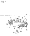
- FIG. 7 is a perspective view showing a modification of the mount unit according to Example 2 of the present invention.
- grooves 75 that permit the horizontal movement of the holding portions are provided on the side face of the main body portion 71.
- FIG. 7 only the groove 75 corresponding to the holding portion 72a is shown.
- this modification includes a mechanism that can change the contact position of at least one holding portion that is in contact with the living body, in a state where the position of the sensor 20 is held. This makes it possible to change the portion of the skin that is in contact with the adhesive material layer 73, without changing the position of the sensor 20. Accordingly, it is possible to suppress a skin irritation resulting from a long period of contact between the skin and the adhesive material layer 73.
- FIG. 8 shows the configuration of a mount unit according to Example 3 of the present invention.
- a sensor unit 100 includes a mount unit 90 and a sensor 20.
- the sensor 20 is the same as the sensor described in Example 1 with reference to FIG. 2 .
- the mount unit 90 includes a main body portion 91 to which holding portions 92a and 92b are attached. Further, as with the holding portions 72a and 72b shown in FIGS. 5A to 5D in Embodiment 2, the holding portions 92a and 92b have the shape of a roller and are attached rotatably to the main body portion 91.
- Example 3 a plurality of adhesive material layers 93 are provided on the outer face of each of the holding portions 92a and 92b in the direction of rotation as with Example 2. Accordingly it is possible to replace a degraded adhesive material layer with a new adhesive material layer 93 by simply rotating the holding portion 92a or 92b. Note that a separator film 94 is attached to unused adhesive material layers 93 for protecting the adhesive material layer 93. In FIG. 8 , the separator films 94 are diagonally hatched.
- Example 3 the holding portions 92a and 92b are attached inside the main body portion 91 in Example 3. Note that, for the sake of illustration, the part of the holding portions 92a and 92b that is actually hidden behind the main body portion 91 and thus cannot be visually observed is also shown in FIG. 8 .
- the main body portion 91 includes, on opposing side faces thereof, two sets of pairs of grooves 95a and 95b.
- Each of the holding portions 92a and 92b is held between a groove 95a and a groove 95b in a state in which it is sandwiched between the groove 95a and the groove 95b.
- each of the grooves 95a and 95b Sandwiching between the grooves 95a and 95b is achieved by catching, on the respective grooves, both ends of a shaft 98 passing through the center of each of the holding portions. Additionally, each of the grooves is formed in a rectangular shape in the horizontal direction of the main body portion 91, and the width of the grooves is set: to be greater than the diameter of the shaft 98.
- the mount unit 90 includes a mechanism that can change the contact position of at least one holding portion that is in contact with the living body, in a state in which the position of the sensor 20 is held.
- the number of the holding portions is two or more in Example 3 as well.
- the number of the holding portions may be three or more.
- the mount unit 90 may be fixed using only some of the holding portions (for example, two holding portions), or may be fixed using all of the holding portions.
- the measurement apparatus includes a sensor unit 90 and a control unit as with Example 1.
- the control unit may be the same as the control unit 40 shown in FIG. 3 in Example 1.
- the measurement apparatus according to Example 3 can be configured by attaching the control unit to the sensor unit 90.
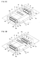
- FIGS. 9A an 9B show a series of main steps constituting a sensor fixation method according to Example 3 of the present invention.
- FIGS. 10C and 10D show a series of main steps constituting a sensor fixation method according to Example 3 of the present invention, which are executed after execution of the step shown in FIG. 9B .
- a sensor unit 100 is disposed on the skin of a living body 60, and the tip portion of the sensor 20 is placed under the skin of the living body 60.
- the mount unit 90 constituting the sensor unit 100 is adhered to the skin of the living body 60 with one of the adhesive material layers 93 of each of the holding portions 92a and 92b.
- the adhesive material layers 93a in use have been degraded and needs to be replaced.
- a separator film 94 is attached to unused adhesive material layers 93 of the holding portions 92a and 92b.
- the holding portion 92a is rotated, and the separator film 94 of an unused adhesive material layer 93 is detached. Thereafter, the holding portion 92a is further rotated, and thereby the adhesive material layer 93 from which the separator film 94 has been detached is faced toward the living body 60 instead of the degraded adhesive material layer 93a.
- the holding portion 92a is moved horizontally. Thereafter, the holding portion 92a is moved in the direction toward the living body 60, i.e., downward, before the adhesive material layer 93 from which the separator film 94 has been detached in the step shown in FIG. 10C is adhered to the living body 60. Thereafter the above-described upward motivation, detachment of the separator film, rotation, horizontal movement, and adhesion by the new adhesive material layer are similarly performed for the holding portion 92b as well.
- Example 3 it is possible to detach the degraded adhesive material layer 93a (see FIG. 9A ) from the living body 60 and replace the degraded adhesive material layer 93a with a new adhesive material layer 93, while keeping the sensor 20 fixed, as with Example 1.
- Example 3 it is possible to change the portion of the skin that is in contact with the adhesive material layer 93 by horizontal movement of the holding portions 92a and 92b, and therefore it is possible to suppress a skin irritation resulting from a long period of contact between the skin and the adhesive material layer 93, as with the modification of Example 2.
- the holding portions 92a and 92b are housed inside the main body portion 91, and therefore the detachment of the adhesive material layer 93 from the living body 60 due to external force applied to the holding portions 92a and 92b is also suppressed.
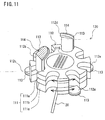
- FIG. 11 is a perspective view showing a mount unit according to Embodiment 4 of the present invention.
- a sensor unit 120 includes a mount unit 110 and a sensor 20 in Example 4.
- the sensor 20 is the same as the sensor described in Example 1 with reference to FIG. 2 .
- the mount unit 110 includes a main body portion 111 to which holding portions 112a to 112e are attached. As with the holding portions 12a to 12d shown in FIGS. 1 in Embodiment 1, the holding portions 112a to 112e are formed in an arm shape and attached to the side face of the main body portion 111 via a hinge mechanism (not shown in FIG. 11 ).
- mobilization of the holding portions with the hinge mechanism 15 allows for selection between the state in which the adhesive material layer 113 is in contact with the living body and the state in which the adhesive material layer 113 is separate from the living body Further, an adhesive material layer 113 capable of adhering to the living body is provided on the face of each holding portion on the living body side.
- the mount unit 110 includes movable holding portions in Example 4 as with the mount unit 10 shown in FIGS. 1 in Example 1.
- the mount unit 110 is different from the mount unit 10 in the following aspects.
- the mount unit 110 includes a mechanism that can change the contact position of at least one holding portion that is in contact with the living body, in a state in which the position of the sensor 20 is held.
- the main body portion 111 includes an upper portion 111a, a middle portion 111b, and a lower portion 111c.
- the upper portion 111a and the lower portion 111c are each attached to the middle portion 111b such that they are independently rotatable in the direction indicated by the arrows in FIG. 11 .
- the sensor 20 and electrodes 115 are attached to the middle portion 111b and remain stationary even if the upper portion 111a and the lower portion 111c are rotated.
- the holding portions 112a, 112c, and 112e are attached to the lower portion 111c. Also, the holding portions 112a, 112c, and 112e are formed so as not to prevent rotation of the upper portion 111a when they are separ ated from the living body (when they are lifted up).
- the holding portions 112b and 112d are attached to the upper portion 111a.
- the holding portions 112b and 112d are formed so as not to prevent rotation of the lower portion 111c when they are brought into contact with the living body (when they are lifted down).
- the holding portions 112b and 112d are formed so as to come into contact with the living body when they are lifted down, at positions further removed than the holding portion 112a, 112c, an 112e, so as not to come into contact with the lower portion 111c.
- the holding portions 112a, 112c, and 112e are in the state in which the adhesive material layers 113 are in contact with the living body.
- the holding portions 112b and 112d are in the state in which the adhesive material layers 113 are separate from the living body.
- a separator film 114 is attached to the adhesive material layers 113 of the holding portions 112b and 112d for protecting the adhesive material layers 113.
- the separator films 114 are diagonally hatched. Note that illustration of the separator film 114 attached to the adhesive material layer 13 of the holding portion 112d is omitted.
- FIGS. 12A to 12C show a series of main steps constituting a sensor fixation method according to Example 4 of the present invention.
- the sensor unit 120 is disposed on the skin of a living body 60, and the tip portion of the sensor 20 is placed under the skin of the living body 60.
- the mount unit 110 constituting the sensor unit 120 is adhered to the skin of the living body 60 with the adhesive material layers 113 of the holding portions 112a, 112c, and 112e.
- the adhesive material layers 113 of at least one of the holding portions 112a,112c, and 112e has been degraded and needs to be replaced.
- the adhesive material layers 113 of the holding portions 112b and 112d are unused, and therefore a separator film 114 is attached thereto.
- the holding portions 112b and 112d are lifted down and the adhesive material layers 113 thereof are adhered to the living body 60 as shown in FIG. 12B .
- the position of contact between each of the holding portions 112b and 112d and the living body 60 can be selected by rotating the upper portion 111a.
- the holding portions 112a, 112c, and 112e are brought into the lifted state (the state in which they are separate from the living body 60). Then, in this state, the degraded adhesive material layer 113 is replaced.
- the position of the contact between each of the holding portions 112a, 112c, and 112e and the living body 60 is selected by rotating the lower portion 111c, and then the holding portions 112a, 112c, and 112e are brought into contact with the living body 60 again. Then, the holding portions 112b and 112d are brought into the lifted state.
- Example 4 it is possible to detach a degraded adhesive material layer 113 from the living body 60, while keeping the sensor 20 fixed, as with Example 1. Furthermore, it is also possible to replace a degraded adhesive material layer 113 with a new adhesive material layer, while keeping the sensor 20 fixed.
- Example 4 the upper portion 111a and the lower portion 111c can be rotated independently, thus making it possible to change the portion of the living body that is in contact with the adhesive material layer 113, while keeping the sensor 20 fixed. Therefore, according to Example 4 as well, it is possible to suppress a skin irritation resulting from a long period of contact between the skin and the adhesive material layer 113, as with the modification of Example 2 and Example 3.
- the present invention in the case where adhesive tape or the like is used for fixing a mount of an embedded sensor to a living body it is possible to easily replace the adhesive tape while preventing external force from being applied to the sensor.
- the present device and method is particularly useful in the filed of CGM, in which such a demand exists.
Landscapes
- Health & Medical Sciences (AREA)
- Life Sciences & Earth Sciences (AREA)
- Physics & Mathematics (AREA)
- Biomedical Technology (AREA)
- Medical Informatics (AREA)
- Veterinary Medicine (AREA)
- Public Health (AREA)
- Biophysics (AREA)
- Pathology (AREA)
- Engineering & Computer Science (AREA)
- General Health & Medical Sciences (AREA)
- Heart & Thoracic Surgery (AREA)
- Animal Behavior & Ethology (AREA)
- Molecular Biology (AREA)
- Surgery (AREA)
- Optics & Photonics (AREA)
- Chemical & Material Sciences (AREA)
- Chemical Kinetics & Catalysis (AREA)
- General Chemical & Material Sciences (AREA)
- Emergency Medicine (AREA)
- Measurement Of The Respiration, Hearing Ability, Form, And Blood Characteristics Of Living Organisms (AREA)
- Measurement And Recording Of Electrical Phenomena And Electrical Characteristics Of The Living Body (AREA)
Claims (13)
- Montageeinheit (10), die Folgendes umfasst:einen Hauptkörperteil (11) zum Halten eines Teils eines Sensors (20) unter der Haut eines lebenden Körpers (60); undzwei oder mehr Halteteile (12a, 12b, 12c, 12d), die an dem Hauptkörperteil (11) angebracht sind,wobei jeder der zwei oder mehr Halteteile (12a, 12b, 12c, 12d) eine Klebstoffschicht (13) aufweist, die an dem lebenden Körper (60) haften kann und beweglich ist, um eine Auswahl zwischen einem Zustand, in dem die Klebstoffschicht (13) mit dem lebenden Körper (60) in Kontakt ist, und einem Zustand zu ermöglichen, in dem die Klebstoffschicht (13) von dem lebenden Körper (60) getrennt ist,wobei der Hauptkörperteil (11) einen Mechanismus umfasst, der eine Kontaktposition von wenigstens einem der Halteteile (12a, 12b, 12c, 12d), die mit dem lebenden Körper (60) in Kontakt sind, in einen Zustand ändern kann, in dem die Position des Sensors (20) gehalten wird.
- Montageeinheit (10) nach Anspruch 1,
wobei jeder der zwei oder mehr Halteteile (12a, 12b, 12c, 12d) über einen Gelenkmechanismus (15) an dem Hauptkörperteil (11) angebracht ist, und
eine Mobilisierung der Halteteile (12a, 12b, 12c, 12d) mit dem Gelenkmechanismus (15) das Auswählen zwischen einem Zustand, in dem die Klebstoffschicht (13) mit dem lebenden Körper (60) in Kontakt ist, und einem Zustand ermöglicht, in dem die Klebstoffschicht (13) von dem lebenden Körper (60) getrennt ist. - Montageeinheit (10) nach Anspruch 1,
wobei jeder der zwei oder mehr Halteteile (12a, 12b, 12c, 12d) so am Hauptkörperteil (11) angebracht ist, dass er in einer Richtung zu dem lebenden Körper (60) hin und in einer Richtung von dem lebenden Körper (60) weg beweglich ist, und
eine Bewegung der Halteteile (12a, 12b, 12c, 12d) eine Auswahl zwischen einem Zustand, in dem die Klebstoffschicht (13) mit dem lebenden Körper (60) in Kontakt ist, und einem Zustand ermöglicht, in dem die Klebstoffschicht (13) von dem lebenden Körper (60) getrennt ist. - Montageeinheit (10) nach Anspruch 3, wobei jeder der zwei oder mehr Halteteile (12a, 12b, 12c, 12d) so an dem Hauptkörperteil (11) angebracht ist, dass sie ferner mit Bezug auf den Hauptkörperteil (11) drehbar sind.
- Montageeinheit (10) nach Anspruch 4, wobei mehrere Klebstoffschichten (13) auf einer Außenfläche von jedem der zwei oder mehr Halteteile (12a, 12b, 12c, 12d) in der Drehrichtung vorgesehen sind.
- Sensoreinheit (30), die Folgendes umfasst: einen Sensor (20), von dem ein Teil unter der Haut eines lebenden Körpers (60) platziert werden kann; und die Montageeinheit (10) nach Anspruch 1 zum Befestigen des Sensors (20) an dem lebenden Körper (60).
- Messvorrichtung (50) zum Messen von numerischen Informationen in Bezug auf eine Substanz, die in interstitieller Flüssigkeit und/oder Blut enthalten ist, die sich unter der Haut eines lebenden Körpers (60) befindet/-n, wobei die Vorrichtung (50) Folgendes umfasst:einen Sensor (20), von dem ein Teil unter der Haut platziert werden kann und der so konfiguriert ist, dass er ein Signal in Abhängigkeit von den numerischen Informationen erzeugt;die Montageeinheit (10) nach Anspruch 1 zum Befestigen des Sensors (20) an dem lebenden Körper (60); undeine Steuereinheit (40) zum Empfangen des von dem Sensor (20) erzeugten Signals und zum Ausführen einer Verarbeitung, die Digitalsignalverarbeitung an dem Signal beinhaltet.
- Messvorrichtung (50) nach Anspruch 7, wobei die Steuereinheit (40) zum Ausführen einer Sendeverarbeitung zum Senden des Signals, das der Digitalsignalverarbeitung unterzogen wurde, zu einer externen Messvorrichtung ausgelegt ist.
- Sensorbefestigungsverfahren zum Befestigen, an einem lebenden Körper (60), eines Sensors (20), von dem ein Teil unter der Haut des lebenden Körpers (60) platziert werden kann, wobei das Verfahren die folgenden Schritte beinhaltet:(a) Verwenden einer Montageeinheit (10), die einen Hauptkörperteil (11) und zwei oder mehr an dem Hauptkörperteil (11) angebrachte Halteteile (12a, 12b, 12c, 12d) umfasst, wobei jeder der zwei oder mehr Halteteile (12a, 12b, 12c, 12d) eine Klebstoffschicht (13) aufweist, die an dem lebenden Körper (60) haften kann und am Hauptkörperteil (11) angebracht ist, um eine Auswahl zwischen einem Zustand, in dem die Klebstoffschichten (13) mit dem lebenden Körper (60) in Kontakt sind, und einem Zustand zu ermöglichen, in dem die Klebstoffschichten (13) von dem lebenden Körper (60) getrennt sind, und Halten des Sensors (20) durch den Hauptkörperteil (11) der Montageeinheit (10);(b) Befestigen der Montageeinheit (10) an dem lebenden Körper (60) durch Inkontaktbringen der Klebstoffschicht (13) von wenigstens einem der zwei oder mehr Halteteile (12a, 12b, 12c, 12d) der Montageeinheit (10) mit dem lebenden Körper (60); und(c) Bewegen, falls eine der Klebstoffschichten (13) der zwei oder mehr Halteteile (12a, 12b, 12c, 12d) ersetzt werden muss, des Halteteils (12a, 12b, 12c, 12d) einschließlich der zu ersetzenden Klebstoffschicht (13) in einen Zustand, in dem die Klebstoffschicht (13) von wenigstens einem der Halteteile (12a, 12b, 12c, 12d) mit dem lebenden Körper (60) in Kontakt ist, und Lösen der zu ersetzenden Klebstoffschicht (13) von dem lebenden Körper (60).
- Sensorbefestigungsverfahren nach Anspruch 9,
wobei jeder der zwei oder mehr Halteteile (12a, 12b, 12c, 12d) über einen Gelenkmechanismus (15) an dem Hauptkörperteil (11) angebracht ist,
eine Mobilisierung der Halteteile (12a, 12b, 12c, 12d) mit dem Gelenkmechanismus (15) eine Auswahl zwischen einem Zustand, in dem die Klebstoffschicht (13) mit dem lebenden Körper (60) in Kontakt ist, und einem Zustand ermöglicht, in dem die Klebstoffschicht (13) von dem lebenden Körper (60) getrennt ist, und
in Schritt (c) die zu ersetzende Klebstoffschicht (13) von dem lebenden Körper (60) durch Mobilisieren der Halteteile (12a, 12b, 12c, 12d) mit dem Gelenkmechanismus (15) gelöst wird. - Sensorbefestigungsverfahren nach Anspruch 9,
wobei jeder der zwei oder mehr Halteteile (12a, 12b, 12c, 12d) so an dem Hauptkörperteil (11) angebracht ist, dass er in einer Richtung zu dem lebenden Körper (60) hin und in einer Richtung von dem lebenden Körper (60) weg beweglich ist,
eine Bewegung der Halteteile (12a, 12b, 12c, 12d) eine Auswahl zwischen einem Zustand, in dem die Klebstoffschicht (13) mit dem lebenden Körper (60) in Kontakt ist, und einem Zustand ermöglicht, in dem die Klebstoffschicht (13) von dem lebenden Körper (60) getrennt ist, und
in Schritt (c) die zu ersetzende Klebstoffschicht (13) durch eine Bewegung der Halteteile (12a, 12b, 12c, 12d) von dem lebenden Körper (60) gelöst wird. - Sensorbefestigungsverfahren nach Anspruch 11, wobei jeder der zwei oder mehr Halteteile (12a, 12b, 12c, 12d) so am Hauptkörperteil (11) angebracht wird, dass er mit Bezug auf den Hauptkörperteil (11) gedreht werden kann.
- Sensorbefestigungsverfahren nach Anspruch 12,
wobei mehrere der Klebstoffschichten (13) auf einer Außenfläche von jedem der zwei oder mehr Halteteile (12a, 12b, 12c, 12d) in der Drehrichtung vorgesehen sind, und
in Schritt (c) eine neue Klebstoffschicht (13), die die zu ersetzende Klebstoffschicht (13) ersetzt, dem lebenden Körper (60) durch Drehen der Halteteile (12a, 12b, 12c, 12d) zugewandt wird, und danach die neue Klebstoffschicht (13) durch eine Bewegung der Halteteile (12a, 12b, 12c, 12d) auf den lebenden Körper (60) geklebt wird.
Applications Claiming Priority (1)
| Application Number | Priority Date | Filing Date | Title |
|---|---|---|---|
| JP2010176465 | 2010-08-05 |
Publications (2)
| Publication Number | Publication Date |
|---|---|
| EP2415400A1 EP2415400A1 (de) | 2012-02-08 |
| EP2415400B1 true EP2415400B1 (de) | 2015-10-07 |
Family
ID=44514550
Family Applications (1)
| Application Number | Title | Priority Date | Filing Date |
|---|---|---|---|
| EP11176743.0A Active EP2415400B1 (de) | 2010-08-05 | 2011-08-05 | Montageeinheit, Sensoreinheit, Messvorrichtung und Sensorbefestigungsverfahren |
Country Status (4)
| Country | Link |
|---|---|
| US (1) | US20120035441A1 (de) |
| EP (1) | EP2415400B1 (de) |
| JP (1) | JP5757816B2 (de) |
| CN (1) | CN102415887B (de) |
Families Citing this family (10)
| Publication number | Priority date | Publication date | Assignee | Title |
|---|---|---|---|---|
| WO2018067242A1 (en) * | 2016-10-03 | 2018-04-12 | Thomson Licensing | Detachable epidermal electronics |
| JP6892275B2 (ja) * | 2017-02-07 | 2021-06-23 | テルモ株式会社 | 生体情報検出装置 |
| US10722134B2 (en) * | 2017-12-27 | 2020-07-28 | X Development Llc | Gel-assisted electroencephalogram sensor electrode |
| US10716487B2 (en) | 2017-12-27 | 2020-07-21 | X Development Llc | Sub-dermally implanted electroencephalogram sensor |
| US10898137B2 (en) | 2017-12-27 | 2021-01-26 | X Development Llc | Gel-assisted electroencephalogram sensor electrode |
| US11647953B2 (en) | 2018-02-08 | 2023-05-16 | X Development Llc | Hair ratcheting electroencephalogram sensors |
| EP3749176B1 (de) | 2018-02-09 | 2025-12-03 | W. L. Gore & Associates, Inc. | Implantierbare zugriffskammer und zugehörige verwendungsverfahren |
| KR102200140B1 (ko) * | 2018-07-31 | 2021-01-11 | 주식회사 아이센스 | 연속 혈당 측정용 신체 부착 유닛 |
| CN111823293B (zh) * | 2020-07-20 | 2022-04-05 | 浙江凯立特医疗器械有限公司 | 一种植入性生物传感器的组装方法 |
| JP7325385B2 (ja) * | 2020-07-30 | 2023-08-14 | テルモ株式会社 | 留置デバイス |
Family Cites Families (12)
| Publication number | Priority date | Publication date | Assignee | Title |
|---|---|---|---|---|
| US6560471B1 (en) | 2001-01-02 | 2003-05-06 | Therasense, Inc. | Analyte monitoring device and methods of use |
| US20060258939A1 (en) * | 2003-06-09 | 2006-11-16 | Glucon, Inc. | Wearable glucometer |
| US7920906B2 (en) * | 2005-03-10 | 2011-04-05 | Dexcom, Inc. | System and methods for processing analyte sensor data for sensor calibration |
| EP1661516B1 (de) * | 2003-09-02 | 2012-08-15 | Koji Sode | Glukosesensor und glukosespiegel-messgerät |
| US20060224055A1 (en) * | 2005-03-30 | 2006-10-05 | Kermani Mahyar Z | Fluorescence measurement analytical kit |
| US7460897B1 (en) * | 2005-05-16 | 2008-12-02 | Hutchinson Technology Incorporated | Patient interface for spectroscopy applications |
| EP1972267A1 (de) * | 2007-03-20 | 2008-09-24 | Roche Diagnostics GmbH | System zur in-vivo Messung einer Analytkonzentration |
| US8641618B2 (en) * | 2007-06-27 | 2014-02-04 | Abbott Diabetes Care Inc. | Method and structure for securing a monitoring device element |
| US9295786B2 (en) * | 2008-05-28 | 2016-03-29 | Medtronic Minimed, Inc. | Needle protective device for subcutaneous sensors |
| JP5296446B2 (ja) | 2008-07-31 | 2013-09-25 | ビッグテクノス株式会社 | 電気剥離性粘着剤組成物、電気剥離性粘着製品及びその剥離方法 |
| JP2010176465A (ja) | 2009-01-30 | 2010-08-12 | Seiko Epson Corp | ジョブ制御装置 |
| WO2011037030A1 (ja) * | 2009-09-24 | 2011-03-31 | アークレイ株式会社 | 測定装置、及び測定方法 |
-
2011
- 2011-07-28 JP JP2011164885A patent/JP5757816B2/ja active Active
- 2011-08-02 US US13/196,540 patent/US20120035441A1/en not_active Abandoned
- 2011-08-03 CN CN201110221376.1A patent/CN102415887B/zh active Active
- 2011-08-05 EP EP11176743.0A patent/EP2415400B1/de active Active
Also Published As
| Publication number | Publication date |
|---|---|
| JP2012050809A (ja) | 2012-03-15 |
| JP5757816B2 (ja) | 2015-08-05 |
| EP2415400A1 (de) | 2012-02-08 |
| CN102415887A (zh) | 2012-04-18 |
| CN102415887B (zh) | 2016-03-02 |
| US20120035441A1 (en) | 2012-02-09 |
Similar Documents
| Publication | Publication Date | Title |
|---|---|---|
| EP2415400A1 (de) | Montageeinheit, Sensoreinheit, Messvorrichtung und Sensorbefestigungsverfahren | |
| US11457874B2 (en) | Display on a bandage-type monitoring device | |
| RU2528076C2 (ru) | Измерительный прибор и способ размещения датчика | |
| US20210228115A1 (en) | Wearable devices, wearable device forming methods, and methods of reuse of transmitter units of wearable devices in continuous analyte monitoring systems | |
| EP1411352A1 (de) | Analysevorrichtung, durchstechelement integral installierter körper für eine temperaturmesseinrichtung mit analysevorrichtung und körperflüssigkeitsprobennahmevorrichtung | |
| TW202000135A (zh) | 可撓式超低輪廓經皮連續監控感測器 | |
| CN1697627A (zh) | 生体成分测定装置 | |
| JP7770311B2 (ja) | 持続分析物モニタリングにおいて滅菌再利用可能なウェアラブル装置およびウェアラブル装置形成方法 | |
| RU2509532C2 (ru) | Измерительное устройство и способ измерения | |
| TWI893132B (zh) | 配置成傳送在連續的分析物監測器中的資料的發射器單元、可穿戴式裝置、確定分析物濃度的方法和製造基本單元的方法 | |
| EP2117421B1 (de) | Elektrochemischer testsensor mit lichtführung | |
| JP5899636B2 (ja) | バイオセンサ、バイオセンサカートリッジ、測定装置及び測定方法 | |
| JP4631030B2 (ja) | 針一体型バイオセンサー | |
| JP4682360B2 (ja) | 針一体型バイオセンサー | |
| JP5126756B2 (ja) | 穿刺器具一体型バイオセンサーおよびその製造法 | |
| JP4853947B2 (ja) | バイオセンサー | |
| JP4576628B2 (ja) | 針一体型バイオセンサー | |
| HK40077536A (en) | Sterilized reusable wearable devices and wearable device forming methods in continuous analyte monitoring | |
| HK40077079A (en) | Wearable devices, wearable device forming methods, and methods of reuse of transmitter units of wearable devices in continuous analyte monitoring systems | |
| JP4682361B2 (ja) | 穿刺器具一体型バイオセンサー | |
| HK40082149A (en) | Methods and apparatus configured to transmit data in continuous analyte monitors | |
| JP2007014646A (ja) | 針一体型バイオセンサー |
Legal Events
| Date | Code | Title | Description |
|---|---|---|---|
| AK | Designated contracting states |
Kind code of ref document: A1 Designated state(s): AL AT BE BG CH CY CZ DE DK EE ES FI FR GB GR HR HU IE IS IT LI LT LU LV MC MK MT NL NO PL PT RO RS SE SI SK SM TR |
|
| AX | Request for extension of the european patent |
Extension state: BA ME |
|
| PUAI | Public reference made under article 153(3) epc to a published international application that has entered the european phase |
Free format text: ORIGINAL CODE: 0009012 |
|
| 17P | Request for examination filed |
Effective date: 20120808 |
|
| GRAP | Despatch of communication of intention to grant a patent |
Free format text: ORIGINAL CODE: EPIDOSNIGR1 |
|
| INTG | Intention to grant announced |
Effective date: 20150522 |
|
| RAP1 | Party data changed (applicant data changed or rights of an application transferred) |
Owner name: ARKRAY, INC. |
|
| GRAS | Grant fee paid |
Free format text: ORIGINAL CODE: EPIDOSNIGR3 |
|
| GRAA | (expected) grant |
Free format text: ORIGINAL CODE: 0009210 |
|
| AK | Designated contracting states |
Kind code of ref document: B1 Designated state(s): AL AT BE BG CH CY CZ DE DK EE ES FI FR GB GR HR HU IE IS IT LI LT LU LV MC MK MT NL NO PL PT RO RS SE SI SK SM TR |
|
| REG | Reference to a national code |
Ref country code: GB Ref legal event code: FG4D |
|
| REG | Reference to a national code |
Ref country code: AT Ref legal event code: REF Ref document number: 753205 Country of ref document: AT Kind code of ref document: T Effective date: 20151015 Ref country code: CH Ref legal event code: EP |
|
| REG | Reference to a national code |
Ref country code: IE Ref legal event code: FG4D |
|
| REG | Reference to a national code |
Ref country code: DE Ref legal event code: R096 Ref document number: 602011020279 Country of ref document: DE |
|
| REG | Reference to a national code |
Ref country code: NL Ref legal event code: MP Effective date: 20151007 |
|
| REG | Reference to a national code |
Ref country code: AT Ref legal event code: MK05 Ref document number: 753205 Country of ref document: AT Kind code of ref document: T Effective date: 20151007 |
|
| REG | Reference to a national code |
Ref country code: LT Ref legal event code: MG4D |
|
| PG25 | Lapsed in a contracting state [announced via postgrant information from national office to epo] |
Ref country code: HR Free format text: LAPSE BECAUSE OF FAILURE TO SUBMIT A TRANSLATION OF THE DESCRIPTION OR TO PAY THE FEE WITHIN THE PRESCRIBED TIME-LIMIT Effective date: 20151007 Ref country code: NL Free format text: LAPSE BECAUSE OF FAILURE TO SUBMIT A TRANSLATION OF THE DESCRIPTION OR TO PAY THE FEE WITHIN THE PRESCRIBED TIME-LIMIT Effective date: 20151007 Ref country code: ES Free format text: LAPSE BECAUSE OF FAILURE TO SUBMIT A TRANSLATION OF THE DESCRIPTION OR TO PAY THE FEE WITHIN THE PRESCRIBED TIME-LIMIT Effective date: 20151007 Ref country code: NO Free format text: LAPSE BECAUSE OF FAILURE TO SUBMIT A TRANSLATION OF THE DESCRIPTION OR TO PAY THE FEE WITHIN THE PRESCRIBED TIME-LIMIT Effective date: 20160107 Ref country code: LT Free format text: LAPSE BECAUSE OF FAILURE TO SUBMIT A TRANSLATION OF THE DESCRIPTION OR TO PAY THE FEE WITHIN THE PRESCRIBED TIME-LIMIT Effective date: 20151007 Ref country code: IS Free format text: LAPSE BECAUSE OF FAILURE TO SUBMIT A TRANSLATION OF THE DESCRIPTION OR TO PAY THE FEE WITHIN THE PRESCRIBED TIME-LIMIT Effective date: 20160207 |
|
| PG25 | Lapsed in a contracting state [announced via postgrant information from national office to epo] |
Ref country code: FI Free format text: LAPSE BECAUSE OF FAILURE TO SUBMIT A TRANSLATION OF THE DESCRIPTION OR TO PAY THE FEE WITHIN THE PRESCRIBED TIME-LIMIT Effective date: 20151007 Ref country code: GR Free format text: LAPSE BECAUSE OF FAILURE TO SUBMIT A TRANSLATION OF THE DESCRIPTION OR TO PAY THE FEE WITHIN THE PRESCRIBED TIME-LIMIT Effective date: 20160108 Ref country code: SE Free format text: LAPSE BECAUSE OF FAILURE TO SUBMIT A TRANSLATION OF THE DESCRIPTION OR TO PAY THE FEE WITHIN THE PRESCRIBED TIME-LIMIT Effective date: 20151007 Ref country code: AT Free format text: LAPSE BECAUSE OF FAILURE TO SUBMIT A TRANSLATION OF THE DESCRIPTION OR TO PAY THE FEE WITHIN THE PRESCRIBED TIME-LIMIT Effective date: 20151007 Ref country code: LV Free format text: LAPSE BECAUSE OF FAILURE TO SUBMIT A TRANSLATION OF THE DESCRIPTION OR TO PAY THE FEE WITHIN THE PRESCRIBED TIME-LIMIT Effective date: 20151007 Ref country code: RS Free format text: LAPSE BECAUSE OF FAILURE TO SUBMIT A TRANSLATION OF THE DESCRIPTION OR TO PAY THE FEE WITHIN THE PRESCRIBED TIME-LIMIT Effective date: 20151007 Ref country code: PL Free format text: LAPSE BECAUSE OF FAILURE TO SUBMIT A TRANSLATION OF THE DESCRIPTION OR TO PAY THE FEE WITHIN THE PRESCRIBED TIME-LIMIT Effective date: 20151007 Ref country code: PT Free format text: LAPSE BECAUSE OF FAILURE TO SUBMIT A TRANSLATION OF THE DESCRIPTION OR TO PAY THE FEE WITHIN THE PRESCRIBED TIME-LIMIT Effective date: 20160208 |
|
| REG | Reference to a national code |
Ref country code: DE Ref legal event code: R097 Ref document number: 602011020279 Country of ref document: DE |
|
| PG25 | Lapsed in a contracting state [announced via postgrant information from national office to epo] |
Ref country code: CZ Free format text: LAPSE BECAUSE OF FAILURE TO SUBMIT A TRANSLATION OF THE DESCRIPTION OR TO PAY THE FEE WITHIN THE PRESCRIBED TIME-LIMIT Effective date: 20151007 |
|
| PLBE | No opposition filed within time limit |
Free format text: ORIGINAL CODE: 0009261 |
|
| STAA | Information on the status of an ep patent application or granted ep patent |
Free format text: STATUS: NO OPPOSITION FILED WITHIN TIME LIMIT |
|
| REG | Reference to a national code |
Ref country code: FR Ref legal event code: PLFP Year of fee payment: 6 |
|
| PG25 | Lapsed in a contracting state [announced via postgrant information from national office to epo] |
Ref country code: EE Free format text: LAPSE BECAUSE OF FAILURE TO SUBMIT A TRANSLATION OF THE DESCRIPTION OR TO PAY THE FEE WITHIN THE PRESCRIBED TIME-LIMIT Effective date: 20151007 Ref country code: SM Free format text: LAPSE BECAUSE OF FAILURE TO SUBMIT A TRANSLATION OF THE DESCRIPTION OR TO PAY THE FEE WITHIN THE PRESCRIBED TIME-LIMIT Effective date: 20151007 Ref country code: RO Free format text: LAPSE BECAUSE OF FAILURE TO SUBMIT A TRANSLATION OF THE DESCRIPTION OR TO PAY THE FEE WITHIN THE PRESCRIBED TIME-LIMIT Effective date: 20151007 Ref country code: SK Free format text: LAPSE BECAUSE OF FAILURE TO SUBMIT A TRANSLATION OF THE DESCRIPTION OR TO PAY THE FEE WITHIN THE PRESCRIBED TIME-LIMIT Effective date: 20151007 Ref country code: DK Free format text: LAPSE BECAUSE OF FAILURE TO SUBMIT A TRANSLATION OF THE DESCRIPTION OR TO PAY THE FEE WITHIN THE PRESCRIBED TIME-LIMIT Effective date: 20151007 |
|
| 26N | No opposition filed |
Effective date: 20160708 |
|
| PG25 | Lapsed in a contracting state [announced via postgrant information from national office to epo] |
Ref country code: SI Free format text: LAPSE BECAUSE OF FAILURE TO SUBMIT A TRANSLATION OF THE DESCRIPTION OR TO PAY THE FEE WITHIN THE PRESCRIBED TIME-LIMIT Effective date: 20151007 |
|
| PG25 | Lapsed in a contracting state [announced via postgrant information from national office to epo] |
Ref country code: BE Free format text: LAPSE BECAUSE OF FAILURE TO SUBMIT A TRANSLATION OF THE DESCRIPTION OR TO PAY THE FEE WITHIN THE PRESCRIBED TIME-LIMIT Effective date: 20151007 |
|
| PG25 | Lapsed in a contracting state [announced via postgrant information from national office to epo] |
Ref country code: MC Free format text: LAPSE BECAUSE OF FAILURE TO SUBMIT A TRANSLATION OF THE DESCRIPTION OR TO PAY THE FEE WITHIN THE PRESCRIBED TIME-LIMIT Effective date: 20151007 |
|
| REG | Reference to a national code |
Ref country code: CH Ref legal event code: PL |
|
| PG25 | Lapsed in a contracting state [announced via postgrant information from national office to epo] |
Ref country code: LI Free format text: LAPSE BECAUSE OF NON-PAYMENT OF DUE FEES Effective date: 20160831 Ref country code: CH Free format text: LAPSE BECAUSE OF NON-PAYMENT OF DUE FEES Effective date: 20160831 |
|
| REG | Reference to a national code |
Ref country code: IE Ref legal event code: MM4A |
|
| PG25 | Lapsed in a contracting state [announced via postgrant information from national office to epo] |
Ref country code: IE Free format text: LAPSE BECAUSE OF NON-PAYMENT OF DUE FEES Effective date: 20160805 |
|
| REG | Reference to a national code |
Ref country code: FR Ref legal event code: PLFP Year of fee payment: 7 |
|
| PG25 | Lapsed in a contracting state [announced via postgrant information from national office to epo] |
Ref country code: LU Free format text: LAPSE BECAUSE OF NON-PAYMENT OF DUE FEES Effective date: 20160805 |
|
| PG25 | Lapsed in a contracting state [announced via postgrant information from national office to epo] |
Ref country code: HU Free format text: LAPSE BECAUSE OF FAILURE TO SUBMIT A TRANSLATION OF THE DESCRIPTION OR TO PAY THE FEE WITHIN THE PRESCRIBED TIME-LIMIT; INVALID AB INITIO Effective date: 20110805 Ref country code: CY Free format text: LAPSE BECAUSE OF FAILURE TO SUBMIT A TRANSLATION OF THE DESCRIPTION OR TO PAY THE FEE WITHIN THE PRESCRIBED TIME-LIMIT Effective date: 20151007 |
|
| PG25 | Lapsed in a contracting state [announced via postgrant information from national office to epo] |
Ref country code: TR Free format text: LAPSE BECAUSE OF FAILURE TO SUBMIT A TRANSLATION OF THE DESCRIPTION OR TO PAY THE FEE WITHIN THE PRESCRIBED TIME-LIMIT Effective date: 20151007 Ref country code: MK Free format text: LAPSE BECAUSE OF FAILURE TO SUBMIT A TRANSLATION OF THE DESCRIPTION OR TO PAY THE FEE WITHIN THE PRESCRIBED TIME-LIMIT Effective date: 20151007 Ref country code: MT Free format text: LAPSE BECAUSE OF NON-PAYMENT OF DUE FEES Effective date: 20160831 |
|
| PG25 | Lapsed in a contracting state [announced via postgrant information from national office to epo] |
Ref country code: BG Free format text: LAPSE BECAUSE OF FAILURE TO SUBMIT A TRANSLATION OF THE DESCRIPTION OR TO PAY THE FEE WITHIN THE PRESCRIBED TIME-LIMIT Effective date: 20151007 |
|
| REG | Reference to a national code |
Ref country code: FR Ref legal event code: PLFP Year of fee payment: 8 |
|
| PG25 | Lapsed in a contracting state [announced via postgrant information from national office to epo] |
Ref country code: AL Free format text: LAPSE BECAUSE OF FAILURE TO SUBMIT A TRANSLATION OF THE DESCRIPTION OR TO PAY THE FEE WITHIN THE PRESCRIBED TIME-LIMIT Effective date: 20151007 |
|
| PGFP | Annual fee paid to national office [announced via postgrant information from national office to epo] |
Ref country code: DE Payment date: 20250820 Year of fee payment: 15 |
|
| PGFP | Annual fee paid to national office [announced via postgrant information from national office to epo] |
Ref country code: IT Payment date: 20250825 Year of fee payment: 15 |
|
| PGFP | Annual fee paid to national office [announced via postgrant information from national office to epo] |
Ref country code: GB Payment date: 20250820 Year of fee payment: 15 |
|
| PGFP | Annual fee paid to national office [announced via postgrant information from national office to epo] |
Ref country code: FR Payment date: 20250829 Year of fee payment: 15 |