EP2414901B1 - System und verfahren zum überwachen eines integrierten systems - Google Patents
System und verfahren zum überwachen eines integrierten systems Download PDFInfo
- Publication number
- EP2414901B1 EP2414901B1 EP10716652.2A EP10716652A EP2414901B1 EP 2414901 B1 EP2414901 B1 EP 2414901B1 EP 10716652 A EP10716652 A EP 10716652A EP 2414901 B1 EP2414901 B1 EP 2414901B1
- Authority
- EP
- European Patent Office
- Prior art keywords
- water purification
- purification system
- realtime
- parameters
- state
- Prior art date
- Legal status (The legal status is an assumption and is not a legal conclusion. Google has not performed a legal analysis and makes no representation as to the accuracy of the status listed.)
- Active
Links
Images


Classifications
-
- G—PHYSICS
- G05—CONTROLLING; REGULATING
- G05B—CONTROL OR REGULATING SYSTEMS IN GENERAL; FUNCTIONAL ELEMENTS OF SUCH SYSTEMS; MONITORING OR TESTING ARRANGEMENTS FOR SUCH SYSTEMS OR ELEMENTS
- G05B19/00—Program-control systems
- G05B19/02—Program-control systems electric
- G05B19/18—Numerical control [NC], i.e. automatically operating machines, in particular machine tools, e.g. in a manufacturing environment, so as to execute positioning, movement or co-ordinated operations by means of program data in numerical form
- G05B19/406—Numerical control [NC], i.e. automatically operating machines, in particular machine tools, e.g. in a manufacturing environment, so as to execute positioning, movement or co-ordinated operations by means of program data in numerical form characterised by monitoring or safety
- G05B19/4063—Monitoring general control system
-
- G—PHYSICS
- G05—CONTROLLING; REGULATING
- G05B—CONTROL OR REGULATING SYSTEMS IN GENERAL; FUNCTIONAL ELEMENTS OF SUCH SYSTEMS; MONITORING OR TESTING ARRANGEMENTS FOR SUCH SYSTEMS OR ELEMENTS
- G05B13/00—Adaptive control systems, i.e. systems automatically adjusting themselves to have a performance which is optimum according to some preassigned criterion
- G05B13/02—Adaptive control systems, i.e. systems automatically adjusting themselves to have a performance which is optimum according to some preassigned criterion electric
- G05B13/04—Adaptive control systems, i.e. systems automatically adjusting themselves to have a performance which is optimum according to some preassigned criterion electric involving the use of models or simulators
- G05B13/048—Adaptive control systems, i.e. systems automatically adjusting themselves to have a performance which is optimum according to some preassigned criterion electric involving the use of models or simulators using a predictor
-
- G—PHYSICS
- G05—CONTROLLING; REGULATING
- G05B—CONTROL OR REGULATING SYSTEMS IN GENERAL; FUNCTIONAL ELEMENTS OF SUCH SYSTEMS; MONITORING OR TESTING ARRANGEMENTS FOR SUCH SYSTEMS OR ELEMENTS
- G05B2219/00—Program-control systems
- G05B2219/30—Nc systems
- G05B2219/34—Director, elements to supervisory
- G05B2219/34477—Fault prediction, analyzing signal trends
-
- G—PHYSICS
- G05—CONTROLLING; REGULATING
- G05B—CONTROL OR REGULATING SYSTEMS IN GENERAL; FUNCTIONAL ELEMENTS OF SUCH SYSTEMS; MONITORING OR TESTING ARRANGEMENTS FOR SUCH SYSTEMS OR ELEMENTS
- G05B2219/00—Program-control systems
- G05B2219/30—Nc systems
- G05B2219/49—Nc machine tool, till multiple
- G05B2219/49181—Calculation, estimation, creation of error model using measured error values
-
- G—PHYSICS
- G05—CONTROLLING; REGULATING
- G05B—CONTROL OR REGULATING SYSTEMS IN GENERAL; FUNCTIONAL ELEMENTS OF SUCH SYSTEMS; MONITORING OR TESTING ARRANGEMENTS FOR SUCH SYSTEMS OR ELEMENTS
- G05B2219/00—Program-control systems
- G05B2219/30—Nc systems
- G05B2219/50—Machine tool, machine tool null till machine tool work handling
- G05B2219/50065—Estimate trends from past measured values, correct before really out of tolerance
Definitions
- the invention relates generally to a control system, and more particularly to a control system and method for monitoring an integrated system and predicting events leading to an expected state of the integrated system.
- One promising technology that enables significant reduction in power consumption and fresh water intake includes an integrated system having a water purification unit and a power generation unit.
- the power generation unit utilizes waste from the water purification unit to generate electrical power, and the integrated system operates on the electrical power generated by the power generation unit.
- excess power is used for some other application.
- An example of the integrated system is General Electric waste-to-value system that generates electricity and process steam (heat) in a flexible manner while recovering potable high-quality water.
- key units or components of a water purification system include a digester and a membrane bioreactor, while a key unit of a power generation system is a reciprocating gas engine or the like.
- the water purification system releases biogas as a waste that is consumed by the reciprocating gas engine to generate electrical power.
- the key units of the water purification system operate in a coordinated and an interdependent fashion, hence any upsets or variations in any key unit affect functionality and performance of the rest of the key units.
- the wastewater feed stream to the digester may have significant variations in flowrates, influent chemical oxygen demand, total suspended solids, total dissolved solids, temperature, nitrogen, phosphorous, sulphates and pH.
- the control system includes an estimator configured to determine a present state of a water purification system and compare the present state of the water purification system with an expected state of the water purification system.
- the control system also includes a predictor operatively coupled to the estimator, and configured to predict an event for execution by the water purification system to reach the expected state of the water purification system.
- the control system further includes a supervisory control unit operatively coupled to the predictor and the water purification system, and configured to facilitate execution of the predicted event by the water purification system.
- Another aspect of the invention provides a method for monitoring and controlling a water purification system in accordance with claim 12 herein.
- the method includes determining a present state of a water purification system utilizing system parameters, comparing the present state of the water purification system with an expected state of the water purification system to determine a difference between the present state of the water purification system and the expected state of the water purification system, predicting an event utilizing the difference between the present state of the water purification system and the expected state of the water purification system to reach the expected state of the water purification system, and executing the predicted event to reach the expected state of the water purification system.
- a method for monitoring and controlling a water purification system includes determining a realtime chemical oxygen demand of a feed stream of the water purification system using a realtime total organic carbon and color of the feed stream, determining realtime parameters of the feed stream of the water purification system, determining system parameters by applying one or more estimation techniques to the realtime parameters, predetermined parameters, offline parameters and the realtime chemical oxygen demand, determining a present state of the water purification system utilizing the system parameters, comparing the present state of the water purification system with an expected state of the water purification system to determine a difference between the present state of the water purification system and the expected state of the water purification system, and predicting an event utilizing the difference between the present state of the water purification system and the expected state of the water purification system to reach the expected state of the water purification system.
- a control system for monitoring and controlling a digester comprises an estimator configured to determine a present state of the digester.
- the estimator is further configured to compare the present state of the digester with an expected state of the digester.
- the system further includes a predictor operatively coupled to the estimator that is configured to predict an event for execution by the digester to reach the expected state of the digester.
- the system further includes a supervisory control unit operatively coupled to the predictor and the digester, and configured to facilitate execution of the predicted event by the digester.
- a system in accordance with a further aspect of the present technique, includes a water purification system and a control system.
- the water purification system includes a digester configured to extract substantial amounts of chemical oxygen demand from impure wastewater to generate chemical oxygen demand cleared water, one or more sensing devices operatively associated with the digester, and configured to sense realtime total organic carbon and realtime parameters of a feed stream of the digester.
- the water purification system further includes a membrane bioreactor operatively associated with the digester, and configured to generate an effluent by removal of substantial amounts of suspended impurities and any remaining chemical oxygen demand from the chemical oxygen demand cleared water.
- the water purification unit further includes a reverse osmosis unit operatively associated with the membrane bioreactor, and configured to remove soluble organics and total dissolved solids from the effluent.
- the control system is in operative association with the water purification system, and includes an estimator configured to determine a present state of the water purification system utilizing the realtime total organic carbon and the realtime parameters.
- the estimator is further configured to compare the present state of the water purification system with an expected state of the water purification system.
- the control system further includes a predictor operatively associated with the estimator, and configured to predict an event for execution by the water purification system to reach the expected state of the water purification system.
- the water purification system further includes a supervisory control unit operatively coupled to the predictor and the water purification system, and is configured to facilitate execution of the predicted event by the water purification system.
- FIG. 1 is a diagrammatical view of an exemplary system 10 for monitoring and controlling an integrated system 11, in accordance with aspects of the present technique.
- the integrated system 11 includes a water purification system with capabilities of recovering purified water and valuable energy.
- the water purification system 11 may include components, such as, a feed water unit 12, a first equalization tank 14, a first heat exchanger 15, a digester 16, a second equalization tank 27, a second heat exchanger 28, a membrane bioreactor 30, a reverse osmosis unit 32, a gas cleaning unit 18 and a power generation unit 22, or combinations thereof.
- a feed water unit 12 a first equalization tank 14, a first heat exchanger 15, a digester 16, a second equalization tank 27, a second heat exchanger 28, a membrane bioreactor 30, a reverse osmosis unit 32, a gas cleaning unit 18 and a power generation unit 22, or combinations thereof.
- the system 10 may also include a control system 40 configured to monitor and control the integrated system 11. As illustrated in FIG. 1 , the control system 40 is operatively associated with the integrated system 11. The monitoring and control of the integrated system 11 via the control system 40 enables continuous and consistent optimal operation of the integrated system 11.
- the feed water unit 12 is in operative association with the first equalization tank 14.
- the first equalization tank 14 is in operative association with the first heat exchanger 15 and the digester 16 is operatively coupled to the first heat exchanger 15.
- the feed water unit 12 intakes impure wastewater, and transfers the impure wastewater to the first equalization tank 14.
- the first equalization tank 14 may be configured to absorb variations in the amounts of impure wastewater.
- the impure wastewater from the first equalization tank 14 may then be transferred to the first heat exchanger 15.
- the first heat exchanger 15 regulates temperature of the impure wastewater to a predetermined temperature for an optimized working of the digester 16.
- the first heat exchanger 15 may include a shell and tube heat exchanger, a regenerative heat exchanger, an adiabatic wheel heat exchanger, a plate fin heat exchanger, a fluid heat exchanger, a dynamic scraped surface heat exchanger, a phase-change heat exchanger, a multi-phase heat exchanger, or a spiral heat exchanger, for example.
- the impure wastewater is transferred to the digester 16.
- the digester 16 may include an anaerobic digester. In an alternative embodiment, the digester 16 may include an aerobic digester.
- the digester 16 may include a sensing device 20 for sensing a total organic carbon (TOC) and realtime parameters of the impure wastewater received from the first heat exchanger 15.
- the digester 16 is shown as including the sensing device 20.
- the sensing device 20 may be incorporated in one or more of the components of FIG. 1 .
- the sensing device 20 may include a gas flow meter, a calorimeter, one or more hard sensors, and one or more soft sensors.
- realtime parameters may include parameters associated with the water and determined in realtime.
- the term “parameters” refers to measurable quantities and/or properties of the water that define purity of water.
- the realtime parameters for example, including others may include pH, TOC, bacterial concentration, microbial concentration, substrate concentration, temperature, biogas composition, alkalinity, hardness, amount of chlorides and phosphates, realtime color of feed stream, density of feed stream, and biogas quantity.
- the digester 16 may extract substantial amounts of chemical oxygen demand (COD) from the impure wastewater received from the first heat exchanger 15. Following the extraction of COD from the impure wastewater, the digester 16 generates a COD cleared water and releases biogas. Subsequently, the biogas is transferred to the gas cleaning unit 18 that cleans the biogas of impurities resulting in a purified biogas.
- the impurities may include gases other than biogas, such as H 2 S.
- the gas cleaning unit 18 then transfers the purified biogas to the power generation unit 22 that generates electrical power utilizing the purified biogas.
- the power generation unit 22 may include a reciprocating gas engine. In yet another embodiment, the power generation unit 22 may include a GE Jenbacher engine. Further, the electrical power generated by the power generation unit 22 may be utilized for operation of the integrated system 11. Also, in other embodiments, the electrical power may be utilized for operation of other industrial plants.
- the second equalization tank 27 may include a total suspended solids (TSS) removal system (not shown).
- TSS removal system may include entrapped air floatation system (EAF), dissolved air floatation system (DAF), belt press, screw press, or similar devices.
- temperature of the COD cleared water may be regulated in the second heat exchanger 28. Consequent to the regulation of temperature of the COD cleared water, a temperature regulated COD cleared water may be generated.
- the second heat exchanger 28, for example, may include a shell and tube heat exchanger, a regenerative heat exchanger, an adiabatic wheel heat exchanger, a plate fin heat exchanger, a fluid heat exchanger, a dynamic scraped surface heat exchanger, a phase-change heat exchanger, a multi-phase heat exchanger, or a spiral heat exchanger.
- the temperature regulated COD cleared water is transferred to the membrane bioreactor 30 that is in operative association with the second heat exchanger 28.
- the membrane bioreactor 30 facilitates removal of any remaining COD from the temperature regulated COD cleared water received from the second heat exchanger 28.
- the membrane bioreactor 30 also facilitates removal of substantial amounts of suspended impurities from the temperature regulated COD cleared water. Consequent to the removal of the remaining COD and suspended solids by the membrane bioreactor 30, an effluent is produced.
- the effluent is transferred to the reverse osmosis unit 32 that is in an operative association with the membrane bioreactor 30.
- the reverse osmosis unit 32 removes soluble organics and total dissolved solids (TDS) from the effluent. Consequent to the removal of the soluble organics and the TDS from the effluent, potable water is generated.
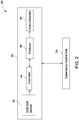
- FIG. 2 is a diagrammatical view illustrating one embodiment of the exemplary control system 40 for use with a device, in accordance with aspects of the present technique.
- the control system 40 may be configured to monitor and control the device for optimized and efficient working of the device.
- the device may include the integrated system 11 ( see FIG. 1 ).
- the device may include the digester 16 ( see FIG. 1 ), the membrane bioreactor 30 ( see FIG. 1 ), the first equalization tank 14 ( see FIG. 1 ), the first heat exchanger 15 ( see FIG. 1 ), the second equalization tank 27 ( see FIG. 1 ), the second heat exchanger 28 ( see FIG. 1 ), the power generation unit 22 ( see FIG. 1 ), or combinations thereof.
- control system 40 may include a supervisory control unit 24 and a control model 26.
- control model 26 may include a chemical oxygen demand soft sensor 42, an estimator 44, a predictor 46 and an event detector 48.
- the COD soft sensor 42 is in operational communication with the estimator 44.
- the COD soft sensor 42 may be configured to determine a realtime COD corresponding to a realtime total organic carbon (TOC) of a feed stream to the device.
- the realtime TOC may be determined by the sensing device 20 ( see FIG. 1 ).
- the COD soft sensor 42 may be configured to determine the realtime COD utilizing a COD model.
- the COD model may be built by mapping offline TOCs and color of the feed stream to corresponding offline CODs to determine a relationship between the offline TOCs and the realtime color of the feed stream and the corresponding offline CODs.
- the offline CODs and the offline TOCs may be determined by using COD laboratory tests and TOC laboratory tests, respectively.
- the color of the feed stream may be determined by the sensing device 20 ( see FIG. 1 ).
- the sensing device 20 for determining the color of the feed stream for example, may include the calorimeter.
- the relationship between the offline TOCs and the color of the feed stream to the corresponding offline CODs is determined by using artificial intelligence.
- the estimator 44 of the control model 26 may be configured to determine system parameters utilizing the realtime parameters, the realtime COD, offline parameters and predetermined parameters.
- the system parameters may include bacterial concentration, substrate concentration, microbial concentration, device COD, volatile fatty acids concentration, alkalinity, device TOC, hardness, ammonia concentration, phosphates concentrations, sulphates concentrations, biogas composition, device pH, or combinations thereof.
- predetermined parameters may be used to refer to parameters associated with the feed stream of the device while the device operates in a steady state condition. More particularly, the term “predetermined parameters" may be used to refer to the parameters of the feed stream of the device when the device operates in an optimized condition.
- predetermined parameters may be representative of steady state parameters of the device.
- offline parameters may be representative of the parameters that are determined offline.
- the offline parameters may be determined by utilizing laboratory tests.
- the offline parameters may include pH, the TOC, the COD, bacterial concentration (MLSS), substrate concentration, microbial concentration, nitrogen, phosphates concentration, sulphates concentration, temperature, biogas composition, alkalinity, hardness, amount of chlorides and, biogas quantity.
- the estimator 44 may be further configured to determine a present state of the device and compare the present state of the device with an expected state of the device. In one embodiment, the estimator 44 determines the present state of the device using the system parameters.
- the term "present state of the device” may be used to refer to an operating condition of the device.
- the term “expected state of the device” may be used to refer to a steady state operating condition of the device while the device operates in an optimized condition. In other words, the term “expected state of the device” may be used to refer to a state of the device when the system parameters are substantially similar to the predetermined parameters.
- the predictor 46 is operatively coupled to the estimator 44, and is configured to predict an event to be executed by the device to enable the device to reach a subsequent state of the device.
- the predicted event may include changes, variations or adjustments in concentrations, for example, change in pH, change in biomass concentration, change in alkalinity, change in inorganic carbon, change in nitrogen and phosphorous levels, change in hydrogen concentration, or combinations thereof.
- the event detector 48 is shown as being in operative association with the predictor 46 and the supervisory control unit 24.
- the event detector 48 is configured to determine the subsequent state of the device after execution of the predicted event.
- the event detector 48 may be configured to determine a corrective action for the device when the subsequent state of the device is different from the expected state of the device.
- the corrective action may include change in input feed rate, change in COD concentration, change in temperature, change in redox potential, change in nutrient addition, chemicals, addition, reseeding, and bioaugmentation. Consequent to the determination of the corrective action, the supervisory control unit 24 corrects the estimator 44 and the predictor 46.
- the supervisory control unit 24 corrects the predictor 46 and the estimator 44 by changing a state of the estimator 44 and the predictor 46.
- the state of the predictor 46 and the estimator 44 may be changed by determining the offline parameters, and updating the predictor 44 and the estimator 46 utilizing the offline parameters.
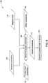
- reference numeral 62 is representative of feed.
- the feed 62 is similar to the realtime parameters.
- reference numeral 64 is representative of a set point.
- the set point 64 may be representative of the predetermined parameters.
- a first logic 66 receives as input feedback controls 78, the set point 64, feed forward controls 68, and the feed 62 to determine optimizing controls.
- the optimizing controls may be implemented by the supervisory control unit 24 on the integrated system 11 to enable optimized working of the integrated system 11.
- the event detector 48 is in operational communication with the integrated system 11.
- the event detector 48 may determine the subsequent state of the integrated system 11 after implementation of the optimizing controls.
- the subsequent state of the integrated system 11 may be representative of the feedback controls 78.
- the feedback controls 78 may include subsequent state controls that define the subsequent state of the integrated system 11 that is achieved after implementation of the optimizing controls by the supervisory control unit 24 on the integrated system 11.
- the optimizing controls may be representative of the predicted event.
- the corrective action may be representative of the feedback controls 78.
- a second logic 72 may be configured to receive the feed forward controls 68 and the set point 64.
- the second logic 72 transfers the feed forward controls 68 and the set point 64 to the control model 26.
- an offline analysis may be conducted by an offline processor 70 to determine the offline parameters.
- the control model 26 may determine the system parameters at step 74 and the present state of the integrated system 11 at step 76.
- the predictor 46 utilizes the system parameters and the present state of the integrated system 11 for determination of the predicted event.
- the predicted event may be representative of the feed forward controls 68.
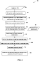
- FIG. 4 is a flow chart 80 illustrating an exemplary method for monitoring and controlling a device, such as integrated system 11 ( see FIG. 1 ), in accordance with aspects of the present technique.
- Reference numeral 82 may be representative of the realtime TOC.
- the realtime TOC may be determined by utilizing the sensing device 20 ( see FIG. 1 ).
- the method starts at step 84, where the realtime parameters may be determined using the sensing device 20 ( see FIG. 1 ).
- the realtime COD may be determined corresponding to the realtime TOC 82 and colors of the feed stream. As illustrated with reference to FIG. 1 , the colors of the feed stream may be one of the realtime parameters, and thus, may be determined by the sensing device 20 ( see FIG. 1 ).
- the determination of the realtime COD corresponding the realtime TOC and the colors of the feed stream may be better understood with reference to FIG. 5 .
- FIG. 5 a flow chart 110 illustrating an exemplary method of programming a soft sensor, such as the COD soft sensor 42 ( see FIG. 2 ), by building a chemical oxygen demand model, in accordance with aspects of the present technique is depicted.
- Reference numeral 112 may be representative of offline TOCs, while the colors of the feed stream may be represented by reference numeral 113. Further, reference numeral 114 may be representative of corresponding offline CODs.
- the method starts at step 116, where the offline TOCs 112 and the colors of the feed stream 113 are mapped to the corresponding offline CODs.
- a relationship between the offline TOCs 112 and the colors of the feed stream 113 to the corresponding offline CODs 114 is established.
- the relationship may be determined using artificial intelligence on the offline TOCs 112 and the colors of the feed stream 113 and the corresponding offline CODs 114.
- the relationship between the offline TOCs 112 and the colors of the feed stream 113 and the corresponding offline CODs 114 is used to build a COD model as indicated by step 118.
- the term "COD model” may be used to refer to a model capable of determining a realtime COD corresponding the realtime TOC.
- the COD soft sensor 42 may be programmed utilizing the COD model, as depicted in step 120.
- the COD soft sensor 42 may be used to determine the realtime CODs corresponding to the realtime TOCs and the colors of the feed stream.
- the realtime TOCs may be determined by the sensing device 20 ( see FIG. 1 ).
- the color of the feed stream may be determined by the calorimeter.
- a present state of the device is determined.
- the estimator 44 determines the present state of the device. The determination of the present state of the device may be better understood with reference to FIG. 6 .
- Reference numeral 132 may be representative of realtime parameters, while reference numeral 94 may be representative of predetermined parameters ( see FIG. 4 ). Also, reference numeral 138 may be representative of offline parameters, while reference numeral 134 may be representative of realtime COD 134.
- the method starts at step 140, where system parameters may be determined utilizing the realtime parameters 132, the offline parameters 138, the predetermined parameters 94, and the realtime COD 134. As previously noted with reference to FIG. 2 , the system parameters may be determined by the estimator 44.
- the system parameters may generally be represented by reference numeral 142.
- the estimator 44 may determine the system parameters 142 by application of mathematical formulas.
- equations (1) to (3) represent determination of the system parameters 142 by application of formulas.
- u X 1 , X 2 , X 3 , X 4 , X 5 , X 6 , X 7 ] T .
- subscript in is indicative of realtime parameters, offline parameters and/or predetermined parameters of the feed stream.
- the present state of the device may be determined at step 144. As previously noted with reference to FIG. 2 , the present state of the device may be determined by the estimator 44.
- the present state of the device determined at step 88 is compared with the expected state of the device. Further, the comparison of the present state of the device with the expected state of the device enables determination of a difference between the present state of the device and the expected state of the device.
- the expected state of the device may be determined by determining the predetermined parameters 94 ( see FIG. 6 ).
- an event is predicted at step 96, where the predicted event may enable the device to reach the expected state.
- the event is predicted by the predictor 46.
- the predictor 46 predicts the event such that implementation of the predicted event enables optimized working of the device. More particularly, the implementation of the predicted event enables the device to reach the expected state of the device.
- the predicted event may include heating or cooling of an input feed, addition of chemicals, increase or decrease in acidogenic bacterial concentration, increase or decrease in methanogenic bacterial concentration, increase or decrease in bacterial activity, fixing one or more components of the device, increase or decrease in oxygen content of the input feed, or combinations thereof, as previously noted.
- the device may be controlled to implement the predicted event as indicated by step 98.
- the supervisory control unit 24 controls the device to implement the predicted event. More particularly, the supervisory control unit 24 may be configured to control the device to implement the predicted event to enable the device reach the expected state.
- an impact of the implementation of the predicted event is determined.
- the impact of the predicted event is determined by determining the subsequent state ( see FIG. 2 ) of the device after implementation of the predicted event. As illustrated with reference to FIG. 2 , the event detector 48 ( see FIG. 2 ) determines the subsequent state of the device.
- corrective action to minimize any error in the prediction of the event may be determined at step 102.
- the event detector 48 may be configured to determine the corrective action.
- the corrective action may be determined when there is a need for corrective action. Determination of the need of the corrective action may be better understood with reference to FIG. 7 .
- FIG. 7 is a flowchart 150 illustrating a method for determining a need for a corrective action, in accordance with aspects of the present technique.
- Reference numeral 152 is representative of a predicted event.
- reference numeral 152 may be representative of the predicted event generated at step 96 ( see FIG. 4 ).
- the method starts at step 154 where a subsequent state of the device is determined. Further to the determination of the subsequent state, a check may be carried out at step 156 to determine whether the subsequent state of the device is similar to the expected state of the device. At step 156, if it is verified that the subsequent state of the device is substantially similar to the expected state of the device, then it may be concluded that no corrective action is necessary as indicated by reference numeral 160.
- step 156 if it is verified that the subsequent state of the device is different from the expected state of the device, then it may be concluded that corrective action may be desired, as indicated by the reference numeral 158.
- the event detector 48 may be configured to determine the corrective action.
- the corrective action may be implemented to minimize any error in the prediction of the event, as depicted by step 104.
- the corrective action is implemented by the supervisory control unit 24 ( see FIG. 2 ) to minimize an error in the prediction of the event.
- the supervisory control unit 24 implements the corrective action on the estimator 44 ( see FIG. 2 ) and the predictor 46 ( see FIG. 2 ), when there is a need for the corrective action.
- the present technique provides a realtime monitoring and controlling system for optimized working of the system and prevents the system from shutdowns. Further, the illustrated technique improves reliability of the device and reduces number of shutdowns of the device.
Landscapes
- Engineering & Computer Science (AREA)
- General Physics & Mathematics (AREA)
- Automation & Control Theory (AREA)
- Physics & Mathematics (AREA)
- Health & Medical Sciences (AREA)
- Manufacturing & Machinery (AREA)
- Human Computer Interaction (AREA)
- Artificial Intelligence (AREA)
- Computer Vision & Pattern Recognition (AREA)
- Evolutionary Computation (AREA)
- Medical Informatics (AREA)
- Software Systems (AREA)
- Feedback Control In General (AREA)
- Separation Using Semi-Permeable Membranes (AREA)
Claims (13)
- Steuerungssystem (40), welches konfiguriert ist, um ein Wasserreinigungssystem (11) zu überwachen und zu steuern, welches Folgendes beinhaltet:einen oder mehrere Sensoren (20), welche(r) konfiguriert ist/sind, um einen Echtzeitwert von organisch gebundenem Gesamtkohlenstoff (TOC) und Echtzeitparameter von verschmutztem Abwasser eines Zufuhrstroms eines Wasserreinigungssystems (11) zu bestimmen;einen weichen Sensor (42), welcher konfiguriert ist, um einen Echtzeitwert von chemischem Sauerstoffbedarf (CSB), welcher dem Echtzeitwert des organisch gebundenen Gesamtkohlenstoffs (TOC) des Zufuhrstroms des Wasserreinigungssystems (11) entspricht, unter Verwendung eines Modells für chemischen Sauerstoffbedarf zu bestimmen;ein Schätzgerät (44), welches in funktionstüchtiger Kommunikation mit dem weichen Sensor (42) steht und konfiguriert ist zum:Bestimmen eines augenblicklichen Zustandes des Wasserreinigungssystems (11) unter Verwendung des Echtzeitwertes des chemischen Sauerstoffbedarfs und der Echtzeitparameter;Vergleichen des augenblicklichen Zustandes des Wasserreinigungssystems (11) mit einem erwarteten Zustand des Wasserreinigungssystems;ein Vorhersagegerät (46), welches funktionstüchtig mit dem Schätzgerät (44) gekoppelt ist und konfiguriert ist, um ein Ereignis zur Ausführung durch das Wasserreinigungssystem (11) vorherzusagen, um den erwarteten Zustand des Wasserreinigungssystems zu erreichen; undeine Überwachungs-Steuerungseinheit (24), welche funktionstüchtig mit dem Vorhersagegerät (46) und dem Wasserreinigungssystem (11) gekoppelt ist und konfiguriert ist, um die Ausführung des vorhergesagten Ereignisses durch das Wasserreinigungssystem zu erleichtern.
- Steuerungssystem (40) nach Anspruch 1, bei welchem das Wasserreinigungssystem (11) Komponenten wie beispielsweise eine Wasserzufuhreinheit (12), einen ersten Ausgleichstank (14), einen ersten Wärmetauscher (15), einen Faulbehälter (16), einen zweiten Ausgleichstank (27), einen zweiten Wärmetauscher (28), einen Membranbioreaktor (30), eine Umkehrosmoseeinheit (32), eine Gasreinigungseinheit (18) und eine Energie-erzeugungseinheit (22) oder Kombinationen hieraus umfasst.
- Steuerungssystem (40) nach Anspruch 1, bei welchem die Wasserreinigungssystemvorrichtung (11) mindestens einen Faulbehälter (16), einen Membranebioreaktor (30), eine Umkehrosmoseeinheit (32) und einen oder mehrere Sensoren (20) umfasst, welche(r) konfiguriert ist/sind, um Echtzeitparameter und einen Echtzeitwert von organisch gebundenem Gesamtkohlenstoff aus einem Zufuhrstrom zum Wasserreinigungssystem (11) zu bestimmen.
- Steuerungssystem (40) nach Anspruch 1, bei welchem der weiche Sensor (42) ein Modell für chemischen Sauerstoffbedarf verwendet.
- Steuerungssystem (40) nach Anspruch 4, bei welchem das Modell für chemischen Sauerstoffbedarf durch Zuordnung eines Offlinewertes von organisch gebundenem Gesamtkohlenstoff und von Farben des Zufuhrstroms zu einem entsprechenden Offlinewert von chemischem Sauerstoffbedarf, wobei die Farben des Zufuhrstroms das Echtzeitparameter sind, konstruiert wird.
- Steuerungssystem (40) nach Anspruch 1, bei welchem das Schätzgerät (44) zudem konfiguriert ist, um Offlineparameter und vorbestimmte Parameter zu verwenden, wobei die vorbestimmten Parameter stationäre Parameter des Wasserreinigungssystems (11) darstellen und die Offlineparameter die offline bestimmten Parameter des Wasserreinigungssystems (11) darstellen.
- Steuerungssystem (40) nach Anspruch 1, bei welchem das vorhergesagte Ereignis eine Änderung des pH-Wertes des Wasserreinigungssystems (11), eine Änderung der Biomassenkonzentration, eine Änderung der Alkalinität, eine Änderung in anorganischem Kohlenstoff, eine Änderung der Stickstoff- und Phosphorspiegel, eine Änderung der Wasserstoffkonzentration oder Kombinationen hieraus beinhaltet.
- Steuerungssystem (40) nach Anspruch 1, zudem beinhaltend einen Ereignisdetektor (48), welcher funktionstüchtig mit der Überwachungs-Steuerungseinheit (24) und dem Schätzgerät (46) gekoppelt ist.
- Steuerungssystem (40) nach Anspruch 8, bei welchem der Ereignisdetektor (48) konfiguriert ist, um einen Folgezustand des Wasserreinigungssystems (11) nach Ausführung des vorhergesagten Ereignisses zu bestimmen.
- Steuerungssystem (40) nach Anspruch 9, bei welchem der Ereignisdetektor (48) konfiguriert ist, um eine Korrekturmaßnahme zu bestimmen, wenn der Folgezustand des Wasserreinigungssystems (11) sich von dem erwarteten Zustand des Wasserreinigungssystems unterscheidet.
- Steuerungssystem (40) nach Anspruch 10, bei welchem der Ereignisdetektor (48) konfiguriert ist, um die Korrekturmaßnahme an die Überwachungs-Steuerungseinheit (24) zu kommunizieren.
- Verfahren zur Überwachung und Steuerung eines Wasserreinigungssystems (11), welches Folgendes beinhaltet:Bestimmen eines Echtzeitwertes von organisch gebundenem Gesamtkohlenstoff (TOC) und von Echtzeitparametem von verschmutztem Abwasser eines Zufuhrstroms eines Wasserreinigungssystems (11) unter Verwendung eines Sensors oder mehrerer Sensor(en) 20;Bestimmen (86) eines Echtzeitwertes von chemischem Sauerstoffbedarf (CSB) anhand des Echtzeitwertes von organisch gebundenem Gesamtkohlenstoff (TOC) des Zufuhrstroms des Wasserreinigungssystems (11), unter Verwendung eines Modells für chemischen Sauerstoffbedarf;Bestimmen (88) eines augenblicklichen Zustandes des Wasserreinigungssystems (11) unter Verwendung des Echtzeitwertes des chemischen Sauerstoffbedarfs und der Echtzeitparameter;Vergleichen (90) des aktuellen Zustandes des Wasserreinigungssystems (11) mit einem erwarteten Zustand des Wasserreinigungssystems zum Bestimmen einer Differenz zwischen dem aktuellen Zustand des Wasserreinigungssystems und dem erwarteten Zustand des Wasserreinigungssystems;Vorhersagen (96) eines Ereignissees unter Verwendung der Differenz zwischen dem aktuellen Zustand des Wasserreinigungssystems (11) und dem erwarteten Zustand des Wasserreinigungssystems zum Erreichen des erwarteten Zustandes des Wasserreinigungssystems; undAusführen (98) des vorhergesagten Ereignisses zum Erreichen des erwarteten Zustandes des Wasserreinigungssystems (11).
- Verfahren nach Anspruch 12, bei welchem Bestimmen des aktuellen Zustandes des Wasserreinigungssystems (11) Folgendes beinhaltet:Bestimmen von Echtzeitparametern der Einspeisezufuhr des Wasserreinigungssystems; undAnwenden einer oder mehrerer Schätztechniken auf die Echtzeitparameter, die vorbestimmten Parameter und den Echtzeitwert von chemischem Sauerstoffbedarf, wobei die vorbestimmten Parameter stationäre Parameter des Wasserreinigungssystems darstellen und die Offlineparameter die offline bestimmten Parameter des Wasserreinigungssystems darstellen.
Applications Claiming Priority (2)
| Application Number | Priority Date | Filing Date | Title |
|---|---|---|---|
| US12/414,092 US8216517B2 (en) | 2009-03-30 | 2009-03-30 | System and method for monitoring an integrated system |
| PCT/US2010/026457 WO2010117526A1 (en) | 2009-03-30 | 2010-03-08 | System and method for monitoring an integrated system |
Publications (2)
| Publication Number | Publication Date |
|---|---|
| EP2414901A1 EP2414901A1 (de) | 2012-02-08 |
| EP2414901B1 true EP2414901B1 (de) | 2019-05-22 |
Family
ID=42270549
Family Applications (1)
| Application Number | Title | Priority Date | Filing Date |
|---|---|---|---|
| EP10716652.2A Active EP2414901B1 (de) | 2009-03-30 | 2010-03-08 | System und verfahren zum überwachen eines integrierten systems |
Country Status (9)
| Country | Link |
|---|---|
| US (1) | US8216517B2 (de) |
| EP (1) | EP2414901B1 (de) |
| CN (1) | CN102369487B (de) |
| BR (1) | BRPI1006498A2 (de) |
| CA (1) | CA2756348C (de) |
| ES (1) | ES2739919T3 (de) |
| PT (1) | PT2414901T (de) |
| TW (1) | TWI489229B (de) |
| WO (1) | WO2010117526A1 (de) |
Families Citing this family (20)
| Publication number | Priority date | Publication date | Assignee | Title |
|---|---|---|---|---|
| US8790517B2 (en) | 2007-08-01 | 2014-07-29 | Rockwater Resource, LLC | Mobile station and methods for diagnosing and modeling site specific full-scale effluent treatment facility requirements |
| EP3111281B1 (de) * | 2014-02-26 | 2018-12-05 | ABB Schweiz AG | System und verfahren zur verbesserten optimierung des kontinuierlichen fermenterbetriebs |
| EP3201598A4 (de) * | 2014-10-01 | 2018-02-28 | Advanced Polymer Monitoring Technologies Inc. | Systeme und verfahren zur steuerung von polymerreaktionen und -verarbeitung mithilfe automatischer kontinuierlicher online-überwachung |
| CN104360035B (zh) * | 2014-11-02 | 2016-03-30 | 北京工业大学 | 一种基于自组织粒子群-径向基神经网络的污水总磷tp软测量方法 |
| US10539546B2 (en) * | 2014-11-02 | 2020-01-21 | Zhengbiao OUYANG | Measuring phosphorus in wastewater using a self-organizing RBF neural network |
| CN104316644A (zh) * | 2014-11-15 | 2015-01-28 | 郑州市宇驰检测技术有限公司 | 一种实验室微波消解法测定cod值的方法 |
| CN104376380B (zh) * | 2014-11-17 | 2017-07-21 | 北京工业大学 | 一种基于递归自组织神经网络的氨氮浓度预测方法 |
| FI130301B (en) * | 2015-01-30 | 2023-06-09 | Metsae Fibre Oy | Monitoring the chemical load of wastewater in an industrial process |
| WO2017184073A1 (en) * | 2016-04-18 | 2017-10-26 | Sembcorp Industries Ltd | System and method for wastewater treatment process control |
| CN107153038B (zh) * | 2017-06-08 | 2021-05-07 | 铁道第三勘察设计院集团有限公司 | 地层渗透系数快速测定探头及其使用方法 |
| TWI771592B (zh) * | 2019-06-06 | 2022-07-21 | 慶源水科技有限公司 | 智慧型廢水處理系統及方法 |
| CN111635071B (zh) * | 2020-05-29 | 2022-03-18 | 厦门牧云数据技术有限公司 | 一种基于多元数据方法的渗滤液处理智能化工业控制方法 |
| US11808260B2 (en) | 2020-06-15 | 2023-11-07 | Schlumberger Technology Corporation | Mud pump valve leak detection and forecasting |
| US12158046B2 (en) | 2020-06-22 | 2024-12-03 | Schlumberger Technology Corporation | Maintaining torque wrenches using a predictive model |
| US12000260B2 (en) | 2020-07-27 | 2024-06-04 | Schlumberger Technology Corporation | Monitoring and diagnosis of equipment health |
| US12379707B2 (en) | 2020-10-23 | 2025-08-05 | Schlumberger Technology Corporation | Monitoring equipment health |
| KR102764743B1 (ko) | 2022-01-06 | 2025-02-07 | 두산에너빌리티 주식회사 | 수처리 플랜트에서 화학제 주입 최적화를 위한 장치 및 이를 위한 방법 |
| CN114878434B (zh) * | 2022-05-20 | 2023-06-30 | 河南理工大学 | 一种可变宽度和粗糙度的单裂隙注浆渗流可视化试验方法 |
| JP2025522237A (ja) * | 2022-06-30 | 2025-07-14 | ハイドロリープ プライベート リミテッド | 自動応答型電気凝固廃水処理のための方法およびシステム |
| CN119937492B (zh) * | 2025-01-23 | 2025-08-29 | 广州市东海鹏染整织造有限公司 | 一种碱缩机的自动化控制系统 |
Family Cites Families (33)
| Publication number | Priority date | Publication date | Assignee | Title |
|---|---|---|---|---|
| US776145A (en) * | 1902-01-14 | 1904-11-29 | Charles Vincent Potter | Process of separating metals from sulfid ores. |
| GB1229204A (de) * | 1967-06-01 | 1971-04-21 | ||
| US4986916A (en) * | 1988-01-19 | 1991-01-22 | New York State Energy Research And Development Authority | Method of monitoring and/or controlling biologically catalyzed reactions |
| US5060132A (en) * | 1989-06-13 | 1991-10-22 | Elsag International B.V. | Method of modeling and control for delignification of pulping |
| JP2907672B2 (ja) * | 1993-03-12 | 1999-06-21 | 株式会社日立製作所 | プロセスの適応制御方法およびプロセスの制御システム |
| JP3274541B2 (ja) * | 1993-07-06 | 2002-04-15 | 株式会社日立製作所 | 浄水場管理支援方法及び支援システム |
| US5540840A (en) * | 1995-06-02 | 1996-07-30 | Monsanto Company | Use of fluidized bed reactors for treatment of wastes containing organic nitrogen compounds |
| US5989428A (en) * | 1996-06-21 | 1999-11-23 | Goronszy; Mervyn Charles | Controlling wastewater treatment by monitoring oxygen utilization rates |
| JPH11305803A (ja) * | 1998-04-24 | 1999-11-05 | Hitachi Ltd | 制御装置 |
| JP3876554B2 (ja) * | 1998-11-25 | 2007-01-31 | 株式会社日立製作所 | 化学物質のモニタ方法及びモニタ装置並びにそれを用いた燃焼炉 |
| US6491827B1 (en) * | 1999-02-12 | 2002-12-10 | Steen Research, Llc | Process for reducing true color in waste liquids |
| US6408227B1 (en) | 1999-09-29 | 2002-06-18 | The University Of Iowa Research Foundation | System and method for controlling effluents in treatment systems |
| US6296766B1 (en) * | 1999-11-12 | 2001-10-02 | Leon Breckenridge | Anaerobic digester system |
| US9969633B2 (en) * | 1999-12-16 | 2018-05-15 | Robert Whiteman | Systems and methods for treating oil, fat and grease in collection systems |
| US8101136B2 (en) * | 2001-03-29 | 2012-01-24 | Council Of Scientific And Industrial Research | Kit for estimation of chemical oxygen demand |
| US7231323B2 (en) * | 2001-12-21 | 2007-06-12 | International Paper Company | Environmental monitoring and reporting system for EPA cluster rule 010094 |
| SE521571C2 (sv) * | 2002-02-07 | 2003-11-11 | Greenfish Ab | Integrerat slutet recirkulerande system för rening av spillvatten i vattenbruk. |
| EP1343063A2 (de) * | 2002-03-06 | 2003-09-10 | Fuji Photo Film Co., Ltd. | Steuerverfahren für eine Abwasserreinigungsanlage, Computerterminal, Computerprogramm und Abrechnungsverfahren |
| US7008538B2 (en) * | 2003-08-20 | 2006-03-07 | Kasparian Kaspar A | Single vessel multi-zone wastewater bio-treatment system |
| WO2005113458A1 (en) * | 2004-05-18 | 2005-12-01 | Biomass Processing Technology, Inc. | System for treating biomaterial waste streams |
| US7452444B2 (en) * | 2004-05-26 | 2008-11-18 | International Paper Company | Digester wash extraction by individual screen flow control |
| US7332093B2 (en) * | 2004-11-29 | 2008-02-19 | Kruger Off-Shore A/S | Method for water purification |
| US7560266B2 (en) * | 2005-02-04 | 2009-07-14 | E. I. Du Pont De Nemours And Company | Method to enhance biodegradation of sulfonated aliphatic-aromatic co-polyesters by addition of a microbial consortium |
| CA2605468C (en) * | 2005-05-03 | 2016-04-12 | Anaerobe Systems | Anaerobic production of hydrogen and other chemical products |
| US20080028675A1 (en) * | 2005-05-10 | 2008-02-07 | Nbe,Llc | Biomass treatment of organic waste materials in fuel production processes to increase energy efficiency |
| US20070023710A1 (en) * | 2005-07-08 | 2007-02-01 | Amarante Technologies, Inc. | Closed-loop control of ultraviolet (UV) sterilization systems |
| US7481940B2 (en) * | 2005-08-18 | 2009-01-27 | Newbio E-Systems, Incorporated | Biomass treatment of organic waste or water waste |
| US7556773B2 (en) * | 2005-09-27 | 2009-07-07 | Analytical Developments Limited | Analyzer device and method |
| DE202006002757U1 (de) * | 2006-02-21 | 2007-06-28 | Bekon Energy Technologies Gmbh & Co. Kg | Bioreaktor zur Methanisierung von Biomasse mit hohem Feststoffanteil |
| ES2326296B1 (es) * | 2006-10-02 | 2010-07-15 | Bio Fuel Systems, S.L. | Fotobiorreactor vertical sumergible para la obtencion de biocombustibles. |
| US8038938B2 (en) * | 2007-01-31 | 2011-10-18 | Universidad Católica de la Santisima Concepción | Photocatalytic reactor and process for treating wastewater |
| CN101182069B (zh) * | 2007-11-13 | 2010-09-29 | 清华大学 | 基于入水变化的氧化沟智能控制系统 |
| US8741154B2 (en) * | 2008-10-17 | 2014-06-03 | Remembrance Newcombe | Water denitrification |
-
2009
- 2009-03-30 US US12/414,092 patent/US8216517B2/en active Active
-
2010
- 2010-03-08 CN CN201080015759.7A patent/CN102369487B/zh active Active
- 2010-03-08 EP EP10716652.2A patent/EP2414901B1/de active Active
- 2010-03-08 PT PT10716652T patent/PT2414901T/pt unknown
- 2010-03-08 CA CA2756348A patent/CA2756348C/en active Active
- 2010-03-08 ES ES10716652T patent/ES2739919T3/es active Active
- 2010-03-08 BR BRPI1006498A patent/BRPI1006498A2/pt not_active Application Discontinuation
- 2010-03-08 WO PCT/US2010/026457 patent/WO2010117526A1/en not_active Ceased
- 2010-03-16 TW TW099107683A patent/TWI489229B/zh active
Non-Patent Citations (1)
| Title |
|---|
| None * |
Also Published As
| Publication number | Publication date |
|---|---|
| ES2739919T3 (es) | 2020-02-04 |
| PT2414901T (pt) | 2019-08-06 |
| TWI489229B (zh) | 2015-06-21 |
| US20100243564A1 (en) | 2010-09-30 |
| US8216517B2 (en) | 2012-07-10 |
| CA2756348C (en) | 2017-08-08 |
| CA2756348A1 (en) | 2010-10-14 |
| BRPI1006498A2 (pt) | 2019-08-20 |
| CN102369487A (zh) | 2012-03-07 |
| CN102369487B (zh) | 2015-04-22 |
| WO2010117526A1 (en) | 2010-10-14 |
| TW201106123A (en) | 2011-02-16 |
| EP2414901A1 (de) | 2012-02-08 |
Similar Documents
| Publication | Publication Date | Title |
|---|---|---|
| EP2414901B1 (de) | System und verfahren zum überwachen eines integrierten systems | |
| Iratni et al. | Advances in control technologies for wastewater treatment processes: status, challenges, and perspectives | |
| O’Brien et al. | Model predictive control of an activated sludge process: A case study | |
| TWI640481B (zh) | 廢水處理廠之線上監視及控制 | |
| Yetilmezsoy et al. | Stochastic modeling applications for the prediction of COD removal efficiency of UASB reactors treating diluted real cotton textile wastewater | |
| CN112782975A (zh) | 一种基于深度学习的污水处理曝气智能控制方法及系统 | |
| Robles et al. | Advanced control system for optimal filtration in submerged anaerobic MBRs (SAnMBRs) | |
| Piotrowski et al. | Mixed integer nonlinear optimization of biological processes in wastewater sequencing batch reactor | |
| JP4188200B2 (ja) | プラントワイド最適プロセス制御装置 | |
| JP2017109170A (ja) | 曝気制御装置及び曝気制御方法 | |
| CN119954225B (zh) | 一种用于处理有机废水的电化学强化生物一体化智能调控装备 | |
| Alcaraz-Gonzalez | Modelling and control of wastewater treatment processes: an overview and recent trends | |
| Piotrowski et al. | Adaptive stochastic and hybrid nonlinear optimization algorithms for improving the effectiveness of the biological processes at WWTP | |
| Dewil et al. | Anaerobic digestion of biomass and waste: current trends in mathematical modeling | |
| Jeppsson | A simplified control-oriented model of the activated sludge process | |
| Kwon et al. | Optimization of nitrogen removal through an intelligent automated operational strategy based on real-time process simulation in an A2O membrane bioreactor | |
| Abdallah et al. | Advanced monitoring and control of anaerobic digestion in bioreactor landfills | |
| Van Lier et al. | Controlling calcium precipitation in an integrated anaerobic–aerobic treatment system of a “zero-discharge” paper mill | |
| Beltrán et al. | Instrumentation, monitoring and real-time control strategies for efficient sewage treatment plant operation | |
| CN119512015B (zh) | 智能废水回收及零排放控制系统 | |
| Alcaraz-Gonzalez | Modelling and Control | |
| US20100326896A1 (en) | System including a digester and a digester emulator | |
| Alcaraz-González et al. | Robust interval-based SISO regulation of a highly uncertain anaerobic digester | |
| Phuc et al. | Active control optimization for anaerobic digestion processes | |
| Król et al. | Sewage Influent Estimation in BSM1 Model of Plaszów WWTP |
Legal Events
| Date | Code | Title | Description |
|---|---|---|---|
| PUAI | Public reference made under article 153(3) epc to a published international application that has entered the european phase |
Free format text: ORIGINAL CODE: 0009012 |
|
| 17P | Request for examination filed |
Effective date: 20111031 |
|
| AK | Designated contracting states |
Kind code of ref document: A1 Designated state(s): AT BE BG CH CY CZ DE DK EE ES FI FR GB GR HR HU IE IS IT LI LT LU LV MC MK MT NL NO PL PT RO SE SI SK SM TR |
|
| DAX | Request for extension of the european patent (deleted) | ||
| 17Q | First examination report despatched |
Effective date: 20121008 |
|
| STAA | Information on the status of an ep patent application or granted ep patent |
Free format text: STATUS: EXAMINATION IS IN PROGRESS |
|
| GRAP | Despatch of communication of intention to grant a patent |
Free format text: ORIGINAL CODE: EPIDOSNIGR1 |
|
| STAA | Information on the status of an ep patent application or granted ep patent |
Free format text: STATUS: GRANT OF PATENT IS INTENDED |
|
| RAP1 | Party data changed (applicant data changed or rights of an application transferred) |
Owner name: BL TECHNOLOGIES, INC. |
|
| INTG | Intention to grant announced |
Effective date: 20190116 |
|
| GRAS | Grant fee paid |
Free format text: ORIGINAL CODE: EPIDOSNIGR3 |
|
| GRAA | (expected) grant |
Free format text: ORIGINAL CODE: 0009210 |
|
| STAA | Information on the status of an ep patent application or granted ep patent |
Free format text: STATUS: THE PATENT HAS BEEN GRANTED |
|
| AK | Designated contracting states |
Kind code of ref document: B1 Designated state(s): AT BE BG CH CY CZ DE DK EE ES FI FR GB GR HR HU IE IS IT LI LT LU LV MC MK MT NL NO PL PT RO SE SI SK SM TR |
|
| REG | Reference to a national code |
Ref country code: GB Ref legal event code: FG4D |
|
| REG | Reference to a national code |
Ref country code: CH Ref legal event code: EP |
|
| REG | Reference to a national code |
Ref country code: IE Ref legal event code: FG4D |
|
| REG | Reference to a national code |
Ref country code: DE Ref legal event code: R096 Ref document number: 602010059029 Country of ref document: DE |
|
| REG | Reference to a national code |
Ref country code: AT Ref legal event code: REF Ref document number: 1136868 Country of ref document: AT Kind code of ref document: T Effective date: 20190615 |
|
| REG | Reference to a national code |
Ref country code: PT Ref legal event code: SC4A Ref document number: 2414901 Country of ref document: PT Date of ref document: 20190806 Kind code of ref document: T Free format text: AVAILABILITY OF NATIONAL TRANSLATION Effective date: 20190731 |
|
| REG | Reference to a national code |
Ref country code: NL Ref legal event code: FP |
|
| REG | Reference to a national code |
Ref country code: LT Ref legal event code: MG4D |
|
| PG25 | Lapsed in a contracting state [announced via postgrant information from national office to epo] |
Ref country code: FI Free format text: LAPSE BECAUSE OF FAILURE TO SUBMIT A TRANSLATION OF THE DESCRIPTION OR TO PAY THE FEE WITHIN THE PRESCRIBED TIME-LIMIT Effective date: 20190522 Ref country code: NO Free format text: LAPSE BECAUSE OF FAILURE TO SUBMIT A TRANSLATION OF THE DESCRIPTION OR TO PAY THE FEE WITHIN THE PRESCRIBED TIME-LIMIT Effective date: 20190822 Ref country code: SE Free format text: LAPSE BECAUSE OF FAILURE TO SUBMIT A TRANSLATION OF THE DESCRIPTION OR TO PAY THE FEE WITHIN THE PRESCRIBED TIME-LIMIT Effective date: 20190522 Ref country code: LT Free format text: LAPSE BECAUSE OF FAILURE TO SUBMIT A TRANSLATION OF THE DESCRIPTION OR TO PAY THE FEE WITHIN THE PRESCRIBED TIME-LIMIT Effective date: 20190522 Ref country code: HR Free format text: LAPSE BECAUSE OF FAILURE TO SUBMIT A TRANSLATION OF THE DESCRIPTION OR TO PAY THE FEE WITHIN THE PRESCRIBED TIME-LIMIT Effective date: 20190522 |
|
| PG25 | Lapsed in a contracting state [announced via postgrant information from national office to epo] |
Ref country code: LV Free format text: LAPSE BECAUSE OF FAILURE TO SUBMIT A TRANSLATION OF THE DESCRIPTION OR TO PAY THE FEE WITHIN THE PRESCRIBED TIME-LIMIT Effective date: 20190522 Ref country code: BG Free format text: LAPSE BECAUSE OF FAILURE TO SUBMIT A TRANSLATION OF THE DESCRIPTION OR TO PAY THE FEE WITHIN THE PRESCRIBED TIME-LIMIT Effective date: 20190822 Ref country code: GR Free format text: LAPSE BECAUSE OF FAILURE TO SUBMIT A TRANSLATION OF THE DESCRIPTION OR TO PAY THE FEE WITHIN THE PRESCRIBED TIME-LIMIT Effective date: 20190823 |
|
| REG | Reference to a national code |
Ref country code: AT Ref legal event code: MK05 Ref document number: 1136868 Country of ref document: AT Kind code of ref document: T Effective date: 20190522 |
|
| PG25 | Lapsed in a contracting state [announced via postgrant information from national office to epo] |
Ref country code: RO Free format text: LAPSE BECAUSE OF FAILURE TO SUBMIT A TRANSLATION OF THE DESCRIPTION OR TO PAY THE FEE WITHIN THE PRESCRIBED TIME-LIMIT Effective date: 20190522 Ref country code: AT Free format text: LAPSE BECAUSE OF FAILURE TO SUBMIT A TRANSLATION OF THE DESCRIPTION OR TO PAY THE FEE WITHIN THE PRESCRIBED TIME-LIMIT Effective date: 20190522 Ref country code: DK Free format text: LAPSE BECAUSE OF FAILURE TO SUBMIT A TRANSLATION OF THE DESCRIPTION OR TO PAY THE FEE WITHIN THE PRESCRIBED TIME-LIMIT Effective date: 20190522 Ref country code: EE Free format text: LAPSE BECAUSE OF FAILURE TO SUBMIT A TRANSLATION OF THE DESCRIPTION OR TO PAY THE FEE WITHIN THE PRESCRIBED TIME-LIMIT Effective date: 20190522 Ref country code: SK Free format text: LAPSE BECAUSE OF FAILURE TO SUBMIT A TRANSLATION OF THE DESCRIPTION OR TO PAY THE FEE WITHIN THE PRESCRIBED TIME-LIMIT Effective date: 20190522 |
|
| REG | Reference to a national code |
Ref country code: ES Ref legal event code: FG2A Ref document number: 2739919 Country of ref document: ES Kind code of ref document: T3 Effective date: 20200204 |
|
| REG | Reference to a national code |
Ref country code: DE Ref legal event code: R097 Ref document number: 602010059029 Country of ref document: DE |
|
| PG25 | Lapsed in a contracting state [announced via postgrant information from national office to epo] |
Ref country code: SM Free format text: LAPSE BECAUSE OF FAILURE TO SUBMIT A TRANSLATION OF THE DESCRIPTION OR TO PAY THE FEE WITHIN THE PRESCRIBED TIME-LIMIT Effective date: 20190522 |
|
| PLBE | No opposition filed within time limit |
Free format text: ORIGINAL CODE: 0009261 |
|
| STAA | Information on the status of an ep patent application or granted ep patent |
Free format text: STATUS: NO OPPOSITION FILED WITHIN TIME LIMIT |
|
| PG25 | Lapsed in a contracting state [announced via postgrant information from national office to epo] |
Ref country code: TR Free format text: LAPSE BECAUSE OF FAILURE TO SUBMIT A TRANSLATION OF THE DESCRIPTION OR TO PAY THE FEE WITHIN THE PRESCRIBED TIME-LIMIT Effective date: 20190522 |
|
| 26N | No opposition filed |
Effective date: 20200225 |
|
| PG25 | Lapsed in a contracting state [announced via postgrant information from national office to epo] |
Ref country code: PL Free format text: LAPSE BECAUSE OF FAILURE TO SUBMIT A TRANSLATION OF THE DESCRIPTION OR TO PAY THE FEE WITHIN THE PRESCRIBED TIME-LIMIT Effective date: 20190522 |
|
| PG25 | Lapsed in a contracting state [announced via postgrant information from national office to epo] |
Ref country code: SI Free format text: LAPSE BECAUSE OF FAILURE TO SUBMIT A TRANSLATION OF THE DESCRIPTION OR TO PAY THE FEE WITHIN THE PRESCRIBED TIME-LIMIT Effective date: 20190522 |
|
| REG | Reference to a national code |
Ref country code: DE Ref legal event code: R119 Ref document number: 602010059029 Country of ref document: DE |
|
| PG25 | Lapsed in a contracting state [announced via postgrant information from national office to epo] |
Ref country code: MC Free format text: LAPSE BECAUSE OF FAILURE TO SUBMIT A TRANSLATION OF THE DESCRIPTION OR TO PAY THE FEE WITHIN THE PRESCRIBED TIME-LIMIT Effective date: 20190522 |
|
| REG | Reference to a national code |
Ref country code: CH Ref legal event code: PL |
|
| PG25 | Lapsed in a contracting state [announced via postgrant information from national office to epo] |
Ref country code: LU Free format text: LAPSE BECAUSE OF NON-PAYMENT OF DUE FEES Effective date: 20200308 |
|
| PG25 | Lapsed in a contracting state [announced via postgrant information from national office to epo] |
Ref country code: IE Free format text: LAPSE BECAUSE OF NON-PAYMENT OF DUE FEES Effective date: 20200308 Ref country code: LI Free format text: LAPSE BECAUSE OF NON-PAYMENT OF DUE FEES Effective date: 20200331 Ref country code: DE Free format text: LAPSE BECAUSE OF NON-PAYMENT OF DUE FEES Effective date: 20201001 Ref country code: CH Free format text: LAPSE BECAUSE OF NON-PAYMENT OF DUE FEES Effective date: 20200331 |
|
| PG25 | Lapsed in a contracting state [announced via postgrant information from national office to epo] |
Ref country code: MT Free format text: LAPSE BECAUSE OF FAILURE TO SUBMIT A TRANSLATION OF THE DESCRIPTION OR TO PAY THE FEE WITHIN THE PRESCRIBED TIME-LIMIT Effective date: 20190522 Ref country code: CY Free format text: LAPSE BECAUSE OF FAILURE TO SUBMIT A TRANSLATION OF THE DESCRIPTION OR TO PAY THE FEE WITHIN THE PRESCRIBED TIME-LIMIT Effective date: 20190522 |
|
| PG25 | Lapsed in a contracting state [announced via postgrant information from national office to epo] |
Ref country code: MK Free format text: LAPSE BECAUSE OF FAILURE TO SUBMIT A TRANSLATION OF THE DESCRIPTION OR TO PAY THE FEE WITHIN THE PRESCRIBED TIME-LIMIT Effective date: 20190522 Ref country code: IS Free format text: LAPSE BECAUSE OF FAILURE TO SUBMIT A TRANSLATION OF THE DESCRIPTION OR TO PAY THE FEE WITHIN THE PRESCRIBED TIME-LIMIT Effective date: 20190922 |
|
| P01 | Opt-out of the competence of the unified patent court (upc) registered |
Effective date: 20230521 |
|
| PGFP | Annual fee paid to national office [announced via postgrant information from national office to epo] |
Ref country code: PT Payment date: 20250221 Year of fee payment: 16 |
|
| PGFP | Annual fee paid to national office [announced via postgrant information from national office to epo] |
Ref country code: NL Payment date: 20250327 Year of fee payment: 16 |
|
| PGFP | Annual fee paid to national office [announced via postgrant information from national office to epo] |
Ref country code: BE Payment date: 20250327 Year of fee payment: 16 |
|
| PGFP | Annual fee paid to national office [announced via postgrant information from national office to epo] |
Ref country code: FR Payment date: 20250325 Year of fee payment: 16 Ref country code: CZ Payment date: 20250221 Year of fee payment: 16 |
|
| PGFP | Annual fee paid to national office [announced via postgrant information from national office to epo] |
Ref country code: GB Payment date: 20250327 Year of fee payment: 16 Ref country code: IT Payment date: 20250319 Year of fee payment: 16 |
|
| PGFP | Annual fee paid to national office [announced via postgrant information from national office to epo] |
Ref country code: ES Payment date: 20250401 Year of fee payment: 16 |