EP2414653B1 - Gasturbine mit verbessertem teillast-emissionsverhalten - Google Patents
Gasturbine mit verbessertem teillast-emissionsverhalten Download PDFInfo
- Publication number
- EP2414653B1 EP2414653B1 EP10709482.3A EP10709482A EP2414653B1 EP 2414653 B1 EP2414653 B1 EP 2414653B1 EP 10709482 A EP10709482 A EP 10709482A EP 2414653 B1 EP2414653 B1 EP 2414653B1
- Authority
- EP
- European Patent Office
- Prior art keywords
- combustion chamber
- turbine
- load
- fuel
- burners
- Prior art date
- Legal status (The legal status is an assumption and is not a legal conclusion. Google has not performed a legal analysis and makes no representation as to the accuracy of the status listed.)
- Not-in-force
Links
- 238000002485 combustion reaction Methods 0.000 claims description 166
- 239000000446 fuel Substances 0.000 claims description 105
- 239000007789 gas Substances 0.000 claims description 81
- 238000001816 cooling Methods 0.000 claims description 55
- 238000000034 method Methods 0.000 claims description 33
- 239000003570 air Substances 0.000 description 100
- 101100152436 Saccharomyces cerevisiae (strain ATCC 204508 / S288c) TAT2 gene Proteins 0.000 description 22
- 206010053615 Thermal burn Diseases 0.000 description 14
- 241001156002 Anthonomus pomorum Species 0.000 description 11
- 101100457843 Schizosaccharomyces pombe (strain 972 / ATCC 24843) tit1 gene Proteins 0.000 description 11
- 238000009826 distribution Methods 0.000 description 11
- 101000969630 Homo sapiens Monocarboxylate transporter 10 Proteins 0.000 description 8
- 102100021425 Monocarboxylate transporter 10 Human genes 0.000 description 8
- 230000001276 controlling effect Effects 0.000 description 8
- 230000009467 reduction Effects 0.000 description 8
- 230000008901 benefit Effects 0.000 description 4
- 238000006243 chemical reaction Methods 0.000 description 4
- 238000013461 design Methods 0.000 description 4
- 230000001105 regulatory effect Effects 0.000 description 4
- 239000002918 waste heat Substances 0.000 description 4
- 239000002737 fuel gas Substances 0.000 description 3
- 238000012986 modification Methods 0.000 description 3
- 230000004048 modification Effects 0.000 description 3
- 230000008569 process Effects 0.000 description 3
- 230000010349 pulsation Effects 0.000 description 3
- 230000008859 change Effects 0.000 description 2
- 238000007796 conventional method Methods 0.000 description 2
- 230000003247 decreasing effect Effects 0.000 description 2
- 230000001419 dependent effect Effects 0.000 description 2
- 239000007788 liquid Substances 0.000 description 2
- 238000004519 manufacturing process Methods 0.000 description 2
- VNWKTOKETHGBQD-UHFFFAOYSA-N methane Chemical compound C VNWKTOKETHGBQD-UHFFFAOYSA-N 0.000 description 2
- 238000002156 mixing Methods 0.000 description 2
- 241001136792 Alle Species 0.000 description 1
- UGFAIRIUMAVXCW-UHFFFAOYSA-N Carbon monoxide Chemical compound [O+]#[C-] UGFAIRIUMAVXCW-UHFFFAOYSA-N 0.000 description 1
- 239000012080 ambient air Substances 0.000 description 1
- 229910002091 carbon monoxide Inorganic materials 0.000 description 1
- 239000003426 co-catalyst Substances 0.000 description 1
- 239000000567 combustion gas Substances 0.000 description 1
- 230000000295 complement effect Effects 0.000 description 1
- 238000011161 development Methods 0.000 description 1
- 238000010790 dilution Methods 0.000 description 1
- 239000012895 dilution Substances 0.000 description 1
- 238000006073 displacement reaction Methods 0.000 description 1
- 230000009977 dual effect Effects 0.000 description 1
- 238000010304 firing Methods 0.000 description 1
- 238000010438 heat treatment Methods 0.000 description 1
- 229930195733 hydrocarbon Natural products 0.000 description 1
- 150000002430 hydrocarbons Chemical class 0.000 description 1
- 238000002347 injection Methods 0.000 description 1
- 239000007924 injection Substances 0.000 description 1
- 238000009434 installation Methods 0.000 description 1
- 239000000463 material Substances 0.000 description 1
- 239000003345 natural gas Substances 0.000 description 1
- 239000003921 oil Substances 0.000 description 1
- 238000005457 optimization Methods 0.000 description 1
- 230000002035 prolonged effect Effects 0.000 description 1
- 238000005086 pumping Methods 0.000 description 1
- 238000012552 review Methods 0.000 description 1
- 238000000926 separation method Methods 0.000 description 1
- 230000001360 synchronised effect Effects 0.000 description 1
- 238000011144 upstream manufacturing Methods 0.000 description 1
- XLYOFNOQVPJJNP-UHFFFAOYSA-N water Substances O XLYOFNOQVPJJNP-UHFFFAOYSA-N 0.000 description 1
Images


Classifications
-
- F—MECHANICAL ENGINEERING; LIGHTING; HEATING; WEAPONS; BLASTING
- F02—COMBUSTION ENGINES; HOT-GAS OR COMBUSTION-PRODUCT ENGINE PLANTS
- F02C—GAS-TURBINE PLANTS; AIR INTAKES FOR JET-PROPULSION PLANTS; CONTROLLING FUEL SUPPLY IN AIR-BREATHING JET-PROPULSION PLANTS
- F02C9/00—Controlling gas-turbine plants; Controlling fuel supply in air- breathing jet-propulsion plants
- F02C9/26—Control of fuel supply
-
- F—MECHANICAL ENGINEERING; LIGHTING; HEATING; WEAPONS; BLASTING
- F02—COMBUSTION ENGINES; HOT-GAS OR COMBUSTION-PRODUCT ENGINE PLANTS
- F02C—GAS-TURBINE PLANTS; AIR INTAKES FOR JET-PROPULSION PLANTS; CONTROLLING FUEL SUPPLY IN AIR-BREATHING JET-PROPULSION PLANTS
- F02C6/00—Plural gas-turbine plants; Combinations of gas-turbine plants with other apparatus; Adaptations of gas-turbine plants for special use
- F02C6/003—Gas-turbine plants with heaters between turbine stages
-
- F—MECHANICAL ENGINEERING; LIGHTING; HEATING; WEAPONS; BLASTING
- F23—COMBUSTION APPARATUS; COMBUSTION PROCESSES
- F23C—METHODS OR APPARATUS FOR COMBUSTION USING FLUID FUEL OR SOLID FUEL SUSPENDED IN A CARRIER GAS OR AIR
- F23C6/00—Combustion apparatus characterised by the combination of two or more combustion chambers or combustion zones, e.g. for staged combustion
- F23C6/04—Combustion apparatus characterised by the combination of two or more combustion chambers or combustion zones, e.g. for staged combustion in series connection
- F23C6/042—Combustion apparatus characterised by the combination of two or more combustion chambers or combustion zones, e.g. for staged combustion in series connection with fuel supply in stages
-
- F—MECHANICAL ENGINEERING; LIGHTING; HEATING; WEAPONS; BLASTING
- F23—COMBUSTION APPARATUS; COMBUSTION PROCESSES
- F23N—REGULATING OR CONTROLLING COMBUSTION
- F23N1/00—Regulating fuel supply
- F23N1/02—Regulating fuel supply conjointly with air supply
- F23N1/022—Regulating fuel supply conjointly with air supply using electronic means
-
- F—MECHANICAL ENGINEERING; LIGHTING; HEATING; WEAPONS; BLASTING
- F23—COMBUSTION APPARATUS; COMBUSTION PROCESSES
- F23R—GENERATING COMBUSTION PRODUCTS OF HIGH PRESSURE OR HIGH VELOCITY, e.g. GAS-TURBINE COMBUSTION CHAMBERS
- F23R7/00—Intermittent or explosive combustion chambers
-
- F—MECHANICAL ENGINEERING; LIGHTING; HEATING; WEAPONS; BLASTING
- F23—COMBUSTION APPARATUS; COMBUSTION PROCESSES
- F23N—REGULATING OR CONTROLLING COMBUSTION
- F23N2237/00—Controlling
- F23N2237/02—Controlling two or more burners
-
- F—MECHANICAL ENGINEERING; LIGHTING; HEATING; WEAPONS; BLASTING
- F23—COMBUSTION APPARATUS; COMBUSTION PROCESSES
- F23N—REGULATING OR CONTROLLING COMBUSTION
- F23N2241/00—Applications
- F23N2241/20—Gas turbines
-
- F—MECHANICAL ENGINEERING; LIGHTING; HEATING; WEAPONS; BLASTING
- F23—COMBUSTION APPARATUS; COMBUSTION PROCESSES
- F23R—GENERATING COMBUSTION PRODUCTS OF HIGH PRESSURE OR HIGH VELOCITY, e.g. GAS-TURBINE COMBUSTION CHAMBERS
- F23R2900/00—Special features of, or arrangements for continuous combustion chambers; Combustion processes therefor
- F23R2900/03341—Sequential combustion chambers or burners
-
- Y—GENERAL TAGGING OF NEW TECHNOLOGICAL DEVELOPMENTS; GENERAL TAGGING OF CROSS-SECTIONAL TECHNOLOGIES SPANNING OVER SEVERAL SECTIONS OF THE IPC; TECHNICAL SUBJECTS COVERED BY FORMER USPC CROSS-REFERENCE ART COLLECTIONS [XRACs] AND DIGESTS
- Y02—TECHNOLOGIES OR APPLICATIONS FOR MITIGATION OR ADAPTATION AGAINST CLIMATE CHANGE
- Y02E—REDUCTION OF GREENHOUSE GAS [GHG] EMISSIONS, RELATED TO ENERGY GENERATION, TRANSMISSION OR DISTRIBUTION
- Y02E20/00—Combustion technologies with mitigation potential
- Y02E20/16—Combined cycle power plant [CCPP], or combined cycle gas turbine [CCGT]
Definitions
- the invention relates to methods of operating a gas turbine with sequential combustion and low CO emissions.
- Gas turbines with sequential combustion have been successfully in commercial operation for some time. With you, compressed air is combusted in a first combustion chamber with fuel and a first, referred to as a high-pressure turbine, turbine with the hot gases acted upon. The temperature of the hot gases discharged from the high-pressure turbine is increased again in a second combustion chamber by renewed addition of fuel and its combustion, and a second turbine, referred to as a low-pressure turbine, is charged with these hot gases.
- the second combustion chamber is ignited at low part load when the adjustable Verêtrleit Herbertn are closed and the hot gas or turbine inlet temperature of the high-pressure turbine has reached an upper limit.
- the second combustion chamber is supplied with a minimum fuel flow, which is typically specified by the control characteristic of the fuel control valve. Due to the high outlet temperature of the first turbine, self-ignition of the fuel flow introduced into the second combustion chamber occurs. The fuel flow is raised above the load for load control. As long as the fuel flow is small, the temperature of the hot gases in the second combustion chamber is not significantly increased.
- the air ratio ⁇ is the ratio of air mass actually available for combustion to the at least necessary stoichiometric air mass. It is also called air ratio, air ratio or excess air.
- the object of the present invention is to propose a method for operating a gas turbine with sequential combustion and a gas turbine with sequential combustion, which allows operation with reduced CO emissions.
- the core of the invention is a method for operating the gas turbine, which keeps the air ratio ⁇ of the burner in operation of the second combustion chamber in partial load operation below a maximum air ratio ⁇ max .
- This method is essentially characterized by three new elements and complementary measures that can be carried out individually or in combination.
- the maximum air ratio ⁇ max depends on the CO emission limits to be observed, the design of the burner and the combustion chamber and the operating conditions, ie in particular the burner inlet temperature.
- the first element is a change in the operating mode of the variable compressor guide row, which allows the second combustion chamber to be put into operation only at a higher partial load.
- the adjustable Verêtrleit Glan is already open, while only the first combustion chamber is in operation. This allows loading to a higher relative Load before the second combustion chamber has to be put into operation.
- the variable speed compressor row is open and the hot gas or turbine inlet temperature of the high pressure turbine has reached a limit, the second combustor is fueled.
- the adjustable Verêtrleit plinth is quickly closed. The closing of the adjustable compressor guide row at a constant turbine inlet temperature TIT of the high-pressure turbine would lead to a significant reduction of the relative power without countermeasures.
- the fuel mass flow introduced into the second combustion chamber may be increased.
- the minimum load at which the second combustion chamber is put into operation and the minimum fuel flow into the second combustion chamber are thus significantly increased. This also raises the minimum hot-gas temperature of the second combustion chamber, reduces the air ratio ⁇ and thus reduces CO emissions.
- the closure of the compressor guide row is carried out at a constant turbine inlet temperature TIT of the high-pressure turbine as soon as the adjustable compressor guide row is open and the hot gas or turbine inlet temperature of the high-pressure turbine reaches the limit Has. Further, the closure of the variable compressor guide row is synchronized with the fuel supply of the second combustion chamber, i. both operations are performed simultaneously or with a slight time delay to each other.
- Ver emphasizerleit 2-3 At least one row of vanes is designated, which is adjustable to control the Ansaugmassenstroms the compressor in your angle of attack. In modern compressors, typically at least the Verêtrvorleit 2-3 is adjustable. As a rule, two or more guide rows are adjustable.
- the limit of the turbine inlet temperature TIT of the high-pressure turbine is also referred to as part-load limit. It is typically less than or equal to the full load limit, with the full load limit being the maximum turbine inlet temperature at full load.
- the process is reversed, that is, the load is reduced with the variable displacement compressor row closed by reducing the fuel mass flow supplied to the second combustion chamber until a suitable limit value of the relative load, the TIT of the low pressure turbine, the TAT of the low pressure turbine, the fuel mass flow of the second Combustion chamber or other suitable parameter or a combination of parameters is reached. Once this limit is reached, the fuel supply to the second combustion chamber is stopped and the adjustable Verêtrleit Herbert opened quickly.
- the limit that triggers the switching off of the second combustion chamber be provided with a hysteresis. That is, the relative load at which the second combustion chamber is switched off is lower than that at which it is switched on.
- the TIT of the first turbine is kept constant by the regulator when the variable speed compressor guide is quickly closed or opened.
- a pilot control of the fuel control valve of the first combustion chamber is proposed. In the rapid closure of the adjustable Ver emphasizerleit réelle the fuel control valve of the first combustion chamber is closed by the pilot accordingly something. Analog is in the fast opening the adjustable Verêtrleit réelle the fuel control valve by the pilot control accordingly a little opened.
- the second element for reducing the air ratio ⁇ is a change in the driving style by raising the turbine outlet temperature of the high-pressure turbine TAT1 and / or the turbine outlet temperature of the low-pressure turbine TAT2 in the part-load operation. This increase allows the opening of the adjustable Verêtrleit Herbert to move to a higher load point.
- the maximum turbine outlet temperature of the second turbine is determined for the full load case and the gas turbine and possibly downstream waste heat boiler designed according to this temperature.
- the maximum hot gas temperature of the second turbine is limited not by the TIT2 (turbine inlet temperature of the second turbine) but by the TAT2 (turbine outlet temperature of the second turbine) at partial load operation with closed adjustable Verêtrleit réelle. Since at partial load with closed, at least one adjustable Ver emphasizerleit réelle the mass flow and thus the pressure ratio across the turbine is reduced, the ratio of turbine inlet to turbine outlet temperature is reduced. Accordingly, the TIT2 is also reduced at constant TAT2 and is usually well below the full load value.
- TIT2 A proposed slight increase in TAT2 beyond the full load limit, typically of the order of 10 ° C to 30 ° C, will increase TIT2, but will remain below full load and can be realized with virtually no or no significant loss of life. Adjustments in design or choice of materials are not required or may typically be limited to the exhaust side.
- the hot gas temperature is increased, which is realized by an increase in the fuel mass flow and an associated reduction in the air ratio ⁇ . Accordingly, the CO emissions are reduced.
- Another way to reduce the air ratio ⁇ of the burners in operation is to switch off individual burners and redistribute the fuel at a constant TIT2.
- the burners in operation In order to keep the TIT2 constant on average, the burners in operation must be operated more hotly according to the number of burners switched off. For this purpose, the fuel supply is increased, thereby reducing the local air ratio ⁇ .
- the turbine inlet temperature for example, a theoretical mixing temperature of the hot gases and all cooling air mass flows according to ISO 2314/1989 is used. However, it can also be used, for example, with the hot gas temperature before entry into the turbine, or the so-called "firing temperature", a mixing temperature after the first turbine guide vane
- the separation plane is the plane in which a housing is typically divided into upper and lower halves.
- the respective housing halves are connected in the parting plane, for example with a flange.
- neighboring burners are then switched off or a burner adjacent to the separating plane on the opposite side of the combustion chamber is switched off and, as a result, the neighboring burners always alternate alternately on both sides of the combustion chamber, starting from the parting plane.
- Another way to reduce the air ratio ⁇ is a controlled "staging". Homogeneous combustion processes can lead to pulsations in annular combustion chambers. These are typically avoided at high load by so-called “staging”. Staging is the dimming of the fuel supply in at least one burner. For this purpose, a diaphragm or another throttle element is permanently installed in the fuel line of the at least one burner to be shut down. The air ratio ⁇ of the at least one dimmed burner becomes larger in accordance with the reduced fuel quantity for all operating states. At high load, this leads to a desired inhomogeneity in the annular combustion chamber. At low load, however, this inhomogeneity leads to a disproportionate increase in the CO production of at least a dimmed burner.
- the combustion instabilities that are to be avoided by the staging usually no longer occur at low load or are negligible.
- it is therefore proposed not to perform the dimming by a fixed aperture, but by at least one control valve.
- This at least one control valve is opened at low load, so that all burners can be operated quasi homogeneous with a low air ratio ⁇ .
- the at least one control valve is throttled to realize the staging.
- the at least one control valve can be arranged in the supply line of individual burners.
- the burners can also be combined in at least two groups, each with a control valve and a ring line for distributing the fuel.
- compressor air or compressor bleed air (also called bleed air) is expanded and admixed with the intake air to reduce the air ratio ⁇ at partial load.
- compressor air or compressor bleed air also called bleed air
- bleed air is expanded and admixed with the intake air to reduce the air ratio ⁇ at partial load.
- This can be achieved, for example, by switching on a so-called “anti-icing system", in which air is mixed from the compressor plenum into the intake air to increase the intake temperature.
- the diversion of compressor air leads to a reduction in the amount of air flowing through the combustion chamber.
- the related to the overall performance of the gas turbine compressor work is increased. To compensate for the increased power consumption of the compressor, the turbine power and thus the amount of fuel must be increased. Both lead to a reduction in the air ratio ⁇ and thus a reduction in CO emissions.
- the TIT1 can be reduced.
- the hot gas parts become cooler and the Cooling capacity can be reduced by reducing the high pressure cooling air mass flow and / or increasing the high pressure cooling air temperature to the cooling air cooler.
- the cooling capacity Corresponding to the reduced cooling capacity, cold strands or flow areas caused by cooling air and cooling air leaks are reduced.
- the temperature profile becomes more homogeneous as it enters the second combustion chamber. The homogeneous entry profile avoids localized cooling of the flame and thus reduces CO emissions.
- the low pressure cooling capacity can be reduced by reducing the low pressure cooling air mass flow and / or increasing the low pressure cooling air temperature to the cooling air cooler.
- the reduced cooling capacity directly defuses cold areas in the combustion chamber, which means that hot and cold streaks are reduced relative to the hot gas temperature and, accordingly, CO emissions are reduced.
- the low-pressure cooling air quantity can be increased. If a large part of the low-pressure cooling air is introduced into the second turbine, so that the air mass flow through the burner and combustion chamber can be reduced. The air ratio ⁇ is thereby reduced and a reduction of the CO emissions can be achieved.
- the cooling air flow is designed to be controllable for at least one subsystem.
- both subsystems are adjustable, so that at partial load, the cooling air mass flow is reduced in the burner and the combustion chamber while the cooling air mass flow is increased in the second turbine simultaneously.
- This control of the cooling air system is typically performed depending on the load or relative load. Control depending on the position of the compressor delivery line, the compressor discharge pressure, the TIT1, TIT2 or any other suitable parameter as well as a combination of parameters is also possible.
- the fuel temperature to which the fuel is raised in a preheater is controlled as a function of the load.
- the fuel temperature is raised at partial load.
- the reaction rate increases and the flame moves upstream. This results in a more stable flame with better burnout and correspondingly reduced CO emissions.
- This control of fuel temperature is typically performed depending on the load or relative load. Control depending on the position of the compressor delivery line, the compressor discharge pressure, the TIT1, TIT2 or any other suitable parameter as well as a combination of parameters is also possible.
- a gas turbine for carrying out the method is the subject of the invention.
- the design of the gas turbine must be adjusted and / or the Fuel distribution system and / or the cooling air system can be adjusted to ensure the feasibility of the process.
- a single switching valve is to be provided in at least one fuel line to at least one burner of the second combustion chamber.
- a control valve is to be provided in at least one fuel line to at least one burner of the second combustion chamber.
- the fuel distribution system may be divided into at least two sub-groups of burners with associated fuel distribution. Wherein each subgroup includes a fuel control valve and a fuel ring line for distributing the fuel to the burners of the respective subgroup.
- At least the turbine exit and the exhaust ducts are to be designed for a turbine exit temperature that is higher than the maximum full load exhaust temperature.
- the or the cooling air coolers are designed to perform adjustable and provide control valves for the cooling air systems. Furthermore, the systems must be designed for increased cooling air flows and an increased maximum temperature downstream of the cooler within the extended operating range.
- An embodiment is characterized for example by a vote of various components to reduce the locally occurring air ratio ⁇ .
- All components of a gas turbine are within permissible tolerances. These tolerances result in slightly different geometries and properties for each component. In particular, this leads to different pressure losses and flow rates during operation.
- the tolerances are chosen so that they have virtually no influence on the operating behavior during normal operation, in particular at high part load and full load. At partial load with a high air ratio ⁇ , however, the combustion chamber is operated under conditions in which even small disturbances can have a significant influence on the CO emissions.
- a burner lance is an example of a fuel supply to a burner of a second combustion chamber. This is exemplified here and in the following. The embodiments apply equally to other types of fuel supply, such as pipes or profiles with fuel nozzles.
- a typical example is the installation of burner lances with high flow in burners with a large cross section and correspondingly low pressure loss.
- Another optimization option is provided by the vote of the second combustion chamber on the first combustion chamber.
- a high-flow component in the first combustion chamber is usually combined with a low-flow component in the second combustion chamber.
- a burner lance with low flow For example, after a burner of the first combustion chamber, which has a high fuel flow, arranged a burner lance with low flow.
- the locally high flow in the first combustion chamber leads to a locally high outlet temperature from the first combustion chamber and thus to a locally increased inlet temperature in the downstream burner of the second combustion chamber.
- the reaction rate of fuel injected into it is higher than the average of all burners. It can therefore be operated with a locally higher maximum air ratio ⁇ max .
- ⁇ max maximum air ratio
- the invention is based on embodiments in the Fig. 1 to 11 shown schematically.
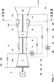
- Fig. 1 shows a gas turbine with sequential combustion for carrying out the inventive method. It consists of a compressor 1, a first combustion chamber 4, a first turbine 7, a second combustion chamber 15 and a second turbine 12. Typically, it comprises a generator 19, which at the cold end of the gas turbine, that is the compressor 1 to a shaft 18th the gas turbine is coupled.
- a fuel, gas or oil is introduced via a fuel supply 5 into the first combustion chamber 4, mixed with air compressed in the compressor 1 and burned.
- the hot gases 6 are partially released under work delivery in the following first turbine 7.
- the partially expanded gases 8 in burners 9 of the second combustion chamber 15 are admixed with further fuel via a fuel feed 10 and combusted in the second combustion chamber 15.
- the hot gases 11 are released under work delivery in the subsequent second turbine 12.
- the exhaust gases 13 can be beneficially supplied to a waste heat boiler of a combined cycle power plant or other waste heat utilization.
- the compressor 1 has at least one adjustable Verêtrleit réelle 14th
- an anti-icing line 26 is provided through which a part of the compressed air 3 of the intake air 2 can be supplied.
- an anti-icing control valve 25 is provided. This is conventionally switched on on cold days with high relative humidity in the ambient air to prevent the risk of icing of the compressor.
- Part of the compressed air 3 is branched off as high-pressure cooling air 22, recooled via a high-pressure cooling air cooler 35 and supplied to the first combustion chamber 4 (cooling air line not shown) and the first turbine as cooling air 22.
- the mass flow of the high-pressure cooling air 22, which is supplied to the high-pressure turbine 7, can be controlled in the example by a high-pressure cooling air control valve 21.
- a part of the high-pressure cooling air 22 is fed as so-called carrier air 24 into the burner lances of the burners 9 of the second combustion chamber 15.
- the mass flow of the carrier air 24 can be regulated by a carrier air control valve 17.
- cooling air 23 From the compressor 1, a part of the air is branched partially compressed, recooled via a low-pressure cooling air cooler 36 and the second combustion chamber 15 and the second turbine as the cooling air 23 is supplied.
- the mass flow of the cooling air 23 can be controlled in the example by a cooling air control valve 16.
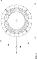
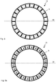
- the combustion chambers are designed, for example, as annular combustion chambers with a multiplicity of individual burners 9, as shown in FIG Fig. 2 and 3 the example of the second combustion chamber 15 is shown. Each of these burners 9 is supplied with fuel via a fuel distribution system and fuel supply 10.
- Fig. 2 a section through the second combustion chamber 15 with burners 9 of a gas turbine with sequential combustion and the fuel distribution system with a fuel ring line 30 and eight individual switching valves 37 to turn off eight burners 9.
- individual switching valves 37 By closing of individual switching valves 37, the fuel supply to individual burners 9 is stopped and this on the distributed remaining burner, wherein the total fuel mass flow is controlled by a control valve 28. This reduces the air ratio ⁇ of the burners 9 in operation.
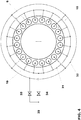
- Fig. 3 shows a section through the second combustion chamber 15 and a fuel distribution system with a fuel ring line 30 and fuel supply lines 10 to the individual burners 9.
- four burners 9 are provided with individual control valves 27 for controlling the fuel flow in the fuel supply lines 10 of the respective burner 9.
- the total fuel mass flow is controlled via a control valve 28.
- the separate control of the fuel mass flow to the four burners 9 with individual control valve 27 allows staging.
- the four individual control valves are fully open at low part load, thus in all the burner 9 of the second combustion chamber 15th uniformly introduced fuel, so that all burners 9 are operated to minimize the CO emissions with the same air ratio ⁇ .
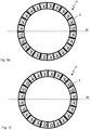
- Fig. 4 shows a section through the second combustion chamber 15 of a gas turbine with sequential combustion and the fuel distribution system with two separately controllable subset of burners. These each have a fuel ring line for a first subgroup 31 and a fuel ring line for a second subgroup 32 and the associated fuel feeds 10.
- a fuel regulating valve for the first subgroup 33 and a fuel regulating valve for the second subgroup 34 are provided.
- the two control valves for the first and the second subgroup 33, 34 are controlled at low partial load so that the fuel mass flow per burner is the same.
- control valve of the first subgroup 33 can be connected downstream of the second control valve 34.
- the control valve of the first subgroup 33 at part load the control valve of the first subgroup 33 to open completely and throttled at high part load, then to realize a staging.
- the total fuel mass flow is then controlled via the control valve 34.
- the fuel being a liquid fuel, such as oil, depending on the type of burner, water injection will be required to reduce NOx emissions.
- the example Fuel supply and it must be provided appropriate lines and control systems.
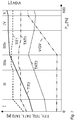
- Fig. 5 shows a conventional method for controlling a gas turbine with sequential combustion.
- the gas turbine is loaded to full load, ie a relative load P rel of 100%.
- 0% P rel the adjustable compressor guide is closed, that is to say to a minimum opening angle is set.
- the first combustion chamber is ignited, resulting in a turbine inlet temperature TIT1 of the first turbine 7 and a corresponding turbine outlet temperature TAT1.
- the second combustion chamber is not yet in operation, so that no heating of the gases takes place in the second combustion chamber.
- the temperature TAT1 of the gases leaving the first turbine 7 is reduced to the turbine inlet temperature TIT2 of the second turbine 12 by the combustion chamber cooling and consideration of the low-pressure turbine cooling. From the second turbine 12, the expanded gases exit at a temperature TAT2.
- phase I of the method starting from 0% P rel for increasing the power, first the TIT1 is raised up to a TIT1 limit. As the TIT1 increases, the exit temperature TAT1 and the temperatures TIT2 and TAT2 of the subsequent second turbine 12 also increase.
- the second combustion chamber 15 is ignited at the beginning of phase II and the fuel supply 10 is increased in the burner 9 of the second combustion chamber in proportion to the load.
- the TIT2 and TAT2 increase via load in the phase II correspondingly with a steep gradient until a first limit of TAT2 is reached.
- the TAT2 limit is identical to a TAT2 full load limit.
- the adjustable compressor guide 14 is opened to regulate the power by increasing the Ansaugmassenstroms. Proportional to the Ansaugmassenstrom increases the pressure ratio of the second turbine 12, which is why at constant TAT2 the TIT2 on the relative power P rel continues to increase until a first TIT2 limit is reached.
- the adjustable compressor guide row 14 is opened further at a constant TIT2 until it reaches the maximum open position.
- the TIT2 is raised from the first TIT2 limit to a second TIT2 limit at a constant position of the variable compressor guide row 14 until 100% P rel is reached.
- Fig. 6 shows a method for controlling a gas turbine with sequential combustion, in which, compared to the method shown in Figure 5, the phase II has been modified.
- Phase II is divided into two parts here.
- the load is increased in a phase IIa by opening the adjustable Verêtrleit réelle 14.
- the second combustion chamber 15 is not in operation during phase IIa.
- the adjustable Verêtrleit réelle 14 has reached the open position at the end of phase IIa, the second combustion chamber 15 is switched on and the adjustable Verêtrleit réelle 14 quickly closed.
- the fuel mass flow introduced into the second combustion chamber 15 is increased.
- the second combustion chamber is operated only at significantly higher load with significantly increased fuel mass flow and significantly increased TIT2 stationary. Since the Ansaugmassenstrom, as soon as the second combustion chamber is stationary in operation, unchanged, the minimum flow, the air ratio ⁇ is significantly reduced and thus reduces CO emissions. In Phase IIb, the line is raised by increasing TIT2 until the TAT2 limit is reached, analogous to the procedure described for Phase II. During the rapid closure of the adjustable Verêtrleitsch 14 may lead to increased CO emissions, which is why they are fed with the highest possible angular velocity.
- the angular velocity is on the one hand by the limit the actuators of the adjustable Ver Whyrleitology 14 limited on the other hand it can come to too fast closure to load fluctuations and problems in the control of the turbine inlet temperatures. Even if the actuators allow closing of the adjustable Ver Whyrleit réelle 14 within a few seconds, the adjustable Ver Whyrleitology 14 is closed, for example, in a time interval of a few minutes, preferably in an interval of less than half a minute.
- Fig. 7 shows a method for controlling a gas turbine with sequential combustion, in which, compared to the method shown in Figure 5, the phase III has been modified. In the FIG. 7 Two modifications are shown.
- the first phase III modification is to raise the TAT2 limit to a second limit higher than the TAT2 full load limit. This allows a further increase in TIT2 until the second TAT2 limit is reached.
- the adjustable Verêtrleit réelle 14 remains closed until the end of phase IIIa.
- the TAT2 limit is reduced in proportion to the load until the first TAT2 limit is reached at the end of the phase.
- the adjustable compressor guide 14 is opened with a steep gradient.
- the second in Fig. 7 The modification shown is an increase of TIT1 and TAT1 at the beginning of phase IIIa.
- the increase shown is shown only as an example during Phase III. It is independent of the cornerstones of the process or phases. It can be carried out in any CO emission-critical partial load range.
- the air ratio ⁇ is not directly influenced here.
- the minimum air ratio ⁇ min for achieving low-emission combustion depends on the boundary conditions of the combustion.
- Increasing TAT1 improves these constraints. Lifting the TAT1 increases the Temperature and reaction rate in the second combustion chamber 15, whereby the burn-out is improved and the CO emissions are reduced.
- Fig. 8 shows a schematic cross section through the second combustion chamber 15 of a gas turbine with sequential combustion, in which all the burners 9 are in operation. They are each marked with an x as in operation.
- Fig. 8a shows a cross section through the second combustion chamber 15 of a gas turbine with sequential combustion, in the left and right depending on the parting plane 38 adjacent burner 9 are turned off and the remaining burners 9 are in operation.
- the off burners 9 are marked with an o as not in operation.
- Fig. 8b shows a cross section through the second combustion chamber 15 of a gas turbine with sequential combustion in the left and right two each adjacent to the dividing plane 38 burner 9 are turned off and the other burners 9 are in operation.
- Fig. 8a and 8b For switching the single burner in Fig. 8a and 8b
- individual switching valves are provided in the fuel supply lines 10 to the individual burners 9.
- all burners 9 are in operation at high relative load P rel .
- P rel When lowering the load below a limit of P rel are initially corresponding Fig. 8a the adjacent to the parting plane 38 burner 9 is turned off.
- Fig. 8b also turned off the burners 9, which are two positions away from the dividing plane 38.
- Fig. 9a shows a cross-section through the second combustion chamber 15 of a gas turbine with sequential combustion, in the right is adjacent to the parting plane 38 burner 9 is turned off and the remaining burners 9 are in operation,
- Fig. 9b shows a cross section through the second combustion chamber 15 of a gas turbine with sequential combustion, in the left and right each one of the Separating plane 38 adjacent burner 9 is turned off and the remaining burners 9 are in operation,
- shutdown of burner subgroups can be turned off starting from high load, in which all the burners 9 are in operation, even individual burners 9.
- Fig. 9a shown only one lying on the left in the direction of the dividing plane 38 adjacent burner 9 off.
- a burner 9 which lies in the direction of view to the right and adjoins the separating plane 38 is switched off.
- burners 9 can be switched off.
- Fig. 10 shows a cross section through the second combustion chamber 15 of a gas turbine with sequential combustion, in which three groups of burners 9 are turned off and the remaining burners 9 are in operation.
- Such a configuration can be selected, for example, if the influence of the leaks at the parting line 38 on the CO emissions is small and, in addition, the influence of switched off, cold neighboring burners on the CO emissions of the turned-on burners 9 is small.
- Advantage of this arrangement is a relatively homogeneous temperature profile at the outlet of the combustion chamber 15th
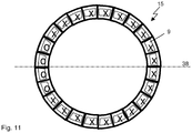
- Fig. 11 shows a cross section through the second combustion chamber 15 of a gas turbine with sequential combustion, in which only one group of burners 9 is turned off and the remaining burners 9 are in operation.
- This arrangement is advantageous if the influence of switched off, cold neighbor burner on the CO emissions of the switched-burner 9 is very large and the resulting poor outlet temperature profile of the combustion chamber 15 can be tolerated by the subsequent second turbine 12 or adapted the cooling to the temperature profile can be.
Landscapes
- Engineering & Computer Science (AREA)
- Chemical & Material Sciences (AREA)
- Combustion & Propulsion (AREA)
- Mechanical Engineering (AREA)
- General Engineering & Computer Science (AREA)
- Control Of Turbines (AREA)
- Turbine Rotor Nozzle Sealing (AREA)
Applications Claiming Priority (2)
| Application Number | Priority Date | Filing Date | Title |
|---|---|---|---|
| CH00536/09A CH700796A1 (de) | 2009-04-01 | 2009-04-01 | Verfahren zum CO-emissionsarmen Betrieb einer Gasturbine mit sequentieller Verbrennung und Gasturbine mit verbessertem Teillast- Emissionsverhalten. |
| PCT/EP2010/053171 WO2010112318A1 (de) | 2009-04-01 | 2010-03-12 | Gasturbine mit verbessertem teillast-emissionsverhalten |
Publications (2)
| Publication Number | Publication Date |
|---|---|
| EP2414653A1 EP2414653A1 (de) | 2012-02-08 |
| EP2414653B1 true EP2414653B1 (de) | 2017-03-01 |
Family
ID=40848719
Family Applications (1)
| Application Number | Title | Priority Date | Filing Date |
|---|---|---|---|
| EP10709482.3A Not-in-force EP2414653B1 (de) | 2009-04-01 | 2010-03-12 | Gasturbine mit verbessertem teillast-emissionsverhalten |
Country Status (7)
| Country | Link |
|---|---|
| US (2) | US8434312B2 (ja) |
| EP (1) | EP2414653B1 (ja) |
| JP (1) | JP5680053B2 (ja) |
| CH (1) | CH700796A1 (ja) |
| ES (1) | ES2627679T3 (ja) |
| RU (1) | RU2562681C2 (ja) |
| WO (1) | WO2010112318A1 (ja) |
Families Citing this family (39)
| Publication number | Priority date | Publication date | Assignee | Title |
|---|---|---|---|---|
| CH700796A1 (de) | 2009-04-01 | 2010-10-15 | Alstom Technology Ltd | Verfahren zum CO-emissionsarmen Betrieb einer Gasturbine mit sequentieller Verbrennung und Gasturbine mit verbessertem Teillast- Emissionsverhalten. |
| WO2012052276A1 (en) | 2010-10-19 | 2012-04-26 | Alstom Technology Ltd | Method for operation of a combined-cycle power plant with cogeneration, and a combined-cycle power plant for carrying out the method |
| WO2012052277A1 (en) * | 2010-10-19 | 2012-04-26 | Alstom Technology Ltd | Method for operating a combined-cycle power plant with cogeneration and a combined-cycle power plant for carrying out the method |
| CH704829A2 (de) * | 2011-04-08 | 2012-11-15 | Alstom Technology Ltd | Gasturbogruppe und zugehöriges Betriebsverfahren. |
| WO2014001230A1 (en) | 2012-06-29 | 2014-01-03 | Alstom Technology Ltd | Method for a part load co reduction operation for a sequential gas turbine |
| RU2561956C2 (ru) | 2012-07-09 | 2015-09-10 | Альстом Текнолоджи Лтд | Газотурбинная система сгорания |
| RU2563445C2 (ru) * | 2012-07-13 | 2015-09-20 | Альстом Текнолоджи Лтд | Способ и устройство для регулирования помпажа газотурбинного двигателя |
| AU2013219140B2 (en) * | 2012-08-24 | 2015-10-08 | Ansaldo Energia Switzerland AG | Method for mixing a dilution air in a sequential combustion system of a gas turbine |
| EP2700879B1 (en) | 2012-08-24 | 2019-03-27 | Ansaldo Energia Switzerland AG | Method for mixing a dilution air in a sequential combustion system of a gas turbine, and sequential combustion system for a gas turbine comprising dilution air injector |
| CA2829613C (en) * | 2012-10-22 | 2016-02-23 | Alstom Technology Ltd. | Method for operating a gas turbine with sequential combustion and gas turbine for conducting said method |
| JP5899133B2 (ja) * | 2013-02-01 | 2016-04-06 | 株式会社日立製作所 | 2軸ガスタービン |
| EP2600063A3 (en) * | 2013-02-19 | 2014-05-07 | Alstom Technology Ltd | Method of operating a gas turbine with staged and/or sequential combustion |
| US10036317B2 (en) * | 2013-03-05 | 2018-07-31 | Industrial Turbine Company (Uk) Limited | Capacity control of turbine by the use of a reheat combustor in multi shaft engine |
| US9624829B2 (en) | 2013-03-05 | 2017-04-18 | Industrial Turbine Company (Uk) Limited | Cogen heat load matching through reheat and capacity match |
| EP2789915A1 (en) * | 2013-04-10 | 2014-10-15 | Alstom Technology Ltd | Method for operating a combustion chamber and combustion chamber |
| EP2829705A1 (en) * | 2013-07-24 | 2015-01-28 | Alstom Technology Ltd | Gas turbine and method of controlling gas turbine |
| EP2835516A1 (en) | 2013-08-08 | 2015-02-11 | Alstom Technology Ltd | Gas turbine with improved part load emissions behavior |
| JP6190670B2 (ja) * | 2013-08-30 | 2017-08-30 | 三菱日立パワーシステムズ株式会社 | ガスタービン燃焼システム |
| EP2857658A1 (en) | 2013-10-01 | 2015-04-08 | Alstom Technology Ltd | Gas turbine with sequential combustion arrangement |
| RU2561754C1 (ru) * | 2014-02-12 | 2015-09-10 | Открытое акционерное общество "Газпром" | Кольцевая камера сгорания газотурбинного двигателя и способ её эксплуатации |
| US20160237904A1 (en) * | 2015-02-13 | 2016-08-18 | General Electric Company | Systems and methods for controlling an inlet air temperature of an intercooled gas turbine engine |
| EP3061944A1 (en) | 2015-02-26 | 2016-08-31 | General Electric Technology GmbH | Method for controlling the operation of a gas turbine with sequential combustion |
| US10316696B2 (en) | 2015-05-08 | 2019-06-11 | General Electric Company | System and method for improving exhaust energy recovery |
| US9957900B2 (en) | 2015-05-11 | 2018-05-01 | General Electric Company | System and method for flow control in turbine |
| US10330015B2 (en) * | 2015-09-25 | 2019-06-25 | General Electric Company | Transient emission temperature control of turbine systems |
| US10920676B2 (en) * | 2016-11-17 | 2021-02-16 | General Electric Company | Low partial load emission control for gas turbine system |
| US11092085B2 (en) * | 2017-03-14 | 2021-08-17 | General Electric Company | Method and system for controlling a sequential gas turbine engine |
| EP3376003B1 (en) * | 2017-03-14 | 2020-04-29 | General Electric Company | Method and system for controlling a sequential gas turbine engine |
| EP3421761B1 (en) * | 2017-06-30 | 2020-11-25 | Ansaldo Energia IP UK Limited | Second-stage combustor for a sequential combustor of a gas turbine |
| RU2685802C1 (ru) * | 2017-12-28 | 2019-04-23 | Игорь Анатольевич Мнушкин | Газоперекачивающий агрегат |
| EP3524799A1 (de) | 2018-02-13 | 2019-08-14 | Siemens Aktiengesellschaft | Verfahren zum betreiben einer brenneranordnung einer gasturbine |
| EP3578762A1 (en) * | 2018-06-08 | 2019-12-11 | General Electric Technology GmbH | Method for determining an outlet temperature of an upstream combustion stage in a gas turbine engine having at least two serially arranged combustion stages |
| EP3683426B1 (en) * | 2019-01-15 | 2023-05-03 | Ansaldo Energia Switzerland AG | Method for operating a gas turbine power plant and gas turbine power plant |
| JP7231493B2 (ja) * | 2019-06-12 | 2023-03-01 | 三菱重工業株式会社 | 制御装置、ガスタービン、制御方法及びプログラム |
| EP3772616B1 (en) * | 2019-08-08 | 2024-02-07 | Ansaldo Energia Switzerland AG | Method for operating a gas turbine assembly comprising a sequential combustor |
| EP3822468B1 (en) * | 2019-11-18 | 2024-04-03 | Ansaldo Energia Switzerland AG | Gas turbine engine operable at very low partial load and method of controlling a gas turbine engine |
| US11203986B1 (en) * | 2020-06-08 | 2021-12-21 | General Electric Company | Systems and methods for extended emissions compliant operation of a gas turbine engine |
| CN112627989A (zh) * | 2021-01-08 | 2021-04-09 | 大连欧谱纳透平动力科技有限公司 | 控制小型燃气轮机排气温度和氮氧化物浓度的系统及方法 |
| EP4206452A1 (en) * | 2021-12-30 | 2023-07-05 | Ansaldo Energia Switzerland AG | Method for operating a gas turbine assembly for a power plant and gas turbine assembly for a power plant |
Citations (1)
| Publication number | Priority date | Publication date | Assignee | Title |
|---|---|---|---|---|
| EP1319895A2 (de) * | 2001-12-12 | 2003-06-18 | Rolls-Royce Deutschland Ltd & Co KG | Magervormischbrenner für eine Gasturbine sowie Verfahren zum Betrieb eines Magervormischbrenners |
Family Cites Families (16)
| Publication number | Priority date | Publication date | Assignee | Title |
|---|---|---|---|---|
| US5226287A (en) | 1991-07-19 | 1993-07-13 | General Electric Company | Compressor stall recovery apparatus |
| JP3131805B2 (ja) * | 1992-06-16 | 2001-02-05 | 三井造船株式会社 | ガスタービン用燃焼器における燃料分配制御装置 |
| JPH06213456A (ja) * | 1993-01-13 | 1994-08-02 | Mitsui Eng & Shipbuild Co Ltd | ガスタービン用燃焼器とその燃料制御装置 |
| DE59309644D1 (de) * | 1993-09-06 | 1999-07-15 | Asea Brown Boveri | Verfahren zur Erstellung eines Teillastbetriebes bei einer Gasturbogruppe |
| EP0646704B1 (de) * | 1993-09-06 | 1997-11-26 | Asea Brown Boveri Ag | Verfahren zur Regelung einer mit zwei Brennkammern bestückten Gasturbogruppe |
| DE4446610A1 (de) * | 1994-12-24 | 1996-06-27 | Abb Management Ag | Verfahren zum Betrieb einer Gasturbogruppe |
| RU2186232C2 (ru) * | 1997-05-06 | 2002-07-27 | Особов Виктор Исаакович | Способ работы газотурбинной установки |
| EP0921292B1 (de) * | 1997-12-08 | 2003-09-10 | ALSTOM (Switzerland) Ltd | Verfahren zur Regelung einer Gasturbogruppe |
| DE59811336D1 (de) * | 1998-07-22 | 2004-06-09 | Alstom Technology Ltd Baden | Verfahren zum Betrieb einer Gasturbinenbrennkammer mit flüssigem Brennstoff |
| JP2002295831A (ja) * | 2001-03-30 | 2002-10-09 | Mitsubishi Heavy Ind Ltd | ガスタービン燃焼器の燃焼制御システム |
| EP1531305A1 (en) * | 2003-11-12 | 2005-05-18 | United Technologies Corporation | Multi-point fuel injector |
| JP4015656B2 (ja) * | 2004-11-17 | 2007-11-28 | 三菱重工業株式会社 | ガスタービン燃焼器 |
| JP4486549B2 (ja) * | 2005-06-06 | 2010-06-23 | 三菱重工業株式会社 | ガスタービンの燃焼器 |
| US7565805B2 (en) * | 2005-11-22 | 2009-07-28 | General Electric Company | Method for operating gas turbine engine systems |
| WO2010000020A1 (en) | 2008-06-30 | 2010-01-07 | Cathrx Ltd | A catheter |
| CH700796A1 (de) * | 2009-04-01 | 2010-10-15 | Alstom Technology Ltd | Verfahren zum CO-emissionsarmen Betrieb einer Gasturbine mit sequentieller Verbrennung und Gasturbine mit verbessertem Teillast- Emissionsverhalten. |
-
2009
- 2009-04-01 CH CH00536/09A patent/CH700796A1/de not_active Application Discontinuation
-
2010
- 2010-03-12 JP JP2012502550A patent/JP5680053B2/ja not_active Expired - Fee Related
- 2010-03-12 WO PCT/EP2010/053171 patent/WO2010112318A1/de active Application Filing
- 2010-03-12 ES ES10709482.3T patent/ES2627679T3/es active Active
- 2010-03-12 RU RU2011144106/06A patent/RU2562681C2/ru not_active IP Right Cessation
- 2010-03-12 EP EP10709482.3A patent/EP2414653B1/de not_active Not-in-force
-
2011
- 2011-09-23 US US13/241,983 patent/US8434312B2/en not_active Expired - Fee Related
-
2013
- 2013-04-03 US US13/855,857 patent/US8794008B2/en not_active Expired - Fee Related
Patent Citations (1)
| Publication number | Priority date | Publication date | Assignee | Title |
|---|---|---|---|---|
| EP1319895A2 (de) * | 2001-12-12 | 2003-06-18 | Rolls-Royce Deutschland Ltd & Co KG | Magervormischbrenner für eine Gasturbine sowie Verfahren zum Betrieb eines Magervormischbrenners |
Also Published As
| Publication number | Publication date |
|---|---|
| US8434312B2 (en) | 2013-05-07 |
| ES2627679T3 (es) | 2017-07-31 |
| WO2010112318A1 (de) | 2010-10-07 |
| US8794008B2 (en) | 2014-08-05 |
| EP2414653A1 (de) | 2012-02-08 |
| US20130219904A1 (en) | 2013-08-29 |
| US20120017601A1 (en) | 2012-01-26 |
| RU2011144106A (ru) | 2013-05-10 |
| CH700796A1 (de) | 2010-10-15 |
| JP2012522922A (ja) | 2012-09-27 |
| RU2562681C2 (ru) | 2015-09-10 |
| JP5680053B2 (ja) | 2015-03-04 |
Similar Documents
| Publication | Publication Date | Title |
|---|---|---|
| EP2414653B1 (de) | Gasturbine mit verbessertem teillast-emissionsverhalten | |
| EP2562369B1 (de) | Verfahren zum Betrieb einer Gasturbinenanlage sowie Gasturbinenanlage zur Durchführung des Verfahrens | |
| EP2831394B1 (de) | Gasturbine mit regelbarem kühlluftsystem | |
| EP2473726B1 (de) | Gasturbogruppe | |
| EP0718470B1 (de) | Verfahren zum Betrieb einer Gasturbogruppe | |
| DE102009043864B4 (de) | Kanalbrenner für heizwertarmen Brennstoff für Heizsysteme und Wärmerückgewinnungssysteme | |
| DE112013005578B4 (de) | Energieerzeugungssystem, Antriebsverfahren für Energieerzeugungssystem | |
| DE102008002941A1 (de) | Wobbe Steuerung und verbesserte Bedienbarkeit durch In-Linie Treibstoffumwandlung | |
| CH704829A2 (de) | Gasturbogruppe und zugehöriges Betriebsverfahren. | |
| CH703218A1 (de) | Verfahren zum Betreiben eines Gas-und-Dampf-Kombikraftwerk mit Rauchgasrezirkulation sowie Kraftwerk. | |
| CH708571A2 (de) | Gasturbinensystem und Verfahren zur Steuerung der Brennstoffverteilung in den Brennkammern einer Gasturbine. | |
| DE19952885A1 (de) | Verfahren und Betrieb einer Kraftwerksanlage | |
| CH704381A1 (de) | Verfahren zum Betrieb eines Gasturbinenkraftwerks mit Abgasrezirkulation sowie Gasturbinenkraftwerk mit Abgasrezirkulation. | |
| EP2578839A1 (de) | Verfahren zum Betrieb eines Gasturbinenkraftwerks mit Abgasrezirkulation und entsprechendes Gasturbinenkraftwerk | |
| DE112012002336T5 (de) | Wärmerückgewinnungdampferzeuger und Kraftwerk | |
| EP3105435B1 (de) | Verfahren und anordnung zum betrieben einer gasturbinenainlage im teillastbetrieb | |
| EP2071156B1 (de) | Brennstoffverteilungssystem für eine Gasturbine mit mehrstufiger Brenneranordnung | |
| CH708180B1 (de) | Gasturbinenmotor mit zwei Brennkammern und einem Umleitungskanal. | |
| DE60132922T2 (de) | Verfahren und vorrichtung zur versorgung einer brennkammer mit brennstoff | |
| EP0474894B1 (de) | Gasturbinenanordnung | |
| EP3698031B1 (de) | Verfahren zum betreiben einer brenneranordnung, bevorzugterweise einer gasturbine | |
| EP1662202B1 (de) | Brenner für eine Gasturbinenanlage | |
| DE102006059532B4 (de) | Verfahren zum Betreiben einer Gasturbinenanordnung mit sequentieller Verbrennung | |
| EP0740057B1 (de) | Verfahren zum Starten einer sequentiell befeuerten Gasturbogruppe | |
| DE102008053755A1 (de) | Register Pilotbrennersystem für Gasturbinen |
Legal Events
| Date | Code | Title | Description |
|---|---|---|---|
| PUAI | Public reference made under article 153(3) epc to a published international application that has entered the european phase |
Free format text: ORIGINAL CODE: 0009012 |
|
| 17P | Request for examination filed |
Effective date: 20110920 |
|
| AK | Designated contracting states |
Kind code of ref document: A1 Designated state(s): AT BE BG CH CY CZ DE DK EE ES FI FR GB GR HR HU IE IS IT LI LT LU LV MC MK MT NL NO PL PT RO SE SI SK SM TR |
|
| DAX | Request for extension of the european patent (deleted) | ||
| REG | Reference to a national code |
Ref country code: DE Ref legal event code: R079 Ref document number: 502010013238 Country of ref document: DE Free format text: PREVIOUS MAIN CLASS: F02C0006000000 Ipc: F02C0009260000 |
|
| RIC1 | Information provided on ipc code assigned before grant |
Ipc: F23R 7/00 20060101ALI20131011BHEP Ipc: F23C 6/04 20060101ALI20131011BHEP Ipc: F02C 9/26 20060101AFI20131011BHEP Ipc: F02C 6/00 20060101ALI20131011BHEP Ipc: F23N 1/02 20060101ALI20131011BHEP |
|
| 17Q | First examination report despatched |
Effective date: 20140131 |
|
| RAP1 | Party data changed (applicant data changed or rights of an application transferred) |
Owner name: GENERAL ELECTRIC TECHNOLOGY GMBH |
|
| GRAP | Despatch of communication of intention to grant a patent |
Free format text: ORIGINAL CODE: EPIDOSNIGR1 |
|
| INTG | Intention to grant announced |
Effective date: 20160921 |
|
| GRAS | Grant fee paid |
Free format text: ORIGINAL CODE: EPIDOSNIGR3 |
|
| GRAA | (expected) grant |
Free format text: ORIGINAL CODE: 0009210 |
|
| AK | Designated contracting states |
Kind code of ref document: B1 Designated state(s): AT BE BG CH CY CZ DE DK EE ES FI FR GB GR HR HU IE IS IT LI LT LU LV MC MK MT NL NO PL PT RO SE SI SK SM TR |
|
| REG | Reference to a national code |
Ref country code: GB Ref legal event code: FG4D Free format text: NOT ENGLISH |
|
| REG | Reference to a national code |
Ref country code: CH Ref legal event code: EP Ref country code: AT Ref legal event code: REF Ref document number: 871663 Country of ref document: AT Kind code of ref document: T Effective date: 20170315 |
|
| REG | Reference to a national code |
Ref country code: IE Ref legal event code: FG4D Free format text: LANGUAGE OF EP DOCUMENT: GERMAN |
|
| REG | Reference to a national code |
Ref country code: DE Ref legal event code: R096 Ref document number: 502010013238 Country of ref document: DE |
|
| PGFP | Annual fee paid to national office [announced via postgrant information from national office to epo] |
Ref country code: DE Payment date: 20170322 Year of fee payment: 8 |
|
| RAP2 | Party data changed (patent owner data changed or rights of a patent transferred) |
Owner name: ANSALDO ENERGIA IP UK LIMITED |
|
| PGFP | Annual fee paid to national office [announced via postgrant information from national office to epo] |
Ref country code: ES Payment date: 20170315 Year of fee payment: 8 |
|
| REG | Reference to a national code |
Ref country code: NL Ref legal event code: MP Effective date: 20170301 |
|
| REG | Reference to a national code |
Ref country code: LT Ref legal event code: MG4D |
|
| PG25 | Lapsed in a contracting state [announced via postgrant information from national office to epo] |
Ref country code: GR Free format text: LAPSE BECAUSE OF FAILURE TO SUBMIT A TRANSLATION OF THE DESCRIPTION OR TO PAY THE FEE WITHIN THE PRESCRIBED TIME-LIMIT Effective date: 20170602 Ref country code: FI Free format text: LAPSE BECAUSE OF FAILURE TO SUBMIT A TRANSLATION OF THE DESCRIPTION OR TO PAY THE FEE WITHIN THE PRESCRIBED TIME-LIMIT Effective date: 20170301 Ref country code: NO Free format text: LAPSE BECAUSE OF FAILURE TO SUBMIT A TRANSLATION OF THE DESCRIPTION OR TO PAY THE FEE WITHIN THE PRESCRIBED TIME-LIMIT Effective date: 20170601 Ref country code: LT Free format text: LAPSE BECAUSE OF FAILURE TO SUBMIT A TRANSLATION OF THE DESCRIPTION OR TO PAY THE FEE WITHIN THE PRESCRIBED TIME-LIMIT Effective date: 20170301 Ref country code: HR Free format text: LAPSE BECAUSE OF FAILURE TO SUBMIT A TRANSLATION OF THE DESCRIPTION OR TO PAY THE FEE WITHIN THE PRESCRIBED TIME-LIMIT Effective date: 20170301 |
|
| PGFP | Annual fee paid to national office [announced via postgrant information from national office to epo] |
Ref country code: GB Payment date: 20170419 Year of fee payment: 8 |
|
| REG | Reference to a national code |
Ref country code: ES Ref legal event code: FG2A Ref document number: 2627679 Country of ref document: ES Kind code of ref document: T3 Effective date: 20170731 |
|
| PG25 | Lapsed in a contracting state [announced via postgrant information from national office to epo] |
Ref country code: LV Free format text: LAPSE BECAUSE OF FAILURE TO SUBMIT A TRANSLATION OF THE DESCRIPTION OR TO PAY THE FEE WITHIN THE PRESCRIBED TIME-LIMIT Effective date: 20170301 Ref country code: SE Free format text: LAPSE BECAUSE OF FAILURE TO SUBMIT A TRANSLATION OF THE DESCRIPTION OR TO PAY THE FEE WITHIN THE PRESCRIBED TIME-LIMIT Effective date: 20170301 Ref country code: BG Free format text: LAPSE BECAUSE OF FAILURE TO SUBMIT A TRANSLATION OF THE DESCRIPTION OR TO PAY THE FEE WITHIN THE PRESCRIBED TIME-LIMIT Effective date: 20170601 |
|
| PG25 | Lapsed in a contracting state [announced via postgrant information from national office to epo] |
Ref country code: NL Free format text: LAPSE BECAUSE OF FAILURE TO SUBMIT A TRANSLATION OF THE DESCRIPTION OR TO PAY THE FEE WITHIN THE PRESCRIBED TIME-LIMIT Effective date: 20170301 |
|
| PG25 | Lapsed in a contracting state [announced via postgrant information from national office to epo] |
Ref country code: RO Free format text: LAPSE BECAUSE OF FAILURE TO SUBMIT A TRANSLATION OF THE DESCRIPTION OR TO PAY THE FEE WITHIN THE PRESCRIBED TIME-LIMIT Effective date: 20170301 Ref country code: CZ Free format text: LAPSE BECAUSE OF FAILURE TO SUBMIT A TRANSLATION OF THE DESCRIPTION OR TO PAY THE FEE WITHIN THE PRESCRIBED TIME-LIMIT Effective date: 20170301 Ref country code: EE Free format text: LAPSE BECAUSE OF FAILURE TO SUBMIT A TRANSLATION OF THE DESCRIPTION OR TO PAY THE FEE WITHIN THE PRESCRIBED TIME-LIMIT Effective date: 20170301 Ref country code: SK Free format text: LAPSE BECAUSE OF FAILURE TO SUBMIT A TRANSLATION OF THE DESCRIPTION OR TO PAY THE FEE WITHIN THE PRESCRIBED TIME-LIMIT Effective date: 20170301 |
|
| PGFP | Annual fee paid to national office [announced via postgrant information from national office to epo] |
Ref country code: IT Payment date: 20170630 Year of fee payment: 8 |
|
| REG | Reference to a national code |
Ref country code: CH Ref legal event code: PL |
|
| PG25 | Lapsed in a contracting state [announced via postgrant information from national office to epo] |
Ref country code: IS Free format text: LAPSE BECAUSE OF FAILURE TO SUBMIT A TRANSLATION OF THE DESCRIPTION OR TO PAY THE FEE WITHIN THE PRESCRIBED TIME-LIMIT Effective date: 20170701 Ref country code: PT Free format text: LAPSE BECAUSE OF FAILURE TO SUBMIT A TRANSLATION OF THE DESCRIPTION OR TO PAY THE FEE WITHIN THE PRESCRIBED TIME-LIMIT Effective date: 20170703 Ref country code: SM Free format text: LAPSE BECAUSE OF FAILURE TO SUBMIT A TRANSLATION OF THE DESCRIPTION OR TO PAY THE FEE WITHIN THE PRESCRIBED TIME-LIMIT Effective date: 20170301 Ref country code: PL Free format text: LAPSE BECAUSE OF FAILURE TO SUBMIT A TRANSLATION OF THE DESCRIPTION OR TO PAY THE FEE WITHIN THE PRESCRIBED TIME-LIMIT Effective date: 20170301 |
|
| REG | Reference to a national code |
Ref country code: DE Ref legal event code: R097 Ref document number: 502010013238 Country of ref document: DE |
|
| REG | Reference to a national code |
Ref country code: IE Ref legal event code: MM4A |
|
| PLBE | No opposition filed within time limit |
Free format text: ORIGINAL CODE: 0009261 |
|
| STAA | Information on the status of an ep patent application or granted ep patent |
Free format text: STATUS: NO OPPOSITION FILED WITHIN TIME LIMIT |
|
| REG | Reference to a national code |
Ref country code: FR Ref legal event code: ST Effective date: 20171228 |
|
| PG25 | Lapsed in a contracting state [announced via postgrant information from national office to epo] |
Ref country code: MC Free format text: LAPSE BECAUSE OF FAILURE TO SUBMIT A TRANSLATION OF THE DESCRIPTION OR TO PAY THE FEE WITHIN THE PRESCRIBED TIME-LIMIT Effective date: 20170301 Ref country code: LU Free format text: LAPSE BECAUSE OF NON-PAYMENT OF DUE FEES Effective date: 20170312 Ref country code: DK Free format text: LAPSE BECAUSE OF FAILURE TO SUBMIT A TRANSLATION OF THE DESCRIPTION OR TO PAY THE FEE WITHIN THE PRESCRIBED TIME-LIMIT Effective date: 20170301 Ref country code: FR Free format text: LAPSE BECAUSE OF NON-PAYMENT OF DUE FEES Effective date: 20170502 |
|
| 26N | No opposition filed |
Effective date: 20171204 |
|
| PG25 | Lapsed in a contracting state [announced via postgrant information from national office to epo] |
Ref country code: IE Free format text: LAPSE BECAUSE OF NON-PAYMENT OF DUE FEES Effective date: 20170312 Ref country code: LI Free format text: LAPSE BECAUSE OF NON-PAYMENT OF DUE FEES Effective date: 20170331 Ref country code: CH Free format text: LAPSE BECAUSE OF NON-PAYMENT OF DUE FEES Effective date: 20170331 Ref country code: SI Free format text: LAPSE BECAUSE OF FAILURE TO SUBMIT A TRANSLATION OF THE DESCRIPTION OR TO PAY THE FEE WITHIN THE PRESCRIBED TIME-LIMIT Effective date: 20170301 |
|
| REG | Reference to a national code |
Ref country code: BE Ref legal event code: MM Effective date: 20170331 |
|
| REG | Reference to a national code |
Ref country code: AT Ref legal event code: MM01 Ref document number: 871663 Country of ref document: AT Kind code of ref document: T Effective date: 20170312 |
|
| PG25 | Lapsed in a contracting state [announced via postgrant information from national office to epo] |
Ref country code: BE Free format text: LAPSE BECAUSE OF NON-PAYMENT OF DUE FEES Effective date: 20170331 |
|
| PG25 | Lapsed in a contracting state [announced via postgrant information from national office to epo] |
Ref country code: AT Free format text: LAPSE BECAUSE OF NON-PAYMENT OF DUE FEES Effective date: 20170312 |
|
| PG25 | Lapsed in a contracting state [announced via postgrant information from national office to epo] |
Ref country code: MT Free format text: LAPSE BECAUSE OF FAILURE TO SUBMIT A TRANSLATION OF THE DESCRIPTION OR TO PAY THE FEE WITHIN THE PRESCRIBED TIME-LIMIT Effective date: 20170301 |
|
| REG | Reference to a national code |
Ref country code: DE Ref legal event code: R119 Ref document number: 502010013238 Country of ref document: DE |
|
| GBPC | Gb: european patent ceased through non-payment of renewal fee |
Effective date: 20180312 |
|
| PG25 | Lapsed in a contracting state [announced via postgrant information from national office to epo] |
Ref country code: DE Free format text: LAPSE BECAUSE OF NON-PAYMENT OF DUE FEES Effective date: 20181002 |
|
| PG25 | Lapsed in a contracting state [announced via postgrant information from national office to epo] |
Ref country code: GB Free format text: LAPSE BECAUSE OF NON-PAYMENT OF DUE FEES Effective date: 20180312 Ref country code: IT Free format text: LAPSE BECAUSE OF NON-PAYMENT OF DUE FEES Effective date: 20180312 |
|
| PG25 | Lapsed in a contracting state [announced via postgrant information from national office to epo] |
Ref country code: HU Free format text: LAPSE BECAUSE OF FAILURE TO SUBMIT A TRANSLATION OF THE DESCRIPTION OR TO PAY THE FEE WITHIN THE PRESCRIBED TIME-LIMIT; INVALID AB INITIO Effective date: 20100312 |
|
| REG | Reference to a national code |
Ref country code: ES Ref legal event code: FD2A Effective date: 20190911 |
|
| PG25 | Lapsed in a contracting state [announced via postgrant information from national office to epo] |
Ref country code: CY Free format text: LAPSE BECAUSE OF NON-PAYMENT OF DUE FEES Effective date: 20170301 Ref country code: ES Free format text: LAPSE BECAUSE OF NON-PAYMENT OF DUE FEES Effective date: 20180313 |
|
| PG25 | Lapsed in a contracting state [announced via postgrant information from national office to epo] |
Ref country code: MK Free format text: LAPSE BECAUSE OF FAILURE TO SUBMIT A TRANSLATION OF THE DESCRIPTION OR TO PAY THE FEE WITHIN THE PRESCRIBED TIME-LIMIT Effective date: 20170301 |
|
| PG25 | Lapsed in a contracting state [announced via postgrant information from national office to epo] |
Ref country code: TR Free format text: LAPSE BECAUSE OF FAILURE TO SUBMIT A TRANSLATION OF THE DESCRIPTION OR TO PAY THE FEE WITHIN THE PRESCRIBED TIME-LIMIT Effective date: 20170301 |