EP2413178A1 - Zoom lens and imaging apparatus - Google Patents
Zoom lens and imaging apparatus Download PDFInfo
- Publication number
- EP2413178A1 EP2413178A1 EP11175628A EP11175628A EP2413178A1 EP 2413178 A1 EP2413178 A1 EP 2413178A1 EP 11175628 A EP11175628 A EP 11175628A EP 11175628 A EP11175628 A EP 11175628A EP 2413178 A1 EP2413178 A1 EP 2413178A1
- Authority
- EP
- European Patent Office
- Prior art keywords
- lens
- lens group
- negative
- cemented
- group
- Prior art date
- Legal status (The legal status is an assumption and is not a legal conclusion. Google has not performed a legal analysis and makes no representation as to the accuracy of the status listed.)
- Withdrawn
Links
- 238000003384 imaging method Methods 0.000 title claims description 25
- 230000003287 optical effect Effects 0.000 claims abstract description 44
- 230000005499 meniscus Effects 0.000 claims abstract description 43
- 230000008859 change Effects 0.000 claims abstract description 8
- 239000004606 Fillers/Extenders Substances 0.000 claims description 32
- 238000010276 construction Methods 0.000 claims description 13
- 229910021478 group 5 element Inorganic materials 0.000 claims description 6
- 230000004075 alteration Effects 0.000 description 56
- 238000010586 diagram Methods 0.000 description 22
- 230000000694 effects Effects 0.000 description 5
- 201000009310 astigmatism Diseases 0.000 description 4
- 239000011248 coating agent Substances 0.000 description 4
- 238000000576 coating method Methods 0.000 description 4
- 238000004519 manufacturing process Methods 0.000 description 4
- XULSCZPZVQIMFM-IPZQJPLYSA-N odevixibat Chemical compound C12=CC(SC)=C(OCC(=O)N[C@@H](C(=O)N[C@@H](CC)C(O)=O)C=3C=CC(O)=CC=3)C=C2S(=O)(=O)NC(CCCC)(CCCC)CN1C1=CC=CC=C1 XULSCZPZVQIMFM-IPZQJPLYSA-N 0.000 description 4
- 239000000463 material Substances 0.000 description 3
- 238000012544 monitoring process Methods 0.000 description 3
- 238000001228 spectrum Methods 0.000 description 3
- 230000015572 biosynthetic process Effects 0.000 description 2
- 239000011521 glass Substances 0.000 description 2
- QIVUCLWGARAQIO-OLIXTKCUSA-N (3s)-n-[(3s,5s,6r)-6-methyl-2-oxo-1-(2,2,2-trifluoroethyl)-5-(2,3,6-trifluorophenyl)piperidin-3-yl]-2-oxospiro[1h-pyrrolo[2,3-b]pyridine-3,6'-5,7-dihydrocyclopenta[b]pyridine]-3'-carboxamide Chemical compound C1([C@H]2[C@H](N(C(=O)[C@@H](NC(=O)C=3C=C4C[C@]5(CC4=NC=3)C3=CC=CN=C3NC5=O)C2)CC(F)(F)F)C)=C(F)C=CC(F)=C1F QIVUCLWGARAQIO-OLIXTKCUSA-N 0.000 description 1
- 230000009471 action Effects 0.000 description 1
- 239000006059 cover glass Substances 0.000 description 1
- 229910021480 group 4 element Inorganic materials 0.000 description 1
- 238000005286 illumination Methods 0.000 description 1
- 230000007246 mechanism Effects 0.000 description 1
- 239000000203 mixture Substances 0.000 description 1
- 238000012986 modification Methods 0.000 description 1
- 230000004048 modification Effects 0.000 description 1
- 230000009467 reduction Effects 0.000 description 1
- 230000001105 regulatory effect Effects 0.000 description 1
Images


Classifications
-
- G—PHYSICS
- G02—OPTICS
- G02B—OPTICAL ELEMENTS, SYSTEMS OR APPARATUS
- G02B27/00—Optical systems or apparatus not provided for by any of the groups G02B1/00 - G02B26/00, G02B30/00
- G02B27/64—Imaging systems using optical elements for stabilisation of the lateral and angular position of the image
- G02B27/646—Imaging systems using optical elements for stabilisation of the lateral and angular position of the image compensating for small deviations, e.g. due to vibration or shake
-
- G—PHYSICS
- G02—OPTICS
- G02B—OPTICAL ELEMENTS, SYSTEMS OR APPARATUS
- G02B15/00—Optical objectives with means for varying the magnification
- G02B15/14—Optical objectives with means for varying the magnification by axial movement of one or more lenses or groups of lenses relative to the image plane for continuously varying the equivalent focal length of the objective
- G02B15/144—Optical objectives with means for varying the magnification by axial movement of one or more lenses or groups of lenses relative to the image plane for continuously varying the equivalent focal length of the objective having four groups only
- G02B15/1441—Optical objectives with means for varying the magnification by axial movement of one or more lenses or groups of lenses relative to the image plane for continuously varying the equivalent focal length of the objective having four groups only the first group being positive
- G02B15/144113—Optical objectives with means for varying the magnification by axial movement of one or more lenses or groups of lenses relative to the image plane for continuously varying the equivalent focal length of the objective having four groups only the first group being positive arranged +-++
Definitions
- the present invention relates to a zoom lens and an imaging apparatus.
- the present invention relates to a zoom lens having a high variable magnification ratio, and which is appropriate for use in a surveillance camera for monitoring a long distance area, and to an imaging apparatus including the zoom lens.
- zoom lenses were used as optical systems for surveillance video cameras to monitor or observe long distance areas at harbors or the like.
- the zoom lenses used for such a purpose need to have high variable magnification ratios of at least 50 times and high performance. Further, such zoom lenses need to cope with wavelengths in a near-infrared region to perform photography at night or in a dense fog. Further, since the zoom lenses are high magnification optical systems, it is desirable that anti-vibration functions are provided.
- Patent Document 1 discloses a zoom lens having a variable magnification ratio of approximately 60 times.
- This lens system is composed of a positive first lens group, a negative second lens group, a positive third lens group, and a negative fourth lens group. Further, magnification is changeable by moving the second lens group and the third lens group along the optical axis of the zoom lens.
- Patent Document 2 discloses a zoom lens having a variable magnification ratio of approximately 20 times. In the lens system disclosed in Patent Document 2, aberrations, especially chromatic aberrations, are corrected in an excellent manner by appropriately setting the arrangement of refractive powers in the first lens group, Abbe numbers or the like.
- the zoom lens disclosed in Patent Document 1 achieves a high variable magnification ratio.
- correction of aberrations, especially correction of chromatic aberrations at telephoto end needs to be improved.
- the zoom lens disclosed in Patent Document 2 has high performance, but the variable magnification ratio is approximately 20 times. Therefore, a higher variable magnification ratio is desirable when the zoom lens is used to monitor a long distance area in surveillance operations at harbors or the like.
- the size of an optical system tends to become large to satisfy these requests at the same time.
- the compactness of an apparatus became strongly requested.
- a zoom lens of the present invention is a zoom lens comprising:
- ft is the focal length of the entire system at telephoto end.
- the negative meniscus lens and the positive lens are cemented together in this order from the object side of the zoom lens.
- the first lens group may consist of five lenses (in other words, the first lens group may be composed of only five lenses) that are the cemented lens composed of the negative meniscus lens and the positive lens cemented together in this order from the object side, the cemented lens composed of the negative meniscus lens and the positive lens cemented together in this order from the object side, and the positive lens, and the two cemented lenses and the positive lens being arranged in this order from the object side.
- ⁇ n > 48 and ⁇ p > 75 where ⁇ n is an average value of the Abbe numbers of all of negative lenses included in the first lens group with respect to d-line, and ⁇ p is an average value of the Abbe numbers of all of positive lenses included in the first lens group with respect to d-line.
- a most-object-side cemented lens of the cemented lenses each composed of a negative meniscus lens and a positive lens cemented together, in the first lens group is a first cemented lens, and a cemented lens located at a second position from the object side of the cemented lenses in the first lens group is a second cemented lens, the following formulas (4) and (5) are satisfied: ⁇ ⁇ 1 ⁇ 11 and ⁇ ⁇ 2 > 50 where ⁇ 1 is the absolute value of a difference between the Abbe numbers of the negative meniscus lens and the positive lens constituting the first cemented lens with respect to d-line, and ⁇ 2 is the absolute value of a difference between the Abbe numbers of the negative meniscus lens and the positive lens constituting the second cemented lens with respect to d-line.
- the fourth lens group includes a first negative lens group and a second negative lens group that is arranged on the image side of the first negative lens group.
- the first negative lens group includes a positive lens and a negative lens.
- the second negative lens group is moved in a direction perpendicular to the optical axis to compensate for a shake blur in a photography image.
- the following formula (6) is satisfied: 1.5 ⁇ f ⁇ 4 ⁇ a / f ⁇ 4 ⁇ b ⁇ 3.5 where f4a is the focal length of the first negative lens group, and f4b is the focal length of the second negative lens group.
- the second lens group in the zoom lens of the present invention may have 3-group 5-element construction in which a negative meniscus lens, a cemented lens composed of a negative lens and a positive lens cemented together in this order from the object side, and a cemented lens composed of a positive lens and a negative lens cemented together in this order from the object side are arranged in this order from the object side.
- an extender that changes the focal length of the entire system of the zoom lens toward the long focus side by being inserted into the optical path of the zoom lens may be arranged, in a removable manner, immediately on the image side of the second negative lens group in the fourth lens group.
- the term "immediately" means that no optical member is arranged between the second negative lens group and the extender.
- the term "negative meniscus lens”, the term “positive lens”, and the term “negative lens” refer to paraxial regions of lenses when the lenses are aspheric lenses.
- An imaging apparatus of the present invention includes any one of the aforementioned zoom lenses of the present invention.
- a zoom lens of the present invention includes a positive first lens group, a negative second lens group, a positive third lens group, and a positive fourth lens group, which are arranged in this order from the object side of the zoom lens. Further, the focal length of the entire system of the zoom lens is changed by moving, along the optical axis of the zoom lens, the second lens group and the third lens group in such a manner to change a distance therebetween.
- the structure of the first lens group is appropriately set, and the formula (1) is satisfied. Therefore, the zoom lens has a high variable magnification ratio and high performance, and is usable in a wide wavelength band of visible light to near-infrared light without causing the size of the lens system to become large.
- the imaging apparatus of the present invention includes a zoom lens of the present invention. Therefore, the imaging apparatus is compact, and is usable in a wide wavelength band of visible light to near-infrared light. Further, the imaging apparatus can obtain high-quality video images (images) at a high variable magnification ratio.
- Figure 1 is a cross section illustrating an example of the composition of a zoom lens according to an embodiment of the present invention.
- Figure 1 corresponds to a zoom lens in Example 1, which will be described later.
- the left side is the object side of the zoom lens
- the right side is the image side of the zoom lens.
- Figure 1 illustrates arrangement of lenses at wide angle end when the zoom lens is focused on an object at infinity.
- the zoom lens according to this embodiment includes first lens group G1 having positive refractive power, second lens group G2 having negative refractive power, third lens group G3 having positive refractive power, and fourth lens group G4 having positive refractive power, which are arranged along optical axis Z in this order from the object side of the zoom lens.
- aperture stop St and ND filter ND are arranged between the third lens group G3 and the fourth lens group G4, and the aperture stop St is fixed when the magnification of the zoom lens is changed.
- the aperture stop St illustrated in Figure 1 does not necessarily represent the size nor the shape of the aperture stop St, but a position at which the aperture stop St is located on the optical axis Z.
- the ND filter ND is not an essential element in the zoom lens of the present invention.
- the ND filter ND has a density distribution in the direction of the diameter thereof from a point on the optical axis, it is possible to reduce a fluctuation in the illumination intensity at an image plane caused by the change in magnification.
- This zoom lens can achieve a high variable magnification ratio of approximately 60 times, and is appropriate for use in a surveillance camera for monitoring a long distance area at harbors or the like.
- a cover glass, various filters or the like is arranged between the optical system and image plane Sim based on the structure of a camera on which the zoom lens is mounted.
- parallel-flat-plate-shaped optical member GC which is assumed to be such elements, is arranged between the fourth lens group G4 and the image plane Sim.
- the magnification of this zoom lens is changeable by continuously changing the focal length of the entire system of the zoom lens by moving, along the optical axis Z, the second lens group G2 and the third lens group G3 in such a manner to change a distance therebetween.
- Figure 1 schematically illustrates the paths of movement of the second lens group G2 and the third lens group G3 when magnification is changed from wide angle end to telephoto end. Arrows under the second lens group G2 and the third lens group G3 schematically indicate the paths of movements of these lens groups, respectively. Meanwhile, the first lens group G1 and the fourth lens group G3 are fixed with respect to the direction of the optical axis when magnification is changed.
- the first lens group G1 includes a cemented lens composed of lens L1 that is a negative meniscus lens and lens L2 that is a positive lens, which are cemented together in this order from the object side, a cemented lens composed of lens L3 that is a negative meniscus lens and lens L4 that is a positive lens, which are cemented together in this order from the object side, and lens L5 that is a positive lens.
- the two cemented lenses and the positive lens are arranged in this order from the object side.
- the first lens group G1 may further include a lens or lenses. However, a reduction in the size of the zoom lens is considered, it is desirable that the first lens group G1 has 3-group 5-element construction in which the aforementioned five lenses are arranged.
- the construction of the first lens group G1 including two cemented lenses, each composed of a positive lens and a negative lens, is advantageous to correction of chromatic aberrations. Further, since each lens having regulated power and shape is arranged in the aforementioned order in the first lens group G1, more flexible correction of aberrations is possible, compared with an optical system described as an example in Patent Document 1.
- the first lens group G1 may have 3-group 5-element construction in which a cemented lens composed of a negative meniscus lens having a convex surface facing the object side and a double-convex lens cemented together in this order from the object side, a cemented lens composed of a negative meniscus lens having a convex surface facing the object side and a positive meniscus lens having a convex surface facing the object side cemented together in this order from the object side, and a positive meniscus lens having a convex surface facing the object side are arranged in this order from the object side.
- This zoom lens is structured in such a manner to satisfy the following formula (1): 0.14 ⁇ fG ⁇ 1 / ft ⁇ 0.26 where fG1 is the focal length of the first lens group G1, and ft is the focal length of the entire system at telephoto end.
- the formula (1) regulates the ratio of the focal length of the first lens group G1 to the focal length of the entire system at telephoto end.
- the value of fG1/ft is lower than the lower limit defined by the formula (1), the refractive power of the first lens group G1 becomes strong. Then, negative spherical aberrations at telephoto end increase, and that is not desirable because correction of aberrations becomes difficult.
- the value of fG1/ft exceeds the upper limit defined by the formula (1), a zoom stroke for obtaining desirable magnification becomes long. Consequently, the size of the optical system becomes large, and that is not desirable.
- ⁇ n > 48 and ⁇ p > 75 where ⁇ n is an average value of the Abbe numbers of all of negative lenses included in the first lens group G1 with respect to d-line, and ⁇ p is an average value of the Abbe numbers of all of positive lenses included in the first lens group G1 with respect to d-line.
- the formula (2) regulates the Abbe numbers of the negative lenses in the first lens group G1
- the formula (3) regulates the Abbe numbers of the positive lenses in the first lens group G1.
- ⁇ 1 is the absolute value of a difference between the Abbe numbers of the negative meniscus lens and the positive lens constituting the first cemented lens with respect to d-line
- ⁇ 2 is the absolute value of a difference between the Abbe numbers of the negative meniscus lens and the positive lens constituting the second cemented lens with respect to d-line.
- the first cemented lens in the first lens group G1 corrects chromatic aberrations, and aberrations, especially spherical aberrations, at a reference wavelength on the telephoto side.
- the second cemented lens in the first lens group G1 mainly corrects chromatic aberrations on the telephoto side.
- ⁇ 1 exceeds the upper limit defined by the formula (4)
- a fluctuation amount of chromatic aberrations becomes large.
- the first cemented lens is composed of a combination of a negative meniscus lens and a positive lens made of optical materials exceeding the upper limit defined by the formula (4), it becomes difficult to correct aberrations at a reference wavelength in an excellent manner.
- the value of ⁇ 2 is lower than the lower limit defined by the formula (5), it becomes difficult to correct chromatic aberrations, especially chromatic aberrations on the telephoto side, in an excellent manner.
- the second lens group G2 may have 3-group 5-element construction in which a negative meniscus lens, a cemented lens composed of a negative lens and a positive lens cemented together in this order from the object side, and a cemented lens composed of a positive lens and a negative lens cemented together in this order from the object side are arranged in this order from the object side.
- the second lens group G2 is structured in such a manner, it is possible to correct various aberrations through the entire variable magnification range in an excellent manner, while the size of the zoom lens is reduced by using a minimum number of lenses in the second lens group G2.
- the second lens group G2 may have 3-group 5-element construction, for example, as illustrated in Figure 1 .
- lens L6 a cemented lens composed of lenses L7 and L8 cemented together in this order from the object side, and a cemented lens composed of lenses L9 and L10 cemented together in this order from the object side are arranged in this order from the object side.
- the lens L6 is a negative meniscus lens having a convex surface facing the object side.
- the lens L7 is a negative meniscus lens having a convex surface facing the object side
- the lens L8 is a positive meniscus lens having a convex surface facing the object side.
- the lens L9 is a positive meniscus lens having a convex surface facing the image side
- the lens L10 is a double-concave lens.
- the second lens group G2 which is a movable group, includes two cemented lenses, each composed of a positive lens and a negative lens, and uses many meniscus lenses. Such structure of the second lens group G2 is advantageous to correction of chromatic aberrations. Further, it is possible to correct various aberrations through the entire variable magnification range in an excellent manner.
- the third lens group G3 may have 3-group 4-element construction, for example, as illustrated in Figure 1 .
- lens L11 a cemented lens composed of lenses L12 and L13 cemented together in this order from the object side, and a lens L14 are arranged in this order from the object side.
- the lens L11 is a double-convex lens.
- the lens L12 is a negative meniscus lens having a convex surface facing the object side
- the lens L13 is a double-convex lens.
- the lens L14 is a positive meniscus lens having a convex surface facing the object side.
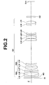
- FIG 2 is an enlarged diagram illustrating fourth lens group G4 and the vicinity thereof in the zoom lens illustrated in Figure 1 .
- the fourth lens group G4 has 8-group 11-element construction composed of lenses L15 through L25.
- the fourth lens group G4 includes first negative lens group G4a and second negative lens group G4b that is arranged on the image side of the first negative lens group G4a. Further, it is desirable that the first negative lens group G4a includes at least one positive lens and at least one negative lens, and has negative refractive power as a whole. It is desirable that the second negative lens group G4b has an anti-vibration function for compensating for a shake blur in a photography image by being moved in a direction perpendicular to optical axis Z, and that the second negative lens group G4b has negative refractive power as a whole.
- an extender is inserted into the fourth lens group G4 to increase the variable magnification ratio. Further, it is desirable that parallel rays of light enter the extender so that a larger error in the position of the extender with respect to the direction of the optical axis is allowable when the extender is inserted. Generally, the rays of light output from the third lens group G3 are convergent rays. Therefore, it is desirable that the lens group positioned between the third lens group G3 and the extender has negative refractive power as a whole.
- the first negative lens group G4a is located on the most object side in the fourth lens group G4.
- the second negative lens group G4b is located immediately on the image side of the first negative lens group G4a in the fourth lens group G4.
- the first negative lens group G4a and the second negative lens group G4b are arranged between the third lens group G3 and a position at which the extender is inserted.
- the lens group located between the third lens group G3 and the extender has negative refractive power as a whole.
- both of the first negative lens group G4a and the second negative lens group G4b in the fourth lens group G4 are negative lens groups.
- the first negative lens group G4a may have 2-group 3-element construction in which a cemented lens composed of lenses L15 and L16 cemented together in this order from the object side, and lens L17 are arranged in this order from the object side.
- the lens L15 is a negative meniscus lens having a convex surface facing the object side
- the lens L16 is a positive meniscus lens having a convex surface facing the object side
- the lens L17 is a negative meniscus lens having a convex surface facing the object side.
- the second negative lens group G4b may have 2-group 2-element construction in which lenses L18 and L19 are arranged in this order from the object side.
- the lens L18 is a positive meniscus lens having a convex surface facing the object side
- the lens L19 is a double-concave lens.
- the first negative lens group G4a and the second negative lens group G4b are structured as illustrated in Figure 2 .
- the first negative lens group G4a may have one-group 2-element construction composed of a cemented lens.
- the cemented lens may be composed of a negative meniscus lens having a convex surface facing the object side and a positive meniscus lens having a convex surface facing the object side cemented together in this order from the object side.
- the second negative lens group G4b may have 3-group 3-element construction in which a negative meniscus lens having a convex surface facing the object side, a positive meniscus lens having a convex surface facing the object side, and a double-concave lens are arrange in this order from the object side.
- the lens group located on the object side of a negative single lens that is arranged on the most image side has positive refractive power.
- lens L18 which is located on the object side of lens L19
- lens L18 is a positive lens.
- the lens group located on the object side of the negative single lens that is arranged on the most image side has negative refractive power
- rays of light output from this lens group located on the object side of the negative single lens are divergent rays. Therefore, the diameter of the negative single lens located on the most image side in the second negative lens group G4b becomes large, and the weight of the negative single lens becomes heavy. Consequently, a load on a drive system when the second negative lens group G4b is moved becomes large, and that is not desirable.
- the fourth lens group G4 includes first negative lens group G4a and second negative lens group G4b that is arranged on the image side of the first negative lens group G4a, and the first negative lens group G4a includes a positive lens and a negative lens, and the second negative lens group G4b is moved in a direction perpendicular to the optical axis to compensate for a shake blur in a photography image
- f4a is the focal length of the first negative lens group G4a
- f4b is the focal length of the second negative lens group G4b.
- the formula (6) regulates the ratio of the focal length of the first negative lens group G4a to the focal length of the second negative lens group G4b, which is movable in a direction perpendicular to the optical axis to achieve an anti-vibration function.
- the value of f4a/f4b is lower than the lower limit defined by the formula (6), and the refractive power of the first negative lens group G4a becomes strong, the degree of divergence of rays by the first negative lens group G4a becomes high. Consequently, the size of the second negative lens group G4b becomes large, and the weight of the second negative lens group G4b becomes heavy. Therefore, quick anti-vibration control becomes difficult.
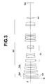
- an extender that changes the focal length of the entire system of the zoom lens toward the long focus side by being inserted into the optical path of the zoom lens may be arranged in a removable manner.
- the extender is arranged immediately on the image side of the second negative lens group G4b, as illustrated in Figure 3.
- Figure 3 is a cross section illustrating the structure of fourth lens group G4', in which extender Ex is inserted into the fourth lens group G4 illustrated in Figure 2 .
- the second negative lens group G4b which is an anti-vibration group, and the extender need to be driven by a drive device or devices. Therefore, if a fixed group is arranged between the anti-vibration group and the extender, the mechanism becomes complex, and that is not desirable.
- the most-object-side lens in the entire system of the zoom lens is made of glass.
- the zoom lens is used outdoors by being mounted on a surveillance camera or the like, the lens that is arranged on the most object side of the zoom lens is constantly exposed to sunlight. Therefore, if the most-object-side lens is a plastic glass, there is a risk that the quality of the most-object-side lens deteriorates or changes.
- this zoom lens is used in tough environment or conditions, it is desirable that a multi-layer coating for protection is applied. Further, an anti-reflection coating for reducing ghost light or the like may be applied alone or in addition to the coating for protection.
- optical member GC is arranged between the lens system and an image formation plane.
- a low-pass filter various filters that cut specific wavelength bands or the like may be arranged as the optical member GC.
- filters may be arranged between lenses.
- a coating that has a similar action to the filters may be applied to a surface of one of the lenses.
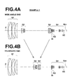
- Figures 4A and 4B are cross sections illustrating a zoom lens in Example 1.
- Figure 4A illustrates the arrangement of lenses at wide angle end
- Figure 4B illustrates the arrangement of lenses at telephoto end when the zoom lens is focused on an object at infinity.
- the left side is the object side
- the right side is the image side.
- aperture stop St, ND filter ND, and optical member GC are also illustrated in Figures 4A and 4B .
- Figures 5A and 5B are cross sections of a zoom lens in Example 2.
- Figures 6A and 6B are cross sections of a zoom lens in Example 3.
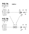
- Figures 7A and 7B are cross sections of a zoom lens in Example 4.
- Figures 8A and 8B are cross sections of a zoom lens in Example 5.
- Table 1 shows basic lens data about the zoom lens of Example 1
- Table 2 shows data about zoom of the zoom lens in Example 1.
- Tables 3 through 10 show basic lens data and data about zoom of the zoom lenses in Examples 2 through 5. The meanings of signs in the tables will be described by using the tables for Example 1. The meanings are basically similar to Example 1 in Examples 2 through 5.
- the surface number of the object-side surface of the most-object-side element is one, and the surface numbers sequentially increase toward the image side.
- the column Ri shows the radius of curvature of the i-th surface.
- the column Di shows a distance, on optical axis Z, between the i-th surface and the (i+1)th surface.
- the column of ⁇ dj shows the Abbe number of the j-th optical element with respect to d-line.
- the sign (plus or minus) of a radius of curvature is positive when the surface is convex toward the object side, and negative when the surface is convex toward the image side.
- the lens data includes aperture stop St, ND filter ND, and optical member GC.
- the term "(APERTURE STOP)" is written on a row corresponding to the aperture stop St.
- the numerical value at the bottom of the column of distances between surfaces is a distance between a surface of the optical member GC and an image plane.
- D8 is a distance between first lens group G1 and second lens group G2.
- D16 is a distance between the second lens group G2 and third lens group G3.
- D23 is a distance between the third lens group G3 and aperture stop St.
- Table 2 shows data about zoom.
- Table 2 shows focal length f of the entire system with respect to d-line, F-number (Fno.), full angle 2 ⁇ of view, and the values of D8, D16, and D23 at wide angle end, at middle focal length position, and at telephoto end.
- EXAMPLE 1 BASIC LENS DATA Si Ri Di Ndi ⁇ dj (SURFACE NUMBER) (CURVATURE OF RADIUS) (DISTANCE BETWEEN SURFACES) (REFRACTIVE INDEX) (Abbe NUMBER) 1 233.6026 2.900 1.51633 64.14 2 93.1487 20.486 1.618 63.33 3 -3833.7762 0.650 4 191.658 2.928 1.834807 42.71 5 78.1878 17.551 1.43875 94.93 6 635.5842 0.120 7 84.7498 14.210 1.43875 94.93 8 335.9694 D8 9 175.2338 1.304 1.882997 40.76 10 49.2827 8.414 11 131.2409 1.750 1.72342 37.95 12 17.9408 3.389 1.92286 18.9 13 34.6022 3.273 14 -56.1166 2.733 1.846609 23.78 15 -23
- EXAMPLE 2 BASIC LENS DATA Si Ri Di Ndj ⁇ dj (SURFACE NUMBER) (CURVATURE OF RADIUS) (DISTANCE BETWEEN SURFACES) (REFRACTIVE INDEX) (Abbe NUMBER) 1 294.3607 2.900 1.51633 64.14 2 97.8299 18.532 1.618 63.33 3 -1069.1708 0.120 4 192.7874 2.900 1.834807 42.71 5 77.4382 16.911 1.43875 94.93 6 662.8557 0.120 7 81.0121 13.454 1.43875 94.93 8 327.3442 D8 9 225.4275 1.200 1.882997 40.76 10 52.5241 2.143 11
- EXAMPLE 3 BASIC LENS DATA Si Ri Di Ndj ⁇ dj (SURFACE NUMBER) (CURVATURE OF RADIUS) (DISTANCE BETWEEN SURFACES) (REFRACTIVE INDEX) (Abbe NUMBER) 1 208.9115 3.309 1.522494 59.84 2 99.4181 18.674 1.592399 68.3 3 -1685.0654 1.987 4 166.830 6.211 1.834807 42.71 5 77.2468 18.340 1.43875 94.93 6 573.8424 0.584 7 77.8302 14.794 1.43875 94.93 8 256.4075 D8 9 327.3412 3.410 1.882997 40.76 10 46.73
- EXAMPLE 4 BASIC LENS DATA Si Ri Di Ndi ⁇ dj (SURFACE NUMBER) (CURVATURE OF RADIUS) (DISTANCE BETWEEN SURFACES) (REFRACTIVE INDEX) (Abbe NUMBER) 1 215.5379 3.171 1.48749 70.23 2 88.9466 20.054 1.618 63.33 3 -9653.7791 0.168 4 211.6353 3.926 1.834807 42.71 5 74.9054 17.360 1.43875 94.93 6 509.263 0.200 7 86.9727 15.646 1.496999 81.54 8 288.7008 D8 9 147.2507 1.419 1.882997 40.76 10 51.92
- EXAMPLE 5 BASIC LENS DATA Si Ri Di Ndi ⁇ di (SURFACE NUMBER) (CURVATURE OF RADIUS) (DISTANCE BETWEEN SURFACES) (REFRACTIVE INDEX) (Abbe NUMBER) 1 210.9815 3.218 1.522494 59.84 2 102.8806 18.559 1.569075 71.3 3 -995.4027 1.985 4 165.4025 7.408 1.834807 42.71 5 78.124 18.093 1.43875 94.93 6 592.3707 0.510 7 77.8117 14.387 1.43875 94.93 8 256.1136 D8 9 391.5615 2.461 1.882997 40.76 10 47.8569 12.
- Table 11 shows values corresponding to formulas (1) through (6) with respect to the zoom lenses in Examples 1 through 5. Table 11 shows values with respect to d-line.
- EXAMPLE1 EXAMPLE2
- EXAMPLE3 EXAMPLE4
- EXAMPLE5 (1) fG1/ft 0.178 0.176 0.168 0.223 0.171 (2) ⁇ n 53.4 53.4 51.3 56.5 51.3 (3) ⁇ p 84.4 84.4 86.1 79.9 87.1 (4) ⁇ ⁇ 1 0.8 0.8 8.5 6.9 11.5 (5) ⁇ ⁇ 2 52.2 52.2 52.2 52.2 52.2 (6) f4a/f4b 3.03 3.01 2.06 2.42 2.67 fG1 172.309 169.958 154.659 180.521 152.962 f4a -157.60 -154.58 -122.35 -130.86 -142.27 f4b -52.08 -51.43 -59.38 -54.07 -53.35
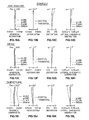
- Figures 9A through 9D are diagrams illustrating various aberrations (spherical aberration, astigmatism, distortion, and lateral chromatic aberration, respectively) of the zoom lens in Example 1 at wide angle end.
- Figures 9E through 9H are diagrams illustrating various aberrations (spherical aberration, astigmatism, distortion, and lateral chromatic aberration, respectively) of the zoom lens in Example 1 at middle focal length position.
- Figures 9I through 9L are diagrams illustrating various aberrations (spherical aberration, astigmatism, distortion, and lateral chromatic aberration, respectively) of the zoom lens in Example 1 at telephoto end.
- the diagrams illustrate aberrations with respect to d-line. Further, the diagrams of spherical aberrations illustrate aberrations with respect to g-line (wavelength is 435.8 nm), C-line (wavelength is 656.3 nm), and the wavelength of 880 nm. Further, the diagrams of lateral chromatic aberrations illustrate aberrations with respect to g-line, C-line, and the wavelength of 880 nm. Further, in the diagrams of astigmatism, aberrations with respect to a sigittal direction are represented by solid lines, and aberrations with respect to a tangential direction are represented by dotted lines. In the diagrams of spherical aberrations, the sign "Fno.” represents an F-number, and in the other diagrams, ⁇ represents a half angle of view.
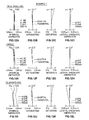
- Figures 10A through 10L are diagrams illustrating various aberrations of the zoom lens in Example 2 at wide angle end, at middle focal length position, and at telephoto end.
- Figures 11A through 11L are diagrams illustrating various aberrations of the zoom lens in Example 3 at wide angle end, at middle focal length position, and at telephoto end.
- Figures 12A through 12L are diagrams illustrating various aberrations of the zoom lens in Example 4 at wide angle end, at middle focal length position, and at telephoto end.
- Figures 13A through 13L are diagrams illustrating various aberrations of the zoom lens in Example 5 at wide angle end, at middle focal length position, and at telephoto end. All of the diagrams of aberrations illustrate aberrations when a distance to an object is 50 m.
- the zoom lenses in Examples 1 through 5 have high variable magnification ratios of approximately 57 times. While the zoom lenses are relatively compact as high variable magnification optical systems, the zoom lenses can achieve high optical performance in which aberrations are corrected in an excellent manner in a wide wavelength band of visible light to a near-infrared region through the whole variable magnification range.
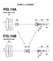
- Figures 14A and 14B are cross sections of the zoom lens in Example 1 when extender Ex having a magnification (multiplication) of 2 times is inserted.
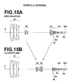
- Figures 15A and 15B are cross sections of the zoom lens in Example 2 when extender Ex having a magnification (multiplication) of 2 times is inserted.
- the extender Ex is inserted immediately on the image side of the second negative lens group G4b in the fourth lens group G4.
- the fourth lens group is represented by the sign "G4"' when the extender Ex is inserted into the fourth lens group G4.
- Table 12 shows basic lens data of the zoom lens in Example 1 when an extender is inserted.
- Table 13 shows data about zoom of the zoom lens in Example 1 when an extender is inserted.
- Table 14 shows basic lens data of the zoom lens in Example 2 when an extender is inserted.
- Table 15 shows data about zoom of the zoom lens in Example 2 when an extender is inserted. The meanings of the signs in Tables 12 through 15 are similar to those of Example 1, which were described already.
- Figure 16 is a schematic diagram illustrating the configuration of an example of an imaging apparatus according to an embodiment of the present invention.
- the imaging apparatus uses a zoom lens according to an embodiment of the present invention.
- the imaging apparatus is, for example, a surveillance camera, a video camera, an electronic still camera, or the like.
- An imaging apparatus 10 illustrated in Figure 16 includes a zoom lens 1, a filter 2, an imaging device 3, a signal processing unit 4, and a zoom control unit 5.
- the filter 2 is arranged on the image side of the zoom lens 1.
- the imaging device 3 performs imaging on an image of a subject formed by the zoom lens 1.
- the signal processing unit 4 performs operation processing on signals output from the imaging device 3.
- the zoom control unit 5 is provided to change the magnification of the zoom lens 1.
- the zoom lens 1 includes first lens group G1 having positive refractive power, second lens group G2 having negative refractive power, third lens group G3 having positive refractive power, aperture stop St and fourth lens group G4 having positive refractive power.
- first lens group G1 having positive refractive power
- second lens group G2 having negative refractive power
- third lens group G3 having positive refractive power
- aperture stop St and fourth lens group G4 having positive refractive power.
- these lens groups are conceptually illustrated.
- the imaging device 3 converts an optical image formed by the zoom lens 1 into electrical signals.
- the imaging device 3 is placed in such a manner that the imaging surface of the imaging device 3 and the image plane of the zoom lens 1 become the same.
- a CCD, a CMOS or the like may be used as the imaging device 3.
Landscapes
- Physics & Mathematics (AREA)
- General Physics & Mathematics (AREA)
- Optics & Photonics (AREA)
- Lenses (AREA)
- Adjustment Of Camera Lenses (AREA)
Applications Claiming Priority (1)
| Application Number | Priority Date | Filing Date | Title |
|---|---|---|---|
| JP2010169991A JP5438620B2 (ja) | 2010-07-29 | 2010-07-29 | ズームレンズおよび撮像装置 |
Publications (1)
| Publication Number | Publication Date |
|---|---|
| EP2413178A1 true EP2413178A1 (en) | 2012-02-01 |
Family
ID=44720241
Family Applications (1)
| Application Number | Title | Priority Date | Filing Date |
|---|---|---|---|
| EP11175628A Withdrawn EP2413178A1 (en) | 2010-07-29 | 2011-07-27 | Zoom lens and imaging apparatus |
Country Status (4)
| Country | Link |
|---|---|
| US (1) | US8254036B2 (enExample) |
| EP (1) | EP2413178A1 (enExample) |
| JP (1) | JP5438620B2 (enExample) |
| CN (1) | CN102346292B (enExample) |
Cited By (1)
| Publication number | Priority date | Publication date | Assignee | Title |
|---|---|---|---|---|
| CN115685512A (zh) * | 2022-11-23 | 2023-02-03 | 福建福光股份有限公司 | 具有恒等光圈超大变倍比的变焦光学系统及其成像方法 |
Families Citing this family (21)
| Publication number | Priority date | Publication date | Assignee | Title |
|---|---|---|---|---|
| JP5665489B2 (ja) * | 2010-11-10 | 2015-02-04 | キヤノン株式会社 | ズームレンズ及びそれを有する撮像装置 |
| JP2013130614A (ja) * | 2011-12-20 | 2013-07-04 | Sony Corp | ズームレンズおよび撮像装置 |
| CN102590991B (zh) * | 2012-04-01 | 2013-10-30 | 昆明物理研究所 | U型折叠式中波红外30倍连续变焦光学系统 |
| EP2916155B1 (en) * | 2012-10-31 | 2017-07-19 | Han's Laser Technology Industry Group Co., Ltd. | Variofocusing monitoring shot and monitoring device |
| CN104769475B (zh) * | 2012-11-08 | 2017-04-05 | 富士胶片株式会社 | 变焦透镜和摄像装置 |
| TWI463173B (zh) | 2013-07-25 | 2014-12-01 | Young Optics Inc | 變焦鏡頭 |
| US9459434B2 (en) * | 2013-08-28 | 2016-10-04 | Ricoh Company, Ltd. | Zoom lens and imaging apparatus |
| CN104199178B (zh) * | 2014-08-06 | 2017-03-29 | 青岛歌尔声学科技有限公司 | 一种变焦镜头 |
| JP6544975B2 (ja) * | 2015-04-10 | 2019-07-17 | キヤノン株式会社 | ズームレンズおよび撮像装置 |
| CN107076967B (zh) * | 2015-09-07 | 2020-09-01 | Hoya株式会社 | 内窥镜用变倍光学系统及内窥镜 |
| JP6643049B2 (ja) | 2015-11-10 | 2020-02-12 | キヤノン株式会社 | 光学系及びそれを有する撮像装置 |
| WO2017159325A1 (ja) | 2016-03-16 | 2017-09-21 | 富士フイルム株式会社 | エクステンダーレンズおよび撮像装置 |
| JP6670262B2 (ja) * | 2017-02-24 | 2020-03-18 | 富士フイルム株式会社 | ズームレンズおよび撮像装置 |
| JP6695293B2 (ja) * | 2017-03-07 | 2020-05-20 | 富士フイルム株式会社 | ズームレンズおよび撮像装置 |
| JP7033916B2 (ja) * | 2017-12-28 | 2022-03-11 | Omデジタルソリューションズ株式会社 | 撮像光学系及びそれを備えた撮像装置 |
| JP7211926B2 (ja) * | 2019-11-12 | 2023-01-24 | 富士フイルム株式会社 | ズームレンズおよび撮像装置 |
| CN111239969A (zh) * | 2020-02-24 | 2020-06-05 | 嘉兴中润光学科技有限公司 | 一种切换式投影用光学系统和图像拾取装置 |
| CN111308660B (zh) * | 2020-03-16 | 2025-05-09 | 江西欧菲光学有限公司 | 光学系统、摄像模组及电子装置 |
| CN113176654B (zh) * | 2021-04-28 | 2022-08-09 | 天津欧菲光电有限公司 | 光学系统、镜头模组和电子设备 |
| CN114355589B (zh) * | 2021-12-29 | 2023-07-28 | 福建福光股份有限公司 | 一种31倍小型化连续变焦距镜头 |
| CN116165782B (zh) * | 2022-12-25 | 2024-03-15 | 福建福光股份有限公司 | 一种带透雾30倍高清长焦连续变焦镜头 |
Citations (8)
| Publication number | Priority date | Publication date | Assignee | Title |
|---|---|---|---|---|
| JP2001356381A (ja) * | 2000-06-16 | 2001-12-26 | Canon Inc | 防振機能を有したズームレンズ及びそれを用いた光学機器 |
| US20040169934A1 (en) * | 2003-02-28 | 2004-09-02 | Makoto Oomura | Large zoom ratio, four-group zoom lens |
| US20050180024A1 (en) * | 2004-02-12 | 2005-08-18 | Fujinon Corporation | Large zoom ratio zoom lens |
| EP1582902A1 (en) * | 2004-03-31 | 2005-10-05 | Canon Kabushiki Kaisha | Zoom lens |
| JP2006039005A (ja) | 2004-07-23 | 2006-02-09 | Fujinon Corp | ズームレンズ |
| US20070058264A1 (en) * | 2005-09-12 | 2007-03-15 | Canon Kabushiki Kaisha | Zoom lens and image pickup apparatus having the same |
| EP1975666A1 (en) * | 2007-03-26 | 2008-10-01 | Fujinon Corporation | Zoom lens of the telephoto type with a fixed first lens group |
| US20090086321A1 (en) * | 2007-10-02 | 2009-04-02 | Nikon Corporation | Zoom lens system, optical apparatus, and method for manufacturing zoom lens system |
Family Cites Families (4)
| Publication number | Priority date | Publication date | Assignee | Title |
|---|---|---|---|---|
| JP2007003776A (ja) * | 2005-06-23 | 2007-01-11 | Sony Corp | ズームレンズ及び撮像装置 |
| JP4880498B2 (ja) * | 2007-03-01 | 2012-02-22 | 株式会社タムロン | 望遠ズームレンズ |
| JP5328284B2 (ja) * | 2008-10-08 | 2013-10-30 | キヤノン株式会社 | ズームレンズ及びそれを有する撮像装置 |
| JP2010102096A (ja) * | 2008-10-23 | 2010-05-06 | Fujinon Corp | ズームレンズおよび撮像装置 |
-
2010
- 2010-07-29 JP JP2010169991A patent/JP5438620B2/ja active Active
-
2011
- 2011-07-27 EP EP11175628A patent/EP2413178A1/en not_active Withdrawn
- 2011-07-28 US US13/193,103 patent/US8254036B2/en active Active
- 2011-07-29 CN CN201110216839.5A patent/CN102346292B/zh active Active
Patent Citations (9)
| Publication number | Priority date | Publication date | Assignee | Title |
|---|---|---|---|---|
| JP2001356381A (ja) * | 2000-06-16 | 2001-12-26 | Canon Inc | 防振機能を有したズームレンズ及びそれを用いた光学機器 |
| US20040169934A1 (en) * | 2003-02-28 | 2004-09-02 | Makoto Oomura | Large zoom ratio, four-group zoom lens |
| US20050180024A1 (en) * | 2004-02-12 | 2005-08-18 | Fujinon Corporation | Large zoom ratio zoom lens |
| EP1582902A1 (en) * | 2004-03-31 | 2005-10-05 | Canon Kabushiki Kaisha | Zoom lens |
| JP2006039005A (ja) | 2004-07-23 | 2006-02-09 | Fujinon Corp | ズームレンズ |
| US20070058264A1 (en) * | 2005-09-12 | 2007-03-15 | Canon Kabushiki Kaisha | Zoom lens and image pickup apparatus having the same |
| EP1975666A1 (en) * | 2007-03-26 | 2008-10-01 | Fujinon Corporation | Zoom lens of the telephoto type with a fixed first lens group |
| JP2008241884A (ja) | 2007-03-26 | 2008-10-09 | Fujinon Corp | 高倍率ズームレンズおよび撮像装置 |
| US20090086321A1 (en) * | 2007-10-02 | 2009-04-02 | Nikon Corporation | Zoom lens system, optical apparatus, and method for manufacturing zoom lens system |
Cited By (2)
| Publication number | Priority date | Publication date | Assignee | Title |
|---|---|---|---|---|
| CN115685512A (zh) * | 2022-11-23 | 2023-02-03 | 福建福光股份有限公司 | 具有恒等光圈超大变倍比的变焦光学系统及其成像方法 |
| CN115685512B (zh) * | 2022-11-23 | 2024-03-15 | 福建福光股份有限公司 | 具有恒等光圈超大变倍比的变焦光学系统及其成像方法 |
Also Published As
| Publication number | Publication date |
|---|---|
| US8254036B2 (en) | 2012-08-28 |
| JP5438620B2 (ja) | 2014-03-12 |
| CN102346292B (zh) | 2015-03-25 |
| US20120026604A1 (en) | 2012-02-02 |
| CN102346292A (zh) | 2012-02-08 |
| JP2012032469A (ja) | 2012-02-16 |
Similar Documents
| Publication | Publication Date | Title |
|---|---|---|
| US8254036B2 (en) | Zoom lens and imaging apparatus | |
| US7894135B2 (en) | Zoom lens and image pickup apparatus including the lens | |
| JP5624377B2 (ja) | ズームレンズおよび撮像装置 | |
| US7688520B2 (en) | Zoom lens system and camera including the same | |
| JP4030743B2 (ja) | ズームレンズ系 | |
| EP2388634A1 (en) | Variable magnification optical system and imaging apparatus | |
| US8947786B2 (en) | Variable magnification optical system and imaging apparatus | |
| US9612424B2 (en) | Imaging lens and imaging apparatus | |
| WO2014115230A1 (ja) | ズームレンズおよび撮像装置 | |
| JP4280538B2 (ja) | ズームレンズ | |
| WO2012077338A1 (ja) | ズームレンズおよび撮像装置 | |
| JP5680673B2 (ja) | ズームレンズおよび撮像装置 | |
| US20060285221A1 (en) | Zoom lens system and lens barrel having the same | |
| CN107544129A (zh) | 变焦透镜及摄像装置 | |
| CN104620153A (zh) | 变焦镜头以及摄像装置 | |
| JP4597623B2 (ja) | ズームレンズ | |
| CN104067157A (zh) | 变焦镜头、光学设备以及变焦镜头的制造方法 | |
| CN112859310A (zh) | 变焦镜头及摄像装置 | |
| JP2010066661A (ja) | ズームレンズおよび撮像装置 | |
| JP2016095448A (ja) | ズームレンズ及びそれを有する撮像装置 | |
| WO2013031110A1 (ja) | ズームレンズおよび撮像装置 | |
| US9030753B2 (en) | Zoom lens and imaging apparatus | |
| US7675691B2 (en) | Zoom lens system and imaging optical device employing the same | |
| JP2016062054A (ja) | ズームレンズおよびこれを用いた撮像装置 | |
| JP5583861B2 (ja) | ズームレンズおよび撮像装置 |
Legal Events
| Date | Code | Title | Description |
|---|---|---|---|
| AK | Designated contracting states |
Kind code of ref document: A1 Designated state(s): AL AT BE BG CH CY CZ DE DK EE ES FI FR GB GR HR HU IE IS IT LI LT LU LV MC MK MT NL NO PL PT RO RS SE SI SK SM TR |
|
| AX | Request for extension of the european patent |
Extension state: BA ME |
|
| PUAI | Public reference made under article 153(3) epc to a published international application that has entered the european phase |
Free format text: ORIGINAL CODE: 0009012 |
|
| RTI1 | Title (correction) |
Free format text: ZOOM LENS AND IMAGING APPARATUS |
|
| 17P | Request for examination filed |
Effective date: 20120726 |
|
| STAA | Information on the status of an ep patent application or granted ep patent |
Free format text: STATUS: THE APPLICATION IS DEEMED TO BE WITHDRAWN |
|
| 18D | Application deemed to be withdrawn |
Effective date: 20140201 |