EP2412564B1 - Driver's compartment and method of designing same - Google Patents
Driver's compartment and method of designing same Download PDFInfo
- Publication number
- EP2412564B1 EP2412564B1 EP11175447.9A EP11175447A EP2412564B1 EP 2412564 B1 EP2412564 B1 EP 2412564B1 EP 11175447 A EP11175447 A EP 11175447A EP 2412564 B1 EP2412564 B1 EP 2412564B1
- Authority
- EP
- European Patent Office
- Prior art keywords
- seat
- driver
- vertical distance
- srp
- compartment
- Prior art date
- Legal status (The legal status is an assumption and is not a legal conclusion. Google has not performed a legal analysis and makes no representation as to the accuracy of the status listed.)
- Not-in-force
Links
Images



Classifications
-
- F—MECHANICAL ENGINEERING; LIGHTING; HEATING; WEAPONS; BLASTING
- F41—WEAPONS
- F41H—ARMOUR; ARMOURED TURRETS; ARMOURED OR ARMED VEHICLES; MEANS OF ATTACK OR DEFENCE, e.g. CAMOUFLAGE, IN GENERAL
- F41H7/00—Armoured or armed vehicles
- F41H7/02—Land vehicles with enclosing armour, e.g. tanks
-
- B—PERFORMING OPERATIONS; TRANSPORTING
- B60—VEHICLES IN GENERAL
- B60N—SEATS SPECIALLY ADAPTED FOR VEHICLES; VEHICLE PASSENGER ACCOMMODATION NOT OTHERWISE PROVIDED FOR
- B60N2/00—Seats specially adapted for vehicles; Arrangement or mounting of seats in vehicles
- B60N2/02—Seats specially adapted for vehicles; Arrangement or mounting of seats in vehicles the seat or part thereof being movable, e.g. adjustable
- B60N2/04—Seats specially adapted for vehicles; Arrangement or mounting of seats in vehicles the seat or part thereof being movable, e.g. adjustable the whole seat being movable
-
- B—PERFORMING OPERATIONS; TRANSPORTING
- B60—VEHICLES IN GENERAL
- B60N—SEATS SPECIALLY ADAPTED FOR VEHICLES; VEHICLE PASSENGER ACCOMMODATION NOT OTHERWISE PROVIDED FOR
- B60N2/00—Seats specially adapted for vehicles; Arrangement or mounting of seats in vehicles
- B60N2/02—Seats specially adapted for vehicles; Arrangement or mounting of seats in vehicles the seat or part thereof being movable, e.g. adjustable
- B60N2/04—Seats specially adapted for vehicles; Arrangement or mounting of seats in vehicles the seat or part thereof being movable, e.g. adjustable the whole seat being movable
- B60N2/06—Seats specially adapted for vehicles; Arrangement or mounting of seats in vehicles the seat or part thereof being movable, e.g. adjustable the whole seat being movable slidable
-
- B—PERFORMING OPERATIONS; TRANSPORTING
- B60—VEHICLES IN GENERAL
- B60N—SEATS SPECIALLY ADAPTED FOR VEHICLES; VEHICLE PASSENGER ACCOMMODATION NOT OTHERWISE PROVIDED FOR
- B60N2/00—Seats specially adapted for vehicles; Arrangement or mounting of seats in vehicles
- B60N2/02—Seats specially adapted for vehicles; Arrangement or mounting of seats in vehicles the seat or part thereof being movable, e.g. adjustable
- B60N2/04—Seats specially adapted for vehicles; Arrangement or mounting of seats in vehicles the seat or part thereof being movable, e.g. adjustable the whole seat being movable
- B60N2/16—Seats specially adapted for vehicles; Arrangement or mounting of seats in vehicles the seat or part thereof being movable, e.g. adjustable the whole seat being movable height-adjustable
-
- B—PERFORMING OPERATIONS; TRANSPORTING
- B60—VEHICLES IN GENERAL
- B60N—SEATS SPECIALLY ADAPTED FOR VEHICLES; VEHICLE PASSENGER ACCOMMODATION NOT OTHERWISE PROVIDED FOR
- B60N2/00—Seats specially adapted for vehicles; Arrangement or mounting of seats in vehicles
- B60N2/02—Seats specially adapted for vehicles; Arrangement or mounting of seats in vehicles the seat or part thereof being movable, e.g. adjustable
- B60N2/04—Seats specially adapted for vehicles; Arrangement or mounting of seats in vehicles the seat or part thereof being movable, e.g. adjustable the whole seat being movable
- B60N2/16—Seats specially adapted for vehicles; Arrangement or mounting of seats in vehicles the seat or part thereof being movable, e.g. adjustable the whole seat being movable height-adjustable
- B60N2/18—Seats specially adapted for vehicles; Arrangement or mounting of seats in vehicles the seat or part thereof being movable, e.g. adjustable the whole seat being movable height-adjustable the front or the rear portion of the seat being adjustable, e.g. independently of each other
-
- B—PERFORMING OPERATIONS; TRANSPORTING
- B60—VEHICLES IN GENERAL
- B60N—SEATS SPECIALLY ADAPTED FOR VEHICLES; VEHICLE PASSENGER ACCOMMODATION NOT OTHERWISE PROVIDED FOR
- B60N2/00—Seats specially adapted for vehicles; Arrangement or mounting of seats in vehicles
- B60N2/02—Seats specially adapted for vehicles; Arrangement or mounting of seats in vehicles the seat or part thereof being movable, e.g. adjustable
- B60N2/04—Seats specially adapted for vehicles; Arrangement or mounting of seats in vehicles the seat or part thereof being movable, e.g. adjustable the whole seat being movable
- B60N2/16—Seats specially adapted for vehicles; Arrangement or mounting of seats in vehicles the seat or part thereof being movable, e.g. adjustable the whole seat being movable height-adjustable
- B60N2/18—Seats specially adapted for vehicles; Arrangement or mounting of seats in vehicles the seat or part thereof being movable, e.g. adjustable the whole seat being movable height-adjustable the front or the rear portion of the seat being adjustable, e.g. independently of each other
- B60N2/1807—Seats specially adapted for vehicles; Arrangement or mounting of seats in vehicles the seat or part thereof being movable, e.g. adjustable the whole seat being movable height-adjustable the front or the rear portion of the seat being adjustable, e.g. independently of each other characterised by the cinematic
- B60N2/1835—Seats specially adapted for vehicles; Arrangement or mounting of seats in vehicles the seat or part thereof being movable, e.g. adjustable the whole seat being movable height-adjustable the front or the rear portion of the seat being adjustable, e.g. independently of each other characterised by the cinematic pivoting about an axis located in the front
Definitions
- the subject matter of the present application relates to a method of designing a driver's compartment for accommodating a predetermined range of driver's sizes comprising a smallest size and a largest size, and a movable driver's seat for the driver's compartment, (see for example, US 2 088 784 A corresponding to the preamble of either independent method claim or independent product claim 13).
- the size of a driver's compartment can be significantly larger than would be the case for a driver's compartment which is designed for only a driver of a single size.
- EP 2 174 828 A discloses a seat having a guiding device for guiding a seat base between a top front end position and a bottom rear end position.
- the guiding device includes a support fixed to a chassis of a vehicle.
- the support includes a guiding surface that includes an upper flange, oriented longitudinally and turned upward.
- the guiding device has a displacement unit i.e. roller, mounted on the seat base, where the displacement unit cooperates with the guiding surface to allow movement of the seat between the end positions.
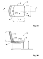
- the term "driver's seat” includes the following features, described with reference to a seat generally designated as 10 in Figs. 3A and 3B : a base portion 12 and a back portion 14 ; the base portion comprising an upper surface 16 , the upper surface 16 having opposing front and rear edges (18,20) and side edges (22,24) extending therebetween; a Seat Reference Point (SRP) on the upper surface 16 of the base portion 12 being disposed equally spaced from the side edges (22,24) thereof and at an area of intersection of the back portion 14 and the upper surface 16 .
- SRP Seat Reference Point
- an SRP in the present application refers to a position of a part of a seat in a driver's compartment, and corresponds in meaning to that shown in Fig. 44 of the military standard MIL-STD-1472F, upon which Figs. 3A and 3B are based.
- SPHRP Seat Pan Height Reference Point
- the method above can enable a driver's compartment to be smaller than would be the case in the comparative examples shown in Figs. 1 and 2 , where the driver of the largest size is seen to sit at a height greater than a driver of a smaller size.
- An advantage of the method can be that a design of the driver's compartment can suit a range of sizes of drivers, by designing a seating position of a larger driver to be lower position than a smaller driver, which is larger than a range of sizes enabled with conventional seating positions, i.e. with the larger driver being seated higher up.
- the method can further include limiting a vertical dimension of at least the front window area of the compartment to suit the vision cone of the largest size driver in the second position.
- the material thereof having the highest areal density is the transparent material constituted by the vehicle's glass and/or transparent armor (for military vehicles).
- An advantage of reducing the window area of a driver's compartment can be improved mobility of the vehicle. According to one design, such method can allow a 100mm change in height between the SRP of the largest and smallest driver to achieve a reduction of approximately 14% per meter squared of transparent material in a driver's compartment.
- the method can further include designing the driver's seat to be movable by said seat moving mechanism into a number of additional positions between the first and second positions, the vertical distance of the SRP from the top end in said additional positions gradually increasing in the direction towards the second position.
- the method can further include configuring a front edge of a base portion to move only along a horizontal plane.
- the method can further include configuring an SPHRP to move only along a horizontal plane.
- An advantage of reducing the vertical dimension of the roof of a driver's compartment can be the improved mobility of the vehicle.
- Pedals minimum 5 cm (2 in) H. Boot (provide adequate clearance to operate accelerator without interference by brake pedal) 15 cm (6 in) 1. Head (seat reference point (SRP) to roof line) 107 cm (42 in) 2. Abdominal (seat back to steering wheel) 41 cm (16 in) 3. front of knee (seat back to manual controls on dash) 74 cm (29 in) 4. Seat depth (seat reference point to front edge of seat pan) 41 cm (16 in) 5. Thigh (under side of steering wheel to seat pan) 24 cm (9.5 in) 6. Seat pan height 38 3 cm (15 in) 7. Boot (front of seat pan to heel point of accelerator) 36 cm (14 in) 8. Minimum mitten clearance around steering wheel 8 cm (3 in) 9. Knee-leg-thigh (brake/clutch pedals to lower edge of steering wheel) 66 cm (26 in)
- the method can include designing the driver's compartment to comply with any combination of the recommended clearances in the table above.
- the top end such as the compartment's ceiling can be limited in accordance with a specific ratio of the SRP.
- the method can include limiting a ratio of a vertical distance from the SRP to the floor and H2 in said second position, to not exceed 330:1070.
- the method can also include limiting a vertical dimension of the top end to suit the vertical distance of the SRP from the floor and a vertical distance from the SRP to the top end H1, in said first position of the smallest size driver, to not exceed 347:1053.
- the method can further include limiting a ratio of a vertical distance from the SRP to the floor and H2 in said second position, to not exceed 290:1070.
- the method can also include limiting a vertical dimension of the top end to suit the vertical distance of the SRP from the floor and a vertical distance from the SRP to the top end H1, in said first position of the smallest size driver, to not exceed 347:1053.
- the method can include limiting a ratio of a vertical distance from the SRP to the floor and H2 in said second position, to between 280:1070 and 290:1070.
- the method can include limiting a ratio of a vertical distance from the SRP to the floor and H2 in said second position, to not exceed 280:1020.
- the method can also include limiting a vertical dimension of the top end to suit the vertical distance of the SRP from the floor and a vertical distance from the SRP to the top end H1, in said first position of the smallest size driver, to not exceed 347:953.
- the method can further include limiting a ratio of the horizontal motion to vertical motion of the SRP to 2.8:1.
- the method can further include designing the driver's compartment to be protected by armor.
- a vehicle comprising a driver's compartment having a front window area, a driver's seat and a seat moving mechanism; the driver's seat having a seat reference point (SRP) used to define a position of a corresponding part of the seat in the compartment; the seat moving mechanism being configured to move the driver's seat into a number of positions, each different position including the SRP at a different horizontal distance from the front window area and a different vertical distance from the floor, each position having a horizontal distance the front window area which is greater than a different position having a vertical distance of the SRP from the floor smaller then said different position.
- SRP seat reference point
- Such seat moving mechanism can have the advantage of overcoming a natural tendency of a driver to elevate the driver's seat to a maximum height in order to gain better vision.
- the vehicle can further comprise a seat pan height reference point (SPHRP) used to define a position of a corresponding part of the seat in the compartment, the seat moving mechanism being configured to maintain a vertical distance of the SPHRP from the floor at a constant height.
- SPHRP seat pan height reference point
- the seat moving mechanism can be configured to move the SRP at a ratio of horizontal distance to vertical distance of 1:2.8.
- the vehicle, driver's compartment, and driver's seat of the present aspect can have any combination of features described above in connection with the first aspect.
- the vehicle can be an armored vehicle.
- the driver's compartment can be designed to be compliant with MIL-STD-1472F. Accordingly:
- a driver's compartment generally designated as 30.
- the driver's compartment 30 comprises a top end, such as a ceiling 31 and a compartment floor 36.
- the compartment 30 is designed to accommodate a larger driver 32 and a smaller driver 34 while being seated on a vehicle seat, generally designated 29.
- a vehicle seat generally designated 29.
- each driver is seated on a driver's seat 29 as defined above, however for the purposes of explanation, in the present view, the seat is shown in two different positions, a large driver position and a small driver position, with schematic lines 35 , and 37 representing a back portion of a seat in the large driver position, and in the small driver position, respectively.
- SRP, SPHRP and imaginary lines 39 and 41 joining same are shown for both positions.
- the SRP for both positions is at approximately the same vertical distance (H1) from the ceiling 31 of the driver's compartment 30 .
- the SPHRP of the large driver position and the SPHRP of the small driver position are at different horizontal distances L1 and L2 from a front window area 38 of the driver's compartment 30 .
- the different horizontal distances L1 and L2 are approximately 200mm apart.
- the height of the compartment H4 must be designed to accommodate the seat with the larger driver 32 seated thereon, which is the sum of the height of the SPR and vertical distance H1 from the ceiling.
- a larger compartment is required, which in a case of an armored vehicle requires additional surface area to be protected.
- each of the two drivers 32 and 34 has a vision cone ( 40,42 ) which only partially overlaps the other's vision cone. Areas of the vision cones which do not overlap are designated as 44 and 46 .
- the front window area of the driver's compartment is designed to have a vertical height HW1 suited to accommodate both vision cones.
- HW1 vertical height
- a driver's compartment 50 having a top end, such as a ceiling 51 , and a compartment floor 56 .
- the compartment 50 is designed to accommodate a larger driver 32 and a smaller driver 34 , while being seated on seat 55 . It can be seen that in the first position the driver's compartment 50 , can accommodate a small driver 34 while being seated on seat 55 , with the SPR 1 being at a vertical distance H1 from the ceiling 51 . In the second position, the driver's compartment 50 , can accommodate a large driver 34 by moving seat 55 to the second position in which SRP 2 of the seat 55 is lowered thereby increasing the vertical distance H2 between the SRP 2 and the ceiling 51 . It is appreciated that the seat 55 can alternate between the first and the second position while maintaining the same horizontal distances (L1, L2), from a front window area 39 .
- the height of the compartment H4 can be smaller than the height of the compartment 30 of Fig. 4 .
- the vision cone 40 of the larger driver 32 in this design encompasses a vision cone (not seen) of the smaller driver 34.
- the front window area of the driver's compartment is designed to have a vertical height HW2, which is suited to accommodate both vision cones.
- the magnitude of HW2 is smaller than the magnitude of HW1 of Fig. 4 . This design allows for a smaller surface area to be protected, and for providing a smaller protected window surface.
- the SPHRP of both positions can be maintained at a common vertical height from the floor 56 , and the seat can be adjusted merely by reducing the height of the SRP of the larger driver, while maintaining the same horizontal distances (L1, L2), from a front window area 39.
- a gradient of the imaginary line 59 between the SPHRP 2 and the SRP 2 of the seat position accommodating the larger driver 32 will have a larger magnitude than the imaginary line 61 between the SPHRP 1 and the SRP 1 of the seat position accommodating the smaller driver 34 . It is appreciated that maintaining the SPHRP in a fix vertical position for example at height H3from the floor 56 , allows for further minimizing the size of the compartment 50.
- SPHRP according to some standard must be at a minimal height from the floor, for example, 380 mm, either for a small driver or for a large driver.
- a seat moving mechanism which is configured to move SRP in the compartment between the two vertical distances from the ceiling, while maintaining the SPHRP in a vertical distance of at least H3 from the floor, allows for a small driver and a large driver to be accommodated in the compartment 50 , while meeting the requirement of the vehicle seat standard.
- the seat moving mechanism can be configured to allow vertically moving SPHRP so long as a minimum vertical height of H3 is maintained.
- the seat in the compartment can be provided with a seat moving mechanism for vertically moving the SRP and SPHRP, as described hereinabove, while also allowing horizontally moving the seat.
- a seat moving mechanism for vertically moving the SRP and SPHRP, as described hereinabove, while also allowing horizontally moving the seat.
- a first position generally designated as 60A closest to a front window area of a driver's compartment (not shown) showing an SPHRP, designated as 61A , an SRP, designated as 62A , and an imaginary line joining same, designated as 63A .
- a second position is shown generally designated as 60B , with the elements thereof having numerals corresponding to the numerals of the first position with the addition of the designation character "B".
- the final position is designated by the character G, which is the position of greatest horizontal distance from the front window area 39.
- the SPHRP 61A of the first position 60A starts at position (0,380), each position is moved 33mm in a horizontal direction away from the front window area, the internal height of the compartment is 1350mm, and the length of the seat depth is 410mm (item no. 4 in Table 1 above).
- the X coordinates here are calculated as the vertical distance of SPR and the SPHRP with respect to the floor of the compartment.
- An example set of coordinates of the SPHRP and SRP for each position shown can be as follows: position Position designation suffix SPHRP SRP x y x y 1 A 0 380 408.44 344.27 2 B 33 380 407.36 333.59 3 C 66 380 406.01 322.94 4 D 99 380 404.38 312.33 5 E 132 380 402.47 301.77 6 F 165 380 400.28 291.26 7 G 198 380 397.82 280.81
- FIG. 7 A more accurate rendering of the horizontal spacing can be seen in Fig. 7 where the first, second and third positions ( 60A , 60B , 60C ) are shown to demonstrate horizontal motion of the SRP and SPHRP.
- a driver's compartment generally designated as 70 , of an armored vehicle (not shown).
- the driver's compartment 70 comprises a floor 71 , a roof, 73 , a front window area 72 comprising a window 79 made of transparent armor, a driver's seat 74 and a seat moving mechanism generally designated as 76 .
- the driver's seat comprising a back portion 78 , base portion 80 , and having a seat reference point (SRP) used to define a position of a corresponding part of the seat in the compartment, and a seat pan height reference point (SPHRP).
- SRP seat reference point
- SPHRP seat pan height reference point
- the seat moving mechanism 76 comprising rails 78 , front legs 80 configured to slide along the rails 78 and pivotally attached to a front point 82 of the base portion 80 , compressible springs 84 configured to slide along the rails 78 , and a lever mechanism 86 pivotally attached at point 88 to the floor 71 .
- the lever mechanism 86 further comprising a locking mechanism (not shown) for locking the lever mechanism 86 in a desired position, or releasing it from that position.
- a user can slide the seat 74 in a horizontal direction, designated by arrow 90 , away from the front window area 72, along the rails 78 .
- the lever mechanism 86 pivots at the floor 71 , causing the seat 74 to pivot in the direction of arrow 92 , about front point 82 , compressing springs 84 toward the floor 71 , and moving the SRP away from the ceiling 73 .
- the user can then lock the seat 74 at the desired orientation, with the SRP of the seat consequently being at a vertical distance from the ceiling 73 larger than is the case when the seat is closer to the front window area 72 . In this position, compartment 70 can accommodate a larger driver.
- the seat 74 can be moved in a direction opposite to arrow 90 , in which case the seat will translate horizontally towards the front window area and pivot about front point 82 in a direction opposite to arrow 92 , thereby moving the SPR toward the ceiling and allowing a small driver to be seated on seat 74 , while maintaining the required vision cone.
- the SPHRP is not displaced toward the floor 71, below a predetermined vertical distance, for example 380mm.
- Such seat can be used in a driver's compartment to achieve the positions described above.
Landscapes
- Engineering & Computer Science (AREA)
- Aviation & Aerospace Engineering (AREA)
- Transportation (AREA)
- Mechanical Engineering (AREA)
- General Engineering & Computer Science (AREA)
- Seats For Vehicles (AREA)
- Body Structure For Vehicles (AREA)
Description
- The subject matter of the present application relates to a method of designing a driver's compartment for accommodating a predetermined range of driver's sizes comprising a smallest size and a largest size, and a movable driver's seat for the driver's compartment, (see for example,
US 2 088 784 A corresponding to the preamble of either independent method claim or independent product claim 13). - Economic and regulatory considerations cause designers to design driver's compartments of vehicles to accommodate drivers of a range of different sizes. This includes sizing a multitude of features of a vehicle's driver's compartment to suit both an upper end and lower end of the range.
- An appreciation of the complexity of the features involved in merely positioning a driver in a driver's compartment can be received by review of known conventional driver's compartment designs shown in
Figs. 1 and 2 . This design takes into consideration vertical and or horizontal distances of different body parts of the driver form various elements in the driver's compartment, for example, the distance between the head and the front window, the distance between the knees and the floor, etc. - Consequent to the need to suit a driver's compartment to drivers of different sizes, the size of a driver's compartment can be significantly larger than would be the case for a driver's compartment which is designed for only a driver of a single size.
- Seat adjusting mechanisms are known for example from the above-mentional
US 2088784 which discloses an automobile seat adjuster adapted for use in connection with the front seat of an automobile, which device may be readily adjusted by the driver of the vehicle both as to height and for longitudinal position in the car. -
EP 2 174 828 A discloses a seat having a guiding device for guiding a seat base between a top front end position and a bottom rear end position. The guiding device includes a support fixed to a chassis of a vehicle. The support includes a guiding surface that includes an upper flange, oriented longitudinally and turned upward. The guiding device has a displacement unit i.e. roller, mounted on the seat base, where the displacement unit cooperates with the guiding surface to allow movement of the seat between the end positions. - Throughout the present application, reference will be made to a driver's seat.
- For the purposes of the specification and the claims, the term "driver's seat" includes the following features, described with reference to a seat generally designated as 10 in
Figs. 3A and 3B : abase portion 12 and aback portion 14; the base portion comprising anupper surface 16, theupper surface 16 having opposing front and rear edges (18,20) and side edges (22,24) extending therebetween; a Seat Reference Point (SRP) on theupper surface 16 of thebase portion 12 being disposed equally spaced from the side edges (22,24) thereof and at an area of intersection of theback portion 14 and theupper surface 16. - As will be understood, an SRP in the present application refers to a position of a part of a seat in a driver's compartment, and corresponds in meaning to that shown in Fig. 44 of the military standard MIL-STD-1472F, upon which
Figs. 3A and 3B are based. - Additionally, reference in the present application will be made to a Seat Pan Height Reference Point (SPHRP), which is a term that does not appear in MIL-STD-1472F, but is defined, with reference to
Figs. 3A and 3B , as a point disposed on thefront edge 18 of theupper surface 16 of thebase portion 12, the SPHRP being equally spaced from the side edges (22,24). - In accordance with a first aspect of the invention as defined in
claim 1, there is provided a method of designing a driver's compartment for accommodating a predetermined range of driver's sizes comprising a smallest size and a largest size, the compartment having a floor and a top end, the method including: - a. designing a driver's seat having a seat reference point (SRP) used to define a position of a corresponding part of the seat in the compartment and a seat pan height reference point (SPHRP) used to define a position of the front portion of the seat in the compartment;
- b. providing a seat moving mechanism configured to move at least said SRP vertically in the compartment between a first position in which the SRP is disposed at a first vertical distance H1 from the top end and the SPHRP is disposed at a vertical distance of at least H3 from the floor, and in which the seat is configured to accommodate a driver of the smallest size, and a second position in which the SRP is disposed at a second vertical distance H2 from the top end, and the SPHRP is disposed at a vertical distance of at least H3 from the floor, H2 being greater than H1 and in which the seat is configured to accommodate a driver of the largest size;
- c. disposing the top end at a vertical distance H4 from the floor, whereby the distance H4 corresponds to the sum of H1 and H3, so that the vertical distance H4 of the top end suits for accommodating the driver of the largest size only when the seat is in said second position.
- The method above can enable a driver's compartment to be smaller than would be the case in the comparative examples shown in
Figs. 1 and 2 , where the driver of the largest size is seen to sit at a height greater than a driver of a smaller size. An advantage of the method can be that a design of the driver's compartment can suit a range of sizes of drivers, by designing a seating position of a larger driver to be lower position than a smaller driver, which is larger than a range of sizes enabled with conventional seating positions, i.e. with the larger driver being seated higher up. - The method can further include limiting a vertical dimension of at least the front window area of the compartment to suit the vision cone of the largest size driver in the second position. It will be appreciated that in some vehicles the material thereof having the highest areal density is the transparent material constituted by the vehicle's glass and/or transparent armor (for military vehicles). An advantage of reducing the window area of a driver's compartment can be improved mobility of the vehicle. According to one design, such method can allow a 100mm change in height between the SRP of the largest and smallest driver to achieve a reduction of approximately 14% per meter squared of transparent material in a driver's compartment.
- The method can further include designing the driver's seat to be movable by said seat moving mechanism into a number of additional positions between the first and second positions, the vertical distance of the SRP from the top end in said additional positions gradually increasing in the direction towards the second position.
- a. designing the seat moving mechanism to maintain a vertical distance of the SPHRP from the floor at a constant height or a height gradually decreasing in the direction towards the second position; and
- b. designing the seat moving mechanism into a number of additional positions between the first and second positions, the vertical distance of the SRP from the top end in said additional positions gradually increasing in the direction towards the second position; a rate of increase of the vertical distance of the SRP from the top end in said additional positions in the direction towards the second position being greater than a rate of decrease of the vertical distance of the SPHRP from the floor in said additional positions in the direction towards the second position.
- The method can further include configuring a front edge of a base portion to move only along a horizontal plane. The method can further include configuring an SPHRP to move only along a horizontal plane.
- An advantage of reducing the vertical dimension of the roof of a driver's compartment can be the improved mobility of the vehicle.
- Another advantage can be that such reduction can allow a more compact driver's compartment design than would otherwise be achievable in a military vehicle produced in accordance with the recommended clearances of Table XX of MIL-STD-1472F, shown below.
TABLE XX. Recommended clearances around equipment operator's station to accommodate the 95th percentile soldier dressed in Arctic clothing. Operator seat in rear most position (Figure 45) A. Elbow (dynamic) 91 cm (36 in) B Elbow (static) 71 cm (28 m) C. Shoulder 58 cm (23 in) D. Knee width (minimum) 46 cm (18 in) E. Knee width (optimum) 61 cm (24 in) F. Boot (provide adequate clearance to operate brake pedal without madvertent acceleration operation) 15 cm (6 in) G. Pedals (minimum) 5 cm (2 in) H. Boot (provide adequate clearance to operate accelerator without interference by brake pedal) 15 cm (6 in) 1. Head (seat reference point (SRP) to roof line) 107 cm (42 in) 2. Abdominal (seat back to steering wheel) 41 cm (16 in) 3. front of knee (seat back to manual controls on dash) 74 cm (29 in) 4. Seat depth (seat reference point to front edge of seat pan) 41 cm (16 in) 5. Thigh (under side of steering wheel to seat pan) 24 cm (9.5 in) 6. Seat pan height 383 cm (15 in) 7. Boot (front of seat pan to heel point of accelerator) 36 cm (14 in) 8. Minimum mitten clearance around steering wheel 8 cm (3 in) 9. Knee-leg-thigh (brake/clutch pedals to lower edge of steering wheel) 66 cm (26 in) - The method can include designing the driver's compartment to comply with any combination of the recommended clearances in the table above.
- The top end, such as the compartment's ceiling can be limited in accordance with a specific ratio of the SRP. According to one example the method can include limiting a ratio of a vertical distance from the SRP to the floor and H2 in said second position, to not exceed 330:1070. In such case the method can also include limiting a vertical dimension of the top end to suit the vertical distance of the SRP from the floor and a vertical distance from the SRP to the top end H1, in said first position of the smallest size driver, to not exceed 347:1053. According to another example, the method can further include limiting a ratio of a vertical distance from the SRP to the floor and H2 in said second position, to not exceed 290:1070. In such case the method can also include limiting a vertical dimension of the top end to suit the vertical distance of the SRP from the floor and a vertical distance from the SRP to the top end H1, in said first position of the smallest size driver, to not exceed 347:1053. According to yet a further example, the method can include limiting a ratio of a vertical distance from the SRP to the floor and H2 in said second position, to between 280:1070 and 290:1070. According to another example, the method can include limiting a ratio of a vertical distance from the SRP to the floor and H2 in said second position, to not exceed 280:1020. In such case the method can also include limiting a vertical dimension of the top end to suit the vertical distance of the SRP from the floor and a vertical distance from the SRP to the top end H1, in said first position of the smallest size driver, to not exceed 347:953.
- The method can further include limiting a ratio of the horizontal motion to vertical motion of the SRP to 2.8:1.
- The method can further include designing the driver's compartment to be protected by armor.
- In accordance with another aspect of the invention, which is defined technical features set forth in claim 13, there is provided a vehicle comprising a driver's compartment having a front window area, a driver's seat and a seat moving mechanism; the driver's seat having a seat reference point (SRP) used to define a position of a corresponding part of the seat in the compartment; the seat moving mechanism being configured to move the driver's seat into a number of positions, each different position including the SRP at a different horizontal distance from the front window area and a different vertical distance from the floor, each position having a horizontal distance the front window area which is greater than a different position having a vertical distance of the SRP from the floor smaller then said different position.
- Such seat moving mechanism can have the advantage of overcoming a natural tendency of a driver to elevate the driver's seat to a maximum height in order to gain better vision.
- The vehicle can further comprise a seat pan height reference point (SPHRP) used to define a position of a corresponding part of the seat in the compartment, the seat moving mechanism being configured to maintain a vertical distance of the SPHRP from the floor at a constant height.
- The seat moving mechanism can be configured to move the SRP at a ratio of horizontal distance to vertical distance of 1:2.8.
- The vehicle, driver's compartment, and driver's seat of the present aspect can have any combination of features described above in connection with the first aspect.
- The vehicle can be an armored vehicle.
- In accordance with either of the aspects above, the driver's compartment can be designed to be compliant with MIL-STD-1472F. Accordingly:
- a vertical distance from the SRP to the roof in said second position, i.e. a position designed for a largest driver size in the range, can be 1400mm or less (item no. 1 of Table XX, the recommended clearance for the head);
- the largest size in the predetermined range of driver's sizes can be a 95th percentile soldier, compliant with section 5.12.1 and Table XX of MIL-STD-1472F.
- the smallest size in the predetermined range of driver's sizes can be a 5th percentile soldier compliant with section 5.12.1 of MIL-STD-1472F.
- It will be understood that the specific examples given with respect to MIL-STD-1472F are for understanding of the subject matter of the present invention. Therefore, should this standard be replaced in future with a subsequent updated standard having modified recommended clearances, the SRP, vertical distance from the SRP to the ceiling in said second position, largest size and smallest sizes in the predetermined range of driver's sizes can be designed in accordance with the updated standard.
- In order to understand the subject matter of the present application and to see how it can be carried out in practice, embodiments will now be described, by way of non-limiting example only, with reference to the accompanying drawings, in which:
-
Fig. 1 is a schematic side view of a design of a known truck driver's compartment; -
Fig. 2 is a schematic side view of a design of a known car driver's compartment; -
Fig. 3A is a schematic top view of a seat from Fig. 44 of MIL-STD 1472F with additional reference numerals added thereto; -
Fig. 3B is a schematic sectional side view of the seat inFig. 3A , also from Fig. 44 of MIL-STD 1472F with additional reference numerals added thereto; -
Fig. 4 is a schematic side view of a known driver's compartment designed to accommodate drivers of two different sizes; -
Fig. 5A is a schematic side view of a driver's compartment designed in accordance with the present invention, -
Fig. 5B is a schematic side view of the driver's compartment inFig. 5A , with a modified driver's position; -
Fig. 6 is a schematic representation of a side view of an SRP, SPHRP, and imaginary line connecting same, of a driver's seat in accordance with the subject matter of the present application, in different positions, the positions being spaced from each other for ease of explanation; -
Fig. 7 is a schematic representation of some of the positions of the SRP, SPHRP, and imaginary line inFig. 6 ; and -
Fig. 8 is a schematic side view of an example driver's seat. - Referring now to the drawings wherein like reference characters designate like or corresponding parts throughout several views, there is shown in
Fig. 4 a driver's compartment generally designated as 30. - The driver's
compartment 30 comprises a top end, such as aceiling 31 and acompartment floor 36. Thecompartment 30 is designed to accommodate alarger driver 32 and asmaller driver 34 while being seated on a vehicle seat, generally designated 29. It will be understood that in reality each driver is seated on a driver'sseat 29 as defined above, however for the purposes of explanation, in the present view, the seat is shown in two different positions, a large driver position and a small driver position, withschematic lines imaginary lines ceiling 31 of the driver'scompartment 30. In order to accommodate the two drivers, the SPHRP of the large driver position and the SPHRP of the small driver position are at different horizontal distances L1 and L2 from afront window area 38 of the driver'scompartment 30. The different horizontal distances L1 and L2, are approximately 200mm apart. - As a result of the different sizes of the small and large driver, the height of the compartment H4, must be designed to accommodate the seat with the
larger driver 32 seated thereon, which is the sum of the height of the SPR and vertical distance H1 from the ceiling. Thus, in order to accommodate large drivers a larger compartment is required, which in a case of an armored vehicle requires additional surface area to be protected. - In addition, as a result of their different sizes, each of the two
drivers - Referring now to
Fig. 5A , there is shown a driver'scompartment 50 having a top end, such as aceiling 51, and acompartment floor 56. Thecompartment 50 is designed to accommodate alarger driver 32 and asmaller driver 34, while being seated onseat 55. It can be seen that in the first position the driver'scompartment 50, can accommodate asmall driver 34 while being seated onseat 55, with the SPR1 being at a vertical distance H1 from theceiling 51. In the second position, the driver'scompartment 50, can accommodate alarge driver 34 by movingseat 55 to the second position in which SRP2 of theseat 55 is lowered thereby increasing the vertical distance H2 between the SRP2 and theceiling 51. It is appreciated that theseat 55 can alternate between the first and the second position while maintaining the same horizontal distances (L1, L2), from afront window area 39. - As a result of this design, the height of the compartment H4, can be smaller than the height of the
compartment 30 ofFig. 4 . This is due to the fact that SPR2 in the large driver position is lower than the SPR1 in the small driver position, thus compensating for the difference between the vertical distance H2 required in the large driver position and the vertical distance H1 required in the small driver position. This allows minimizing the overall size of the compartment, thereby reducing the amount of surface area to be protected. - In addition, as can be seen in
Fig. 5A , the vision cone 40 of thelarger driver 32 in this design encompasses a vision cone (not seen) of thesmaller driver 34. Thus, the front window area of the driver's compartment is designed to have a vertical height HW2, which is suited to accommodate both vision cones. The magnitude of HW2 is smaller than the magnitude of HW1 ofFig. 4 . This design allows for a smaller surface area to be protected, and for providing a smaller protected window surface. Turning now toFig. 5B , it can be seen that the SPHRP of both positions can be maintained at a common vertical height from thefloor 56, and the seat can be adjusted merely by reducing the height of the SRP of the larger driver, while maintaining the same horizontal distances (L1, L2), from afront window area 39. Thus, a gradient of theimaginary line 59 between the SPHRP2 and the SRP2 of the seat position accommodating thelarger driver 32 will have a larger magnitude than theimaginary line 61 between the SPHRP1 and the SRP1 of the seat position accommodating thesmaller driver 34. It is appreciated that maintaining the SPHRP in a fix vertical position for example at height H3from thefloor 56, allows for further minimizing the size of thecompartment 50. This is due to the fact that SPHRP according to some standard must be at a minimal height from the floor, for example, 380 mm, either for a small driver or for a large driver. Thus, providing a seat moving mechanism which is configured to move SRP in the compartment between the two vertical distances from the ceiling, while maintaining the SPHRP in a vertical distance of at least H3 from the floor, allows for a small driver and a large driver to be accommodated in thecompartment 50, while meeting the requirement of the vehicle seat standard. However, according to another example, the seat moving mechanism can be configured to allow vertically moving SPHRP so long as a minimum vertical height of H3 is maintained. - According to a further example, the seat in the compartment can be provided with a seat moving mechanism for vertically moving the SRP and SPHRP, as described hereinabove, while also allowing horizontally moving the seat. For ease of understanding of the vertical and horizontal movement of the SRP and SPHRP along a desired path, attention is directed to
Fig. 6 . - In
Fig. 6 a first position, generally designated as 60A closest to a front window area of a driver's compartment (not shown) showing an SPHRP, designated as 61A, an SRP, designated as 62A, and an imaginary line joining same, designated as 63A. - A second position is shown generally designated as 60B, with the elements thereof having numerals corresponding to the numerals of the first position with the addition of the designation character "B".
- Similarly third, fourth, fifth, sixth and seventh positions are shown. The final position is designated by the character G, which is the position of greatest horizontal distance from the
front window area 39. - Using X and Y coordinates, positions in millimeters, and assuming the following conditions: the
SPHRP 61A of thefirst position 60A starts at position (0,380), each position is moved 33mm in a horizontal direction away from the front window area, the internal height of the compartment is 1350mm, and the length of the seat depth is 410mm (item no. 4 in Table 1 above). Although the vertical positions of SPR and the SPHRP hereinabove were referred to with respect to the vertical distance from the ceiling, for the sake of clarity, the X coordinates here, are calculated as the vertical distance of SPR and the SPHRP with respect to the floor of the compartment. An example set of coordinates of the SPHRP and SRP for each position shown can be as follows:position Position designation suffix SPHRP SRP x y x y 1 A 0 380 408.44 344.27 2 B 33 380 407.36 333.59 3 C 66 380 406.01 322.94 4 D 99 380 404.38 312.33 5 E 132 380 402.47 301.77 6 F 165 380 400.28 291.26 7 G 198 380 397.82 280.81 - It will be understood that the horizontal spacing between the positions in
Fig. 6 is exaggerated in the drawing to allow understanding of the pivoting motion. - A more accurate rendering of the horizontal spacing can be seen in
Fig. 7 where the first, second and third positions (60A, 60B, 60C) are shown to demonstrate horizontal motion of the SRP and SPHRP. - Shown in
Fig. 8 is a driver's compartment, generally designated as 70, of an armored vehicle (not shown). The driver'scompartment 70 comprises afloor 71, a roof, 73, afront window area 72 comprising awindow 79 made of transparent armor, a driver'sseat 74 and a seat moving mechanism generally designated as 76. The driver's seat comprising aback portion 78,base portion 80, and having a seat reference point (SRP) used to define a position of a corresponding part of the seat in the compartment, and a seat pan height reference point (SPHRP). - The
seat moving mechanism 76 comprisingrails 78,front legs 80 configured to slide along therails 78 and pivotally attached to afront point 82 of thebase portion 80,compressible springs 84 configured to slide along therails 78, and alever mechanism 86 pivotally attached atpoint 88 to thefloor 71. Thelever mechanism 86 further comprising a locking mechanism (not shown) for locking thelever mechanism 86 in a desired position, or releasing it from that position. - In operation, when the
locking mechanism 86 is not in a locked state, a user can slide theseat 74 in a horizontal direction, designated byarrow 90, away from thefront window area 72, along therails 78. During this motion, thelever mechanism 86 pivots at thefloor 71, causing theseat 74 to pivot in the direction ofarrow 92, aboutfront point 82, compressing springs 84 toward thefloor 71, and moving the SRP away from theceiling 73. The user can then lock theseat 74 at the desired orientation, with the SRP of the seat consequently being at a vertical distance from theceiling 73 larger than is the case when the seat is closer to thefront window area 72. In this position,compartment 70 can accommodate a larger driver. As will be understood, theseat 74 can be moved in a direction opposite toarrow 90, in which case the seat will translate horizontally towards the front window area and pivot aboutfront point 82 in a direction opposite toarrow 92, thereby moving the SPR toward the ceiling and allowing a small driver to be seated onseat 74, while maintaining the required vision cone. In any event, in both positions the SPHRP is not displaced toward thefloor 71, below a predetermined vertical distance, for example 380mm. - Such seat can be used in a driver's compartment to achieve the positions described above.
Claims (13)
- A method of designing a driver's compartment (30) for accommodating a predetermined range of driver's sizes comprising a smallest size (34) and a largest size (32), the compartment having a floor (36), front window area (39) to be protected and a top end (31), the method including:a. designing a driver's seat (29) having a seat reference point (SRP) used to define a position of a corresponding part of the seat in the compartment and a seat pan height reference point (SPHRP) used to define a position of the front portion of the seat in the compartment (30);b. providing a seat moving mechanism (76) configured to move at least said SRP vertically in the compartment between a first position (60A) in which the SRP is disposed at a first vertical distance H1 from the top end (31) and the SPHRP is disposed at a vertical distance of at least H3 from the floor (36), and in which the seat (29) is configured to accommodate a driver of the smallest size (34), and a second position (60B) in which the SRP is disposed at a second vertical distance H2 from the top end (31), and the SPHRP is disposed at a vertical distance of at least H3 from the floor (36), H2 being greater than H1 and in which the seat (29) is configured to accommodate a driver of the largest size (32); characterised by:c. disposing the top end (31) at a vertical distance H4 from the floor (36), the distance H4 corresponds to the sum of H1 and H3, so that the vertical distance H4 of the top end (31) suits for accommodating the driver of the largest size (32) only when the seat (29) is in said second position (60B), thereby reducing said area to be protected.
- The method of claim 1, further including limiting a vertical dimension of at least front window area (38) of the compartment to suit the vision cone of the driver of the largest size (32) in the second position (60B).
- The method of claim 1 or 2, further including designing the driver's seat to be movable by said seat moving mechanism (76) into a number of additional positions between the first and second positions (60A, 60B), the vertical distance of the SRP from the top end (31) in said additional positions gradually increasing in the direction towards the second position (60B).
- The method of any one of claims 1 to 3, further including:d. designing the seat moving mechanism (76) to maintain a vertical distance of the SPHRP from the floor (36) at a constant height or a height gradually decreasing in the direction towards the second position;e. designing the seat moving mechanism into a number of additional positions between the first and second positions, the vertical distance of the SRP from the top end (31) in said additional positions gradually increasing in the direction towards the second position (60B) ; a rate of increase of the vertical distance of the SRP from the top end (31) in said additional positions in the direction towards the second position being greater than a rate of decrease of the vertical distance of the SPHRP from the floor (36) in said additional positions in the direction towards the second position.
- The method of any one of claims 1 to 4, further includes configuring the driver's seat (29) for horizontal motion including forward motion in a direction towards a front window area (38) of the compartment of the vehicle and rearward motion in a direction opposite thereto.
- The method of any one of claims 1 to 5, further including configuring an SPHRP to move only along a horizontal plane.
- The method of claim 1, further including limiting a ratio of a vertical distance from the SRP to the floor (36) and H2 in said second position (60B), to not exceed 330:1070.
- The method of claim 1, further including limiting a vertical dimension of the top end (31) to suit the vertical distance of the SRP from the floor (36) and a vertical distance H1 of the SRP from the top end (31), in said first position (60A) of the smallest size driver (34), to not exceed 347:1053.
- The method of claim 1, further including limiting a ratio of a vertical distance from the SRP to the floor (36) and H2 in said second position (60B), to not exceed 290:1070.
- The method of claim 1, further including limiting a ratio of a vertical distance from the SRP to the floor (36) and H2 in said second position (60B), to not exceed 280:1020.
- The method of any one of claims 1 to 10, further including limiting a ratio of the horizontal motion to vertical motion of the SRP to 2.8:1.
- The method of any one of claims 1 to 11, wherein the top end (31) is a ceiling of a driver's compartment (30).
- A vehicle comprising a driver's compartment (30) for accommodating a predetermined range of driver's sizes comprising a smallest size (34) and a largest size, (32), the compartment having a floor (36), a front window area (32) to be protected and a top end (31), the compartment including:a. a driver's seat (29) having a seat reference point (SRP) used to define a position of a corresponding part of the seat in the compartment and a seat pan height reference point (SPHRP) used to define a position of the front portion of the seat in the compartment (30);b. a seat moving mechanism (76) configured to move at least said SRP vertically in the compartment between a first position (60A) in which the SRP is disposed at a first vertical distance H1 from the top end (31) and the SPHRP is disposed at a vertical distance of at least H3 from the floor (36), and in which the seat (29) is configured to accommodate a driver of the smallest size (34), and a second position (60B) in which the SRP is disposed at a second vertical distance H2 from the top end (31), and the SPHRP is disposed at a vertical distance of at least H3 from the floor (36), H2 being greater than H1 and in which the seat (29) is configured to accommodate a driver of the largest size (32); characterised in that
said top end (31) is disposed at a vertical distance H4 from the floor (36), the distance H4 corresponds to the sum of H1 and H3, so that the vertical distance H4 of the top end (31) suits for accommodating the driver of the largest size (32) only when the seat (29) is in said second position (60B), thereby reducing said area to be protected.
Applications Claiming Priority (1)
| Application Number | Priority Date | Filing Date | Title |
|---|---|---|---|
| IL207239A IL207239A (en) | 2010-07-26 | 2010-07-26 | Vehicle having a driver's compartment and method of designing a driver's compartment |
Publications (2)
| Publication Number | Publication Date |
|---|---|
| EP2412564A1 EP2412564A1 (en) | 2012-02-01 |
| EP2412564B1 true EP2412564B1 (en) | 2013-05-08 |
Family
ID=43570058
Family Applications (1)
| Application Number | Title | Priority Date | Filing Date |
|---|---|---|---|
| EP11175447.9A Not-in-force EP2412564B1 (en) | 2010-07-26 | 2011-07-26 | Driver's compartment and method of designing same |
Country Status (6)
| Country | Link |
|---|---|
| US (1) | US8465078B2 (en) |
| EP (1) | EP2412564B1 (en) |
| AU (1) | AU2011204982B2 (en) |
| CA (1) | CA2747445A1 (en) |
| ES (1) | ES2418105T3 (en) |
| IL (1) | IL207239A (en) |
Cited By (1)
| Publication number | Priority date | Publication date | Assignee | Title |
|---|---|---|---|---|
| CN103257042A (en) * | 2013-06-05 | 2013-08-21 | 无锡同捷汽车设计有限公司 | Correction method for vehicle variable speed operation handle |
Families Citing this family (1)
| Publication number | Priority date | Publication date | Assignee | Title |
|---|---|---|---|---|
| US10836293B2 (en) | 2017-03-28 | 2020-11-17 | Adc Solutions Auto, Llc | Color coded trim-to-fit mat |
Family Cites Families (16)
| Publication number | Priority date | Publication date | Assignee | Title |
|---|---|---|---|---|
| US118775A (en) | 1871-09-05 | Improvement in rein-holders | ||
| US2133325A (en) | 1935-12-30 | 1938-10-18 | Rex C Jacobs | Adjustable vehicle seat |
| BE419222A (en) * | 1936-06-09 | |||
| US2256009A (en) | 1940-01-22 | 1941-09-16 | Atwood Vacuum Machine Co | Adjustable vehicle seat |
| US2391872A (en) | 1943-04-13 | 1946-01-01 | Berg Quentin | Driver's seat |
| DE1867295U (en) * | 1962-11-24 | 1963-02-14 | Bremshey & Co | VEHICLE SEAT. |
| US3314672A (en) * | 1965-05-10 | 1967-04-18 | Persson Bror Gote | Resilient support for seats, especially for motor vehicles |
| DE1729966A1 (en) * | 1968-02-27 | 1971-08-05 | Bremshey & Co | Height-adjustable seat, especially for vehicles |
| FR2003752A1 (en) * | 1968-03-13 | 1969-11-14 | Recaro Ag | |
| DE7113072U (en) | 1971-04-05 | 1971-07-01 | Gebr Isringhausen | VEHICLE SEAT WITH WEIGHT ADJUSTMENT |
| US5441331A (en) | 1990-04-19 | 1995-08-15 | Concept Seating, Inc. | Seating assembly |
| DE10145315A1 (en) | 2001-09-14 | 2003-04-03 | Krauss Maffei Wegmann Gmbh & C | Seat equipment in a mine-protected combat vehicle |
| US7770506B2 (en) * | 2004-06-11 | 2010-08-10 | Bae Systems Tactical Vehicle Systems Lp | Armored cab for vehicles |
| JP5220319B2 (en) | 2007-01-18 | 2013-06-26 | 日本発條株式会社 | Vehicle seat device |
| FR2936747B1 (en) * | 2008-10-08 | 2011-04-08 | Antolin Grupo Ing Sa | SEAT FOR MOTOR VEHICLE |
| EP2298613B1 (en) | 2009-09-18 | 2013-04-24 | Mazda Motor Corporation | Driving position adjusting apparatus for a vehicle and vehicle provided therewith |
-
2010
- 2010-07-26 IL IL207239A patent/IL207239A/en active IP Right Grant
-
2011
- 2011-07-26 AU AU2011204982A patent/AU2011204982B2/en not_active Ceased
- 2011-07-26 CA CA2747445A patent/CA2747445A1/en not_active Abandoned
- 2011-07-26 ES ES11175447T patent/ES2418105T3/en active Active
- 2011-07-26 EP EP11175447.9A patent/EP2412564B1/en not_active Not-in-force
- 2011-07-26 US US13/191,266 patent/US8465078B2/en not_active Expired - Fee Related
Cited By (2)
| Publication number | Priority date | Publication date | Assignee | Title |
|---|---|---|---|---|
| CN103257042A (en) * | 2013-06-05 | 2013-08-21 | 无锡同捷汽车设计有限公司 | Correction method for vehicle variable speed operation handle |
| CN103257042B (en) * | 2013-06-05 | 2015-12-02 | 无锡同捷汽车设计有限公司 | A kind of method of calibration of automobile variable speed control crank |
Also Published As
| Publication number | Publication date |
|---|---|
| IL207239A0 (en) | 2010-12-30 |
| EP2412564A1 (en) | 2012-02-01 |
| IL207239A (en) | 2014-02-27 |
| ES2418105T3 (en) | 2013-08-12 |
| AU2011204982A1 (en) | 2012-02-09 |
| CA2747445A1 (en) | 2012-01-26 |
| US8465078B2 (en) | 2013-06-18 |
| US20120043780A1 (en) | 2012-02-23 |
| AU2011204982B2 (en) | 2016-12-01 |
Similar Documents
| Publication | Publication Date | Title |
|---|---|---|
| US9211812B2 (en) | Utility vehicle seat with integrated rotation adjustment device | |
| EP2137024B1 (en) | Compact seating arrangement | |
| EP3543066A1 (en) | Vehicle seat | |
| EP3089910B1 (en) | Aircraft seat | |
| US11794904B2 (en) | Compact rotorcraft seating assembly with non-linear bucket guide channels | |
| US9821682B2 (en) | Seat cushion extension apparatus | |
| EP3541655B1 (en) | Seat adjustment mechanism | |
| US11390196B2 (en) | Vehicle seat with inclinable seat cushion for facilitating access to the rear place | |
| US20070158979A1 (en) | Modular seat/console for a vehicle | |
| US9701221B2 (en) | Vehicle seat | |
| CN107933380A (en) | Seat arrangement and vehicle | |
| US7520469B2 (en) | Passenger seat, an aircraft passenger seat in particular | |
| US9085246B1 (en) | Vehicle seat stabilization assembly | |
| EP2412564A1 (en) | Method of designing a driver's compartment | |
| CA2847554C (en) | Cabin space structure for all terrain vehicle | |
| EP3551498B1 (en) | Convertible seat assembly for a truck cab | |
| JP5648505B2 (en) | Vehicle armrest structure and armrest height setting method | |
| RU136993U1 (en) | DRIVING CAB | |
| WO2005049371A3 (en) | Method for displacing electromotively adjustable motor vehicle seats | |
| JPH11240365A (en) | Vehicle seat device | |
| US20240425183A1 (en) | Wrap Over Crew Seat | |
| JP4198092B2 (en) | Automotive seat | |
| US20220363165A1 (en) | Seat adjustment mechanism | |
| JP2025174290A (en) | Driver's seat of the vehicle | |
| CN116811686A (en) | vehicle seat |
Legal Events
| Date | Code | Title | Description |
|---|---|---|---|
| AK | Designated contracting states |
Kind code of ref document: A1 Designated state(s): AL AT BE BG CH CY CZ DE DK EE ES FI FR GB GR HR HU IE IS IT LI LT LU LV MC MK MT NL NO PL PT RO RS SE SI SK SM TR |
|
| AX | Request for extension of the european patent |
Extension state: BA ME |
|
| PUAI | Public reference made under article 153(3) epc to a published international application that has entered the european phase |
Free format text: ORIGINAL CODE: 0009012 |
|
| 17P | Request for examination filed |
Effective date: 20120801 |
|
| REG | Reference to a national code |
Ref country code: DE Ref legal event code: R079 Ref document number: 602011001617 Country of ref document: DE Free format text: PREVIOUS MAIN CLASS: B60N0002040000 Ipc: B60N0002060000 |
|
| GRAP | Despatch of communication of intention to grant a patent |
Free format text: ORIGINAL CODE: EPIDOSNIGR1 |
|
| RIC1 | Information provided on ipc code assigned before grant |
Ipc: B60N 2/18 20060101ALI20121031BHEP Ipc: B60N 2/06 20060101AFI20121031BHEP Ipc: F41H 7/00 20060101ALI20121031BHEP Ipc: B60N 2/04 20060101ALI20121031BHEP Ipc: B60N 2/16 20060101ALI20121031BHEP Ipc: F41H 7/02 20060101ALI20121031BHEP |
|
| GRAS | Grant fee paid |
Free format text: ORIGINAL CODE: EPIDOSNIGR3 |
|
| GRAA | (expected) grant |
Free format text: ORIGINAL CODE: 0009210 |
|
| AK | Designated contracting states |
Kind code of ref document: B1 Designated state(s): AL AT BE BG CH CY CZ DE DK EE ES FI FR GB GR HR HU IE IS IT LI LT LU LV MC MK MT NL NO PL PT RO RS SE SI SK SM TR |
|
| REG | Reference to a national code |
Ref country code: GB Ref legal event code: FG4D |
|
| REG | Reference to a national code |
Ref country code: CH Ref legal event code: EP Ref country code: AT Ref legal event code: REF Ref document number: 610901 Country of ref document: AT Kind code of ref document: T Effective date: 20130515 |
|
| REG | Reference to a national code |
Ref country code: IE Ref legal event code: FG4D |
|
| REG | Reference to a national code |
Ref country code: DE Ref legal event code: R096 Ref document number: 602011001617 Country of ref document: DE Effective date: 20130704 |
|
| REG | Reference to a national code |
Ref country code: ES Ref legal event code: FG2A Ref document number: 2418105 Country of ref document: ES Kind code of ref document: T3 Effective date: 20130812 |
|
| REG | Reference to a national code |
Ref country code: NL Ref legal event code: T3 |
|
| REG | Reference to a national code |
Ref country code: AT Ref legal event code: MK05 Ref document number: 610901 Country of ref document: AT Kind code of ref document: T Effective date: 20130508 |
|
| REG | Reference to a national code |
Ref country code: LT Ref legal event code: MG4D |
|
| PG25 | Lapsed in a contracting state [announced via postgrant information from national office to epo] |
Ref country code: IS Free format text: LAPSE BECAUSE OF FAILURE TO SUBMIT A TRANSLATION OF THE DESCRIPTION OR TO PAY THE FEE WITHIN THE PRESCRIBED TIME-LIMIT Effective date: 20130908 Ref country code: PT Free format text: LAPSE BECAUSE OF FAILURE TO SUBMIT A TRANSLATION OF THE DESCRIPTION OR TO PAY THE FEE WITHIN THE PRESCRIBED TIME-LIMIT Effective date: 20130909 Ref country code: GR Free format text: LAPSE BECAUSE OF FAILURE TO SUBMIT A TRANSLATION OF THE DESCRIPTION OR TO PAY THE FEE WITHIN THE PRESCRIBED TIME-LIMIT Effective date: 20130809 Ref country code: NO Free format text: LAPSE BECAUSE OF FAILURE TO SUBMIT A TRANSLATION OF THE DESCRIPTION OR TO PAY THE FEE WITHIN THE PRESCRIBED TIME-LIMIT Effective date: 20130808 Ref country code: SI Free format text: LAPSE BECAUSE OF FAILURE TO SUBMIT A TRANSLATION OF THE DESCRIPTION OR TO PAY THE FEE WITHIN THE PRESCRIBED TIME-LIMIT Effective date: 20130508 Ref country code: SE Free format text: LAPSE BECAUSE OF FAILURE TO SUBMIT A TRANSLATION OF THE DESCRIPTION OR TO PAY THE FEE WITHIN THE PRESCRIBED TIME-LIMIT Effective date: 20130508 Ref country code: FI Free format text: LAPSE BECAUSE OF FAILURE TO SUBMIT A TRANSLATION OF THE DESCRIPTION OR TO PAY THE FEE WITHIN THE PRESCRIBED TIME-LIMIT Effective date: 20130508 Ref country code: LT Free format text: LAPSE BECAUSE OF FAILURE TO SUBMIT A TRANSLATION OF THE DESCRIPTION OR TO PAY THE FEE WITHIN THE PRESCRIBED TIME-LIMIT Effective date: 20130508 Ref country code: AT Free format text: LAPSE BECAUSE OF FAILURE TO SUBMIT A TRANSLATION OF THE DESCRIPTION OR TO PAY THE FEE WITHIN THE PRESCRIBED TIME-LIMIT Effective date: 20130508 |
|
| PG25 | Lapsed in a contracting state [announced via postgrant information from national office to epo] |
Ref country code: PL Free format text: LAPSE BECAUSE OF FAILURE TO SUBMIT A TRANSLATION OF THE DESCRIPTION OR TO PAY THE FEE WITHIN THE PRESCRIBED TIME-LIMIT Effective date: 20130508 Ref country code: HR Free format text: LAPSE BECAUSE OF FAILURE TO SUBMIT A TRANSLATION OF THE DESCRIPTION OR TO PAY THE FEE WITHIN THE PRESCRIBED TIME-LIMIT Effective date: 20130508 Ref country code: CY Free format text: LAPSE BECAUSE OF FAILURE TO SUBMIT A TRANSLATION OF THE DESCRIPTION OR TO PAY THE FEE WITHIN THE PRESCRIBED TIME-LIMIT Effective date: 20130508 Ref country code: BG Free format text: LAPSE BECAUSE OF FAILURE TO SUBMIT A TRANSLATION OF THE DESCRIPTION OR TO PAY THE FEE WITHIN THE PRESCRIBED TIME-LIMIT Effective date: 20130808 Ref country code: RS Free format text: LAPSE BECAUSE OF FAILURE TO SUBMIT A TRANSLATION OF THE DESCRIPTION OR TO PAY THE FEE WITHIN THE PRESCRIBED TIME-LIMIT Effective date: 20130508 |
|
| PG25 | Lapsed in a contracting state [announced via postgrant information from national office to epo] |
Ref country code: LV Free format text: LAPSE BECAUSE OF FAILURE TO SUBMIT A TRANSLATION OF THE DESCRIPTION OR TO PAY THE FEE WITHIN THE PRESCRIBED TIME-LIMIT Effective date: 20130508 |
|
| PG25 | Lapsed in a contracting state [announced via postgrant information from national office to epo] |
Ref country code: SK Free format text: LAPSE BECAUSE OF FAILURE TO SUBMIT A TRANSLATION OF THE DESCRIPTION OR TO PAY THE FEE WITHIN THE PRESCRIBED TIME-LIMIT Effective date: 20130508 Ref country code: CZ Free format text: LAPSE BECAUSE OF FAILURE TO SUBMIT A TRANSLATION OF THE DESCRIPTION OR TO PAY THE FEE WITHIN THE PRESCRIBED TIME-LIMIT Effective date: 20130508 Ref country code: EE Free format text: LAPSE BECAUSE OF FAILURE TO SUBMIT A TRANSLATION OF THE DESCRIPTION OR TO PAY THE FEE WITHIN THE PRESCRIBED TIME-LIMIT Effective date: 20130508 Ref country code: BE Free format text: LAPSE BECAUSE OF FAILURE TO SUBMIT A TRANSLATION OF THE DESCRIPTION OR TO PAY THE FEE WITHIN THE PRESCRIBED TIME-LIMIT Effective date: 20130508 Ref country code: DK Free format text: LAPSE BECAUSE OF FAILURE TO SUBMIT A TRANSLATION OF THE DESCRIPTION OR TO PAY THE FEE WITHIN THE PRESCRIBED TIME-LIMIT Effective date: 20130508 |
|
| PG25 | Lapsed in a contracting state [announced via postgrant information from national office to epo] |
Ref country code: MC Free format text: LAPSE BECAUSE OF FAILURE TO SUBMIT A TRANSLATION OF THE DESCRIPTION OR TO PAY THE FEE WITHIN THE PRESCRIBED TIME-LIMIT Effective date: 20130508 Ref country code: RO Free format text: LAPSE BECAUSE OF FAILURE TO SUBMIT A TRANSLATION OF THE DESCRIPTION OR TO PAY THE FEE WITHIN THE PRESCRIBED TIME-LIMIT Effective date: 20130508 |
|
| PLBE | No opposition filed within time limit |
Free format text: ORIGINAL CODE: 0009261 |
|
| STAA | Information on the status of an ep patent application or granted ep patent |
Free format text: STATUS: NO OPPOSITION FILED WITHIN TIME LIMIT |
|
| 26N | No opposition filed |
Effective date: 20140211 |
|
| REG | Reference to a national code |
Ref country code: IE Ref legal event code: MM4A |
|
| REG | Reference to a national code |
Ref country code: DE Ref legal event code: R097 Ref document number: 602011001617 Country of ref document: DE Effective date: 20140211 |
|
| PG25 | Lapsed in a contracting state [announced via postgrant information from national office to epo] |
Ref country code: IE Free format text: LAPSE BECAUSE OF NON-PAYMENT OF DUE FEES Effective date: 20130726 |
|
| PGFP | Annual fee paid to national office [announced via postgrant information from national office to epo] |
Ref country code: ES Payment date: 20140825 Year of fee payment: 4 |
|
| PGFP | Annual fee paid to national office [announced via postgrant information from national office to epo] |
Ref country code: DE Payment date: 20140930 Year of fee payment: 4 |
|
| REG | Reference to a national code |
Ref country code: CH Ref legal event code: PL |
|
| PG25 | Lapsed in a contracting state [announced via postgrant information from national office to epo] |
Ref country code: CH Free format text: LAPSE BECAUSE OF NON-PAYMENT OF DUE FEES Effective date: 20140731 Ref country code: LI Free format text: LAPSE BECAUSE OF NON-PAYMENT OF DUE FEES Effective date: 20140731 |
|
| PG25 | Lapsed in a contracting state [announced via postgrant information from national office to epo] |
Ref country code: SM Free format text: LAPSE BECAUSE OF FAILURE TO SUBMIT A TRANSLATION OF THE DESCRIPTION OR TO PAY THE FEE WITHIN THE PRESCRIBED TIME-LIMIT Effective date: 20130508 |
|
| PG25 | Lapsed in a contracting state [announced via postgrant information from national office to epo] |
Ref country code: TR Free format text: LAPSE BECAUSE OF FAILURE TO SUBMIT A TRANSLATION OF THE DESCRIPTION OR TO PAY THE FEE WITHIN THE PRESCRIBED TIME-LIMIT Effective date: 20130508 Ref country code: MT Free format text: LAPSE BECAUSE OF FAILURE TO SUBMIT A TRANSLATION OF THE DESCRIPTION OR TO PAY THE FEE WITHIN THE PRESCRIBED TIME-LIMIT Effective date: 20130508 |
|
| PG25 | Lapsed in a contracting state [announced via postgrant information from national office to epo] |
Ref country code: MK Free format text: LAPSE BECAUSE OF FAILURE TO SUBMIT A TRANSLATION OF THE DESCRIPTION OR TO PAY THE FEE WITHIN THE PRESCRIBED TIME-LIMIT Effective date: 20130508 Ref country code: HU Free format text: LAPSE BECAUSE OF FAILURE TO SUBMIT A TRANSLATION OF THE DESCRIPTION OR TO PAY THE FEE WITHIN THE PRESCRIBED TIME-LIMIT; INVALID AB INITIO Effective date: 20110726 Ref country code: LU Free format text: LAPSE BECAUSE OF NON-PAYMENT OF DUE FEES Effective date: 20130726 |
|
| REG | Reference to a national code |
Ref country code: DE Ref legal event code: R119 Ref document number: 602011001617 Country of ref document: DE |
|
| GBPC | Gb: european patent ceased through non-payment of renewal fee |
Effective date: 20150726 |
|
| PG25 | Lapsed in a contracting state [announced via postgrant information from national office to epo] |
Ref country code: GB Free format text: LAPSE BECAUSE OF NON-PAYMENT OF DUE FEES Effective date: 20150726 Ref country code: DE Free format text: LAPSE BECAUSE OF NON-PAYMENT OF DUE FEES Effective date: 20160202 |
|
| REG | Reference to a national code |
Ref country code: FR Ref legal event code: PLFP Year of fee payment: 6 |
|
| REG | Reference to a national code |
Ref country code: ES Ref legal event code: FD2A Effective date: 20160826 |
|
| PG25 | Lapsed in a contracting state [announced via postgrant information from national office to epo] |
Ref country code: ES Free format text: LAPSE BECAUSE OF NON-PAYMENT OF DUE FEES Effective date: 20150727 |
|
| REG | Reference to a national code |
Ref country code: FR Ref legal event code: PLFP Year of fee payment: 7 |
|
| REG | Reference to a national code |
Ref country code: FR Ref legal event code: PLFP Year of fee payment: 8 |
|
| PG25 | Lapsed in a contracting state [announced via postgrant information from national office to epo] |
Ref country code: AL Free format text: LAPSE BECAUSE OF FAILURE TO SUBMIT A TRANSLATION OF THE DESCRIPTION OR TO PAY THE FEE WITHIN THE PRESCRIBED TIME-LIMIT Effective date: 20130508 |
|
| PGFP | Annual fee paid to national office [announced via postgrant information from national office to epo] |
Ref country code: NL Payment date: 20230726 Year of fee payment: 13 |
|
| PGFP | Annual fee paid to national office [announced via postgrant information from national office to epo] |
Ref country code: IT Payment date: 20230721 Year of fee payment: 13 |
|
| PGFP | Annual fee paid to national office [announced via postgrant information from national office to epo] |
Ref country code: FR Payment date: 20230725 Year of fee payment: 13 |
|
| REG | Reference to a national code |
Ref country code: NL Ref legal event code: MM Effective date: 20240801 |
|
| PG25 | Lapsed in a contracting state [announced via postgrant information from national office to epo] |
Ref country code: NL Free format text: LAPSE BECAUSE OF NON-PAYMENT OF DUE FEES Effective date: 20240801 |
|
| PG25 | Lapsed in a contracting state [announced via postgrant information from national office to epo] |
Ref country code: FR Free format text: LAPSE BECAUSE OF NON-PAYMENT OF DUE FEES Effective date: 20240731 |
|
| PG25 | Lapsed in a contracting state [announced via postgrant information from national office to epo] |
Ref country code: IT Free format text: LAPSE BECAUSE OF NON-PAYMENT OF DUE FEES Effective date: 20240726 |