EP3551498B1 - Convertible seat assembly for a truck cab - Google Patents
Convertible seat assembly for a truck cab Download PDFInfo
- Publication number
- EP3551498B1 EP3551498B1 EP16924058.7A EP16924058A EP3551498B1 EP 3551498 B1 EP3551498 B1 EP 3551498B1 EP 16924058 A EP16924058 A EP 16924058A EP 3551498 B1 EP3551498 B1 EP 3551498B1
- Authority
- EP
- European Patent Office
- Prior art keywords
- truck cab
- seat
- configuration
- sleeping
- back member
- Prior art date
- Legal status (The legal status is an assumption and is not a legal conclusion. Google has not performed a legal analysis and makes no representation as to the accuracy of the status listed.)
- Active
Links
Images


Classifications
-
- B—PERFORMING OPERATIONS; TRANSPORTING
- B60—VEHICLES IN GENERAL
- B60P—VEHICLES ADAPTED FOR LOAD TRANSPORTATION OR TO TRANSPORT, TO CARRY, OR TO COMPRISE SPECIAL LOADS OR OBJECTS
- B60P3/00—Vehicles adapted to transport, to carry or to comprise special loads or objects
- B60P3/32—Vehicles adapted to transport, to carry or to comprise special loads or objects comprising living accommodation for people, e.g. caravans, camping, or like vehicles
- B60P3/36—Auxiliary arrangements; Arrangements of living accommodation; Details
- B60P3/38—Sleeping arrangements, e.g. living or sleeping accommodation on the roof of the vehicle
- B60P3/39—Sleeping arrangements, e.g. living or sleeping accommodation on the roof of the vehicle expansible, collapsible or repositionable elements adapted to support a bed, e.g. wall portions
-
- B—PERFORMING OPERATIONS; TRANSPORTING
- B60—VEHICLES IN GENERAL
- B60N—SEATS SPECIALLY ADAPTED FOR VEHICLES; VEHICLE PASSENGER ACCOMMODATION NOT OTHERWISE PROVIDED FOR
- B60N2/00—Seats specially adapted for vehicles; Arrangement or mounting of seats in vehicles
- B60N2/24—Seats specially adapted for vehicles; Arrangement or mounting of seats in vehicles for particular purposes or particular vehicles
- B60N2/30—Non-dismountable or dismountable seats storable in a non-use position, e.g. foldable spare seats
- B60N2/3002—Non-dismountable or dismountable seats storable in a non-use position, e.g. foldable spare seats back-rest movements
- B60N2/3004—Non-dismountable or dismountable seats storable in a non-use position, e.g. foldable spare seats back-rest movements by rotation only
- B60N2/3009—Non-dismountable or dismountable seats storable in a non-use position, e.g. foldable spare seats back-rest movements by rotation only about transversal axis
- B60N2/3013—Non-dismountable or dismountable seats storable in a non-use position, e.g. foldable spare seats back-rest movements by rotation only about transversal axis the back-rest being hinged on the vehicle frame
-
- B—PERFORMING OPERATIONS; TRANSPORTING
- B60—VEHICLES IN GENERAL
- B60N—SEATS SPECIALLY ADAPTED FOR VEHICLES; VEHICLE PASSENGER ACCOMMODATION NOT OTHERWISE PROVIDED FOR
- B60N2/00—Seats specially adapted for vehicles; Arrangement or mounting of seats in vehicles
- B60N2/24—Seats specially adapted for vehicles; Arrangement or mounting of seats in vehicles for particular purposes or particular vehicles
- B60N2/30—Non-dismountable or dismountable seats storable in a non-use position, e.g. foldable spare seats
- B60N2/3038—Cushion movements
- B60N2/304—Cushion movements by rotation only
- B60N2/3045—Cushion movements by rotation only about transversal axis
- B60N2/305—Cushion movements by rotation only about transversal axis the cushion being hinged on the vehicle frame
-
- B—PERFORMING OPERATIONS; TRANSPORTING
- B60—VEHICLES IN GENERAL
- B60N—SEATS SPECIALLY ADAPTED FOR VEHICLES; VEHICLE PASSENGER ACCOMMODATION NOT OTHERWISE PROVIDED FOR
- B60N2/00—Seats specially adapted for vehicles; Arrangement or mounting of seats in vehicles
- B60N2/24—Seats specially adapted for vehicles; Arrangement or mounting of seats in vehicles for particular purposes or particular vehicles
- B60N2/32—Seats specially adapted for vehicles; Arrangement or mounting of seats in vehicles for particular purposes or particular vehicles convertible for other use
- B60N2/34—Seats specially adapted for vehicles; Arrangement or mounting of seats in vehicles for particular purposes or particular vehicles convertible for other use into a bed
-
- B—PERFORMING OPERATIONS; TRANSPORTING
- B60—VEHICLES IN GENERAL
- B60N—SEATS SPECIALLY ADAPTED FOR VEHICLES; VEHICLE PASSENGER ACCOMMODATION NOT OTHERWISE PROVIDED FOR
- B60N2/00—Seats specially adapted for vehicles; Arrangement or mounting of seats in vehicles
- B60N2/90—Details or parts not otherwise provided for
- B60N2/919—Positioning and locking mechanisms
- B60N2/933—Positioning and locking mechanisms rotatable
- B60N2/938—Positioning and locking mechanisms rotatable and provided with braking systems
-
- B—PERFORMING OPERATIONS; TRANSPORTING
- B62—LAND VEHICLES FOR TRAVELLING OTHERWISE THAN ON RAILS
- B62D—MOTOR VEHICLES; TRAILERS
- B62D65/00—Designing, manufacturing, e.g. assembling, facilitating disassembly, or structurally modifying motor vehicles or trailers, not otherwise provided for
- B62D65/02—Joining sub-units or components to, or positioning sub-units or components with respect to, body shell or other sub-units or components
- B62D65/14—Joining sub-units or components to, or positioning sub-units or components with respect to, body shell or other sub-units or components the sub-units or components being passenger compartment fittings, e.g. seats, linings, trim, instrument panels
Definitions
- Embodiments include a truck cab comprising a convertible seat assembly.
- sleeper cabs may include a sleeping surface, such as a cot or mattress assembly, disposed laterally, i.e., extending side-to-side, behind the driver and passenger seats of the cab. While convenient for a vehicle operator, the sleeping surface can take up the entire space behind the seats of the cab, and does not allow for any other use of that space. Accordingly, there is a need for a sleeper cab that uses the space within the cab more efficiently.
- US 5658046 discloses a seat assembly for a vehicle, comprising a horizontal seat bottom portion and a seat back pivotal between an upright seating position and a horizontal folded position.
- EP 2743183 discloses a cabin attendant seat comprising a backrest movable between an upright position and a folded-back position in which the seat forms an emergency stretcher.
- US 9073608 discloses a multi-position seating system for marine vessels.
- Embodiments include a truck cab comprising a convertible seat assembly having a sleeping configuration and a seating configuration according to claim 1.
- the convertible seat assembly comprises a back member rotatably coupled to a substantially flat base member.
- the back member has a first side with a substantially flat surface and second side with a seat member coupled thereto.
- the back member is rotatable between the sleeping configuration and the seating configuration.
- the substantially flat first side of the back member and the substantially flat base member form a substantially flat horizontal sleeping surface.
- the seat member is positioned to provide a seating region.
- a sleeping surface can be oriented longitudinally, i.e., front-to-back, along one side of the truck cab, e.g., a passenger-side, leaving a rear storage area available behind the driver's seat, which can be used for storage, work, or other activities.
- the convertible seat assembly comprises a base member having a substantially flat upper surface.
- the convertible seat assembly further comprises a back member having a first side with a substantially flat surface and a second side, the back member rotatably coupled to the base member for movement between a sleeping configuration and a seating configuration.
- the convertible seat assembly further comprises a seat member coupled to the second side of the back member.
- the first side of the back member in the sleeping configuration and the substantially flat upper surface of the base member form a substantially flat horizontal sleeping surface.
- the seat member in the seating configuration forms a seating region.
- the truck cab comprises a truck cab housing comprising a truck cab interior.
- the truck cab further comprises a convertible seat assembly.
- the convertible seat assembly comprises a base member having a substantially flat upper surface, the base member fixed with respect to the truck cab interior.
- the convertible seat assembly further comprises a back member having a first side with a substantially flat surface and a second side, the back member rotatably coupled to the base member for movement between a sleeping configuration and a seating configuration.
- the convertible seat assembly further comprises a seat member coupled to the second side of the back member. In the sleeping configuration, the substantially flat surface of the first side of the back member and the substantially flat upper surface of the base member form a substantially flat horizontal sleeping surface.
- the seat member in the seating configuration forms a seating region.
- a non-claimed method of installing a convertible seat assembly for a truck cab comprises fixing a base member having a substantially flat upper surface in a vehicle interior.
- the method further comprises rotatably coupling a back member to the base member, the back member having a first side with a substantially flat surface and a second side with a seat member coupled thereto, the back member rotatable between a sleeping configuration and a seating configuration.
- the substantially flat surface of the first side of the back member in the sleeping configuration and the substantially flat upper surface of the base member form a substantially flat horizontal sleeping surface for at least one person.
- the seat member in the seating configuration forms a seating region for at least one person.
- Embodiments include a seat assembly, and more particularly a convertible seat assembly for a truck cab having a sleeping configuration and a seating configuration.
- the convertible seat assembly comprises a back member rotatably coupled to a substantially flat base member.
- the back member has a first side with a substantially flat surface and second side with a seat member coupled thereto.
- the back member is rotatable between the sleeping configuration and the seating configuration.
- the substantially flat first side of the back member and the substantially flat base member form a substantially flat horizontal sleeping surface.
- the seat member is positioned to provide a seating region.
- a sleeping surface can be oriented longitudinally, i.e., front-to-back, along one side of the truck cab, e.g., a passenger-side, leaving a rear storage area available behind the driver's seat, which can be used for storage, work, or other activities.
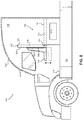
- Figure 1 illustrates a truck cab 100 having a truck cab housing 102 mounted on a truck chassis 104.
- a truck cab interior 106 of the truck cab 100 includes a convertible seat assembly 108 convertible between a seating configuration and a sleeping configuration.
- the convertible seat assembly 108 comprises a base 110 having a substantially flat upper surface 112. In this embodiment, the base 110 is fixed with respect to a floor 114 of the truck cab interior 106.
- the convertible seat assembly 108 further comprises a seat sub-assembly 116 rotatably coupled to the base 110 via a hinge 118 for rotation between the sleeping configuration and the seating configuration.
- the seat sub-assembly 116 comprises a back member 120 having a first side 122 and a second side 124, the first side 122 having a substantially flat surface, and a seat member 128 coupled to the second side of the back member 120.
- the substantially flat surface of the first side 122 of the seat sub-assembly 116 and the substantially flat upper surface 112 of the base 110 form a substantially flat horizontal sleeping surface 130 for at least one person.
- the seat member 128 of the seat sub-assembly 116 forms a seating region 132 for at least one person.
- the hinge 118 in this embodiment includes a bias mechanism 119, which may be a torsion spring, to bias the seat sub-assembly 116 with respect to the base 110.
- the bias mechanism 119 of the hinge 118 biases the seat sub-assembly 116 toward the seating configuration.
- the bias mechanism 119 may bias the seat sub-assembly 116 toward the sleeping configuration.
- the hinge 118 may also include a lock mechanism 133, to secure the hinge 118 selectively in the seating configuration or the sleeping configuration.
- the bias mechanism 119 and the lock mechanism 133 in this example are both part of the hinge 118, but it should be understood that the bias mechanism 119 and lock mechanism 133 may be part of other components, or may be separate components, as desired.
- the lock mechanism 133 is a latch for selectively engaging with a portion of the truck cab interior 106.
- the base 110 includes a base support 134 secured to the floor 114 of the truck cab interior 106.
- the base support 134 may be permanently or removably secured to the floor 114 as desired.
- the base support 134 may also provide one or more storage compartments, such as a drawer 136.
- the seating region 132 is forward-facing, a forward end 138 of the truck cab interior 106 being partially defined by the location of a dashboard 140 and front windshield 141.
- the dashboard 140 includes a steering wheel 142 on the driver-side, and a driver's seat 144 positioned laterally opposite the seating region 132 on the passenger side of the truck cab interior 106.
- the vertical orientation of the seat sub-assembly 116 portion in the seating configuration allows access to the passenger-side door (not illustrated).
- the position of the convertible seat assembly lateral to the driver's seat provides a relatively large rear storage area 146 behind the driver's seat 144.
- the rear storage area 146 is bounded longitudinally by the driver's seat 144 and a rear wall 148 of the truck cab interior 106, and is bounded laterally by the base 110 and a side wall 150 of the truck cab interior 106.
- the side wall 150 may also include one or more side windows 151 and one or more cab doors (not shown) of the truck cab housing 102.
- the rear storage area 146 may include one or more storage compartments, such as, for example, a rear storage compartment 152 secured to the rear wall 148, a side storage compartment 154 secured to the side wall 150, and/or a corner storage compartment 156 secured to one or more of the rear wall 148 and the side wall 150.
- the arrangement of the storage compartments 152, 154, 156 in the rear storage area 146 may be customized based on manufacturer or user preference.
- the base support 134 includes a front wall providing a vertical base support stop 158
- the seat member 128 includes a seat bottom providing a complementary seat member stop 160.
- the seat member stop 160 is horizontal when the seat sub-assembly 116 is in the seating configuration.
- the seat member stop 160 abuts the vertical base support stop 158 when the seat sub-assembly 116 is in the sleeping configuration. This allows the seat member 128, which has a rigid structure in this embodiment, to provide support for the back member 120 extending longitudinally forward from the base 110.
- the upper surface 112 of the base 110 and the horizontal sleeping surface 130 of the seat sub-assembly 116 are substantially horizontally coplanar with each other, so as to provide a combined support surface suitable for a mattress (not shown) or other cushioning arrangement.
- the back member 120 of the seat sub-assembly 116 is rotated substantially 90 degrees between the seating configuration and the sleeping configuration. It should be understood, however, that other configurations are contemplated in which the back member 120 of the seat sub-assembly 116 is rotated more or less than 90 degrees between the seating configuration and the sleeping configuration.
- Figure 4 illustrates an alternative convertible seat assembly 108' having a seat sub-assembly that rotates 180 degrees between the seating configuration and the sleeping configuration.
- the back member 120' of the convertible seat assembly 108' in the seating configuration is completely folded over the base 110', so that the first side 122' of the back member 120' is facing and substantially parallel to the substantially flat upper surface 112' of the base 110'.
- the seat member 128' may be coupled to or integral with the second side 124' of the base 110' to form the seating region 132'.
- Figure 5 illustrates a stowable seat support leg 162 that may be mounted by a hinge 164 to the seat member 128 and rotated between a stowed and a deployed position.
- the seat support leg 162 when deployed, extends vertically from the hinge 164 to the floor 114 of the truck cab interior 106, to provide additional support for the seat member 128 when the seat sub-assembly 116 is in the seating configuration.
- the seat support leg 162 can be rotated about the hinge 164 and stowed in a recess 166 within the seat member 128.
- the seat member 128 is a separate component that is fixed with respect to the back member 120, but it should be understood that other configurations are contemplated.
- the seat member 128 and the back member 120 may be formed as a single component.
- the seat member 128 may be movable with respect to the back member 120.
- Figure 6 illustrates a vertical adjustment mechanism 168 that is coupled between the back member 120 and the seat member 128 of the seat sub-assembly 116.
- the vertical adjustment mechanism 168 which is a selectively movable rail in this example, allows the seat member 128 to be selectively moved to any of a plurality of vertical positions along the back member 120 of the seat sub-assembly 116, as desired.
- FIG. 7 illustrates a sleeping surface support leg 170 rotatably connected to the back member 120 by a hinge 172.
- the sleeping surface support leg 170 may be rotated about the hinge 172 so that the sleeping surface support leg 170 extends vertically between the back member 120 and the floor 114 of the truck cab interior 106, to provide additional support for the seat sub-assembly 116.
- the sleeping surface support leg 170 can be stowed within the back member 120 when not in use by rotating the sleeping surface support leg 170 about the hinge 172 into a recess 174 in the back member 120.
- the seat sub-assembly 116 may also be supported by other components within the truck cab interior 106.
- Figure 8 illustrates a dashboard support member 176 extending horizontally from the dashboard 140.
- the dashboard support member 176 illustrated here as a ledge extending from the dashboard 140, engages and supports a complementary sleeping surface engagement portion 178 of the seat sub-assembly 116 when the seat sub-assembly 116 is in the sleeping configuration.
- the sleeping surface engagement portion 178 which may be an end of the back member 120, rests on and is supported by the dashboard support member 176 to maintain the horizontal sleeping surface 130 of the back member 120 substantially horizontally coplanar with the upper surface 112 of the base 110 when the seat sub-assembly 116 is in the sleeping configuration.
- Figure 9 illustrates a forward-facing incliner member 180 rotatably connected to the base 110 by a hinge 182.
- the forward-facing incliner member 180 may be selectively rotatable between a horizontal sleeping configuration and one or more inclined configurations, which allow the user to rest on the base 110 in a number of recliner positions.
- a stowable tray 184 is provided for use by a user resting against the forward-facing incliner member 180.
- the stowable tray 184 includes a tray member 186 having a fold-out extension member 188 connected to the tray member 186 by a hinge 190. When not in use, the stowable tray 184 may be stowed vertically against or within the side wall 150.
- a stowable display screen sub-assembly 192 may also be provided, which is rotatable from a stowed position substantially parallel to the side wall 150, to a deployed position via a hinge 194.
- a display arm 196 supports a display screen 198 which is rotatable about a hinge 200 to orient the display screen 198 towards a field of view of a user reclining on the base 110 and the forward-facing incliner member 180.
- FIG. 10 an alternative rear-facing incliner member 202 is illustrated.
- the rear-facing incliner member 202 is rotatable about a hinge 204 with respect to the back member 120 of the seat sub-assembly 116.
- a stowable display screen sub-assembly 206 includes an extension member 208 and display screen 210 rotatable between a stowed position and a deployed position about a hinge 212. In the deployed position, the display screen 210 is oriented towards a field of view of a rear facing user reclining on the back member 120 and the rear-facing incliner member 202 of the seat sub-assembly 116.
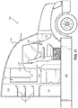
- Figure 11 illustrates a side view of the rear storage area 146 disposed between the driver's seat 144 and the rear wall 148 of the truck cab interior 106.
- the storage compartments 152 and 154 may include a number of different storage sub-compartments 214 and/or shelves 216, as desired.
- one or more storage compartments (corner storage compartment 156 in this example) may be substituted with different components.
- a desk 218 is provided in the corner of the rear storage area 146 between the rear storage compartment 152 and side storage compartment 154.
- a small movable chair or stool 220 may be stowed underneath the desk 218 when not in use, and may be pulled out for use by a user as needed.
- one or more of the storage compartments 152, 154, 156 may be substituted with other components, such as a shower, sink, or another component (not shown).
- the method 300 comprises fixing a base member, such as the base 110 of Figure 1 above, having a substantially flat upper surface in a vehicle interior (Block 302).
- the method 300 further comprises rotatably coupling a seat sub-assembly, such as the back member 120 or the seat sub-assembly 116 of Figure 1 above, to the base member (Block 304).
- the seat sub-assembly is rotatable between a sleeping configuration and a seating configuration, such that a user can selectively rotate the seat sub-assembly from the sleeping configuration to the seating configuration (Block 306), and rotate the seat sub-assembly from the seating configuration to the sleeping configuration (Block 308).
- the seat sub-assembly of the method 300 also comprises a back member and a seat member coupled thereto.
- the back member has a substantially flat first side and a second side.
- the substantially flat surface of the first side of the seat sub-assembly and the substantially flat upper surface of the base member form a substantially flat horizontal sleeping surface for at least one person.
- the seat member of the seat sub-assembly forms a seating region for at least one person.
Landscapes
- Engineering & Computer Science (AREA)
- Transportation (AREA)
- Mechanical Engineering (AREA)
- Aviation & Aerospace Engineering (AREA)
- Health & Medical Sciences (AREA)
- Public Health (AREA)
- Manufacturing & Machinery (AREA)
- Chemical & Material Sciences (AREA)
- Combustion & Propulsion (AREA)
- Seats For Vehicles (AREA)
Description
- Embodiments include a truck cab comprising a convertible seat assembly.
- Many commercial vehicles, such as semi-trucks, include a sleeping area within a vehicle cab, for use by one or more vehicle operators. These vehicle cabs are often referred to as sleeper cabs. Conventional sleeper cabs may include a sleeping surface, such as a cot or mattress assembly, disposed laterally, i.e., extending side-to-side, behind the driver and passenger seats of the cab. While convenient for a vehicle operator, the sleeping surface can take up the entire space behind the seats of the cab, and does not allow for any other use of that space. Accordingly, there is a need for a sleeper cab that uses the space within the cab more efficiently.
-
US 5658046 discloses a seat assembly for a vehicle, comprising a horizontal seat bottom portion and a seat back pivotal between an upright seating position and a horizontal folded position. -
EP 2743183 discloses a cabin attendant seat comprising a backrest movable between an upright position and a folded-back position in which the seat forms an emergency stretcher. -
US 9073608 -
US 2007/0158986 discloses another adjustable seating system for marine vessels. - Embodiments include a truck cab comprising a convertible seat assembly having a sleeping configuration and a seating configuration according to claim 1. In one embodiment, the convertible seat assembly comprises a back member rotatably coupled to a substantially flat base member. The back member has a first side with a substantially flat surface and second side with a seat member coupled thereto. The back member is rotatable between the sleeping configuration and the seating configuration. In the sleeping configuration, the substantially flat first side of the back member and the substantially flat base member form a substantially flat horizontal sleeping surface. In the seating configuration, the seat member is positioned to provide a seating region. One advantage of this arrangement is that a sleeping surface can be oriented longitudinally, i.e., front-to-back, along one side of the truck cab, e.g., a passenger-side, leaving a rear storage area available behind the driver's seat, which can be used for storage, work, or other activities.
- According to one embodiment, the convertible seat assembly comprises a base member having a substantially flat upper surface. The convertible seat assembly further comprises a back member having a first side with a substantially flat surface and a second side, the back member rotatably coupled to the base member for movement between a sleeping configuration and a seating configuration. The convertible seat assembly further comprises a seat member coupled to the second side of the back member. The first side of the back member in the sleeping configuration and the substantially flat upper surface of the base member form a substantially flat horizontal sleeping surface. The seat member in the seating configuration forms a seating region.
- The truck cab comprises a truck cab housing comprising a truck cab interior. The truck cab further comprises a convertible seat assembly. The convertible seat assembly comprises a base member having a substantially flat upper surface, the base member fixed with respect to the truck cab interior. The convertible seat assembly further comprises a back member having a first side with a substantially flat surface and a second side, the back member rotatably coupled to the base member for movement between a sleeping configuration and a seating configuration. The convertible seat assembly further comprises a seat member coupled to the second side of the back member. In the sleeping configuration, the substantially flat surface of the first side of the back member and the substantially flat upper surface of the base member form a substantially flat horizontal sleeping surface. The seat member in the seating configuration forms a seating region.
- A non-claimed method of installing a convertible seat assembly for a truck cab comprises fixing a base member having a substantially flat upper surface in a vehicle interior. The method further comprises rotatably coupling a back member to the base member, the back member having a first side with a substantially flat surface and a second side with a seat member coupled thereto, the back member rotatable between a sleeping configuration and a seating configuration. The substantially flat surface of the first side of the back member in the sleeping configuration and the substantially flat upper surface of the base member form a substantially flat horizontal sleeping surface for at least one person. The seat member in the seating configuration forms a seating region for at least one person.
- Those skilled in the art will appreciate the scope of the present disclosure and realize additional aspects thereof after reading the following detailed description of the preferred embodiments in association with the accompanying drawing figures.
- The accompanying drawing figures incorporated in and forming a part of this specification illustrate several aspects of the disclosure, and together with the description serve to explain the principles of the disclosure.
-
Figure 1 illustrates a truck cab having a seat assembly that is convertible between a sleeping configuration and a seating configuration, according to an embodiment with a non-claimed alternative of a dashboard; -
Figures 2A and2B illustrate side and top views of the truck cab and convertible seat assembly ofFigure 1 in the seating configuration; -
Figures 3A and3B illustrate side and top views of the truck cab and convertible seat assembly ofFigure 1 in the sleeping configuration; -
Figure 4 illustrates a convertible seat assembly similar to the convertible seat assembly ofFigure 1 , wherein the seat assembly is rotatable 180 degrees between the sleeping configuration and the seating configuration, according to an alternative embodiment; -
Figure 5 illustrates the convertible seat assembly ofFigure 1 having one or more stowable seat support legs, according to an embodiment; -
Figure 6 illustrates the convertible seat assembly ofFigure 1 having an adjustment mechanism for moving a seat member with respect to a back member of the seat assembly; -
Figure 7 illustrates the convertible seat assembly ofFigure 1 having one or more stowable sleeping surface support legs, according to an embodiment; -
Figure 8 illustrates the convertible seat assembly ofFigure 1 having a dashboard and a dashboard support member for supporting the seat assembly in the sleeping configuration, according to the invention; -
Figure 9 illustrates the convertible seat assembly ofFigure 1 having a forward-facing incliner member for supporting a user, according to an embodiment; -
Figure 10 illustrates the convertible seat assembly ofFigure 1 having a rear-facing incliner member for supporting a user, according to an embodiment; -
Figure 11 illustrates a side view of a rear storage area showing additional details thereof, according to an embodiment; -
Figure 12 illustrates a top view of the rear storage area showing alternative features thereof, according to an embodiment; and -
Figure 13 is a flowchart of a non-claimed method of installing a convertible seat assembly similar to the convertible seat assembly ofFigure 1 . - The embodiments set forth below represent the necessary information to enable those skilled in the art to practice the embodiments and illustrate the best mode of practicing the embodiments. Upon reading the following description in light of the accompanying drawing figures, those skilled in the art will understand the concepts of the disclosure and will recognize applications of these concepts not particularly addressed herein. It should be understood that these concepts and applications fall within the scope of the disclosure and the accompanying claims.
- It will be understood that, although the terms first, second, etc. may be used herein to describe various elements, these elements should not be limited by these terms. These terms are only used to distinguish one element from another. For example, a first element could be termed a second element, and, similarly, a second element could be termed a first element, without departing from the scope of the present disclosure. As used herein, the term "and/or" includes any and all combinations of one or more of the associated listed items.
- It will be understood that when an element such as a layer, region, or substrate is referred to as being "on" or extending "onto" another element, it can be directly on or extend directly onto the other element or intervening elements may also be present. In contrast, when an element is referred to as being "directly on" or extending "directly onto" another element, there are no intervening elements present. Likewise, it will be understood that when an element such as a layer, region, or substrate is referred to as being "over" or extending "over" another element, it can be directly over or extend directly over the other element or intervening elements may also be present. In contrast, when an element is referred to as being "directly over" or extending "directly over" another element, there are no intervening elements present. It will also be understood that when an element is referred to as being "connected" or "coupled" to another element, it can be directly connected or coupled to the other element or intervening elements may be present. In contrast, when an element is referred to as being "directly connected" or "directly coupled" to another element, there are no intervening elements present.
- Relative terms such as "below" or "above" or "upper" or "lower" or "horizontal" or "vertical" may be used herein to describe a relationship of one element, layer, or region to another element, layer, or region as illustrated in the Figures. It will be understood that these terms and those discussed above are intended to encompass different orientations of the device in addition to the orientation depicted in the Figures.
- The terminology used herein is for the purpose of describing particular embodiments only and is not intended to be limiting of the disclosure. As used herein, the singular forms "a," "an," and "the" are intended to include the plural forms as well, unless the context clearly indicates otherwise. It will be further understood that the terms "comprises," "comprising," "includes," and/or "including" when used herein specify the presence of stated features, integers, steps, operations, elements, and/or components, but do not preclude the presence or addition of one or more other features, integers, steps, operations, elements, components, and/or groups thereof.
- Unless otherwise defined, all terms (including technical and scientific terms) used herein have the same meaning as commonly understood by one of ordinary skill in the art to which this disclosure belongs. It will be further understood that terms used herein should be interpreted as having a meaning that is consistent with their meaning in the context of this specification and the relevant art and will not be interpreted in an idealized or overly formal sense unless expressly so defined herein.
- Embodiments include a seat assembly, and more particularly a convertible seat assembly for a truck cab having a sleeping configuration and a seating configuration. In one embodiment, the convertible seat assembly comprises a back member rotatably coupled to a substantially flat base member. The back member has a first side with a substantially flat surface and second side with a seat member coupled thereto. The back member is rotatable between the sleeping configuration and the seating configuration. In the sleeping configuration, the substantially flat first side of the back member and the substantially flat base member form a substantially flat horizontal sleeping surface. In the seating configuration, the seat member is positioned to provide a seating region. One advantage of this arrangement is that a sleeping surface can be oriented longitudinally, i.e., front-to-back, along one side of the truck cab, e.g., a passenger-side, leaving a rear storage area available behind the driver's seat, which can be used for storage, work, or other activities.
- In this regard,
Figure 1 illustrates atruck cab 100 having atruck cab housing 102 mounted on atruck chassis 104. Atruck cab interior 106 of thetruck cab 100 includes aconvertible seat assembly 108 convertible between a seating configuration and a sleeping configuration. Theconvertible seat assembly 108 comprises a base 110 having a substantially flatupper surface 112. In this embodiment, thebase 110 is fixed with respect to afloor 114 of thetruck cab interior 106. Theconvertible seat assembly 108 further comprises aseat sub-assembly 116 rotatably coupled to thebase 110 via ahinge 118 for rotation between the sleeping configuration and the seating configuration. Theseat sub-assembly 116 comprises aback member 120 having afirst side 122 and asecond side 124, thefirst side 122 having a substantially flat surface, and aseat member 128 coupled to the second side of theback member 120. In the sleeping configuration, the substantially flat surface of thefirst side 122 of theseat sub-assembly 116 and the substantially flatupper surface 112 of the base 110 form a substantially flathorizontal sleeping surface 130 for at least one person. In the seating configuration, theseat member 128 of theseat sub-assembly 116 forms aseating region 132 for at least one person. - The
hinge 118 in this embodiment includes abias mechanism 119, which may be a torsion spring, to bias theseat sub-assembly 116 with respect to thebase 110. In this embodiment, thebias mechanism 119 of thehinge 118 biases theseat sub-assembly 116 toward the seating configuration. Alternatively, thebias mechanism 119 may bias theseat sub-assembly 116 toward the sleeping configuration. Thehinge 118 may also include alock mechanism 133, to secure thehinge 118 selectively in the seating configuration or the sleeping configuration. Thebias mechanism 119 and thelock mechanism 133 in this example are both part of thehinge 118, but it should be understood that thebias mechanism 119 andlock mechanism 133 may be part of other components, or may be separate components, as desired. For example, in this embodiment, thelock mechanism 133 is a latch for selectively engaging with a portion of thetruck cab interior 106. - Referring now to
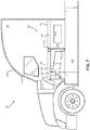
Figures 2A and2B , side and top views of thetruck cab 100 are illustrated to show details of theconvertible seat assembly 108 and other components of thetruck cab housing 102. In this regard, thebase 110 includes abase support 134 secured to thefloor 114 of thetruck cab interior 106. Thebase support 134 may be permanently or removably secured to thefloor 114 as desired. Thebase support 134 may also provide one or more storage compartments, such as adrawer 136. - In this embodiment, in the seating configuration, the
seating region 132 is forward-facing, aforward end 138 of thetruck cab interior 106 being partially defined by the location of adashboard 140 andfront windshield 141. As can be seen inFigure 2B , thedashboard 140 includes asteering wheel 142 on the driver-side, and a driver'sseat 144 positioned laterally opposite theseating region 132 on the passenger side of thetruck cab interior 106. The vertical orientation of theseat sub-assembly 116 portion in the seating configuration allows access to the passenger-side door (not illustrated). In addition, the position of the convertible seat assembly lateral to the driver's seat provides a relatively largerear storage area 146 behind the driver'sseat 144. Therear storage area 146 is bounded longitudinally by the driver'sseat 144 and arear wall 148 of thetruck cab interior 106, and is bounded laterally by thebase 110 and aside wall 150 of thetruck cab interior 106. As shown inFigure 2B , theside wall 150 may also include one ormore side windows 151 and one or more cab doors (not shown) of thetruck cab housing 102. In this embodiment, therear storage area 146 may include one or more storage compartments, such as, for example, arear storage compartment 152 secured to therear wall 148, aside storage compartment 154 secured to theside wall 150, and/or acorner storage compartment 156 secured to one or more of therear wall 148 and theside wall 150. As will be discussed in greater detail with respect toFigures 10 and11 , the arrangement of the storage compartments 152, 154, 156 in therear storage area 146 may be customized based on manufacturer or user preference. - As shown in
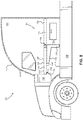
Figure 2A , thebase support 134 includes a front wall providing a verticalbase support stop 158, and theseat member 128 includes a seat bottom providing a complementaryseat member stop 160. The seat member stop 160 is horizontal when theseat sub-assembly 116 is in the seating configuration. Referring now toFigures 3A and3B , the seat member stop 160 abuts the vertical base support stop 158 when theseat sub-assembly 116 is in the sleeping configuration. This allows theseat member 128, which has a rigid structure in this embodiment, to provide support for theback member 120 extending longitudinally forward from thebase 110. In this manner, theupper surface 112 of thebase 110 and thehorizontal sleeping surface 130 of theseat sub-assembly 116 are substantially horizontally coplanar with each other, so as to provide a combined support surface suitable for a mattress (not shown) or other cushioning arrangement. - In this embodiment, the
back member 120 of theseat sub-assembly 116 is rotated substantially 90 degrees between the seating configuration and the sleeping configuration. It should be understood, however, that other configurations are contemplated in which theback member 120 of theseat sub-assembly 116 is rotated more or less than 90 degrees between the seating configuration and the sleeping configuration.Figure 4 illustrates an alternative convertible seat assembly 108' having a seat sub-assembly that rotates 180 degrees between the seating configuration and the sleeping configuration. In this example, the back member 120' of the convertible seat assembly 108' in the seating configuration is completely folded over the base 110', so that the first side 122' of the back member 120' is facing and substantially parallel to the substantially flat upper surface 112' of the base 110'. In this embodiment, the seat member 128' may be coupled to or integral with the second side 124' of the base 110' to form the seating region 132'. - It should be understood that other components may be used to support the seat sub-assembly, such as
seat sub-assembly 116, in the seating configuration and/or in the sleeping configuration, as desired. In this regard,Figure 5 illustrates a stowableseat support leg 162 that may be mounted by ahinge 164 to theseat member 128 and rotated between a stowed and a deployed position. Theseat support leg 162, when deployed, extends vertically from thehinge 164 to thefloor 114 of thetruck cab interior 106, to provide additional support for theseat member 128 when theseat sub-assembly 116 is in the seating configuration. When transitioning theseat sub-assembly 116 to the sleeping configuration, theseat support leg 162 can be rotated about thehinge 164 and stowed in arecess 166 within theseat member 128. - In this embodiment, the
seat member 128 is a separate component that is fixed with respect to theback member 120, but it should be understood that other configurations are contemplated. For example, in one embodiment, theseat member 128 and theback member 120 may be formed as a single component. In an alternative embodiment, theseat member 128 may be movable with respect to theback member 120.Figure 6 illustrates avertical adjustment mechanism 168 that is coupled between theback member 120 and theseat member 128 of theseat sub-assembly 116. Thevertical adjustment mechanism 168, which is a selectively movable rail in this example, allows theseat member 128 to be selectively moved to any of a plurality of vertical positions along theback member 120 of theseat sub-assembly 116, as desired. - Additional supports for the
seat sub-assembly 116 may also be provided when theseat sub-assembly 116 is in the sleeping configuration. In this regard,Figure 7 illustrates a sleeping surface support leg 170 rotatably connected to theback member 120 by ahinge 172. When theseat sub-assembly 116 is in the sleeping configuration, the sleeping surface support leg 170 may be rotated about thehinge 172 so that the sleeping surface support leg 170 extends vertically between theback member 120 and thefloor 114 of thetruck cab interior 106, to provide additional support for theseat sub-assembly 116. Similar to theseat support leg 162 ofFigure 5 , the sleeping surface support leg 170 can be stowed within theback member 120 when not in use by rotating the sleeping surface support leg 170 about thehinge 172 into a recess 174 in theback member 120. - The
seat sub-assembly 116 may also be supported by other components within thetruck cab interior 106.Figure 8 illustrates adashboard support member 176 extending horizontally from thedashboard 140. Thedashboard support member 176, illustrated here as a ledge extending from thedashboard 140, engages and supports a complementary sleepingsurface engagement portion 178 of theseat sub-assembly 116 when theseat sub-assembly 116 is in the sleeping configuration. The sleepingsurface engagement portion 178, which may be an end of theback member 120, rests on and is supported by thedashboard support member 176 to maintain thehorizontal sleeping surface 130 of theback member 120 substantially horizontally coplanar with theupper surface 112 of the base 110 when theseat sub-assembly 116 is in the sleeping configuration. - Additional features may also be provided to enhance the comfort of the user of the
convertible seat assembly 108. In this regard,Figure 9 illustrates a forward-facingincliner member 180 rotatably connected to thebase 110 by ahinge 182. The forward-facingincliner member 180 may be selectively rotatable between a horizontal sleeping configuration and one or more inclined configurations, which allow the user to rest on the base 110 in a number of recliner positions. In this embodiment, astowable tray 184 is provided for use by a user resting against the forward-facingincliner member 180. Thestowable tray 184 includes atray member 186 having a fold-outextension member 188 connected to thetray member 186 by ahinge 190. When not in use, thestowable tray 184 may be stowed vertically against or within theside wall 150. - A stowable
display screen sub-assembly 192 may also be provided, which is rotatable from a stowed position substantially parallel to theside wall 150, to a deployed position via ahinge 194. A display arm 196 supports adisplay screen 198 which is rotatable about ahinge 200 to orient thedisplay screen 198 towards a field of view of a user reclining on thebase 110 and the forward-facingincliner member 180. - Referring now to
Figure 10 , an alternative rear-facingincliner member 202 is illustrated. The rear-facingincliner member 202 is rotatable about ahinge 204 with respect to theback member 120 of theseat sub-assembly 116. In this embodiment, a stowabledisplay screen sub-assembly 206 includes anextension member 208 anddisplay screen 210 rotatable between a stowed position and a deployed position about ahinge 212. In the deployed position, thedisplay screen 210 is oriented towards a field of view of a rear facing user reclining on theback member 120 and the rear-facingincliner member 202 of theseat sub-assembly 116. -
Figure 11 illustrates a side view of therear storage area 146 disposed between the driver'sseat 144 and therear wall 148 of thetruck cab interior 106. In this embodiment, the storage compartments 152 and 154 may include a number ofdifferent storage sub-compartments 214 and/orshelves 216, as desired. As shown byFigure 12 , in addition, one or more storage compartments (corner storage compartment 156 in this example) may be substituted with different components. In this example, adesk 218 is provided in the corner of therear storage area 146 between therear storage compartment 152 andside storage compartment 154. A small movable chair orstool 220 may be stowed underneath thedesk 218 when not in use, and may be pulled out for use by a user as needed. In another embodiment, one or more of the storage compartments 152, 154, 156 may be substituted with other components, such as a shower, sink, or another component (not shown). - Referring now to
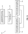
Figure 13 , a flowchart of anon-claimed method 300 of installing a convertible seat assembly for a truck cab, such as theconvertible seat assembly 108 ofFigure 1 above, is illustrated. Themethod 300 comprises fixing a base member, such as thebase 110 ofFigure 1 above, having a substantially flat upper surface in a vehicle interior (Block 302). Themethod 300 further comprises rotatably coupling a seat sub-assembly, such as theback member 120 or theseat sub-assembly 116 ofFigure 1 above, to the base member (Block 304). As with the embodiment ofFigure 1 above, the seat sub-assembly is rotatable between a sleeping configuration and a seating configuration, such that a user can selectively rotate the seat sub-assembly from the sleeping configuration to the seating configuration (Block 306), and rotate the seat sub-assembly from the seating configuration to the sleeping configuration (Block 308). - As with the embodiment of
Figure 1 above, the seat sub-assembly of themethod 300 also comprises a back member and a seat member coupled thereto. The back member has a substantially flat first side and a second side. In the sleeping configuration, the substantially flat surface of the first side of the seat sub-assembly and the substantially flat upper surface of the base member form a substantially flat horizontal sleeping surface for at least one person. In the seating configuration, the seat member of the seat sub-assembly forms a seating region for at least one person. - Those skilled in the art will recognize modifications to the preferred embodiments of the present disclosure. All such modifications are considered within the scope of the claims that follow.
Claims (12)
- A truck cab (100)(100), comprising:a truck cab housing (102) comprising a truck cab interior (106);a convertible seat assembly (108, 108') comprising:a base member (110, 110') having a substantially flat upper surface (112, 112'), the base member (110, 110') fixed with respect to the truck cab interior (106);a back member (120, 120') having a first side (122, 122') with a substantially flat surface and a second side (124, 124'), the back member (120, 120') rotatably coupled to the base member (110, 110') for movement between a sleeping configuration and a seating configuration; anda seat member (128, 128') coupled to the second side (124, 124') of the back member (120, 120');wherein the substantially flat surface of the first side (122, 122') of the back member (120, 120') in the sleeping configuration and the substantially flat upper surface (112, 112') of the base member (110, 110') form a substantially flat horizontal sleeping surface (130, 130'),wherein the seat member (128, 128') in the seating configuration forms a seating region (132, 132'), andcharacterised in thatthe truck cab interior (106) further comprises a dashboard support member (176) supporting the back member (120, 120') in the sleeping configuration.
- The truck cab (100) of claim 1, further comprising a rotatable hinge (118, 118') coupled between the base member (110, 110') and the back member (120, 120').
- The truck cab (100) of claim 2, further comprising a bias mechanism coupled to the rotatable hinge (118, 118') to bias the back member (120, 120') toward one of the sleeping configuration or the seating configuration.
- The truck cab (100) of claim 1, further comprising a leg member (162) movable between a stowed configuration when the back member (120, 120') is in the sleeping configuration and a deployed configuration supporting the seat member (128, 128') in the seating configuration.
- The truck cab (100) of claim 1, further comprising a leg member (170) movable between a stowed configuration when the back member (120, 120') is in the seating configuration and a deployed configuration supporting the back member (120, 120') in the sleeping configuration.
- The truck cab (100) of claim 1, further comprising a lock mechanism (133) for selectively securing the back member (120, 120') in the sleeping configuration or the seating configuration, preferably wherein the lock mechanism (133) comprises a latch for selectively engaging with a portion of an interior of the truck cab (106) to secure the back member (120, 120') in at least one of the sleeping configuration or the seating configuration.
- The truck cab (100) of claim 1, wherein the base member (110) further comprises a stop (158) that engages a stop (160) formed on the back member (120, 120') for supporting the back member (120, 120') in the sleeping configuration.
- The truck cab (100) of claim 1, wherein the back member (120, 120') and the seat member (128, 128') in the seating configuration form a forward facing seat with respect to the truck cab interior (106).
- The truck cab (100) of claim 1, wherein the truck cab interior (106) comprises a driver-side seat and wherein the back member (120, 120') and the seat member (128, 128') in the seating configuration form a passenger-side seat laterally opposite the driver-side seat.
- The truck cab (100) of claim 9, wherein the substantially flat horizontal sleeping surface (130, 130') in the sleeping configuration extends longitudinally between a forward portion of the truck cab interior (106) and a rear portion of the truck cab interior (106).
- The truck cab (100) of claim 10, wherein the back member (120, 120') and the seat member (128, 128') in the seating configuration form a forward facing seat with respect to the truck cab interior (106).
- The truck cab (100) of claim 10, wherein the driver-side seat (144) and the base member (110, 110') define a storage area (146) in the truck cab interior (106).
Applications Claiming Priority (1)
| Application Number | Priority Date | Filing Date | Title |
|---|---|---|---|
| PCT/US2016/066066 WO2018111217A1 (en) | 2016-12-12 | 2016-12-12 | Convertible seat assembly for a truck cab |
Publications (3)
| Publication Number | Publication Date |
|---|---|
| EP3551498A1 EP3551498A1 (en) | 2019-10-16 |
| EP3551498A4 EP3551498A4 (en) | 2020-07-15 |
| EP3551498B1 true EP3551498B1 (en) | 2021-09-22 |
Family
ID=62559082
Family Applications (1)
| Application Number | Title | Priority Date | Filing Date |
|---|---|---|---|
| EP16924058.7A Active EP3551498B1 (en) | 2016-12-12 | 2016-12-12 | Convertible seat assembly for a truck cab |
Country Status (4)
| Country | Link |
|---|---|
| US (1) | US10913385B2 (en) |
| EP (1) | EP3551498B1 (en) |
| CN (1) | CN110023139B (en) |
| WO (1) | WO2018111217A1 (en) |
Families Citing this family (4)
| Publication number | Priority date | Publication date | Assignee | Title |
|---|---|---|---|---|
| US20210309132A1 (en) * | 2020-04-02 | 2021-10-07 | Andras Plank S. | Vehicular Camp and Method |
| RU206740U1 (en) * | 2021-04-28 | 2021-09-24 | Публичное акционерное общество "КАМАЗ" | Sleeping place of the vehicle cabin |
| US12408776B2 (en) | 2021-11-23 | 2025-09-09 | Sleep Right Products Llc | Foldable bed |
| USD1019207S1 (en) * | 2021-11-23 | 2024-03-26 | Presto Day Bed, LLC | Foldable vehicle bed |
Family Cites Families (50)
| Publication number | Priority date | Publication date | Assignee | Title |
|---|---|---|---|---|
| US1367013A (en) * | 1919-02-11 | 1921-02-01 | Bradshaw Richard | Combined bed and seat |
| US1387083A (en) * | 1920-04-01 | 1921-08-09 | Lorenzo B Welch | Convertible seat for automobiles |
| US2504769A (en) * | 1945-12-07 | 1950-04-18 | Budd Co | Sleeping car arrangement |
| US2564512A (en) * | 1947-03-21 | 1951-08-14 | Henry E Specht | Combination bed and table for trailers |
| US2953103A (en) * | 1957-10-31 | 1960-09-20 | Pullman Co | Combination coach and sleeping car |
| US2993529A (en) * | 1960-01-25 | 1961-07-25 | D Mar Mfg Company Inc | Folding bunk seat for boats |
| DE1430921A1 (en) * | 1964-07-17 | 1968-12-12 | Daimler Benz Ag | Driver's cab for vehicles with at least one passenger couch |
| US3473840A (en) * | 1967-05-18 | 1969-10-21 | Cleve Zane Miles | Vehicle seat convertible to a bed or couch |
| US3879081A (en) * | 1973-09-17 | 1975-04-22 | Int Harvester Co | Motor truck cab conversion to a sleeper |
| US3910626A (en) * | 1974-08-14 | 1975-10-07 | Ryder Truck Rental Inc | Convertible seat for sleeper cab |
| FR2487653A1 (en) * | 1980-07-31 | 1982-02-05 | Chausson Usines Sa | TRANSFORMABLE SEAT |
| US5425516A (en) * | 1994-07-01 | 1995-06-20 | Daines; Paul H. | Aircraft passenger accomodation system |
| US5954398A (en) | 1996-03-14 | 1999-09-21 | Mitsubishi Jidosha Kogyo Kabushiki Kaisha | Seat structure for motor vehicle |
| US5658046A (en) * | 1996-01-16 | 1997-08-19 | Lear Corporation | Vehicle seat trim cover attachment strip |
| GB9706650D0 (en) * | 1997-04-02 | 1997-05-21 | Virgin Atlantic Airways Ltd | A seat |
| US6129404A (en) * | 1997-12-23 | 2000-10-10 | Chrysler Corporation | Seat arrangement for a vehicle |
| US6367839B1 (en) * | 1999-03-05 | 2002-04-09 | Volvo Trucks North America, Inc. | Padded bunk restraint |
| US6102463A (en) * | 1999-05-18 | 2000-08-15 | Delphi Technologies, Inc. | Vehicle seat assembly with hidden storage compartment |
| US6899379B1 (en) * | 1999-10-22 | 2005-05-31 | Mack Trucks, Inc. | Modular sleeping compartment for trucks |
| ATE417779T1 (en) | 1999-10-22 | 2009-01-15 | Mack Trucks | MODULAR SLEEP CABIN FOR TRUCKS |
| SE518291C2 (en) * | 2000-08-04 | 2002-09-17 | Volvo Lastvagnar Ab | Chair and bed combination |
| AUPR539401A0 (en) * | 2001-05-31 | 2001-06-28 | Blazely, Ann Marie | Position adjustable bed assembly |
| ATE363409T1 (en) * | 2001-08-09 | 2007-06-15 | Virgin Atlantic Airways Ltd | A SEATING ARRANGEMENT AND A PASSENGER ACCOMMODATION UNIT FOR A VEHICLE |
| GB2384464B (en) | 2002-01-25 | 2004-11-10 | Primera Consultancy And Design | A bulkhead for a van |
| US6711762B2 (en) * | 2002-01-30 | 2004-03-30 | Ktk Services, Inc. | Method of using a truck cab bridge bed |
| JP2003341398A (en) * | 2002-05-23 | 2003-12-03 | Honda Motor Co Ltd | Vehicle seat arrangement structure |
| US6837531B2 (en) * | 2002-07-24 | 2005-01-04 | Daimlerchrysler Corporation | Flip seat arrangement having upper seat back pivot |
| JP3706093B2 (en) * | 2002-09-04 | 2005-10-12 | 本田技研工業株式会社 | Rear structure of the vehicle |
| US6644724B1 (en) * | 2002-10-29 | 2003-11-11 | International Truck Intellectual Property Company, Llc | Compactable extended cab modular bunk assembly |
| WO2007001276A1 (en) * | 2005-06-22 | 2007-01-04 | Mack Trucks, Inc. | Truck with cab having longitudinally oriented bunk |
| EP1759991A1 (en) * | 2005-08-31 | 2007-03-07 | Lufthansa Technik AG | Arrangement for seating and lying down |
| US7934762B2 (en) * | 2005-12-13 | 2011-05-03 | Mack Trucks, Inc. | Vehicle with sleeping arrangement |
| US20070158986A1 (en) | 2005-12-22 | 2007-07-12 | Porter, Inc. D/B/A Thunderbird Products | Adjustable sun lounge |
| WO2007098614A1 (en) * | 2006-03-03 | 2007-09-07 | Schukra Of North America, Ltd. | Fold flat seating |
| USD556467S1 (en) * | 2006-08-24 | 2007-12-04 | International Truck Intellectual Property Company, Llc | Crescent couch and bunk of a truck vehicle |
| JP2009292405A (en) * | 2008-06-09 | 2009-12-17 | Toyota Boshoku Corp | Vehicular seat |
| DE102008053961A1 (en) | 2008-10-30 | 2010-05-06 | Daimler Ag | Seat for use in driving cab of lorry, has backrest part moved from seating position into reclining position, and reclining part held at backrest part, where reclining part is movable between stowed position and reclining position |
| JP5690737B2 (en) * | 2008-11-01 | 2015-03-25 | ジョンソン コントロールズ テクノロジー カンパニーJohnson Controls Technology Company | Folding seat |
| DE102010054090A1 (en) * | 2010-12-10 | 2011-07-28 | Daimler AG, 70327 | Seat system for use in driver's cabin of lorry, has seat part hingedly connected with backrest part, base part held at and hingedly connected with seat part, and backrest part held at guide device in upper region in height adjustable manner |
| DE112011105252T5 (en) * | 2011-05-18 | 2014-02-13 | Volvo Lastvagnar Ab | Driver's cab for a heavy-duty truck |
| US8468626B2 (en) * | 2011-10-21 | 2013-06-25 | Ralph Carrier | Cab sleeper |
| CN104520187B (en) * | 2012-05-04 | 2017-04-05 | 庞巴迪公司 | Seat unit that converts into a bunk bed |
| EP2743183A1 (en) | 2012-12-14 | 2014-06-18 | Airbus Operations GmbH | Convertible cabin attendant seat |
| US20150034580A1 (en) * | 2013-07-30 | 2015-02-05 | Henrik Hofvander | Modular Storage in Passenger Compartments |
| US9073608B1 (en) | 2013-07-30 | 2015-07-07 | Boston Whaler, Inc. | Multi-position lounge seat for marine vessels |
| WO2015097630A1 (en) * | 2013-12-27 | 2015-07-02 | Bombardier Inc. | Aircraft divan convertible into a bed |
| JP6254873B2 (en) * | 2014-02-25 | 2017-12-27 | 島田商事株式会社 | In-car equipment that can be used as a cargo bed or bed in a car |
| DE202014009092U1 (en) * | 2014-11-17 | 2016-02-18 | Adalbert Bandemer | Compact slide-out sleeping area for campers and caravans |
| CN107000797B (en) * | 2014-12-17 | 2019-04-30 | 沃尔沃卡车集团 | Adjustable berths and vehicles equipped with the same |
| US9809140B2 (en) * | 2016-02-02 | 2017-11-07 | Notel Enterprise LLC | Platform system for vehicle interior |
-
2016
- 2016-12-12 CN CN201680091250.8A patent/CN110023139B/en not_active Expired - Fee Related
- 2016-12-12 US US16/468,322 patent/US10913385B2/en active Active
- 2016-12-12 WO PCT/US2016/066066 patent/WO2018111217A1/en not_active Ceased
- 2016-12-12 EP EP16924058.7A patent/EP3551498B1/en active Active
Also Published As
| Publication number | Publication date |
|---|---|
| EP3551498A4 (en) | 2020-07-15 |
| CN110023139A (en) | 2019-07-16 |
| CN110023139B (en) | 2022-07-08 |
| US20190299840A1 (en) | 2019-10-03 |
| WO2018111217A1 (en) | 2018-06-21 |
| US10913385B2 (en) | 2021-02-09 |
| EP3551498A1 (en) | 2019-10-16 |
Similar Documents
| Publication | Publication Date | Title |
|---|---|---|
| US9187012B2 (en) | Pivoting and reclining vehicle seating assembly | |
| US7735895B2 (en) | Seat configuration system for an automotive interior | |
| US8625034B2 (en) | Seatback entertainment display system | |
| US9016749B2 (en) | Collapsible rear seat storage assembly | |
| US7677656B2 (en) | Modular seat/console for a vehicle | |
| US7980617B2 (en) | Vehicle seat with back-support and shoulder-support wings | |
| EP3551498B1 (en) | Convertible seat assembly for a truck cab | |
| US20070096496A1 (en) | Vehicle seat that tips and kneels and folds into a stowage well | |
| US6767040B1 (en) | Independent back slide and stow | |
| US20130082478A1 (en) | Adjustable floating seat | |
| US10730444B2 (en) | Vehicle seating arrangement having storage solutions | |
| CN101104388A (en) | car rear seat equipment | |
| US10906444B2 (en) | Multi-function connectivity module | |
| US20130082500A1 (en) | Flip-up floating seat | |
| US10144331B2 (en) | Seat with integrated table | |
| US7484786B2 (en) | Adjustable rear seat | |
| US12103441B2 (en) | Vehicle seat | |
| US20100102942A1 (en) | Interior Fitting for a Motor Vehicle | |
| CN112109608B (en) | Folding storage seat and automobile | |
| US9840176B1 (en) | Seat with integrated foldable table | |
| JP2003104103A (en) | Driver's cabin of useful vehicle | |
| JP2025173916A (en) | Vehicle-mounted deck unit | |
| US20070290530A1 (en) | Seat Recliner Bench for Motor Homes or the Like | |
| JP2004217073A (en) | Vehicle bed structure | |
| KR20080071389A (en) | Especially for the passenger compartment of an industrial vehicle, the driver's cab and the driver's cab equipped with the auxiliary seat |
Legal Events
| Date | Code | Title | Description |
|---|---|---|---|
| STAA | Information on the status of an ep patent application or granted ep patent |
Free format text: STATUS: THE INTERNATIONAL PUBLICATION HAS BEEN MADE |
|
| PUAI | Public reference made under article 153(3) epc to a published international application that has entered the european phase |
Free format text: ORIGINAL CODE: 0009012 |
|
| STAA | Information on the status of an ep patent application or granted ep patent |
Free format text: STATUS: REQUEST FOR EXAMINATION WAS MADE |
|
| 17P | Request for examination filed |
Effective date: 20190618 |
|
| AK | Designated contracting states |
Kind code of ref document: A1 Designated state(s): AL AT BE BG CH CY CZ DE DK EE ES FI FR GB GR HR HU IE IS IT LI LT LU LV MC MK MT NL NO PL PT RO RS SE SI SK SM TR |
|
| AX | Request for extension of the european patent |
Extension state: BA ME |
|
| DAV | Request for validation of the european patent (deleted) | ||
| DAX | Request for extension of the european patent (deleted) | ||
| A4 | Supplementary search report drawn up and despatched |
Effective date: 20200617 |
|
| RIC1 | Information provided on ipc code assigned before grant |
Ipc: B60P 3/39 20060101AFI20200610BHEP Ipc: B60N 2/34 20060101ALI20200610BHEP Ipc: B60N 2/30 20060101ALI20200610BHEP |
|
| GRAP | Despatch of communication of intention to grant a patent |
Free format text: ORIGINAL CODE: EPIDOSNIGR1 |
|
| STAA | Information on the status of an ep patent application or granted ep patent |
Free format text: STATUS: GRANT OF PATENT IS INTENDED |
|
| RIC1 | Information provided on ipc code assigned before grant |
Ipc: B60N 2/34 20060101ALI20210409BHEP Ipc: B60N 2/30 20060101ALI20210409BHEP Ipc: B60P 3/39 20060101AFI20210409BHEP |
|
| INTG | Intention to grant announced |
Effective date: 20210429 |
|
| GRAS | Grant fee paid |
Free format text: ORIGINAL CODE: EPIDOSNIGR3 |
|
| GRAA | (expected) grant |
Free format text: ORIGINAL CODE: 0009210 |
|
| STAA | Information on the status of an ep patent application or granted ep patent |
Free format text: STATUS: THE PATENT HAS BEEN GRANTED |
|
| AK | Designated contracting states |
Kind code of ref document: B1 Designated state(s): AL AT BE BG CH CY CZ DE DK EE ES FI FR GB GR HR HU IE IS IT LI LT LU LV MC MK MT NL NO PL PT RO RS SE SI SK SM TR |
|
| REG | Reference to a national code |
Ref country code: GB Ref legal event code: FG4D |
|
| REG | Reference to a national code |
Ref country code: DE Ref legal event code: R096 Ref document number: 602016064197 Country of ref document: DE |
|
| REG | Reference to a national code |
Ref country code: IE Ref legal event code: FG4D |
|
| REG | Reference to a national code |
Ref country code: CH Ref legal event code: EP Ref country code: AT Ref legal event code: REF Ref document number: 1432083 Country of ref document: AT Kind code of ref document: T Effective date: 20211015 |
|
| REG | Reference to a national code |
Ref country code: LT Ref legal event code: MG9D |
|
| REG | Reference to a national code |
Ref country code: NL Ref legal event code: MP Effective date: 20210922 |
|
| PG25 | Lapsed in a contracting state [announced via postgrant information from national office to epo] |
Ref country code: HR Free format text: LAPSE BECAUSE OF FAILURE TO SUBMIT A TRANSLATION OF THE DESCRIPTION OR TO PAY THE FEE WITHIN THE PRESCRIBED TIME-LIMIT Effective date: 20210922 Ref country code: FI Free format text: LAPSE BECAUSE OF FAILURE TO SUBMIT A TRANSLATION OF THE DESCRIPTION OR TO PAY THE FEE WITHIN THE PRESCRIBED TIME-LIMIT Effective date: 20210922 Ref country code: NO Free format text: LAPSE BECAUSE OF FAILURE TO SUBMIT A TRANSLATION OF THE DESCRIPTION OR TO PAY THE FEE WITHIN THE PRESCRIBED TIME-LIMIT Effective date: 20211222 Ref country code: LT Free format text: LAPSE BECAUSE OF FAILURE TO SUBMIT A TRANSLATION OF THE DESCRIPTION OR TO PAY THE FEE WITHIN THE PRESCRIBED TIME-LIMIT Effective date: 20210922 Ref country code: BG Free format text: LAPSE BECAUSE OF FAILURE TO SUBMIT A TRANSLATION OF THE DESCRIPTION OR TO PAY THE FEE WITHIN THE PRESCRIBED TIME-LIMIT Effective date: 20211222 Ref country code: RS Free format text: LAPSE BECAUSE OF FAILURE TO SUBMIT A TRANSLATION OF THE DESCRIPTION OR TO PAY THE FEE WITHIN THE PRESCRIBED TIME-LIMIT Effective date: 20210922 Ref country code: SE Free format text: LAPSE BECAUSE OF FAILURE TO SUBMIT A TRANSLATION OF THE DESCRIPTION OR TO PAY THE FEE WITHIN THE PRESCRIBED TIME-LIMIT Effective date: 20210922 |
|
| REG | Reference to a national code |
Ref country code: AT Ref legal event code: MK05 Ref document number: 1432083 Country of ref document: AT Kind code of ref document: T Effective date: 20210922 |
|
| PG25 | Lapsed in a contracting state [announced via postgrant information from national office to epo] |
Ref country code: LV Free format text: LAPSE BECAUSE OF FAILURE TO SUBMIT A TRANSLATION OF THE DESCRIPTION OR TO PAY THE FEE WITHIN THE PRESCRIBED TIME-LIMIT Effective date: 20210922 Ref country code: GR Free format text: LAPSE BECAUSE OF FAILURE TO SUBMIT A TRANSLATION OF THE DESCRIPTION OR TO PAY THE FEE WITHIN THE PRESCRIBED TIME-LIMIT Effective date: 20211223 |
|
| PG25 | Lapsed in a contracting state [announced via postgrant information from national office to epo] |
Ref country code: AT Free format text: LAPSE BECAUSE OF FAILURE TO SUBMIT A TRANSLATION OF THE DESCRIPTION OR TO PAY THE FEE WITHIN THE PRESCRIBED TIME-LIMIT Effective date: 20210922 |
|
| PG25 | Lapsed in a contracting state [announced via postgrant information from national office to epo] |
Ref country code: IS Free format text: LAPSE BECAUSE OF FAILURE TO SUBMIT A TRANSLATION OF THE DESCRIPTION OR TO PAY THE FEE WITHIN THE PRESCRIBED TIME-LIMIT Effective date: 20220122 Ref country code: SK Free format text: LAPSE BECAUSE OF FAILURE TO SUBMIT A TRANSLATION OF THE DESCRIPTION OR TO PAY THE FEE WITHIN THE PRESCRIBED TIME-LIMIT Effective date: 20210922 Ref country code: RO Free format text: LAPSE BECAUSE OF FAILURE TO SUBMIT A TRANSLATION OF THE DESCRIPTION OR TO PAY THE FEE WITHIN THE PRESCRIBED TIME-LIMIT Effective date: 20210922 Ref country code: PT Free format text: LAPSE BECAUSE OF FAILURE TO SUBMIT A TRANSLATION OF THE DESCRIPTION OR TO PAY THE FEE WITHIN THE PRESCRIBED TIME-LIMIT Effective date: 20220124 Ref country code: PL Free format text: LAPSE BECAUSE OF FAILURE TO SUBMIT A TRANSLATION OF THE DESCRIPTION OR TO PAY THE FEE WITHIN THE PRESCRIBED TIME-LIMIT Effective date: 20210922 Ref country code: NL Free format text: LAPSE BECAUSE OF FAILURE TO SUBMIT A TRANSLATION OF THE DESCRIPTION OR TO PAY THE FEE WITHIN THE PRESCRIBED TIME-LIMIT Effective date: 20210922 Ref country code: ES Free format text: LAPSE BECAUSE OF FAILURE TO SUBMIT A TRANSLATION OF THE DESCRIPTION OR TO PAY THE FEE WITHIN THE PRESCRIBED TIME-LIMIT Effective date: 20210922 Ref country code: EE Free format text: LAPSE BECAUSE OF FAILURE TO SUBMIT A TRANSLATION OF THE DESCRIPTION OR TO PAY THE FEE WITHIN THE PRESCRIBED TIME-LIMIT Effective date: 20210922 Ref country code: CZ Free format text: LAPSE BECAUSE OF FAILURE TO SUBMIT A TRANSLATION OF THE DESCRIPTION OR TO PAY THE FEE WITHIN THE PRESCRIBED TIME-LIMIT Effective date: 20210922 Ref country code: AL Free format text: LAPSE BECAUSE OF FAILURE TO SUBMIT A TRANSLATION OF THE DESCRIPTION OR TO PAY THE FEE WITHIN THE PRESCRIBED TIME-LIMIT Effective date: 20210922 |
|
| REG | Reference to a national code |
Ref country code: DE Ref legal event code: R097 Ref document number: 602016064197 Country of ref document: DE |
|
| PG25 | Lapsed in a contracting state [announced via postgrant information from national office to epo] |
Ref country code: MC Free format text: LAPSE BECAUSE OF FAILURE TO SUBMIT A TRANSLATION OF THE DESCRIPTION OR TO PAY THE FEE WITHIN THE PRESCRIBED TIME-LIMIT Effective date: 20210922 Ref country code: DK Free format text: LAPSE BECAUSE OF FAILURE TO SUBMIT A TRANSLATION OF THE DESCRIPTION OR TO PAY THE FEE WITHIN THE PRESCRIBED TIME-LIMIT Effective date: 20210922 |
|
| PLBE | No opposition filed within time limit |
Free format text: ORIGINAL CODE: 0009261 |
|
| REG | Reference to a national code |
Ref country code: CH Ref legal event code: PL |
|
| STAA | Information on the status of an ep patent application or granted ep patent |
Free format text: STATUS: NO OPPOSITION FILED WITHIN TIME LIMIT |
|
| GBPC | Gb: european patent ceased through non-payment of renewal fee |
Effective date: 20211222 |
|
| 26N | No opposition filed |
Effective date: 20220623 |
|
| REG | Reference to a national code |
Ref country code: BE Ref legal event code: MM Effective date: 20211231 |
|
| PG25 | Lapsed in a contracting state [announced via postgrant information from national office to epo] |
Ref country code: LU Free format text: LAPSE BECAUSE OF NON-PAYMENT OF DUE FEES Effective date: 20211212 Ref country code: IE Free format text: LAPSE BECAUSE OF NON-PAYMENT OF DUE FEES Effective date: 20211212 Ref country code: GB Free format text: LAPSE BECAUSE OF NON-PAYMENT OF DUE FEES Effective date: 20211222 |
|
| PG25 | Lapsed in a contracting state [announced via postgrant information from national office to epo] |
Ref country code: SI Free format text: LAPSE BECAUSE OF FAILURE TO SUBMIT A TRANSLATION OF THE DESCRIPTION OR TO PAY THE FEE WITHIN THE PRESCRIBED TIME-LIMIT Effective date: 20210922 Ref country code: BE Free format text: LAPSE BECAUSE OF NON-PAYMENT OF DUE FEES Effective date: 20211231 |
|
| PG25 | Lapsed in a contracting state [announced via postgrant information from national office to epo] |
Ref country code: LI Free format text: LAPSE BECAUSE OF NON-PAYMENT OF DUE FEES Effective date: 20211231 Ref country code: CH Free format text: LAPSE BECAUSE OF NON-PAYMENT OF DUE FEES Effective date: 20211231 |
|
| PG25 | Lapsed in a contracting state [announced via postgrant information from national office to epo] |
Ref country code: IT Free format text: LAPSE BECAUSE OF FAILURE TO SUBMIT A TRANSLATION OF THE DESCRIPTION OR TO PAY THE FEE WITHIN THE PRESCRIBED TIME-LIMIT Effective date: 20210922 |
|
| PG25 | Lapsed in a contracting state [announced via postgrant information from national office to epo] |
Ref country code: CY Free format text: LAPSE BECAUSE OF FAILURE TO SUBMIT A TRANSLATION OF THE DESCRIPTION OR TO PAY THE FEE WITHIN THE PRESCRIBED TIME-LIMIT Effective date: 20210922 |
|
| PG25 | Lapsed in a contracting state [announced via postgrant information from national office to epo] |
Ref country code: SM Free format text: LAPSE BECAUSE OF FAILURE TO SUBMIT A TRANSLATION OF THE DESCRIPTION OR TO PAY THE FEE WITHIN THE PRESCRIBED TIME-LIMIT Effective date: 20210922 Ref country code: HU Free format text: LAPSE BECAUSE OF FAILURE TO SUBMIT A TRANSLATION OF THE DESCRIPTION OR TO PAY THE FEE WITHIN THE PRESCRIBED TIME-LIMIT; INVALID AB INITIO Effective date: 20161212 |
|
| PG25 | Lapsed in a contracting state [announced via postgrant information from national office to epo] |
Ref country code: MK Free format text: LAPSE BECAUSE OF FAILURE TO SUBMIT A TRANSLATION OF THE DESCRIPTION OR TO PAY THE FEE WITHIN THE PRESCRIBED TIME-LIMIT Effective date: 20210922 |
|
| PG25 | Lapsed in a contracting state [announced via postgrant information from national office to epo] |
Ref country code: MT Free format text: LAPSE BECAUSE OF FAILURE TO SUBMIT A TRANSLATION OF THE DESCRIPTION OR TO PAY THE FEE WITHIN THE PRESCRIBED TIME-LIMIT Effective date: 20210922 |
|
| PGFP | Annual fee paid to national office [announced via postgrant information from national office to epo] |
Ref country code: FR Payment date: 20241227 Year of fee payment: 9 |
|
| PGFP | Annual fee paid to national office [announced via postgrant information from national office to epo] |
Ref country code: DE Payment date: 20241227 Year of fee payment: 9 |
|
| PG25 | Lapsed in a contracting state [announced via postgrant information from national office to epo] |
Ref country code: TR Free format text: LAPSE BECAUSE OF FAILURE TO SUBMIT A TRANSLATION OF THE DESCRIPTION OR TO PAY THE FEE WITHIN THE PRESCRIBED TIME-LIMIT Effective date: 20210922 |