EP2410623A2 - Deflector module and system for tensioning a conductor strand on high voltage masts - Google Patents
Deflector module and system for tensioning a conductor strand on high voltage masts Download PDFInfo
- Publication number
- EP2410623A2 EP2410623A2 EP11005633A EP11005633A EP2410623A2 EP 2410623 A2 EP2410623 A2 EP 2410623A2 EP 11005633 A EP11005633 A EP 11005633A EP 11005633 A EP11005633 A EP 11005633A EP 2410623 A2 EP2410623 A2 EP 2410623A2
- Authority
- EP
- European Patent Office
- Prior art keywords
- deflection
- module
- conductor
- mast
- voltage
- Prior art date
- Legal status (The legal status is an assumption and is not a legal conclusion. Google has not performed a legal analysis and makes no representation as to the accuracy of the status listed.)
- Withdrawn
Links
Images

Classifications
-
- H—ELECTRICITY
- H02—GENERATION; CONVERSION OR DISTRIBUTION OF ELECTRIC POWER
- H02G—INSTALLATION OF ELECTRIC CABLES OR LINES, OR OF COMBINED OPTICAL AND ELECTRIC CABLES OR LINES
- H02G1/00—Methods or apparatus specially adapted for installing, maintaining, repairing or dismantling electric cables or lines
- H02G1/02—Methods or apparatus specially adapted for installing, maintaining, repairing or dismantling electric cables or lines for overhead lines or cables
- H02G1/04—Methods or apparatus specially adapted for installing, maintaining, repairing or dismantling electric cables or lines for overhead lines or cables for mounting or stretching
Definitions
- the invention relates to a deflection module for a high-voltage conductor cable and a system for tensioning a conductor cable on high voltage pylons.
- high voltage power lines for example, for a voltage of 110kV or 380kV
- conductor cables are stretched between high-voltage masts, which - depending on the voltage level - have a distance of, for example, 100m to 400m.
- the ladder cables are connected by hanging insulators to the traverses of the high voltage masts.
- Power supply systems are usually three-phase, i. a ladder system consists of three individual ladders.
- a ladder system consists of three individual ladders.
- several conductor systems - in some cases also different voltage levels - are often mounted on a single mast.
- there is a ground wire which is led over the tips of the respective high voltage masts and which serves as lightning protection.
- An overhead line has to reduce the skin effect usually a plurality of layers of twisted conductors, wherein in the interior of the conductor to increase the tensile force, a steel core is woven and the surrounding conductor layers made of aluminum. Due to this structure of a conductor cable is especially during transport and assembly, make sure that it is not bent too much, otherwise damage to the rope would occur. As a rough guideline, it can be assumed that the minimum bending radius of the conductor does not fall below its 30-fold radius.
- a conductor As a multi-strand system, i. several parallel e.g. in a square with 30cm - 50cm edge length and provided with spacers arranged conductor cables are electrically connected in parallel, resulting in a ladder system of 3 phases already 12 individual conductors. This makes it particularly difficult to construct such an overhead line because according to the prior art each conductor cable is pulled individually onto the high-voltage mast.
- high-voltage masts are usually designed only as a support poles, which are not able to take on their hanging insulators horizontally acting on the ladder cable forces.
- Tie-down masts which can also intercept horizontal forces of the conductors due to their insulator arrangement, are usually provided only at a very large distance from each other. In order not to let these horizontal forces during the clamping process to be too large, it is either necessary to arrange the role with the exciting overhead line at a very large distance from the high voltage mast, for example, at a distance greater 120m.
- a deflection module for a high-voltage conductor cable, comprising an arcuate deflection channel, which is so pronounced that a conductor cable can be guided in this along its extension, a module holder with connection device, which is provided for releasably connected to a high voltage mast be and a spacer element through which a mechanically rigid connection between the deflection channel and module holder is formed.
- the idea according to the invention here is to make the high-voltage mast, by means of which the conductor cable is to be tensioned, fit to a guy mast by temporary installation of deflection modules so that its separate erection is eliminated.
- the designed as a support pole high-voltage mast as such is quite able to absorb horizontal forces, it is only the hanging insulator, which is not able by its hanging attachment to a single point of the crossmember of the mast, acting on the conductor rope carried by him horizontal forces intercept.
- This is effected according to the invention of the deflection modules to be mounted on the high-voltage mast. After the tensioning of the desired conductor cables, the deflection modules must then be removed again from the high-voltage mast.
- a deflection module initially has a deflection channel for the conductor cable to be clamped. This is necessary in order to be able to guide the conductor cable from the foot of the high-voltage mast to the desired position in the upper area.
- the deflection channel is to be designed such that the conductor cable along the Umlenkkanals is movable relative to the high-voltage mast. This allows pulling of the rope through the deflection channel.
- the deflection channel is also designed to execute in a radius of curvature, by which an excessive bending of the conductor cable is avoided. A bend of about 90 ° in a deflection channel is to be regarded as a typical size, which allows a particularly flexible cable guide along the high-voltage mast.
- the module holder with connecting device serves to establish a temporary and non-positive connection with the high-voltage mast.
- This can be, for example, a screw, clamp and / or plug connection, which are particularly easy to detach again.
- high voltage masts are usually designed as a grid structures with a variety of struts.
- a strut can namely be particularly easily enclosed by a connecting element in its diameter, so that a simple and secure connection can be realized.
- several connection points of a module holder with the high-voltage mast are possible, so as to realize a particularly stable connection.
- the spacer element serves to ensure a distance from the high-voltage mast to the deflection channel and thus to prevent possible contact with the tensioned conductor cable with the high-voltage mast.
- the deflection channel is at least partially formed by a respective segment portion of a freely rotatable roller with grooved recess for guiding the conductor along its circumference.
- a movement of a conductor cable through the deflecting channel formed at least in sections from the groove-shaped recess can be realized in a particularly simple and low-friction manner by a rotational movement of the roller. Even if, during a rotational movement of the roller, there is no relative movement to a conductor cable guided over the roller, this is to be regarded as movement of the conductor cable through a deflection channel.
- a plurality of freely rotatable rollers arranged parallel in a common plane and along an arc are provided, so that along the arc a polygon-like deflection channel is formed for a conductor cable.
- a plurality of deflection channels arranged in parallel are provided. This allows in particular the synchronous pulling of several conductors each through one of the deflection channels.
- the parallelism of the deflection channels is helpful in particular for the parallel guidance of several conductor cables from the ladder cable rollers to be provided on the mast base into the upper area of the mast, where the ropes are then inserted into the desired clamping positions.
- the spacer element is adaptable, so that a selectable distance and / or a selectable orientation of the deflection channel to the module holder can be realized.
- the desired conductor cable guide from the foot of the high-voltage mast in the upper region requires namely the arrangement of the deflection of the deflection modules at specific positions relative to the mast.
- the module holder of the deflection can only on the high-voltage mast, and this in particular on the lattice struts, mount, which sometimes only a certain, but not ideal for the conductor guide position or orientation is possible.
- a lockable telescopic extension of a spacer element or even a lockable rotary joint are devices that allow a correspondingly high flexibility in the installation of the deflection or in the conductor cable guide. But also the fixed mounting of additional intermediate, extension or kink pieces in the spacer achieved the same purpose.
- the first deflection module is arranged on the high-voltage mast that the first end of the Umlenkkanals the first Umlenkmoduls is aligned in the imaginary extension of the exciting conductor in its desired position on the high voltage mast and the second end of the Umlenkkanals preferably in vertical orientation.
- the conductor rope to be tensioned coming from the conductor pulley is first introduced vertically into the second end of the deflection channel, where it is deflected by approximately 90 ° and then at the first end of the Umlenkkanals in the pulling direction something in front of the insulator, which is to carry the ladder cable on the mast, executed approximately in a horizontal direction.
- the conductor cable is then pulled with the desired sag to the adjacent high-voltage mast to the corresponding comparable position.
- further deflection modules are arranged on the high-voltage mast in such a way that a conductor cable subjected to a tensile force can be guided mastnah from the foot of the high-voltage mast to a traverse located in the upper region and from there along the traverse to the second end of the deflection channel of the first deflection module is.
- the arrangement of the further deflection modules ensures a cable guide from the foot of the high-voltage mast to the first deflection module. This is very dependent on the shape of the mast.
- a deflecting module at the foot of the high-voltage mast may initially make sense in order to divert the conductor cable, which has been unwound horizontally from the conductor pulley, into a mast-proximate vertical.
- a further deflection module is to be provided, which guides the conductor cable into the outer region of the traverse.
- a deflection module is to be provided there, which feeds the conductor cable from the vertical direction, ie from above or below, to the first deflection module.
- deflection modules are provided with a plurality of parallel deflection channels, so that a plurality of conductor cables interconnected at their respective one end can be pulled together via the deflection modules.
- the conductors to be pulled synchronously are connected at their one end to a common connecting blade.
- the conductor cables are fastened in preferably equidistant spacing, which is adapted to the distances between the parallel deflection channels.
- a pull rope is centrally connected, with which the sword and the conductor cables can be pulled over the deflection modules.
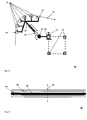
- Fig. 1 shows an exemplary system 10 for tensioning a conductor cable, in the illustrated variant for synchronously tensioning four conductor cables 28 on a mast 20, which for example has a height of 30m - 70m.
- the mast has two trusses 22, 24, wherein the four to exciting conductor cables 28 are to form a connected phase conductor of a 3-phase system and to be held at the outer end of the crossbar 24 by an insulator, not shown.
- the four ladder ropes are unwound and provided by a respective conductor pulley, as indicated by the reference numeral 26.
- the four conductor cables 28 are deflected close to the mast in an approximately vertical direction and guided in the upper mast area to the mounted there third deflection module 16, which in turn also has four parallel deflection channels.
- the plane of the four parallel conductors leads to a torsion of about 90 °, as indicated in the drawing.
- the conductor cables are now deflected in an approximately horizontal direction and guided to the left outer edge of the cross member 24 and there deflected a second deflection module 14 in the vertical and the first deflection module 12.
- the respective deflection modules are each connected to the mast 20 or its cross members 22, 24 with module holders and spacer elements, not shown. After tensioning the respective conductor cables, the deflection modules must be removed again.
- All deflection modules 12, 14, 16, 18 are each provided with four deflection channels, one deflection channel being assigned to one conductor cable in each case.
- the deflection channels are indicated in this case as a respective rotatable roller with groove-like depression, which of course, for example, also formed of a plurality of smaller and arranged on a circular path rollers polygon-like deflection channels are used.
- a slight offset of the parallel deflection channels is indicated in order to supply the conductor cables in each case exactly perpendicular to the corresponding deflection channel of the first deflection module 12. But this is not necessarily necessary. It is also conceivable that - as with the deflection modules 12, 16, 18 - all parallel deflection channels are arranged around the same imaginary axis of rotation.
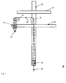
- Fig. 2 shows a first exemplary deflection module 40.
- This includes an arcuate deflection channel, the two ends are indicated by the reference numerals 57 and 58.
- the arcuate deflection channel is polygon similar approximated by a plurality of freely rotatable rollers 42 with groove-like depression, so that the minimum bending radius of the guided through the deflection channel 57-58 conductor cable 56 is not exceeded.
- rollers 42 By using the rollers 42, a movement of the conductor cable through the deflection channel is made possible in a particularly simple and low-friction manner.
- the six in a common plane arranged rotatable rollers 42 are connected via a common holder with a spacer 44 in this example.
- This has for geometrical adaptation to a length-adjustable cylinder 46 which can be locked in the desired length position, for example by a screw connection.
- the length-adjustable cylinder 46 in turn is connected at its opposite end with a device for adjusting the orientation, for example a ball joint with locking device.
- the two latter devices are optional components of the spacer element 44, which allow increased flexibility in the arrangement of the deflection module 40 on the high voltage mast - in this case on the struts 54 of a traverse.
- the device for adjusting the orientation 48 is connected to a module holder 50, which is non-positively connected to a high-voltage mast or the associated struts 54.
- a U-shaped bracket is provided, which encloses a strut in its cross section and is connected via a locking device releasably connected to a strut 54.
- the deflection module 40 is particularly easy to mount on a mast - also due to its reduced by using several smaller roles - weight - and disassemble again.
- Fig. 3 shows in comparison a roll with a large roller diameter 60, which is at least so large that the minimum bending radius - for example, 0.8 m - of the guided over the roller 62 conductor 68 is not exceeded.
- the roller 62 is rotatable about the axis of rotation 66 and has a groove-like recess 64, which in this case serves in sections as a deflection channel.
- Fig. 4 shows various roll variants with small roll diameter, which can be used to approximate the arc shape of several parallel Umlenkkanälen polygon similar.
- Reference numeral 70a shows four identical individual rollers 72, which are arranged around the same axis of rotation 82 and which guide a conductor cable 80 in a respective groove-like recess 78.
- Reference numeral 70b shows two double or tandem rollers 74, each guiding two conductor cables 80 in corresponding groove-like depressions.
- the reference number 70c shows a single quadrilateral roller 76, which has four groove-like recesses 78, in each of which a conductor cable 78 is guided. This figure illustrates that the assembly cost is advantageously reduced in such multiple roles.
- 2-, 3- or 5-fold variants are conceivable.
- the reference numeral 90 shows a connecting blade 92 with four conductor cables 100 and a pull cable 94.
- the four conductor cables 100 are hinted still guided by a quadruple roller 96 which is rotatable about a rotation axis 98.
- a connecting blade 92 it is particularly advantageous if the leadership of the conductors 100 from the foot of the high-voltage mast to the insertion point in the upper region of the mast, ie in the pulling direction shortly before the insulator, which is to carry the conductor, takes place in mutually parallel planes.
- connection sword 92 can be pulled with the pull cable 94 easily from the lower part of the high-voltage mast on all deflection to the upper part of the high-voltage mast and from there to all other pylons, where it pulls in this case four conductors by itself through all deflection channels.
- connection sword 92 realized, but it could possibly mean a certain additional effort in the leadership of the connection sword in the upper mast area.
Abstract
Description
Die Erfindung betrifft ein Umlenkmodul für ein Hochspannungsleiterseil und ein System zum Spannen eines Leiterseils auf Hochspannungsmasten.The invention relates to a deflection module for a high-voltage conductor cable and a system for tensioning a conductor cable on high voltage pylons.
Es ist allgemein bekannt, dass Hochspannungsleitungen, beispielsweise für eine Spannung von 110kV oder 380kV, üblicherweise als Freileitungen ausgeführt werden. Hierbei sind Leiterseile zwischen Hochspannungsmasten gespannt, welche - je nach Spannungsebene - einen Abstand von beispielsweise 100m bis 400m aufweisen. Die Leiterseile sind durch hängende Isolatoren mit den Traversen der Hochspannungsmaste verbunden. Stromversorgungssysteme sind in aller Regel dreiphasig ausgeführt, d.h. ein Leitersystem besteht aus drei Einzelleitern. Um eine für eine Freileitung benötigte Trasse möglichst optimal auszunutzen, sind häufig mehrere Leitersysteme - teilweise auch unterschiedlicher Spannungsebenen - an einem einzigen Mast montiert. Hinzu kommt noch ein Erdseil, welches über die Spitzen der jeweiligen Hochspannungsmaste geführt ist und welches als Blitzschutz dient.It is well known that high voltage power lines, for example, for a voltage of 110kV or 380kV, are usually designed as overhead lines. In this case, conductor cables are stretched between high-voltage masts, which - depending on the voltage level - have a distance of, for example, 100m to 400m. The ladder cables are connected by hanging insulators to the traverses of the high voltage masts. Power supply systems are usually three-phase, i. a ladder system consists of three individual ladders. In order to make the best possible use of a route required for an overhead line, several conductor systems - in some cases also different voltage levels - are often mounted on a single mast. In addition, there is a ground wire, which is led over the tips of the respective high voltage masts and which serves as lightning protection.
Ein Freileitungsseil weist zur Reduktion des Skineffektes zumeist eine Vielzahl an Lagen von verdrillten Einzelleitern auf, wobei im Inneren des Leiterseils zur Erhöhung der Zugkraft eine Stahlseele eingeflochten ist und die diese umgebenden Leiterlagen aus Aluminium bestehen. Aufgrund dieses Aufbaus eines Leiterseiles ist insbesondere beim Transport und der Montage darauf zu achten, dass es nicht zu stark gebogen wird, weil sonst Beschädigungen des Seils auftreten würden. Als grober Richtwert kann angenommen werden, dass der minimale Biegeradius des Leiterseils nicht dessen 30-fachen Radius unterschreitet.An overhead line has to reduce the skin effect usually a plurality of layers of twisted conductors, wherein in the interior of the conductor to increase the tensile force, a steel core is woven and the surrounding conductor layers made of aluminum. Due to this structure of a conductor cable is especially during transport and assembly, make sure that it is not bent too much, otherwise damage to the rope would occur. As a rough guideline, it can be assumed that the minimum bending radius of the conductor does not fall below its 30-fold radius.
Zur weiteren Reduktion des Skineffektes ist es auch üblich, einen Leiter als mehrseiliges System aufzubauen, d.h. mehrere parallel z.B. in einem Quadrat mit 30cm - 50cm Kantenlänge und mit Abstandhaltern versehene angeordnete Leiterseile sind elektrisch parallel geschaltet, womit sich bei einem Leitersystem von 3 Phasen bereits 12 Einzelleiter ergeben. Dies erschwert in besonderer Weise den Bau einer derartigen Freileitung, weil gemäß dem Stand der Technik jedes Leiterseil einzeln auf den Hochspannungsmast gezogen wird.To further reduce the skin effect, it is also common to construct a conductor as a multi-strand system, i. several parallel e.g. in a square with 30cm - 50cm edge length and provided with spacers arranged conductor cables are electrically connected in parallel, resulting in a ladder system of 3 phases already 12 individual conductors. This makes it particularly difficult to construct such an overhead line because according to the prior art each conductor cable is pulled individually onto the high-voltage mast.
Beim Spannen von Leiterseilen ist ein dünnes Zugseil vorgesehen, welches zuvor manuell längs des angestrebten Verlaufes des Leiterseiles zwischen den Hochspannungsmasten angeordnet wurde und welches an seinem rückwärtigen Ende mit dem zu spannenden und zumeist auf einer Rolle befindlichen Leiterseil verbunden ist. Der Spannvorgang wird durch eine Zugbewegung an dem Zugseil begründet, so dass das Leiterseil entsprechend hinterher gezogen wird und so seine gewünschte Lage an den Hochspannungsmasten einnimmt.When tensioning ladder ropes a thin pull rope is provided, which was previously arranged manually along the desired course of the conductor between the high voltage pylons and which is connected at its rear end to the exciting and usually located on a roll conductor. The clamping operation is justified by a pulling movement on the pull rope, so that the conductor cable is pulled behind accordingly and thus assumes its desired position on the pylons.
Nachteilig ist insbesondere, dass Hochspannungsmaste zumeist nur als Tragmaste ausgeführt sind, welche über ihre hängenden Isolatoren nicht in der Lage sind, horizontal auf das Leiterseil wirkende Kräfte aufzunehmen. Abspannmaste, welche aufgrund ihrer Isolatorenanordnung auch Horizontalkräfte der Leiterseile abfangen können, sind zumeist nur in einem sehr großen Abstand zueinander vorgesehen. Um diese Horizontalkräfte beim Spannvorgang nicht zu groß werden zu lassen, ist es entweder notwendig, die Rolle mit dem zu spannenden Freileitungsseil in einem sehr großen Abstand zum Hochspannungsmast anzuordnen, beispielsweise in einem Abstand größer 120m. Wenn dieser Platz nicht vorhanden ist, was öfters der Fall ist, muss ein behelfsmäßiger Abspannmast in unmittelbarer Nähe des betreffenden Hochspannungsmastes errichtet werden, welcher die horizontal auf den Hochspannungsmast wirkenden Seilkräfte beim Spannvorgang abfängt. Dies ist mit einem unverhältnismäßig hohen Aufwand verbunden.A particular disadvantage is that high-voltage masts are usually designed only as a support poles, which are not able to take on their hanging insulators horizontally acting on the ladder cable forces. Tie-down masts, which can also intercept horizontal forces of the conductors due to their insulator arrangement, are usually provided only at a very large distance from each other. In order not to let these horizontal forces during the clamping process to be too large, it is either necessary to arrange the role with the exciting overhead line at a very large distance from the high voltage mast, for example, at a distance greater 120m. If this space is not available, which is often the case, a makeshift guy pole must be erected in the immediate vicinity of the relevant pylon, which intercepts the rope forces acting horizontally on the pylon during the tensioning process. This is associated with a disproportionate effort.
Ausgehend von diesem Stand der Technik ist es Aufgabe der Erfindung, das Spannen von Leiterseilen für Hochspannungsleitungen zu vereinfachen.Based on this prior art, it is an object of the invention to simplify the tensioning of conductors for power lines.
Diese Aufgabe wird gelöst durch ein erfindungsgemäßes Umlenkmodul für ein Hochspannungsleiterseil, umfassend einen bogenförmigen Umlenkkanal, welcher derart ausgeprägt ist, dass ein Leiterseil in diesem längs seiner Erstreckung beweglich führbar ist, einen Modulhalter mit Verbindungsvorrichtung, welcher dafür vorgesehen ist, lösbar mit einem Hochspannungsmast verbunden zu werden und ein Distanzelement, durch welches eine mechanisch starre Verbindung zwischen Umlenkkanal und Modulhalter gebildet ist.This object is achieved by a deflection module according to the invention for a high-voltage conductor cable, comprising an arcuate deflection channel, which is so pronounced that a conductor cable can be guided in this along its extension, a module holder with connection device, which is provided for releasably connected to a high voltage mast be and a spacer element through which a mechanically rigid connection between the deflection channel and module holder is formed.
Die erfindungsgemäße Idee hierbei besteht darin, den Hochspannungsmast, über den das Leiterseil gespannt werden soll, durch temporäre Montage von Umlenkmodulen zu einem Abspannmast zu ertüchtigen, so dass dessen separate Errichtung entfällt. Der als Tragmast ausgeführte Hochspannungsmast als solcher ist durchaus in der Lage, Horizontalkräfte aufzunehmen, es ist lediglich der hängende Isolator, welcher durch seine hängende Befestigung an einem einzigen Punkt der Traverse des Mastes nicht in der Lage ist, auf das von ihm getragene Leiterseil wirkende Horizontalkräfte abzufangen. Dies wird erfindungsgemäß von den am Hochspannungsmast zu montierenden Umlenkmodulen bewirkt. Nach erfolgtem Spannen der gewünschten Leiterseile sind die Umlenkmodule dann wieder vom Hochspannungsmast zu entfernen.The idea according to the invention here is to make the high-voltage mast, by means of which the conductor cable is to be tensioned, fit to a guy mast by temporary installation of deflection modules so that its separate erection is eliminated. The designed as a support pole high-voltage mast as such is quite able to absorb horizontal forces, it is only the hanging insulator, which is not able by its hanging attachment to a single point of the crossmember of the mast, acting on the conductor rope carried by him horizontal forces intercept. This is effected according to the invention of the deflection modules to be mounted on the high-voltage mast. After the tensioning of the desired conductor cables, the deflection modules must then be removed again from the high-voltage mast.
Ein Umlenkmodul weist zunächst einen Umlenkkanal für das zu spannende Leiterseil auf. Dieser ist nötig, um das Leiterseil vom Fuß des Hochspannungsmastes zu der gewünschten Position im oberen Bereich führen zu können. Hierbei ist der Umlenkkanal derart auszuführen, dass das Leiterseil längs des Umlenkkanals relativ zum Hochspannungsmast bewegbar ist. Hierdurch wird ein Ziehen des Seils durch den Umlenkkanal ermöglicht. Der Umlenkkanal ist zudem in einem Bogenradius auszuführen, durch welchen eine zu starke Biegung des Leiterseils vermieden ist. Eine Biegung von ca. 90° in einem Umlenkkanal ist hierbei als typische Größe anzusehen, welche eine besonders flexible Seilführung längs des Hochspannungsmastes ermöglicht.A deflection module initially has a deflection channel for the conductor cable to be clamped. This is necessary in order to be able to guide the conductor cable from the foot of the high-voltage mast to the desired position in the upper area. Here, the deflection channel is to be designed such that the conductor cable along the Umlenkkanals is movable relative to the high-voltage mast. This allows pulling of the rope through the deflection channel. The deflection channel is also designed to execute in a radius of curvature, by which an excessive bending of the conductor cable is avoided. A bend of about 90 ° in a deflection channel is to be regarded as a typical size, which allows a particularly flexible cable guide along the high-voltage mast.
Der Modulhalter mit Verbindungsvorrichtung dient dazu, eine temporäre und kraftschlüssige Verbindung mit dem Hochspannungsmast herzustellen. Dies kann beispielsweise eine Schraub-, Klemm- und/oder Steckverbindung sein, welche besonders einfach wieder lösbar sind. Hierbei erweist es sich als günstig, dass Hochspannungsmaste zumeist als Gitterkonstruktionen mit einer Vielzahl von Streben ausgeführt sind. Eine Strebe kann nämlich besonders einfach von einem Verbindungselement in ihrem Durchmesser umschlossen werden, so dass eine einfache und sichere Verbindung realisierbar ist. Selbstverständlich sind auch mehrere Verbindungspunkte eines Modulhalters mit dem Hochspannungsmast möglich, um so eine besonders stabile Verbindung zu realisieren.The module holder with connecting device serves to establish a temporary and non-positive connection with the high-voltage mast. This can be, for example, a screw, clamp and / or plug connection, which are particularly easy to detach again. It proves to be beneficial that high voltage masts are usually designed as a grid structures with a variety of struts. A strut can namely be particularly easily enclosed by a connecting element in its diameter, so that a simple and secure connection can be realized. Of course, several connection points of a module holder with the high-voltage mast are possible, so as to realize a particularly stable connection.
Das Distanzelement dient dazu, einen Abstand vom Hochspannungsmast zum Umlenkkanal zu gewährleisten und so ein mögliches Berühren des zu spannenden Leiterseiles mit dem Hochspannungsmast zu verhindern.The spacer element serves to ensure a distance from the high-voltage mast to the deflection channel and thus to prevent possible contact with the tensioned conductor cable with the high-voltage mast.
In einer besonders bevorzugten Ausgestaltung des erfindungsgemäßen Umlenkmoduls ist der Umlenkkanal zumindest abschnittsweise durch einen jeweiligen Segmentabschnitt einer frei drehbaren Rolle mit rillenförmiger Vertiefung zur Führung des Leiterseils längs ihres Umfangs gebildet.In a particularly preferred embodiment of the deflection module according to the invention the deflection channel is at least partially formed by a respective segment portion of a freely rotatable roller with grooved recess for guiding the conductor along its circumference.
Eine Bewegung eines Leiterseils durch den zumindest abschnittsweise aus der rillenförmigen Vertiefung gebildeten Umlenkkanal ist durch eine Drehbewegung der Rolle besonders einfach und reibungsarm realisierbar. Auch wenn bei einer Drehbewegung der Rolle keine Relativbewegung zu einem über die Rolle geführten Leiterseil erfolgt, ist dieses als Bewegung des Leiterseils durch einen Umlenkkanal anzusehen.A movement of a conductor cable through the deflecting channel formed at least in sections from the groove-shaped recess can be realized in a particularly simple and low-friction manner by a rotational movement of the roller. Even if, during a rotational movement of the roller, there is no relative movement to a conductor cable guided over the roller, this is to be regarded as movement of the conductor cable through a deflection channel.
In einer weiteren Ausgestaltung des erfindungsgemäßen Umlenkmoduls sind mehrere parallel in einer gemeinsamen Ebene und längs eines Bogens angeordnete frei drehbare Rollen vorgesehen, so dass längs des Bogens ein polygonähnlicher Umlenkkanal für ein Leiterseil gebildet ist.In a further embodiment of the deflection module according to the invention a plurality of freely rotatable rollers arranged parallel in a common plane and along an arc are provided, so that along the arc a polygon-like deflection channel is formed for a conductor cable.
Durch die Verwendung einer Vielzahl, bogenähnlich angeordneter kleiner Rollen ist im Vergleich zu einer einzigen großen Rolle, welche wenigstens den Mindestdurchmesser von 30 mal dem Leiterseildurchmesser aufweisen muss, um eine Beschädigung des Leiterseils bei Spannvorgang zu vermeiden, eine erhebliche Gewichtseinsparung realisiert. Hierdurch wird die zwangsläufig manuell zu erfolgende Montage der Umlenkmodule am Hochspannungsmast deutlich vereinfacht. Die Approximation des Mindestradius des Umlenkkanals mit einem Rollenpolygon vermeidet in vergleichbarer Weise eine Beschädigung des Leiterseiles bei der Montage, wie ein exakt kreissegmentförmig verlaufender Umlenkkanal desselben Radius. Die Anzahl der Rollen beträgt, je nach zu approximierendem Bogenradius und Rollendurchmesser beispielsweise 3 bis 12, wobei ein kleinerer Rollendurchmesser eine eher erhöhte Zahl an Rollen bedingt.By using a plurality of arcuately arranged small rollers is compared to a single large role, which at least the minimum diameter of 30 times the conductor diameter must have, in order to avoid damage to the conductor cable during clamping, realized a significant weight saving. As a result, the inevitably manually to be carried out mounting the deflection on the high-voltage mast is significantly simplified. The approximation of the minimum radius of the Umlenkkanals with a roller polygon avoids damage to the conductor cable during assembly in a comparable manner, such as an exactly circular segment-shaped deflection of the same radius. The number of rolls is, for example, 3 to 12, depending on the radius of curvature and roll diameter to be approximated, with a smaller roll diameter necessitating a rather increased number of rolls.
Entsprechend einer weiteren erfindungsgemäßen Variante des Umlenkmoduls sind mehrere parallel angeordnete Umlenkkanäle vorgesehen. Dies ermöglicht insbesondere das synchrone Ziehen von mehreren Leiterseilen jeweils durch einen der Umlenkkanäle. Die Parallelität der Umlenkkanäle ist insbesondere für die parallele Führung von mehreren Leiterseilen von den am Mastfuß vorzusehenden Leiterseilenrollen in den oberen Bereich des Mastes hilfreich, wo dann die Einführung der Seile in den gewünschten Spannpositionen erfolgt.According to a further variant of the deflection module according to the invention, a plurality of deflection channels arranged in parallel are provided. This allows in particular the synchronous pulling of several conductors each through one of the deflection channels. The parallelism of the deflection channels is helpful in particular for the parallel guidance of several conductor cables from the ladder cable rollers to be provided on the mast base into the upper area of the mast, where the ropes are then inserted into the desired clamping positions.
In einer besonderen Ausführungsform des erfindungsgemäßen Umlenkmoduls sind längs derselben Drehachse angeordnete frei drehbare Rollen benachbarter Umlenkkanäle durch eine gemeinsame frei drehbare Rolle mit einer entsprechenden Anzahl an parallelen rillenförmiger Vertiefungen substituiert.In a particular embodiment of the deflection module according to the invention arranged along the same axis of rotation freely rotatable rollers adjacent Umlenkkanäle are substituted by a common freely rotatable roller with a corresponding number of parallel groove-shaped recesses.
Hierdurch wird sowohl eine weitere Gewichtseinsparung als auch eine Reduktion der Anzahl der temporär zu montierenden Komponenten erreicht. Zudem ist der Abstand zwischen benachbarten Umlenkkanälen weiter reduzierbar, so dass sich eine vereinfachte Leiterseilführung vom Fuß des Hochspannungsmastes in den oberen Bereich ergibt. Bei mehreren synchron zu führenden Leiterseilen ist zum Beispiel eine Drehung der Ebene der parallel geführten Leiter, beispielsweise um 90°, besonders problemlos zu realisieren, wenn diese möglichst dicht beieinander angeordnet sind. Durch das synchrone Ziehen der einzelnen Leiterseile ist keine freie Drehbarkeit jeder einzelnen Rolle gefordert, so dass durch das Zusammenfassen von Einzelrollen keine Einschränkung der Funktionalität gegeben ist.This achieves both a further weight saving and a reduction in the number of components to be mounted temporarily. In addition, the distance between adjacent Umlenkkanälen is further reduced, so that there is a simplified conductor cable guide from the foot of the high-voltage mast in the upper region. For example, in the case of a plurality of conductor cables that are synchronous with one another, it is particularly easy to realize a rotation of the plane of the conductors routed in parallel, for example by 90 °, if these are arranged as close as possible to one another. Due to the synchronous pulling of the individual conductor cables, no free rotatability of each individual roller is required, so that the combination of individual rollers does not limit the functionality.
Gemäß einer besonders bevorzugten Umlenkmodulvariante ist das Distanzelement anpassbar, so dass ein wählbarer Abstand und/oder eine wählbare Ausrichtung des Umlenkkanals zum Modulhalter realisierbar sind.According to a particularly preferred deflection module variant, the spacer element is adaptable, so that a selectable distance and / or a selectable orientation of the deflection channel to the module holder can be realized.
Dies ermöglicht eine besonders einfache Montage der Umlenkmodule am Mast. Die gewünschte Leiterseilführung vom Fuß des Hochspannungsmastes in dessen oberen Bereich erfordert nämlich die Anordnung der Umlenkkanäle der Umlenkmodule an ganz bestimmten Positionen relativ zum Mast. Andererseits lassen sich die Modulhalter der Umlenkmodule nur am Hochspannungsmast, und dies insbesondere an dessen Gitterstreben, montieren, wobei teilweise auch nur eine bestimmte, aber für die Leiterseilführung nicht ideale Position bzw. Orientierung möglich ist.This allows a particularly simple installation of the deflection on the mast. The desired conductor cable guide from the foot of the high-voltage mast in the upper region requires namely the arrangement of the deflection of the deflection modules at specific positions relative to the mast. On the other hand, the module holder of the deflection can only on the high-voltage mast, and this in particular on the lattice struts, mount, which sometimes only a certain, but not ideal for the conductor guide position or orientation is possible.
Eine feststellbare teleskopähnliche Verlängerung eines Distanzelementes oder aber auch ein arretierbares Drehgelenk sind Vorrichtungen, die eine entsprechend hohe Flexibilität bei der Montage der Umlenkmodule bzw. bei der Leiterseilführung ermöglichen. Aber auch das feste Montieren von zusätzlichen Zwischen-, Verlängerungs- oder Knickstücken in das Distanzelement erreicht denselben Zweck.A lockable telescopic extension of a spacer element or even a lockable rotary joint are devices that allow a correspondingly high flexibility in the installation of the deflection or in the conductor cable guide. But also the fixed mounting of additional intermediate, extension or kink pieces in the spacer achieved the same purpose.
Die Aufgabe wird auch gelöst durch ein System zum Spannen eines Leiterseils auf Hochspannungsmasten, umfassend einen Hochspannungsmast und wenigstens ein erstes mit diesem verbundenes Umlenkmodul nach einem der Ansprüche 1 - 6. Die entsprechenden Vorteile eines solchen Systems wurden bereits eingangs erläutert.The object is also achieved by a system for clamping a conductor cable at high-voltage masts comprising a high-voltage mast and at least a first connected thereto director module according to one of claims 1 - 6 have already been explained at the beginning, the respective advantages of such a system.
In einer weiteren Ausgestaltungsform des erfindungsgemäßen Systems ist das erste Umlenkmodul derart am Hochspannungsmast angeordnet, dass das erste Ende des Umlenkkanals des ersten Umlenkmoduls in der gedachten Verlängerung des zu spannenden Leiterseils in seiner gewünschten Position am Hochspannungsmast ausgerichtet ist und das zweite Ende des Umlenkkanals vorzugsweise in vertikaler Ausrichtung.In a further embodiment of the system according to the invention, the first deflection module is arranged on the high-voltage mast that the first end of the Umlenkkanals the first Umlenkmoduls is aligned in the imaginary extension of the exciting conductor in its desired position on the high voltage mast and the second end of the Umlenkkanals preferably in vertical orientation.
So wird das zu spannende Leiterseil von der Leiterseilrolle kommend zunächst vertikal in das zweite Ende des Umlenkkanals eingeführt, dort etwa um 90° umgelenkt und dann am ersten Ende des Umlenkkanals in Zugrichtung etwas vor dem Isolator, welcher das Leiterseil am Mast tragen soll, in etwa in horizontaler Richtung ausgeführt. Beim weiteren Spannvorgang wird das Leiterseil dann mit dem gewünschten Durchhang zum benachbarten Hochspannungsmast an die entsprechend vergleichbare Position gezogen. Durch diese Anordnung nimmt das erste Umlenkmodul nahezu die gesamte horizontale Zugkraft vom Isolator, womit ein problemloses Spannen des Leiterseils ermöglicht ist.Thus, the conductor rope to be tensioned coming from the conductor pulley is first introduced vertically into the second end of the deflection channel, where it is deflected by approximately 90 ° and then at the first end of the Umlenkkanals in the pulling direction something in front of the insulator, which is to carry the ladder cable on the mast, executed approximately in a horizontal direction. During further clamping operation, the conductor cable is then pulled with the desired sag to the adjacent high-voltage mast to the corresponding comparable position. By this arrangement, the first deflection module takes almost the entire horizontal tensile force from the insulator, whereby a trouble-free clamping of the conductor cable is made possible.
Entsprechend einer weiteren Ausführungsform des erfindungsgemäßen Systems sind weitere Umlenkmodule derart am Hochspannungsmast angeordnet, dass ein mit einer Zugkraft beaufschlagtes Leiterseil vom Fuß des Hochspannungsmastes mastnah zu einer im oberen Bereich befindlichen Traverse und von dort längs der Traverse zum zweiten Ende des Umlenkkanals des ersten Umlenkmoduls beweglich führbar ist.According to a further embodiment of the system according to the invention, further deflection modules are arranged on the high-voltage mast in such a way that a conductor cable subjected to a tensile force can be guided mastnah from the foot of the high-voltage mast to a traverse located in the upper region and from there along the traverse to the second end of the deflection channel of the first deflection module is.
Durch die Anordnung der weiteren Umlenkmodule wird eine Seilführung vom Fuß des Hochspannungsmastes zum ersten Umlenkmodul gewährleistet. Dies ist sehr abhängig von der Form des Mastes. In einer Vielzahl der Fälle dürfte zunächst ein Umlenkmodul am Fuße des Hochspannungsmastes sinnvoll sein, um das waagerecht von der Leiterseilrolle abgewickelte Leiterseil in eine mastnahe Vertikale umzulenken. In Höhe der Traverse, auf welcher das Leiterseil eingeführt werden soll, ist ein weiteres Umlenkmodul vorzusehen, welches das Leiterseil in den äußeren Bereich der Traverse führt. Dort ist wiederum ein Umlenkmodul vorzusehen, welches das Leiterseil aus vertikaler Richtung, also von oben oder unten, dem ersten Umlenkmodul zuführt.The arrangement of the further deflection modules ensures a cable guide from the foot of the high-voltage mast to the first deflection module. This is very dependent on the shape of the mast. In a large number of cases, a deflecting module at the foot of the high-voltage mast may initially make sense in order to divert the conductor cable, which has been unwound horizontally from the conductor pulley, into a mast-proximate vertical. At the level of the traverse on which the conductor cable is to be introduced, a further deflection module is to be provided, which guides the conductor cable into the outer region of the traverse. Once again, a deflection module is to be provided there, which feeds the conductor cable from the vertical direction, ie from above or below, to the first deflection module.
Dies ist jedoch nur ein exemplarisches Beispiel für eine Vielzahl von möglichen Anordnungsvarianten der weiteren Umlenkmodule. So ist auch eine Anordnung vorgesehen, in welcher die Umlenkkanäle aller Umlenkmodule für ein jeweiliges Leiterseil in derselben Ebene angeordnet sind. In diesem Fall verläuft auch die Führung der jeweiligen Leiterseile in parallelen Ebenen. Ein Aufspannen der Leiterseile mit einem Zugseil in den oberen Bereich des Hochspannungsmastes wird dadurch besonders vereinfacht.However, this is only an exemplary example of a large number of possible arrangement variants of the further deflection modules. Thus, an arrangement is provided in which the Umlenkkanäle all deflection modules are arranged for a respective conductor in the same plane. In this case, the leadership of the respective conductor cables runs in parallel planes. Clamping the conductor cables with a pull rope in the upper region of the high-voltage mast is thereby particularly simplified.
In einer besonders bevorzugten Ausgestaltung des erfindungsgemäßen Systems sind Umlenkmodule mit mehreren parallel angeordneten Umlenkkanälen vorgesehen, so dass mehrere an ihrem jeweiligen einen Ende miteinander verbundene Leiterseile gemeinsam über die Umlenkmodule ziehbar sind.In a particularly preferred embodiment of the system according to the invention deflection modules are provided with a plurality of parallel deflection channels, so that a plurality of conductor cables interconnected at their respective one end can be pulled together via the deflection modules.
Gerade das synchrone Ziehen von mehreren Leiterseilen, welche wie eingangs erwähnt zur Reduktion des Skineffektes in ihrer endgültigen Anordnung beispielsweise im Quadrat oder Dreieck in einem Abstand von beispielsweise 30cm - 50cm angeordnet sind, führt zu einer erheblichen Reduktion des erforderlichen Aufwandes beim Spannen der Leiterseile.Especially the synchronous pulling of several conductor cables, which are arranged as mentioned above to reduce the skin effect in their final arrangement, for example in square or triangle at a distance of for example 30cm - 50cm, leads to a significant reduction of the required effort when tensioning the conductors.
In bevorzugter Weise sind die synchron zu ziehenden Leiterseile an ihrem einen Ende mit einem gemeinsamen Verbindungsschwert verbunden. An der einen Seite des Verbindungsschwertes sind in vorzugsweise äquidistantem Abstand, welcher auf die Abstände der parallelen Umlenkkanäle zueinander angepasst ist, die Leiterseile befestigt. Auf der gegenüber liegenden Seite des Verbindungsschwertes ist mittig ein Zugseil verbunden, mit welchem das Schwert und die Leiterseile über die Umlenkmodule ziehbar sind.Preferably, the conductors to be pulled synchronously are connected at their one end to a common connecting blade. On one side of the connecting blade, the conductor cables are fastened in preferably equidistant spacing, which is adapted to the distances between the parallel deflection channels. On the opposite side of the connecting sword, a pull rope is centrally connected, with which the sword and the conductor cables can be pulled over the deflection modules.
Weitere vorteilhafte Ausgestaltungsmöglichkeiten sind den weiteren abhängigen Ansprüchen zu entnehmen.Further advantageous embodiment possibilities can be found in the further dependent claims.
Anhand der in den Zeichnungen dargestellten Ausführungsbeispiele sollen die Erfindung, weitere Ausführungsformen und weitere Vorteile näher beschrieben werden.Reference to the embodiments illustrated in the drawings, the invention, further embodiments and other advantages will be described in detail.
Es zeigen
- Fig. 1
- exemplarisches System zum Spannen eines Leiterseils,
- Fig. 2
- ein exemplarisches erstes Umlenkmodul,
- Fig. 3
- eine Rolle mit großem Rollendurchmesser
- Fig. 4
- verschiedene Rollenvarianten mit kleinem Rollendurchmesser sowie
- Fig. 5
- ein Verbindungsschwert mit vier Leiterseilen und einem Zugseil
- Fig. 1
- exemplary system for tensioning a conductor cable,
- Fig. 2
- an exemplary first deflection module,
- Fig. 3
- a roll with a large roll diameter
- Fig. 4
- different roles with small roll diameter as well
- Fig. 5
- a connecting sword with four conductors and a pull rope
Über das dritte Umlenkmodul 16 werden die Leiterseile nunmehr in eine etwa horizontale Richtung umgelenkt und an den linken äußeren Rand der Traverse 24 geführt und dort einem zweiten Umlenkmodul 14 in die Vertikale umgelenkt und dem ersten Umlenkmodul 12 zugeführt. Die jeweiligen Umlenkmodule sind jeweils mit nicht gezeigten Modulhaltern und Distanzelementen mit dem Mast 20 bzw. seinen Traversen 22, 24 verbunden. Nach Spannen der jeweiligen Leiterseile sind die Umlenkmodule wieder zu entfernen.About the
Alle Umlenkmodule 12, 14, 16, 18 sind mit jeweils vier Umlenkkanälen versehen, wobei jeweils ein Umlenkkanal einem Leiterseil zugeordnet ist. Die Umlenkkanäle sind in diesem Fall als jeweilige drehbare Rolle mit rillenartiger Vertiefung angedeutet, wobei selbstverständlich beispielsweise auch aus mehreren kleineren und auf einer Kreisbahn angeordneten Rollen gebildete polygonähnliche Umlenkkanäle verwendbar sind. Beim zweiten Umlenkmodul 14 ist ein leichter Versatz der parallel angeordneten Umlenkkanäle angedeutet, um die Leiterseile jeweils genau senkrecht dem korrespondierenden Umlenkkanal des ersten Umlenkmoduls 12 zuzuführen. Dies ist aber nicht zwangsläufig notwendig. Es ist auch denkbar, dass - wie auch bei den Umlenkmodulen 12, 16, 18 - alle parallelen Umlenkkanäle um dieselbe gedachte Rotationsachse angeordnet sind.All
Die in diesem Beispiel sechs in einer gemeinsamen Ebene angeordneten drehbaren Rollen 42 sind über einen gemeinsamen Halter mit einem Distanzelement 44 verbunden. Dieses weist zur Geometrieanpassung einen längenverstellbaren Zylinder 46 auf, der in der gewünschten Längenstellung arretierbar ist, beispielsweise durch eine Schraubverbindung. Der längenverstellbare Zylinder 46 seinerseits ist an seinem gegenüberliegenden Ende mit einer Vorrichtung zur Verstellung der Orientierung verbunden, beispielsweise einem Kugelgelenk mit Arretiervorrichtung. Die beiden letztgenannten Vorrichtungen sind optionale Komponenten des Distanzelementes 44, welche eine erhöhte Flexibilität bei der Anordnung des Umlenkmoduls 40 am Hochspannungsmast - in diesem Fall an den Streben 54 einer Traverse - ermöglichen.The six in a common plane arranged
Die Vorrichtung zur Verstellung der Orientierung 48 ist mit einem Modulhalter 50 verbunden, welcher kraftschlüssig mit einem Hochspannungsmast bzw. den zugehörigen Streben 54 verbunden ist. In diesem Fall ist eine U-förmige Klammer vorgesehen, welche eine Strebe in ihrem Querschnitt umschließt und über eine Feststellvorrichtung lösbar mit einer Strebe 54 verbunden ist. So lässt sich das Umlenkmodul 40 besonders einfach auf einem Mast montieren - auch aufgrund seines durch Verwendung von mehreren kleineren Rollen reduzierten Gewichtes - und auch wieder demontieren.The device for adjusting the
Mit der Bezugsnummer 70b sind je zwei Doppel- oder Tandemrollen 74 gezeigt, welche jeweils zwei Leiterseile 80 in entsprechenden rillenähnlichen Vertiefungen führen. Mit der Bezugsnummer 70c ist schließlich eine einzige Vierfachrolle 76 dargestellt, welche vier rillenähnliche Vertiefungen 78 aufweist, in welchen jeweils ein Leiterseil 78 geführt ist. Diese Abbildung verdeutlicht, dass der Montageaufwand bei derartigen Mehrfachrollen vorteilhaft reduziert ist. Selbstverständlich sind - neben der gezeigten 4-fach Variante auch beispielsweise 2-, 3- oder 5-fach Varianten denkbar.
Selbstverständlich sind auch weitere Leiterseilführungsvarianten, wie z.B. in
- 1010
- exemplarisches System zum Spannen eines Leiterseilsexemplary system for tensioning a conductor cable
- 1212
- erstes Umlenkmodul mit vier Umlenkkanälenfirst deflection module with four deflection channels
- 1414
- zweites Umlenkmodul mit vier Umlenkkanälensecond deflection module with four deflection channels
- 1616
- drittes Umlenkmodul mit vier Umlenkkanälenthird deflection module with four deflection channels
- 1818
- viertes Umlenkmodul mit vier Umlenkkanälenfourth deflection module with four deflection channels
- 2020
- HochspannungsmastPylon
- 2222
- erste Traversefirst traverse
- 2424
- zweite Traversesecond traverse
- 2626
- Leiterseile abgewickelt von SeiltrommelnLadders unwound from rope drums
- 2828
- Leiterseileconductors
- 3030
- rechteckige Leiteranordnungrectangular conductor arrangement
- 4040
- exemplarisches erstes Umlenkmodulexemplary first deflection module
- 4242
- frei drehbare Rollen mit rillenförmiger Vertiefungfreely rotatable rollers with groove-shaped recess
- 4444
- Distanzelementspacer
- 4646
- Längenverstellvorrichtung des DistanzelementesLength adjustment of the spacer element
- 4848
- Orientierungsverstellvorrichtung des DistanzelementesOrientierungsverstellvorrichtung of the spacer element
- 5050
- Modulhalter mit VerbindungsvorrichtungModule holder with connection device
- 5252
- Feststellvorrichtung der VerbindungsvorrichtungLocking device of the connecting device
- 5454
- Streben einer Traverse eines HochspannungsmastesStriving a crossbeam of a high-voltage mast
- 5656
- Leiterseilconductor Strand
- 5757
- erstes Ende des Umlenkkanalsfirst end of the deflection channel
- 5858
- zweites Ende des Umlenkkanalssecond end of the deflection channel
- 6060
- Rolle eines Umlenkmoduls mit LeiterseilRoller of a deflection module with conductor cable
- 6262
- einzige frei drehbare Rolleonly freely rotatable roller
- 6464
- Umlenkkanal ausgeprägt in einer rillenförmigen VertiefungDeflection channel pronounced in a groove-shaped depression
- 6666
- Drehachseaxis of rotation
- 6868
- Leiterseilconductor Strand
- 70a70a
- vier parallele Einzelrollen eines exemplarischen Umlenkmodulsfour parallel single rollers of an exemplary deflection module
- 70b70b
- zwei Doppelrollen eines exemplarischen Umlenkmodulstwo double rollers of an exemplary deflection module
- 70c70c
- eine Vierfachrolle eines exemplarischen Umlenkmodulsa quadruple role of an exemplary deflection module
- 7272
- EinzelrolleSingle role
- 7474
- Tandemrolletandem roller
- 7676
- VierfachrolleQuadruple role
- 7878
- Umlenkkanal ausgeprägt in einer rillenförmigen VertiefungDeflection channel pronounced in a groove-shaped depression
- 8080
- Leiterseilconductor Strand
- 8282
- Drehachseaxis of rotation
- 9090
- Verbindungsschwert mit Leiterseilen und ZugseilConnecting sword with ladder ropes and pull rope
- 9292
- Verbindungsschwertconnection sword
- 9494
- Zugseilrope
- 9696
- Vierfachrolle eines exemplarischen UmlenkmodulsQuadruple roll of an exemplary deflection module
- 9898
- Drehachseaxis of rotation
- 100100
- Leiterseileconductors
Claims (12)
Applications Claiming Priority (1)
| Application Number | Priority Date | Filing Date | Title |
|---|---|---|---|
| DE201010031722 DE102010031722A1 (en) | 2010-07-21 | 2010-07-21 | Deflection module and system for tensioning a conductor rope on high voltage pylons |
Publications (2)
| Publication Number | Publication Date |
|---|---|
| EP2410623A2 true EP2410623A2 (en) | 2012-01-25 |
| EP2410623A3 EP2410623A3 (en) | 2014-09-24 |
Family
ID=44720430
Family Applications (1)
| Application Number | Title | Priority Date | Filing Date |
|---|---|---|---|
| EP11005633.0A Withdrawn EP2410623A3 (en) | 2010-07-21 | 2011-07-09 | Deflector module and system for tensioning a conductor strand on high voltage masts |
Country Status (2)
| Country | Link |
|---|---|
| EP (1) | EP2410623A3 (en) |
| DE (1) | DE102010031722A1 (en) |
Cited By (3)
| Publication number | Priority date | Publication date | Assignee | Title |
|---|---|---|---|---|
| EP2916405A1 (en) * | 2013-11-19 | 2015-09-09 | European Trans Energy GmbH | Protective bridge |
| CN109713612A (en) * | 2018-12-24 | 2019-05-03 | 江苏省送变电有限公司 | Enlightening Nima rope high-altitude tightening device |
| CN112234513A (en) * | 2020-10-22 | 2021-01-15 | 谢晓佳 | Simple cable tensioner |
Family Cites Families (5)
| Publication number | Priority date | Publication date | Assignee | Title |
|---|---|---|---|---|
| FR1104834A (en) * | 1954-05-06 | 1955-11-24 | Le Bois Bakelise | Improvements made to machinery for the installation of electric power transmission cables |
| DE19519773A1 (en) * | 1995-05-30 | 1996-12-05 | Siemens Ag | Procedure for installing a fiber optic cable on a power transmission line |
| DE19709727A1 (en) * | 1996-04-12 | 1997-10-30 | Siemens Ag | Mounting optical cable on overhead line |
| DE19857131A1 (en) * | 1998-12-11 | 2000-06-15 | Alcatel Sa | Installation of cable on high voltage overhead cable, involves using suspension rollers to feed cable into cableway, pulling winch cable parallel to cable, and retracting using winch on ground |
| DE102005052612A1 (en) * | 2005-11-02 | 2007-05-03 | Hydro Aluminium Deutschland Gmbh | Hollow profile composite product manufacture involves application of metal foil onto extruded profile after conclusion of the extrusion stage |
-
2010
- 2010-07-21 DE DE201010031722 patent/DE102010031722A1/en active Pending
-
2011
- 2011-07-09 EP EP11005633.0A patent/EP2410623A3/en not_active Withdrawn
Non-Patent Citations (1)
| Title |
|---|
| None |
Cited By (4)
| Publication number | Priority date | Publication date | Assignee | Title |
|---|---|---|---|---|
| EP2916405A1 (en) * | 2013-11-19 | 2015-09-09 | European Trans Energy GmbH | Protective bridge |
| CN109713612A (en) * | 2018-12-24 | 2019-05-03 | 江苏省送变电有限公司 | Enlightening Nima rope high-altitude tightening device |
| CN109713612B (en) * | 2018-12-24 | 2024-04-12 | 国家电网有限公司 | High-altitude tightening device for Dinima rope |
| CN112234513A (en) * | 2020-10-22 | 2021-01-15 | 谢晓佳 | Simple cable tensioner |
Also Published As
| Publication number | Publication date |
|---|---|
| EP2410623A3 (en) | 2014-09-24 |
| DE102010031722A1 (en) | 2012-01-26 |
Similar Documents
| Publication | Publication Date | Title |
|---|---|---|
| EP2363314B1 (en) | Device for coupling elastic and rigid contact wire systems | |
| AT515083B1 (en) | Catenary mast for overhead line systems of electric rail vehicles | |
| EP2246952B1 (en) | Holding device for an open wire and open wire assembly | |
| EP2410623A2 (en) | Deflector module and system for tensioning a conductor strand on high voltage masts | |
| DE102007041762B4 (en) | Securing element, device and method for securing overhead lines | |
| DE102005009844B4 (en) | High voltage power line with different suspension height of the ropes of a traverse and method for limiting the magnetic fields | |
| EP3581737A1 (en) | Device for holding and lowering conductors of an overhead line | |
| DE202017107205U1 (en) | Fixing device for busbars | |
| EP2501006B1 (en) | Overhead line device, in particular for high voltage overhead lines | |
| EP2501007B1 (en) | Overhead line device, in particular for high voltage overhead lines | |
| EP1826882B1 (en) | Insulation cover for a traverse of a pylon | |
| EP3293841B1 (en) | Pivoting anchor for securing conductors | |
| EP0739071B1 (en) | Gas-insulated high voltage line | |
| DE2628634C3 (en) | Wire antenna system | |
| DE2705262C2 (en) | Device for short-circuiting and earthing conductors of a multi-phase high-voltage overhead line system | |
| EP3118054A1 (en) | Current rail suspension on beams | |
| DE10240432B4 (en) | Guide roller for contact wire pull on the side holder | |
| DE202016104350U1 (en) | Suspension device for a busbar of a wind turbine and arrangement with a suspension device | |
| DE642184C (en) | Retensioning device for catenary lines | |
| DE7019955U (en) | EARTHING ROD. | |
| EP3303205B1 (en) | Lifting device, in particular a cable winch | |
| DE425750C (en) | High-voltage transmission system | |
| DE10240434B4 (en) | Guide roller for carrying cable on the boom head | |
| DE1640846C3 (en) | Anchoring device for electrical high-voltage overhead line cables, in particular for partially insulated conductors | |
| EP2922069B1 (en) | Overhead line |
Legal Events
| Date | Code | Title | Description |
|---|---|---|---|
| AK | Designated contracting states |
Kind code of ref document: A2 Designated state(s): AL AT BE BG CH CY CZ DE DK EE ES FI FR GB GR HR HU IE IS IT LI LT LU LV MC MK MT NL NO PL PT RO RS SE SI SK SM TR |
|
| AX | Request for extension of the european patent |
Extension state: BA ME |
|
| PUAI | Public reference made under article 153(3) epc to a published international application that has entered the european phase |
Free format text: ORIGINAL CODE: 0009012 |
|
| PUAL | Search report despatched |
Free format text: ORIGINAL CODE: 0009013 |
|
| AK | Designated contracting states |
Kind code of ref document: A3 Designated state(s): AL AT BE BG CH CY CZ DE DK EE ES FI FR GB GR HR HU IE IS IT LI LT LU LV MC MK MT NL NO PL PT RO RS SE SI SK SM TR |
|
| AX | Request for extension of the european patent |
Extension state: BA ME |
|
| RIC1 | Information provided on ipc code assigned before grant |
Ipc: H02G 1/04 20060101AFI20140815BHEP |
|
| STAA | Information on the status of an ep patent application or granted ep patent |
Free format text: STATUS: THE APPLICATION IS DEEMED TO BE WITHDRAWN |
|
| 18D | Application deemed to be withdrawn |
Effective date: 20150325 |