EP2410250A1 - Air conditioner - Google Patents
Air conditioner Download PDFInfo
- Publication number
- EP2410250A1 EP2410250A1 EP10753268A EP10753268A EP2410250A1 EP 2410250 A1 EP2410250 A1 EP 2410250A1 EP 10753268 A EP10753268 A EP 10753268A EP 10753268 A EP10753268 A EP 10753268A EP 2410250 A1 EP2410250 A1 EP 2410250A1
- Authority
- EP
- European Patent Office
- Prior art keywords
- heat exchanger
- radiant heat
- open
- refrigerant
- air conditioner
- Prior art date
- Legal status (The legal status is an assumption and is not a legal conclusion. Google has not performed a legal analysis and makes no representation as to the accuracy of the status listed.)
- Withdrawn
Links
Images





Classifications
-
- F—MECHANICAL ENGINEERING; LIGHTING; HEATING; WEAPONS; BLASTING
- F24—HEATING; RANGES; VENTILATING
- F24F—AIR-CONDITIONING; AIR-HUMIDIFICATION; VENTILATION; USE OF AIR CURRENTS FOR SCREENING
- F24F5/00—Air-conditioning systems or apparatus not covered by F24F1/00 or F24F3/00, e.g. using solar heat or combined with household units such as an oven or water heater
- F24F5/0089—Systems using radiation from walls or panels
-
- F—MECHANICAL ENGINEERING; LIGHTING; HEATING; WEAPONS; BLASTING
- F24—HEATING; RANGES; VENTILATING
- F24F—AIR-CONDITIONING; AIR-HUMIDIFICATION; VENTILATION; USE OF AIR CURRENTS FOR SCREENING
- F24F1/00—Room units for air-conditioning, e.g. separate or self-contained units or units receiving primary air from a central station
- F24F1/0007—Indoor units, e.g. fan coil units
- F24F1/0059—Indoor units, e.g. fan coil units characterised by heat exchangers
- F24F1/0063—Indoor units, e.g. fan coil units characterised by heat exchangers by the mounting or arrangement of the heat exchangers
-
- F—MECHANICAL ENGINEERING; LIGHTING; HEATING; WEAPONS; BLASTING
- F25—REFRIGERATION OR COOLING; COMBINED HEATING AND REFRIGERATION SYSTEMS; HEAT PUMP SYSTEMS; MANUFACTURE OR STORAGE OF ICE; LIQUEFACTION SOLIDIFICATION OF GASES
- F25B—REFRIGERATION MACHINES, PLANTS OR SYSTEMS; COMBINED HEATING AND REFRIGERATION SYSTEMS; HEAT PUMP SYSTEMS
- F25B13/00—Compression machines, plants or systems, with reversible cycle
-
- F—MECHANICAL ENGINEERING; LIGHTING; HEATING; WEAPONS; BLASTING
- F25—REFRIGERATION OR COOLING; COMBINED HEATING AND REFRIGERATION SYSTEMS; HEAT PUMP SYSTEMS; MANUFACTURE OR STORAGE OF ICE; LIQUEFACTION SOLIDIFICATION OF GASES
- F25B—REFRIGERATION MACHINES, PLANTS OR SYSTEMS; COMBINED HEATING AND REFRIGERATION SYSTEMS; HEAT PUMP SYSTEMS
- F25B41/00—Fluid-circulation arrangements
- F25B41/20—Disposition of valves, e.g. of on-off valves or flow control valves
-
- F—MECHANICAL ENGINEERING; LIGHTING; HEATING; WEAPONS; BLASTING
- F25—REFRIGERATION OR COOLING; COMBINED HEATING AND REFRIGERATION SYSTEMS; HEAT PUMP SYSTEMS; MANUFACTURE OR STORAGE OF ICE; LIQUEFACTION SOLIDIFICATION OF GASES
- F25B—REFRIGERATION MACHINES, PLANTS OR SYSTEMS; COMBINED HEATING AND REFRIGERATION SYSTEMS; HEAT PUMP SYSTEMS
- F25B41/00—Fluid-circulation arrangements
- F25B41/20—Disposition of valves, e.g. of on-off valves or flow control valves
- F25B41/24—Arrangement of shut-off valves for disconnecting a part of the refrigerant cycle, e.g. an outdoor part
-
- F—MECHANICAL ENGINEERING; LIGHTING; HEATING; WEAPONS; BLASTING
- F25—REFRIGERATION OR COOLING; COMBINED HEATING AND REFRIGERATION SYSTEMS; HEAT PUMP SYSTEMS; MANUFACTURE OR STORAGE OF ICE; LIQUEFACTION SOLIDIFICATION OF GASES
- F25B—REFRIGERATION MACHINES, PLANTS OR SYSTEMS; COMBINED HEATING AND REFRIGERATION SYSTEMS; HEAT PUMP SYSTEMS
- F25B2313/00—Compression machines, plants or systems with reversible cycle not otherwise provided for
- F25B2313/023—Compression machines, plants or systems with reversible cycle not otherwise provided for using multiple indoor units
- F25B2313/0233—Compression machines, plants or systems with reversible cycle not otherwise provided for using multiple indoor units in parallel arrangements
- F25B2313/02334—Compression machines, plants or systems with reversible cycle not otherwise provided for using multiple indoor units in parallel arrangements during heating
-
- F—MECHANICAL ENGINEERING; LIGHTING; HEATING; WEAPONS; BLASTING
- F25—REFRIGERATION OR COOLING; COMBINED HEATING AND REFRIGERATION SYSTEMS; HEAT PUMP SYSTEMS; MANUFACTURE OR STORAGE OF ICE; LIQUEFACTION SOLIDIFICATION OF GASES
- F25B—REFRIGERATION MACHINES, PLANTS OR SYSTEMS; COMBINED HEATING AND REFRIGERATION SYSTEMS; HEAT PUMP SYSTEMS
- F25B2313/00—Compression machines, plants or systems with reversible cycle not otherwise provided for
- F25B2313/027—Compression machines, plants or systems with reversible cycle not otherwise provided for characterised by the reversing means
- F25B2313/02741—Compression machines, plants or systems with reversible cycle not otherwise provided for characterised by the reversing means using one four-way valve
-
- F—MECHANICAL ENGINEERING; LIGHTING; HEATING; WEAPONS; BLASTING
- F25—REFRIGERATION OR COOLING; COMBINED HEATING AND REFRIGERATION SYSTEMS; HEAT PUMP SYSTEMS; MANUFACTURE OR STORAGE OF ICE; LIQUEFACTION SOLIDIFICATION OF GASES
- F25B—REFRIGERATION MACHINES, PLANTS OR SYSTEMS; COMBINED HEATING AND REFRIGERATION SYSTEMS; HEAT PUMP SYSTEMS
- F25B2313/00—Compression machines, plants or systems with reversible cycle not otherwise provided for
- F25B2313/031—Sensor arrangements
- F25B2313/0314—Temperature sensors near the indoor heat exchanger
-
- F—MECHANICAL ENGINEERING; LIGHTING; HEATING; WEAPONS; BLASTING
- F25—REFRIGERATION OR COOLING; COMBINED HEATING AND REFRIGERATION SYSTEMS; HEAT PUMP SYSTEMS; MANUFACTURE OR STORAGE OF ICE; LIQUEFACTION SOLIDIFICATION OF GASES
- F25B—REFRIGERATION MACHINES, PLANTS OR SYSTEMS; COMBINED HEATING AND REFRIGERATION SYSTEMS; HEAT PUMP SYSTEMS
- F25B2500/00—Problems to be solved
- F25B2500/08—Exceeding a certain temperature value in a refrigeration component or cycle
-
- F—MECHANICAL ENGINEERING; LIGHTING; HEATING; WEAPONS; BLASTING
- F25—REFRIGERATION OR COOLING; COMBINED HEATING AND REFRIGERATION SYSTEMS; HEAT PUMP SYSTEMS; MANUFACTURE OR STORAGE OF ICE; LIQUEFACTION SOLIDIFICATION OF GASES
- F25B—REFRIGERATION MACHINES, PLANTS OR SYSTEMS; COMBINED HEATING AND REFRIGERATION SYSTEMS; HEAT PUMP SYSTEMS
- F25B2600/00—Control issues
- F25B2600/25—Control of valves
- F25B2600/2515—Flow valves
Definitions
- the present invention relates to an air conditioner including a refrigerant circuit configured to execute a vapor compression refrigeration cycle.
- Patent Literature 1 (Japan Laid-open Patent Application Publication No. JP-A-H07-055234 ) describes an exemplary air conditioner configured to execute a heating operation using a high pressure refrigerant. Specifically, the exemplary air conditioner is configured to cause the high pressure refrigerant to flow into a radiant heat exchanger.
- a valve is disposed on the downstream of the radiant heat exchanger for regulating the amount of the high pressure refrigerant flowing into the radiant heat exchanger during a heating operation. The valve is configured to close the flow path for preventing the high pressure refrigerant from flowing into the radiant heat exchanger when the temperature of the radiant heat exchanger is increased to the upper limit.
- the high pressure refrigerant is trapped in the radiant heat exchanger by means of the pressure of a compressor. Accordingly, the refrigerant, a compressor oil and etc. reside in the radiant heat exchanger. This makes it difficult to lower the temperature of the refrigerant. In other words, the temperature of the radiant heat exchanger cannot be lowered when necessary. Further, the amount of the compressor oil to be returned to the compressor is reduced. Therefore, chances will be increased that reliability of the compressor is deteriorated.
- the applicant of the present invention produced a structure for preventing the high pressure refrigerant from being trapped in the radiant heat exchanger.
- an open/close valve is disposed on the upstream of the radiant heat exchanger for blocking the flow path of the high pressure refrigerant flowing towards the radiant heat exchanger.
- the refrigerant is changed into liquid in the radiant heat exchanger during a heating operation and resides in the vicinity of the radiant heat exchanger and the open/close valve.
- the open/close valve is pushed and repeatedly opened and closed by means of the increased internal pressure. This phenomenon is so-called "chattering".
- An air conditioner includes a refrigerant circuit configured to execute a vapor compression refrigeration cycle and is configured to execute a heating operation using at least a high pressure refrigerant.
- the refrigerant circuit includes a convective heat exchanger, a radiant heat exchanger, an open/close valve and a check valve.
- the convective heat exchanger is configured to execute heat exchange between the high pressure refrigerant flowing through the inside thereof and an air flowing towards the outside thereof.
- the radiant heat exchanger is configured to heat a predetermined member by means of the high pressure refrigerant flowing through the inside thereof for causing the predetermined member to emit a radiant heat.
- the open/close valve is disposed on the upstream of the radiant heat exchanger for blocking a flow path of the high pressure refrigerant flowing towards the radiant heat exchanger during the heating operation.
- the check valve is disposed between the radiant heat exchanger and the open/close valve.
- the check valve is disposed between the radiant heat exchanger and the open/close valve.
- the open/close valve When the open/close valve is closed, less liquid refrigerant exists between the open/close valve and the check valve. Even when the liquid refrigerant spontaneously evaporates and the internal pressure is increased, the internal pressure is not increased enough to push and open the open/close valve. Occurrence of chattering is thereby prevented.
- An air conditioner according to a second aspect of the present invention relates to the air conditioner according to the first aspect of the present invention.
- the open/close valve is an opening degree regulating valve having a function of blocking the flow path and a function of regulating an opening degree of the flow path.
- performance of the radiant heat exchanger is increased or reduced by regulating the opening degree of the refrigerant flow path. Further, the refrigerant flow path is configured to be blocked when the performance of the radiant heat exchanger reaches a predetermined set value. Convenience and security of the air conditioner can be thereby enhanced.
- An air conditioner according to a third aspect of the present invention relates to the air conditioner according to one of the first and second aspects of the present invention.
- the open/close valve is configured to block the flow path when a temperature of the predetermined member reaches an upper limit of a permissive temperature.
- the high pressure refrigerant is prevented from flowing into the radiant heat exchanger when the temperature of the predetermined member of the radiant heat exchanger reaches the upper limit of the permissive temperature thereof during execution of a heating operation using the radiant heat exchanger. Therefore, reduction in the temperature of the refrigerant is accelerated within the radiant heat exchanger. As a result, reduction in the temperature of the predetermined member is accelerated and the air conditioner can be returned to the heating operation using the radiant heat exchanger.
- the air conditioner of the first aspect of the present invention less liquid refrigerant exists between the open/close valve and the check valve. Even when the liquid refrigerant spontaneously evaporates and the internal pressure is increased, the internal pressure is not increased enough to push and open the open/close valve. Occurrence of chattering is thereby prevented.
- performance of the radiant heat exchanger is increased or reduced by regulating the opening degree of the refrigerant flow path. Further, the refrigerant flow path is configured to be blocked when the performance of the radiant heat exchanger reaches a predetermined set value. Convenience and security of the air conditioner can be thereby enhanced.
- the high pressure refrigerant is prevented from flowing into the radiant heat exchanger when the temperature of the predetermined member of the radiant heat exchanger reaches the upper limit of the permissive temperature thereof during execution of a heating operation using the radiant heat exchanger. Therefore, reduction in the temperature of the refrigerant is accelerated within the radiant heat exchanger. As a result, reduction in the temperature of the predetermined member is accelerated and the air conditioner can be returned to the heating operation using the radiant heat exchanger.
- FIG. 1 is a refrigerant circuit diagram of an air conditioner according to the exemplary embodiment of the present invention.
- the air conditioner 1 includes an indoor unit 2 mainly disposed in the indoor space and an outdoor unit 3 mainly disposed in the outdoor space.
- the indoor unit 2 and the outdoor unit 3 are connected through a refrigerant communication piping, and the structure forms a refrigerant circuit 10 configured to execute a vapor compression refrigeration cycle.
- a compressor 11, a four-way switching valve 12, a convective heat exchanger 13, an expansion valve 15, an outdoor heat exchanger 16 are sequentially connected. Further, a branch pipe 40 is disposed in parallel to the convective heat exchanger 13. An open/close valve 41, a first check valve 42, a radiant heat exchanger 14 and a second check valve 43 are series-connected to the branch pipe 40 while being sequentially aligned from the compressor 11 side. Further, an accumulator 20 is connected to the four-way switching valve 12 and the inlet of the compressor 11.
- the four-way switching valve 12 is configured to cause the refrigerant discharged from the compressor 11 to flow towards either the convective heat exchanger 13 or the outdoor heat exchanger 16.
- a control unit is configured to cause the four-way switching valve 12 to select a flow path depicted with a solid line in FIG. 1 for causing the refrigerant to flow towards the convective heat exchanger 13.
- the control unit is configured to cause the four-way switching valve 12 to select a flow path depicted with a dotted line in FIG. 1 for causing the refrigerant to flow towards the outdoor heat exchanger 16.
- the convective heat exchanger 13 is a type of heat exchanger formed by a plurality of fins and a plurality of heat transfer tubes arranged perpendicularly to the fins.
- the convective heat exchanger 13 is configured to execute heat exchange between the refrigerant flowing through the heat transfer tubes and the air flowing against the surfaces of the fins.
- a fan 23 is disposed in the vicinity of the convective heat exchanger 13 for supplying air towards the surfaces of the fins.
- the radiant heat exchanger 14 is a type of heat exchanger formed by a plate (hereinafter referred to as a panel) made of aluminum and heat transfer tubes attached to the panel.
- the radiant heat exchanger 14 is configured to heat the panel by means of the high pressure refrigerant flowing through the heat transfer tubes for causing the panel to emit radiant heat.
- the expansion valve 15 is an electronic expansion valve functioning as a decompression mechanism.
- the expansion valve 15 is connected between the convective heat exchanger 13 and the outdoor heat exchanger 16.
- the expansion valve 15 is configured to narrow the refrigerant flow path for decompressing the refrigerant.
- the outdoor heat exchanger 16 is a type of heat exchanger formed by a plurality of fins and a plurality of heat transfer tubes arranged perpendicularly to the fins.
- the outdoor heat exchanger 16 is configured to execute heat exchange between the refrigerant flowing through the heat transfer tubes and the air flowing against the surfaces of the fins.
- an outdoor fan 33 is disposed in the vicinity of the outdoor heat exchanger 16 for supplying air towards the surfaces of the fins.
- the accumulator 20 is configured to accumulate excessive liquid refrigerant and return only gas refrigerant to the compressor 11.
- a discharge temperature sensor 111 is attached to a discharge pipe connecting the outlet of the compressor 11 and the four-way switching valve 12.
- the discharge temperature sensor 111 is configured to detect the temperature of the high pressure refrigerant to be discharged from the compressor 11.
- the control unit is configured to control the temperature of the panel of the radiant heat exchanger 14 based on the temperature to be detected by the discharge temperature sensor 111.
- another temperature sensor hereinafter referred to as a second temperature sensor 114
- both of the discharge temperature sensor 111 and the second temperature sensor 114 are used in the present exemplary embodiment.
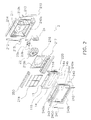
- FIG. 2 is an exploded perspective view of the internal structure of the indoor unit.
- the outer shell of the indoor unit 2 is formed by a frame 210 and a grill 240.
- a left plate 232, a right plate 213 and a top plate 214 are respectively fixed to the left end, the right end and the top end of a rectangular opening 211.
- the frame 210 includes a fan compartment 210a and an electric component compartment 21 0b.
- the grill 240 includes an upper blower vent 240a, a lower blower vent 240b, an opening 240c, a left suction vent 240d and a right suction vent 240e.
- the upper blower vent 240a is positioned on the upper part of the grill 240
- the lower blower vent 240b is positioned on the lower part of the grill 240.
- the opening 240c is formed for exposing a panel 14a to the indoor space.
- the left suction vent 240d is positioned on the left face of the grill 240
- the right suction vent 240e is positioned on the right face of the grill 240.
- Air is inhaled through the left suction vent 240d and the right suction vent 240e in conjunction with activation of the fan 23 and passes through a filter 218 disposed on the upstream of the convective heat exchanger 13 via spaces between the heat insulated rear face of the panel 14a and suction path forming plates 115 and 116. After passing through the filter 218, the air is directed to the convective heat exchanger 13. Heat exchange is then executed for the air in the convective heat exchanger 13. The heat-exchanged air passes through a circular hole 216a of a bell mouth 216 and enters the fan 23. The air is then blown out of the fan 23, travels through the fan compartment 210a towards the upper blower vent 240a and the lower blower vent 240b, and is blown out through the upper blower vent 240a and the lower blower vent 240b.
- the circular hole 216a of the bell mouth 216 has a diameter slightly less than the vane inner diameter of the fan 23.
- the air enters between the vanes of the fan 23 and is compressed by the vanes of the fan 23. The compressed air is blown out in the outer peripheral direction of the fan 23.
- a motor support plate 215 is disposed and fixed between the top and the bottom of the fan compartment 210a for supporting a driving motor 23a of the fan 23.
- the driving motor 23a is fixed to the motor support plate 215 by means of screws 23b.
- the bell mouth 216 then closes the fan compartment 210a.
- An electric component box 24 is held in the electric component compartment 210b.
- the electric component box 24 accommodates the control unit embedded with a CPU, a memory and etc.
- a heat exchanger assembly 220 is an integrated structure of the convective heat exchanger 13 and the radiant heat exchanger 14.
- a drain pan assembly 217 is disposed below the convective heat exchanger 13. During a cooling operation, for instance, moisture contained in the air is condensed on the surface of the convective heat exchanger 13 when the air passes through the conductive heat exchanger 13. The drain pan assembly 217 receives such condensed water falling from the convective heat exchanger 13.
- a blower vent assembly 250 is attached to the upper blower vent 240a.
- the blower vent assembly 250 includes a louver for changing an air blowing-out direction.
- a left frame bar 241, a right frame bar 242 and an upper frame bar 243 are respectively attached to the left edge, the right edge, and the upper edge of the opening 240c of the grill 240.
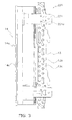
- FIG. 3 is a side view of the heat exchanger assembly.
- the convective heat exchanger 13 and the radiant heat exchanger 14 are fixed to each other by means of attachment plates 221.
- Each attachment plate 221 is a sheet-metal member extended from a frame 14c of the radiant heat exchanger 14 in an opposite direction to the panel 14a.
- Each attachment plate 221 includes through holes 221a.
- the convective heat exchanger 13 includes a pair of tube plates 13c in the vicinity of the both ends of each heat transfer tube 13b.
- Each tube plate 13c includes screw holes to be matched with the through holes 221a of the attachment plates 221.
- the convective heat exchanger 13 and the attachment plates 221 are fixed by means of screws via the through holes 221a.
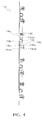
- FIG. 4 is a cross-sectional view of the radiant heat exchanger for illustrating an exemplary attachment structure of the panel and the heat transfer tubes.
- attachment brackets 14e are opposed to the panel 14a while heat transfer tubes 14b are interposed therebetween.
- the attachment brackets 14e are fixed to bracket receivers 14d having preliminarily fixed to the panel 14a by means of attachment screws 14f.
- Each bracket receiver 14d includes a screw hole 14da that one of the attachment screws 14f is screwed.
- Each attachment bracket 14e includes a flat plate portion 14ea, a bulged portion 14eb and flanged portions 14ec. The flat plate portion 14ea is closely attached to the rear face, opposite to the radiant face, of the panel 14a.
- the bulged portion 14eb is bulged from the flat plate portion 14ea for forming a U-shaped groove that one of the heat transfer tubes 14b is fitted.
- the flanged portions 14ec bulged from the both ends of the flat plate portion 14ea, are fixed to the bracket receivers 14d.
- Each flanged portion 14ec includes a through hole 14ed to be matched with the screw hole 14a of each bracket receiver 14d.
- the heat transfer tubes 14b are firstly disposed on the rear face of the panel 14a. Subsequently, the attachment brackets 14e are respectively disposed while the through holes l4ed thereof are faced to the screw holes 14a of the bracket receivers 14d. Under the condition, the flanged portions 14ec of the attachment brackets 14e are respectively fixed to the bracket receivers 14d by means of the attachment screws 14f. Consequently, the attachment brackets 14e and the heat transfer tubes 14b are pressed onto the panel 14a. Heat can be thereby reliably transferred from the attachment brackets 14e and the heat transfer tubes 14b to the panel 14a.
- the air conditioner 1 is configured to cause the four-way switching valve 12 to change the refrigerant flow path for switching between a cooling operation and a heating operation.
- the refrigerant circuit functions as a circuit for a heating operation.
- the flow path depicted with the solid line in FIG. 1 is selected in the four-way switching valve 12. Accordingly, the high pressure gas refrigerant, discharged from the compressor 11, branches into and flows through the branch pipe 40 and the convective heat exchanger 13.
- the branch point of the refrigerant flow is hereinafter referred to as a point A.
- the gas refrigerant, flowing into the branch pipe 40 at the point A sequentially flows through the open/close valve 41, the first check valve 42, the radiant heat exchanger 14 and the second check valve 43, and then joins the refrigerant flowing from the convective heat exchanger 13.
- the confluence of the refrigerant flows is hereinafter referred to as a point B.
- the attachment brackets 14e and the heat transfer tubes 14b are closely attached to the panel 14a (see FIG. 4 ).
- the heat of the gas refrigerant is thereby transferred to the panel 14a through the heat transfer tubes 14b. Accordingly, the panel 14a increases its temperature.
- the panel 14a with increased temperature herein emits radiant heat. Therefore, air and objects, positioned ahead the panel 14a, are heated by the radiant heat.
- the gas refrigerant is partially condensed by means of heat exchange with the panel 14a. Therefore, the liquid refrigerant and the gas refrigerant herein coexist in the radiant heat exchanger 14.
- the gas refrigerant, flowing into the convective heat exchanger 13 at the point A, is condensed as a result of heat exchange with the air flowing against the outside of the convective heat exchanger 13.
- the air increases its temperature in the convective heat exchanger 13 and is blown out to the indoor space for heating the indoor space.
- the liquid refrigerant, flowing out of the convective heat exchanger 13 joins the refrigerant flowing out of the radiant heat exchanger 14 at the point B.
- the joined refrigerant subsequently flows towards the outdoor heat exchanger 16.
- the joined refrigerant is decompressed in the expansion valve 15.
- the decompressed refrigerant then flows into the outdoor heat exchanger 16.
- the refrigerant evaporates and changes into the gas refrigerant as a result of heat exchange with the air flowing against the outside of the outdoor heat exchanger 16.
- the air conditioner 1 After flowing out of the outdoor heat exchanger 16, the gas refrigerant is returned to the compressor 11 via the four-way switching valve 12 and the accumulator 20.
- the air conditioner 1 is thus configured to execute a heating operation using the radiant heat exchanger 14 and the convective heat exchanger 13.
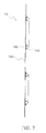
- FIG. 5 is a chart representing the relation between temperature to be detected by the second temperature sensor and actions of the open/close valve during a heating operation.
- the open/close valve 41 is configured to switch the flow path from an opened state to a closed state when the temperature detected by the second temperature sensor 114 exceeds a predetermined temperature (herein set as 70 degrees Celsius).
- a predetermined temperature herein set as 70 degrees Celsius.
- the open/close valve 41 is configured to switch a state of the refrigerant flowing into the radiant heat exchanger 14 to a state of the refrigerant flowing into only the convective heat exchanger 13 without flowing into the radiant heat exchanger 14.
- the open/close valve 41 is configured to switch the flow path back to the opened state from the closed state. Accordingly, the air conditioner 1 is returned to the heating operation using the radiant heat exchanger 14.
- the liquid refrigerant and the gas refrigerant remain residing between the open/close valve 41 and the point B.
- the liquid refrigerant spontaneously evaporates under the condition, the internal pressure is increased between the open/close valve 41 and the point B.
- the first check valve 42 is disposed between the radiant heat exchanger 14 and the open/close valve 41. Even when the liquid refrigerant spontaneously evaporates and the internal pressure is increased, the pressure within the radiant heat exchanger 14 does not affect the open/close valve 41. Further, less liquid refrigerant exists between the open/close valve 41 and the first check valve 42. Even when the liquid refrigerant existing therein spontaneously evaporates and the internal pressure is increased, the internal pressure is not increased enough to push and open the open/close valve 41. Therefore, occurrence of chattering is herein prevented.
- the refrigerant circuit functions as a circuit for a cooling operation.
- the flow path depicted with the dotted line in FIG. 1 is selected in the four-way switching valve 12.
- the high pressure gas refrigerant, discharged from the compressor 11 flows towards the outdoor heat exchanger 16.
- the gas refrigerant is condensed as a result of heat exchange with the air flowing against the outside of the outdoor heat exchanger 16.
- the liquid refrigerant, flowing out of the outdoor heat exchanger 16 flows towards the convective heat exchanger 13.
- the liquid refrigerant is decompressed in the expansion valve 15.
- the decompressed refrigerant then flows into the convective heat exchanger 13. It should be noted that the liquid and gas refrigerant is blocked from flowing into the branch pipe 40 at the point B by the second check valve 43 before flowing into the convective heat exchanger 13.
- the liquid refrigerant evaporates and changes into the gas refrigerant as a result of heat exchange with the air flowing against the outside of the convective heat exchanger 13.
- the air reduces its temperature in the convective heat exchanger 13 and is blown out to the indoor space for cooling the indoor space.
- the gas refrigerant flows out of the convective heat exchanger 13 and flows towards the four-way switching valve 12 via the point A.
- the gas refrigerant is then returned to the compressor 11 via the four-way switching valve 12 and the accumulator 20.
- the branch pipe 40 is configured to be closed by the open/close valve 41 for blocking the high pressure refrigerant from flowing into the radiant heat exchanger 14 when the temperature of the panel 14a of the radiant heat exchanger 14 reaches the upper limit of its permissive temperature during a heating operation using the radiant heat exchanger 14.
- the air conditioner 1 can be returned to the heating operation using the radiant heat exchanger 14.
- the first check valve 42 is disposed between the radiant heat exchanger 14 and the open/close valve 41. Therefore, less liquid refrigerant exists between the open/close valve 41 and the first check valve 42 when the open/close valve 41 is closed. Even when the liquid refrigerant spontaneously evaporates and the internal pressure is increased, the internal pressure is not increased enough to push and open the open/close valve 41. Therefore, occurrence of chattering is prevented.
- the open/close valve 41 is employed for closing and opening the branch pipe 40.
- an opening degree regulating valve may be used instead of the open/close valve 41.
- the opening degree regulating valve herein has a function of blocking the flow path of the branch pipe 40 and a function of regulating the opening degree of the flow path of the branch pipe 40.
- the opening degree regulating valve With the opening degree regulating valve, the temperature of the panel 14a of the radiant heat exchanger 14 is increased or reduced by regulating the opening degree of the flow path. Further, the flow path of the refrigerant is configured to be blocked when the temperature of the panel 14a reaches its upper limit. Therefore, the opening degree regulating valve can enhance convenience and safety of the air conditioner 1.
- the attachment structure of the panel 14a and the heat transfer tubes 14b in the radiant heat exchanger 14 is not limited to that illustrated in FIG. 4 .
- Other attachment structures will be hereinafter explained with reference to FIGS. 6 to 10 .
- the face, opposite to the radiant face, of the panel 14a will be hereinafter referred to as a rear face for the sake of easy explanation.
- FIG. 6 is a cross-sectional view of the radiant heat exchanger for illustrating a second attachment structure of the panel and the heat transfer tubes.
- each of attachment panels 141 includes a flat plate portion 141a and bulged portions 141b.
- the flat plate portion 141a is joined to the rear face of the panel 14a, whereas the bulged portions 14b are bulged from the that plate portion 141a.
- Each bulged portion 141b is bulged higher than the diameter of each heat transfer tube 14b.
- Each bulged portion 141b includes a U-shaped groove 141c that one of the heat transfer tubes 14b is fitted.
- Each heat transfer tube 14b is fitted into corresponding one of the U-shaped grooves 141c and then the edges of the opening of the U-shaped groove 141c are pressed and swaged onto the outer peripheral surface of each heat transfer tube 14b.
- FIG. 7 is a cross-sectional view of the radiant heat exchanger for illustrating a third attachment structure of the panel and the heat transfer tubes.
- the panel 14a and the heat transfer tubes 14b are jointed by means of brazing.
- a filler material 140 is filled with corners (i.e., clearances) produced in contact portions between the panel 14a and the heat transfer tubes 14b. Therefore, heat can be efficiently transferred from the heat transfer tubes 14b to the panel 14a.
- FIG. 8 is a cross-sectional view of the radiant heat exchanger for illustrating a fourth attachment structure of the panel and the heat transfer tubes.
- each of first attachment brackets 341 includes a flat plate portion 344a and a bulged portion 341b.
- the flat plate portion 341a is joined to the rear face of the panel 14a, whereas the bulged portion 341b is bulged from the flat plate portion 341a.
- the flat plate portion 341a is closely joined to the rear face of the panel 14a by means of either spot welding or brazing.
- the bulged portion 341b is bulged at a height roughly the same as the diameter of each heat transfer tube 14b.
- the bulged portion 341b includes a U-shaped groove 341c that one of the heat transfer tubes 14b is fitted. Further, the bulged portion 341b includes screw holes 341 d on the both sides of the U-shaped groove 341c.
- Each of second attachment brackets 342 includes through holes 342a to be matched with the screw holes 341d of corresponding one of the first attachment brackets 341.
- the second attachment brackets 342 are respectively fixed to the first attachment brackets 341 by means of screws 343 for covering the heat transfer tubes 14b respectively fitted into the U-shaped grooves 341c.
- the respective heat transfer tubes 14b are herein slightly protruded from the U-shaped grooves 341c. Therefore, the heat transfer tubes 14b are respectively pressed and closely fitted to the U-shaped grooves 341c when the second attachment brackets 342 are respectively fixed to the first attachment brackets 341 by means of screws.
- FIG. 9 is a cross-sectional view of the radiant heat exchanger for illustrating a fifth attachment structure of the panel and the heat transfer tubes.
- each of presser brackets 441 includes a flat plate portion 441a and a U-shaped groove 441b.
- the flat plate portion 441a is joined to the rear face of the panel 14a.
- the U-shaped groove 441b is opposed to the rear face of the panel 14a while one of the heat transfer tubes 14b is interposed therebteween.
- the heat transfer tubes 14b are disposed on the rear face of the panel 14a and are then respectively covered with the U-shaped grooves 441b of the presser brackets 441. Under the condition, the flat plate portions 441a of the presser brackets 441 and the rear face of the panel 14a are joined by means of either spot welding or brazing.
- FIG. 10 is a cross-sectional view of the radiant heat exchanger for illustrating a sixth attachment structure of the panel and the heat transfer tubes.
- the panel 14a includes bulged portions 541 on the rear face thereof.
- the bulged portions 541 are arranged in the positions where the heat transfer tubes 14b are disposed.
- Each bulged portion 541 includes a U-shaped groove 541a that one of the heat transfer tubes 14b is fitted.
- the U-shaped groove 541a has a predetermined depth for allowing the outer peripheral surface of each heat transfer tube 14b to be slightly protruded therefrom when fitted therein.
- each bulged portion 541 includes screw holes 541b on the both sides of the U-shaped groove 541a.
- Each of presser brackets 542 includes through holes 542a to be matched with the screw holes 541b of corresponding one of the bulged portions 541.
- the presser brackets 542 are respectively fixed to the bulged portions 541 by means of screws 543 for covering the outer peripheral surfaces of the heat transfer tubes 14b respectively slightly protruded from the bulged portions 541.
- the present invention is useful for a heating machine using a radiant heat exchanger.
Landscapes
- Engineering & Computer Science (AREA)
- Mechanical Engineering (AREA)
- General Engineering & Computer Science (AREA)
- Physics & Mathematics (AREA)
- Thermal Sciences (AREA)
- Combustion & Propulsion (AREA)
- Chemical & Material Sciences (AREA)
- Life Sciences & Earth Sciences (AREA)
- Sustainable Development (AREA)
- Devices For Blowing Cold Air, Devices For Blowing Warm Air, And Means For Preventing Water Condensation In Air Conditioning Units (AREA)
- Air Filters, Heat-Exchange Apparatuses, And Housings Of Air-Conditioning Units (AREA)
- Air Conditioning Control Device (AREA)
- Other Air-Conditioning Systems (AREA)
Abstract
It is an object of the present invention to provide an air conditioner preventing occurrence of chattering even when a refrigerant, changed into liquid in a radiant heat exchanger, resides in the vicinity of the radiant heat exchanger and an open/close valve during a heating operation. In an air conditioner (1), a first check valve (42) is disposed between a radiant heat exchanger (14) and an open/close valve (41). When the open/close valve (41) is closed, less liquid refrigerant exists between the open/close valve (41) and the first check valve (42). Even when the liquid refrigerant spontaneously evaporates and the internal pressure is increased, the internal pressure is not increased enough to push and open the open/close valve (41). Occurrence of chattering is thereby prevented.
Description
- The present invention relates to an air conditioner including a refrigerant circuit configured to execute a vapor compression refrigeration cycle.
- Patent Literature 1 (Japan Laid-open Patent Application Publication No.
JP-A-H07-055234 JP-A-H07-055234 - In the aforementioned structure, however, the high pressure refrigerant is trapped in the radiant heat exchanger by means of the pressure of a compressor. Accordingly, the refrigerant, a compressor oil and etc. reside in the radiant heat exchanger. This makes it difficult to lower the temperature of the refrigerant. In other words, the temperature of the radiant heat exchanger cannot be lowered when necessary. Further, the amount of the compressor oil to be returned to the compressor is reduced. Therefore, chances will be increased that reliability of the compressor is deteriorated.
- In view of the above, the applicant of the present invention produced a structure for preventing the high pressure refrigerant from being trapped in the radiant heat exchanger. Specifically in the structure, an open/close valve is disposed on the upstream of the radiant heat exchanger for blocking the flow path of the high pressure refrigerant flowing towards the radiant heat exchanger. Even in the structure, the refrigerant is changed into liquid in the radiant heat exchanger during a heating operation and resides in the vicinity of the radiant heat exchanger and the open/close valve. When the liquid refrigerant spontaneously evaporates under the condition and the internal pressure is increased, the open/close valve is pushed and repeatedly opened and closed by means of the increased internal pressure. This phenomenon is so-called "chattering".
- It is an object of the present invention to provide an air conditioner preventing occurrence of chattering in an open/close valve even when a refrigerant is changed into liquid in a radiant heat exchanger and resides in the vicinity of the radiant heat exchanger and the open/close valve during a heating operation.
- An air conditioner according to a first aspect of the present invention includes a refrigerant circuit configured to execute a vapor compression refrigeration cycle and is configured to execute a heating operation using at least a high pressure refrigerant. In the air conditioner, the refrigerant circuit includes a convective heat exchanger, a radiant heat exchanger, an open/close valve and a check valve. The convective heat exchanger is configured to execute heat exchange between the high pressure refrigerant flowing through the inside thereof and an air flowing towards the outside thereof. The radiant heat exchanger is configured to heat a predetermined member by means of the high pressure refrigerant flowing through the inside thereof for causing the predetermined member to emit a radiant heat. The open/close valve is disposed on the upstream of the radiant heat exchanger for blocking a flow path of the high pressure refrigerant flowing towards the radiant heat exchanger during the heating operation. The check valve is disposed between the radiant heat exchanger and the open/close valve.
- According to the air conditioner of the first aspect of the present invention, the check valve is disposed between the radiant heat exchanger and the open/close valve. When the open/close valve is closed, less liquid refrigerant exists between the open/close valve and the check valve. Even when the liquid refrigerant spontaneously evaporates and the internal pressure is increased, the internal pressure is not increased enough to push and open the open/close valve. Occurrence of chattering is thereby prevented.
- An air conditioner according to a second aspect of the present invention relates to the air conditioner according to the first aspect of the present invention. In the air conditioner, the open/close valve is an opening degree regulating valve having a function of blocking the flow path and a function of regulating an opening degree of the flow path.
- According to the air conditioner of the second aspect of the present invention, performance of the radiant heat exchanger is increased or reduced by regulating the opening degree of the refrigerant flow path. Further, the refrigerant flow path is configured to be blocked when the performance of the radiant heat exchanger reaches a predetermined set value. Convenience and security of the air conditioner can be thereby enhanced.
- An air conditioner according to a third aspect of the present invention relates to the air conditioner according to one of the first and second aspects of the present invention. In the air conditioner, the open/close valve is configured to block the flow path when a temperature of the predetermined member reaches an upper limit of a permissive temperature.
- According to the air conditioner of the third aspect of the present invention, the high pressure refrigerant is prevented from flowing into the radiant heat exchanger when the temperature of the predetermined member of the radiant heat exchanger reaches the upper limit of the permissive temperature thereof during execution of a heating operation using the radiant heat exchanger. Therefore, reduction in the temperature of the refrigerant is accelerated within the radiant heat exchanger. As a result, reduction in the temperature of the predetermined member is accelerated and the air conditioner can be returned to the heating operation using the radiant heat exchanger.
- According to the air conditioner of the first aspect of the present invention, less liquid refrigerant exists between the open/close valve and the check valve. Even when the liquid refrigerant spontaneously evaporates and the internal pressure is increased, the internal pressure is not increased enough to push and open the open/close valve. Occurrence of chattering is thereby prevented.
- According to the air conditioner of the second aspect of the present invention, performance of the radiant heat exchanger is increased or reduced by regulating the opening degree of the refrigerant flow path. Further, the refrigerant flow path is configured to be blocked when the performance of the radiant heat exchanger reaches a predetermined set value. Convenience and security of the air conditioner can be thereby enhanced.
- According to the air conditioner of the third aspect of the present invention, the high pressure refrigerant is prevented from flowing into the radiant heat exchanger when the temperature of the predetermined member of the radiant heat exchanger reaches the upper limit of the permissive temperature thereof during execution of a heating operation using the radiant heat exchanger. Therefore, reduction in the temperature of the refrigerant is accelerated within the radiant heat exchanger. As a result, reduction in the temperature of the predetermined member is accelerated and the air conditioner can be returned to the heating operation using the radiant heat exchanger.
-
-
FIG. 1 is a refrigerant circuit diagram of an air conditioner according to an exemplary embodiment of the present invention. -
FIG. 2 is an exploded perspective view of the internal structure of an indoor unit. -
FIG. 3 is a side view of a heat exchanger assembly. -
FIG. 4 is a cross-sectional view of a radiant heat exchanger, illustrating an exemplary attachment structure of a panel and heat transfer tubes. -
FIG. 5 is a chart representing the relation between temperature to be detected by a second temperature sensor and actions of an open/close valve during a heating operation. -
FIG. 6 is a cross-sectional view of the radiant heat exchanger, illustrating a second attachment structure of the panel and the heat transfer tubes. -
FIG. 7 is a cross-sectional view of the radiant heat exchanger, illustrating a third attachment structure of the panel and the heat transfer tubes. - FIG. is a cross-sectional view of the radiant heat exchanger, illustrating a fourth attachment structure of the panel and the heat transfer tubes.
-
FIG. 9 is a cross-sectional view of the radiant heat exchanger, illustrating a fifth attachment structure of the panel and the heat transfer tubes. -
FIG. 10 is a cross-sectional view of the radiant heat exchanger, illustrating a sixth attachment structure of the panel and the heat transfer tubes. - An exemplary embodiment of the present invention will be hereinafter explained with reference to figures. It should be noted that the following exemplary embodiment is merely a specific example of the present invention, and therefore does not intend to limit the technical scope of the present invention.
-
FIG. 1 is a refrigerant circuit diagram of an air conditioner according to the exemplary embodiment of the present invention. As illustrated inFIG. 1 , the air conditioner 1 includes an indoor unit 2 mainly disposed in the indoor space and anoutdoor unit 3 mainly disposed in the outdoor space. The indoor unit 2 and theoutdoor unit 3 are connected through a refrigerant communication piping, and the structure forms arefrigerant circuit 10 configured to execute a vapor compression refrigeration cycle. - In the
refrigerant circuit 10, acompressor 11, a four-way switching valve 12, aconvective heat exchanger 13, anexpansion valve 15, anoutdoor heat exchanger 16 are sequentially connected. Further, abranch pipe 40 is disposed in parallel to theconvective heat exchanger 13. An open/close valve 41, afirst check valve 42, aradiant heat exchanger 14 and asecond check valve 43 are series-connected to thebranch pipe 40 while being sequentially aligned from thecompressor 11 side. Further, anaccumulator 20 is connected to the four-way switching valve 12 and the inlet of thecompressor 11. - The four-
way switching valve 12 is configured to cause the refrigerant discharged from thecompressor 11 to flow towards either theconvective heat exchanger 13 or theoutdoor heat exchanger 16. During a heating operation, for instance, a control unit is configured to cause the four-way switching valve 12 to select a flow path depicted with a solid line inFIG. 1 for causing the refrigerant to flow towards theconvective heat exchanger 13. During a cooling operation, by contrast, the control unit is configured to cause the four-way switching valve 12 to select a flow path depicted with a dotted line inFIG. 1 for causing the refrigerant to flow towards theoutdoor heat exchanger 16. - The
convective heat exchanger 13 is a type of heat exchanger formed by a plurality of fins and a plurality of heat transfer tubes arranged perpendicularly to the fins. Theconvective heat exchanger 13 is configured to execute heat exchange between the refrigerant flowing through the heat transfer tubes and the air flowing against the surfaces of the fins. Afan 23 is disposed in the vicinity of theconvective heat exchanger 13 for supplying air towards the surfaces of the fins. - The
radiant heat exchanger 14 is a type of heat exchanger formed by a plate (hereinafter referred to as a panel) made of aluminum and heat transfer tubes attached to the panel. Theradiant heat exchanger 14 is configured to heat the panel by means of the high pressure refrigerant flowing through the heat transfer tubes for causing the panel to emit radiant heat. - The
expansion valve 15 is an electronic expansion valve functioning as a decompression mechanism. Theexpansion valve 15 is connected between theconvective heat exchanger 13 and theoutdoor heat exchanger 16. Theexpansion valve 15 is configured to narrow the refrigerant flow path for decompressing the refrigerant. Theoutdoor heat exchanger 16 is a type of heat exchanger formed by a plurality of fins and a plurality of heat transfer tubes arranged perpendicularly to the fins. Theoutdoor heat exchanger 16 is configured to execute heat exchange between the refrigerant flowing through the heat transfer tubes and the air flowing against the surfaces of the fins. Further, anoutdoor fan 33 is disposed in the vicinity of theoutdoor heat exchanger 16 for supplying air towards the surfaces of the fins. Theaccumulator 20 is configured to accumulate excessive liquid refrigerant and return only gas refrigerant to thecompressor 11. - A
discharge temperature sensor 111 is attached to a discharge pipe connecting the outlet of thecompressor 11 and the four-way switching valve 12. Thedischarge temperature sensor 111 is configured to detect the temperature of the high pressure refrigerant to be discharged from thecompressor 11. - The control unit is configured to control the temperature of the panel of the
radiant heat exchanger 14 based on the temperature to be detected by thedischarge temperature sensor 111. However, another temperature sensor (hereinafter referred to as a second temperature sensor 114) may be attached in the vicinity of the high pressure refrigerant inlet of theradiant heat exchanger 14 when the temperature to be detected by thedischarge temperature sensor 111 and the temperature of the panel are different due to pressure loss caused by a long pipe connecting the open/close valve 41 and theradiant heat exchanger 14. It should be noted that both of thedischarge temperature sensor 111 and the second temperature sensor 114 are used in the present exemplary embodiment. -
FIG. 2 is an exploded perspective view of the internal structure of the indoor unit. InFIG. 2 , the outer shell of the indoor unit 2 is formed by aframe 210 and agrill 240. In theframe 210, a left plate 232, aright plate 213 and atop plate 214 are respectively fixed to the left end, the right end and the top end of arectangular opening 211. Theframe 210 includes afan compartment 210a and an electric component compartment 21 0b. - The
grill 240 includes anupper blower vent 240a, alower blower vent 240b, anopening 240c, aleft suction vent 240d and aright suction vent 240e. Theupper blower vent 240a is positioned on the upper part of thegrill 240, whereas thelower blower vent 240b is positioned on the lower part of thegrill 240. Theopening 240c is formed for exposing apanel 14a to the indoor space. Theleft suction vent 240d is positioned on the left face of thegrill 240, whereas theright suction vent 240e is positioned on the right face of thegrill 240. - Air is inhaled through the
left suction vent 240d and theright suction vent 240e in conjunction with activation of thefan 23 and passes through afilter 218 disposed on the upstream of theconvective heat exchanger 13 via spaces between the heat insulated rear face of thepanel 14a and suctionpath forming plates filter 218, the air is directed to theconvective heat exchanger 13. Heat exchange is then executed for the air in theconvective heat exchanger 13. The heat-exchanged air passes through acircular hole 216a of abell mouth 216 and enters thefan 23. The air is then blown out of thefan 23, travels through thefan compartment 210a towards theupper blower vent 240a and thelower blower vent 240b, and is blown out through theupper blower vent 240a and thelower blower vent 240b. - The
circular hole 216a of thebell mouth 216 has a diameter slightly less than the vane inner diameter of thefan 23. When passing through thecircular hole 216a, the air enters between the vanes of thefan 23 and is compressed by the vanes of thefan 23. The compressed air is blown out in the outer peripheral direction of thefan 23. - A
motor support plate 215 is disposed and fixed between the top and the bottom of thefan compartment 210a for supporting a drivingmotor 23a of thefan 23. The drivingmotor 23a is fixed to themotor support plate 215 by means ofscrews 23b. Thebell mouth 216 then closes thefan compartment 210a. Anelectric component box 24 is held in theelectric component compartment 210b. Theelectric component box 24 accommodates the control unit embedded with a CPU, a memory and etc. - A
heat exchanger assembly 220 is an integrated structure of theconvective heat exchanger 13 and theradiant heat exchanger 14. Adrain pan assembly 217 is disposed below theconvective heat exchanger 13. During a cooling operation, for instance, moisture contained in the air is condensed on the surface of theconvective heat exchanger 13 when the air passes through theconductive heat exchanger 13. Thedrain pan assembly 217 receives such condensed water falling from theconvective heat exchanger 13. - It should be noted that a
blower vent assembly 250 is attached to theupper blower vent 240a. Theblower vent assembly 250 includes a louver for changing an air blowing-out direction. Further, a left frame bar 241, aright frame bar 242 and anupper frame bar 243 are respectively attached to the left edge, the right edge, and the upper edge of theopening 240c of thegrill 240. -
FIG. 3 is a side view of the heat exchanger assembly. In theheat exchanger assembly 220 ofFIG. 3 , theconvective heat exchanger 13 and theradiant heat exchanger 14 are fixed to each other by means ofattachment plates 221. Eachattachment plate 221 is a sheet-metal member extended from aframe 14c of theradiant heat exchanger 14 in an opposite direction to thepanel 14a. Eachattachment plate 221 includes throughholes 221a. - The
convective heat exchanger 13 includes a pair oftube plates 13c in the vicinity of the both ends of eachheat transfer tube 13b. Eachtube plate 13c includes screw holes to be matched with the throughholes 221a of theattachment plates 221. Theconvective heat exchanger 13 and theattachment plates 221 are fixed by means of screws via the throughholes 221a. -
FIG. 4 is a cross-sectional view of the radiant heat exchanger for illustrating an exemplary attachment structure of the panel and the heat transfer tubes. InFIG. 4 ,attachment brackets 14e are opposed to thepanel 14a whileheat transfer tubes 14b are interposed therebetween. Specifically, theattachment brackets 14e are fixed tobracket receivers 14d having preliminarily fixed to thepanel 14a by means ofattachment screws 14f. Eachbracket receiver 14d includes a screw hole 14da that one of the attachment screws 14f is screwed. Eachattachment bracket 14e includes a flat plate portion 14ea, a bulged portion 14eb and flanged portions 14ec. The flat plate portion 14ea is closely attached to the rear face, opposite to the radiant face, of thepanel 14a. The bulged portion 14eb is bulged from the flat plate portion 14ea for forming a U-shaped groove that one of theheat transfer tubes 14b is fitted. The flanged portions 14ec, bulged from the both ends of the flat plate portion 14ea, are fixed to thebracket receivers 14d. Each flanged portion 14ec includes a through hole 14ed to be matched with thescrew hole 14a of eachbracket receiver 14d. - The
heat transfer tubes 14b are firstly disposed on the rear face of thepanel 14a. Subsequently, theattachment brackets 14e are respectively disposed while the through holes l4ed thereof are faced to the screw holes 14a of thebracket receivers 14d. Under the condition, the flanged portions 14ec of theattachment brackets 14e are respectively fixed to thebracket receivers 14d by means of the attachment screws 14f. Consequently, theattachment brackets 14e and theheat transfer tubes 14b are pressed onto thepanel 14a. Heat can be thereby reliably transferred from theattachment brackets 14e and theheat transfer tubes 14b to thepanel 14a. - The air conditioner 1 is configured to cause the four-
way switching valve 12 to change the refrigerant flow path for switching between a cooling operation and a heating operation. First, an exemplary case will be explained that the refrigerant circuit functions as a circuit for a heating operation. - During a heating operation, the flow path depicted with the solid line in
FIG. 1 is selected in the four-way switching valve 12. Accordingly, the high pressure gas refrigerant, discharged from thecompressor 11, branches into and flows through thebranch pipe 40 and theconvective heat exchanger 13. The branch point of the refrigerant flow is hereinafter referred to as a point A. The gas refrigerant, flowing into thebranch pipe 40 at the point A, sequentially flows through the open/close valve 41, thefirst check valve 42, theradiant heat exchanger 14 and thesecond check valve 43, and then joins the refrigerant flowing from theconvective heat exchanger 13. The confluence of the refrigerant flows is hereinafter referred to as a point B. - The
attachment brackets 14e and theheat transfer tubes 14b are closely attached to thepanel 14a (seeFIG. 4 ). The heat of the gas refrigerant is thereby transferred to thepanel 14a through theheat transfer tubes 14b. Accordingly, thepanel 14a increases its temperature. Thepanel 14a with increased temperature herein emits radiant heat. Therefore, air and objects, positioned ahead thepanel 14a, are heated by the radiant heat. In theradiant heat exchanger 14, the gas refrigerant is partially condensed by means of heat exchange with thepanel 14a. Therefore, the liquid refrigerant and the gas refrigerant herein coexist in theradiant heat exchanger 14. - The gas refrigerant, flowing into the
convective heat exchanger 13 at the point A, is condensed as a result of heat exchange with the air flowing against the outside of theconvective heat exchanger 13. On the other hand, the air increases its temperature in theconvective heat exchanger 13 and is blown out to the indoor space for heating the indoor space. - Further, the liquid refrigerant, flowing out of the
convective heat exchanger 13, joins the refrigerant flowing out of theradiant heat exchanger 14 at the point B. The joined refrigerant subsequently flows towards theoutdoor heat exchanger 16. On the way to theoutdoor heat exchanger 16, the joined refrigerant is decompressed in theexpansion valve 15. The decompressed refrigerant then flows into theoutdoor heat exchanger 16. In theoutdoor heat exchanger 16, the refrigerant evaporates and changes into the gas refrigerant as a result of heat exchange with the air flowing against the outside of theoutdoor heat exchanger 16. - After flowing out of the
outdoor heat exchanger 16, the gas refrigerant is returned to thecompressor 11 via the four-way switching valve 12 and theaccumulator 20. The air conditioner 1 is thus configured to execute a heating operation using theradiant heat exchanger 14 and theconvective heat exchanger 13. -
FIG. 5 is a chart representing the relation between temperature to be detected by the second temperature sensor and actions of the open/close valve during a heating operation. InFIG. 5 , the open/close valve 41 is configured to switch the flow path from an opened state to a closed state when the temperature detected by the second temperature sensor 114 exceeds a predetermined temperature (herein set as 70 degrees Celsius). In other words, the open/close valve 41 is configured to switch a state of the refrigerant flowing into theradiant heat exchanger 14 to a state of the refrigerant flowing into only theconvective heat exchanger 13 without flowing into theradiant heat exchanger 14. - When a preliminarily set switching period of time T1 elapses, the open/
close valve 41 is configured to switch the flow path back to the opened state from the closed state. Accordingly, the air conditioner 1 is returned to the heating operation using theradiant heat exchanger 14. - During a heating operation only using the
convective heat exchanger 13, the liquid refrigerant and the gas refrigerant remain residing between the open/close valve 41 and the point B. When the liquid refrigerant spontaneously evaporates under the condition, the internal pressure is increased between the open/close valve 41 and the point B. In the present exemplary embodiment, however, thefirst check valve 42 is disposed between theradiant heat exchanger 14 and the open/close valve 41. Even when the liquid refrigerant spontaneously evaporates and the internal pressure is increased, the pressure within theradiant heat exchanger 14 does not affect the open/close valve 41. Further, less liquid refrigerant exists between the open/close valve 41 and thefirst check valve 42. Even when the liquid refrigerant existing therein spontaneously evaporates and the internal pressure is increased, the internal pressure is not increased enough to push and open the open/close valve 41. Therefore, occurrence of chattering is herein prevented. - When the
panel 14a of theradiant heat exchanger 14 sufficiently reduces its temperature during a heating operation only using theconvective heat exchanger 13, thebranch pipe 40 is opened by the open/close valve 41 and the heating operation is again executed by theradiant heat exchanger 14 and theconvective heat exchanger 13. - Next, an exemplary case will be explained that the refrigerant circuit functions as a circuit for a cooling operation. During a cooling operation, the flow path depicted with the dotted line in
FIG. 1 is selected in the four-way switching valve 12. Accordingly, the high pressure gas refrigerant, discharged from thecompressor 11, flows towards theoutdoor heat exchanger 16. The gas refrigerant is condensed as a result of heat exchange with the air flowing against the outside of theoutdoor heat exchanger 16. The liquid refrigerant, flowing out of theoutdoor heat exchanger 16, flows towards theconvective heat exchanger 13. On the way to theconvective heat exchanger 13, the liquid refrigerant is decompressed in theexpansion valve 15. The decompressed refrigerant then flows into theconvective heat exchanger 13. It should be noted that the liquid and gas refrigerant is blocked from flowing into thebranch pipe 40 at the point B by thesecond check valve 43 before flowing into theconvective heat exchanger 13. - In the
convective heat exchanger 13, the liquid refrigerant evaporates and changes into the gas refrigerant as a result of heat exchange with the air flowing against the outside of theconvective heat exchanger 13. On the other hand, the air reduces its temperature in theconvective heat exchanger 13 and is blown out to the indoor space for cooling the indoor space. The gas refrigerant flows out of theconvective heat exchanger 13 and flows towards the four-way switching valve 12 via the point A. The gas refrigerant is then returned to thecompressor 11 via the four-way switching valve 12 and theaccumulator 20. - According to the air conditioner 1, as described above, the
branch pipe 40 is configured to be closed by the open/close valve 41 for blocking the high pressure refrigerant from flowing into theradiant heat exchanger 14 when the temperature of thepanel 14a of theradiant heat exchanger 14 reaches the upper limit of its permissive temperature during a heating operation using theradiant heat exchanger 14. As a result, reduction in the temperature of the refrigerant is accelerated within theradiant heat exchanger 14 and reduction in the temperature of thepanel 14a is also accelerated. Therefore, the air conditioner 1 can be returned to the heating operation using theradiant heat exchanger 14. - Further, the
first check valve 42 is disposed between theradiant heat exchanger 14 and the open/close valve 41. Therefore, less liquid refrigerant exists between the open/close valve 41 and thefirst check valve 42 when the open/close valve 41 is closed. Even when the liquid refrigerant spontaneously evaporates and the internal pressure is increased, the internal pressure is not increased enough to push and open the open/close valve 41. Therefore, occurrence of chattering is prevented. - In the aforementioned exemplary embodiment, the open/
close valve 41 is employed for closing and opening thebranch pipe 40. However, an opening degree regulating valve may be used instead of the open/close valve 41. The opening degree regulating valve herein has a function of blocking the flow path of thebranch pipe 40 and a function of regulating the opening degree of the flow path of thebranch pipe 40. - With the opening degree regulating valve, the temperature of the
panel 14a of theradiant heat exchanger 14 is increased or reduced by regulating the opening degree of the flow path. Further, the flow path of the refrigerant is configured to be blocked when the temperature of thepanel 14a reaches its upper limit. Therefore, the opening degree regulating valve can enhance convenience and safety of the air conditioner 1. - The attachment structure of the
panel 14a and theheat transfer tubes 14b in theradiant heat exchanger 14 is not limited to that illustrated inFIG. 4 . Other attachment structures will be hereinafter explained with reference toFIGS. 6 to 10 . It should be noted that the face, opposite to the radiant face, of thepanel 14a will be hereinafter referred to as a rear face for the sake of easy explanation. -
FIG. 6 is a cross-sectional view of the radiant heat exchanger for illustrating a second attachment structure of the panel and the heat transfer tubes. InFIG. 6 , each ofattachment panels 141 includes aflat plate portion 141a and bulgedportions 141b. Theflat plate portion 141a is joined to the rear face of thepanel 14a, whereas the bulgedportions 14b are bulged from the thatplate portion 141a. Each bulgedportion 141b is bulged higher than the diameter of eachheat transfer tube 14b. Each bulgedportion 141b includes aU-shaped groove 141c that one of theheat transfer tubes 14b is fitted. Eachheat transfer tube 14b is fitted into corresponding one of theU-shaped grooves 141c and then the edges of the opening of theU-shaped groove 141c are pressed and swaged onto the outer peripheral surface of eachheat transfer tube 14b. -
FIG. 7 is a cross-sectional view of the radiant heat exchanger for illustrating a third attachment structure of the panel and the heat transfer tubes. InFIG. 7 , thepanel 14a and theheat transfer tubes 14b are jointed by means of brazing. In this case, afiller material 140 is filled with corners (i.e., clearances) produced in contact portions between thepanel 14a and theheat transfer tubes 14b. Therefore, heat can be efficiently transferred from theheat transfer tubes 14b to thepanel 14a. -
FIG. 8 is a cross-sectional view of the radiant heat exchanger for illustrating a fourth attachment structure of the panel and the heat transfer tubes. InFIG. 8 , each offirst attachment brackets 341 includes a flat plate portion 344a and a bulgedportion 341b. Theflat plate portion 341a is joined to the rear face of thepanel 14a, whereas the bulgedportion 341b is bulged from theflat plate portion 341a. Theflat plate portion 341a is closely joined to the rear face of thepanel 14a by means of either spot welding or brazing. The bulgedportion 341b is bulged at a height roughly the same as the diameter of eachheat transfer tube 14b. The bulgedportion 341b includes aU-shaped groove 341c that one of theheat transfer tubes 14b is fitted. Further, the bulgedportion 341b includes screw holes 341 d on the both sides of theU-shaped groove 341c. - Each of
second attachment brackets 342 includes throughholes 342a to be matched with the screw holes 341d of corresponding one of thefirst attachment brackets 341. Thesecond attachment brackets 342 are respectively fixed to thefirst attachment brackets 341 by means ofscrews 343 for covering theheat transfer tubes 14b respectively fitted into theU-shaped grooves 341c. The respectiveheat transfer tubes 14b are herein slightly protruded from theU-shaped grooves 341c. Therefore, theheat transfer tubes 14b are respectively pressed and closely fitted to theU-shaped grooves 341c when thesecond attachment brackets 342 are respectively fixed to thefirst attachment brackets 341 by means of screws. -
FIG. 9 is a cross-sectional view of the radiant heat exchanger for illustrating a fifth attachment structure of the panel and the heat transfer tubes. InFIG. 9 , each ofpresser brackets 441 includes aflat plate portion 441a and aU-shaped groove 441b. Theflat plate portion 441a is joined to the rear face of thepanel 14a. TheU-shaped groove 441b is opposed to the rear face of thepanel 14a while one of theheat transfer tubes 14b is interposed therebteween. Specifically, theheat transfer tubes 14b are disposed on the rear face of thepanel 14a and are then respectively covered with theU-shaped grooves 441b of thepresser brackets 441. Under the condition, theflat plate portions 441a of thepresser brackets 441 and the rear face of thepanel 14a are joined by means of either spot welding or brazing. -
FIG. 10 is a cross-sectional view of the radiant heat exchanger for illustrating a sixth attachment structure of the panel and the heat transfer tubes. InFIG. 10 , thepanel 14a includes bulgedportions 541 on the rear face thereof. The bulgedportions 541 are arranged in the positions where theheat transfer tubes 14b are disposed. Each bulgedportion 541 includes aU-shaped groove 541a that one of theheat transfer tubes 14b is fitted. TheU-shaped groove 541a has a predetermined depth for allowing the outer peripheral surface of eachheat transfer tube 14b to be slightly protruded therefrom when fitted therein. Further, each bulgedportion 541 includes screw holes 541b on the both sides of theU-shaped groove 541a. - Each of
presser brackets 542 includes throughholes 542a to be matched with the screw holes 541b of corresponding one of the bulgedportions 541. Thepresser brackets 542 are respectively fixed to the bulgedportions 541 by means ofscrews 543 for covering the outer peripheral surfaces of theheat transfer tubes 14b respectively slightly protruded from the bulgedportions 541. - As described above, the present invention is useful for a heating machine using a radiant heat exchanger.
-
- 1
- Air conditioner
- 10
- Refrigerant circuit
- 13
- Convective heat exchanger
- 14
- Radiant heat exchanger
- 41
- Open/close valve
- 42
- First check valve
- PTL 1: Japan Laid-open Patent Application Publication No.
JP-A-H07-055234
Claims (3)
- An air conditioner (1) including a refrigerant circuit (10) configured to execute a vapor compression refrigeration cycle, the air conditioner (1) configured to execute a heating operation using at least a high pressure refrigerant,
wherein the refrigerant circuit (10) includes:a convective heat exchanger (13) configured to execute heat exchange between the high pressure refrigerant flowing through the inside thereof and an air flowing towards the outside thereof;a radiant heat exchanger (14) configured to heat a predetermined member by means of the high pressure refrigerant flowing through the inside thereof for causing the predetermined member to emit a radiant heat;an open/close valve (41) disposed on the upstream of the radiant heat exchanger (14) for blocking a flow path of the high pressure refrigerant flowing towards the radiant heat exchanger (14) during the heating operation; anda check valve (42) disposed between the radiant heat exchanger (14) and the open/close valve (41). - The air conditioner (1) recited in claim 1, wherein the open/close valve (41) is an opening degree regulating valve having a function of blocking the flow path and a function of regulating an opening degree of the flow path.
- The air conditioner (1) recited in one of claims 1 and 2, wherein the open/close valve (41) is configured to block the flow path when a temperature of the predetermined member reaches an upper limit of a permissive temperature.
Applications Claiming Priority (2)
| Application Number | Priority Date | Filing Date | Title |
|---|---|---|---|
| JP2009066768A JP5229031B2 (en) | 2009-03-18 | 2009-03-18 | air conditioner |
| PCT/JP2010/001812 WO2010106771A1 (en) | 2009-03-18 | 2010-03-15 | Air conditioner |
Publications (1)
| Publication Number | Publication Date |
|---|---|
| EP2410250A1 true EP2410250A1 (en) | 2012-01-25 |
Family
ID=42739438
Family Applications (1)
| Application Number | Title | Priority Date | Filing Date |
|---|---|---|---|
| EP10753268A Withdrawn EP2410250A1 (en) | 2009-03-18 | 2010-03-15 | Air conditioner |
Country Status (6)
| Country | Link |
|---|---|
| US (1) | US20120000224A1 (en) |
| EP (1) | EP2410250A1 (en) |
| JP (1) | JP5229031B2 (en) |
| CN (1) | CN102348936A (en) |
| AU (1) | AU2010225998B2 (en) |
| WO (1) | WO2010106771A1 (en) |
Families Citing this family (16)
| Publication number | Priority date | Publication date | Assignee | Title |
|---|---|---|---|---|
| JP2012083011A (en) * | 2010-10-08 | 2012-04-26 | Daikin Industries Ltd | Air conditioner |
| JP5187373B2 (en) * | 2010-10-20 | 2013-04-24 | ダイキン工業株式会社 | Air conditioner |
| JP5088520B2 (en) * | 2010-11-05 | 2012-12-05 | ダイキン工業株式会社 | Air conditioner |
| EP2468947B1 (en) * | 2010-12-27 | 2018-10-03 | Electrolux Home Products Corporation N.V. | A heat pump system for a laundry dryer and a method for operating a heat pump system of a laundry dryer |
| JP5115667B2 (en) * | 2011-01-17 | 2013-01-09 | ダイキン工業株式会社 | Air conditioner |
| JP5152351B2 (en) * | 2011-01-18 | 2013-02-27 | ダイキン工業株式会社 | Air conditioner |
| JP5003829B2 (en) * | 2011-01-19 | 2012-08-15 | ダイキン工業株式会社 | Air conditioner |
| JP5131359B2 (en) * | 2011-01-19 | 2013-01-30 | ダイキン工業株式会社 | Air conditioner |
| JP2014034301A (en) * | 2012-08-09 | 2014-02-24 | Denso Corp | Refrigeration cycle device |
| TWI493144B (en) | 2012-09-07 | 2015-07-21 | Ind Tech Res Inst | Heat exchange circulatory system |
| CN102853595A (en) * | 2012-10-12 | 2013-01-02 | 天津商业大学 | Refrigeration system |
| JP2013076565A (en) * | 2013-01-23 | 2013-04-25 | Daikin Industries Ltd | Air conditioner |
| WO2015132966A1 (en) * | 2014-03-07 | 2015-09-11 | 三菱電機株式会社 | Refrigeration cycle device |
| CN106895597A (en) * | 2017-03-08 | 2017-06-27 | 江西清华泰豪三波电机有限公司 | Air-cooled temperature adjustment pump type heat dehumidifier group |
| EP3719409B1 (en) * | 2018-02-19 | 2022-09-28 | Daikin Industries, Ltd. | Air-conditioning apparatus |
| US20200282808A1 (en) * | 2019-03-04 | 2020-09-10 | Denso International America, Inc. | Unidirectional Heat Exchanger |
Family Cites Families (12)
| Publication number | Priority date | Publication date | Assignee | Title |
|---|---|---|---|---|
| JPH0448140A (en) * | 1990-06-18 | 1992-02-18 | Toshiba Corp | Air conditioner |
| JP2508528Y2 (en) * | 1990-07-16 | 1996-08-28 | 三菱重工業株式会社 | Air conditioner |
| JPH04369327A (en) * | 1991-06-17 | 1992-12-22 | Sharp Corp | Air conditioner |
| JPH0533968A (en) * | 1991-07-26 | 1993-02-09 | Sharp Corp | Air conditioner |
| JPH05280762A (en) * | 1992-03-30 | 1993-10-26 | Toshiba Corp | Indoor unit with radiant panel |
| JPH06307727A (en) * | 1993-04-27 | 1994-11-01 | Matsushita Electric Ind Co Ltd | Heat storage heating device and control method thereof |
| JPH0755234A (en) | 1993-08-16 | 1995-03-03 | Toshiba Corp | Air conditioner |
| CN2249373Y (en) * | 1995-12-05 | 1997-03-12 | 马惠民 | Cooling-heating air conditioner capable of providing hot water |
| CN2293019Y (en) * | 1997-03-10 | 1998-09-30 | 广东美的集团股份有限公司 | One for two type split air conditioner |
| JP2005016919A (en) * | 2003-06-30 | 2005-01-20 | Daikin Ind Ltd | Air conditioner |
| JP2007178058A (en) * | 2005-12-28 | 2007-07-12 | Daikin Ind Ltd | Air conditioner |
| US20080307819A1 (en) * | 2007-06-12 | 2008-12-18 | Pham Hung M | Refrigeration monitoring system and method |
-
2009
- 2009-03-18 JP JP2009066768A patent/JP5229031B2/en not_active Expired - Fee Related
-
2010
- 2010-03-15 WO PCT/JP2010/001812 patent/WO2010106771A1/en not_active Ceased
- 2010-03-15 EP EP10753268A patent/EP2410250A1/en not_active Withdrawn
- 2010-03-15 CN CN2010800118323A patent/CN102348936A/en active Pending
- 2010-03-15 AU AU2010225998A patent/AU2010225998B2/en not_active Ceased
- 2010-03-15 US US13/256,034 patent/US20120000224A1/en not_active Abandoned
Non-Patent Citations (1)
| Title |
|---|
| See references of WO2010106771A1 * |
Also Published As
| Publication number | Publication date |
|---|---|
| JP5229031B2 (en) | 2013-07-03 |
| US20120000224A1 (en) | 2012-01-05 |
| JP2010216767A (en) | 2010-09-30 |
| CN102348936A (en) | 2012-02-08 |
| AU2010225998A1 (en) | 2011-11-03 |
| AU2010225998B2 (en) | 2012-12-13 |
| WO2010106771A1 (en) | 2010-09-23 |
Similar Documents
| Publication | Publication Date | Title |
|---|---|---|
| AU2010225998B2 (en) | Air conditioner | |
| EP3029397B1 (en) | Heat source unit | |
| US10753645B2 (en) | Refrigeration cycle apparatus | |
| US20160238271A1 (en) | Air conditioner | |
| EP2458305A1 (en) | Heat pump device | |
| CN105683672B (en) | Air conditioning device | |
| CN104380002B (en) | Radiant air conditioner | |
| CN102378883A (en) | Refrigeration cycle apparatus | |
| CN107208954A (en) | air conditioner | |
| CN105910354B (en) | Air conditioner | |
| WO2010106776A1 (en) | Air conditioning device | |
| CN204693881U (en) | Refrigerating circulatory device | |
| JP6716009B2 (en) | Refrigeration cycle equipment | |
| CN104654642A (en) | Heat storage device, and air conditioner provided with said heat storage device | |
| JP5834625B2 (en) | Heat pump water heater | |
| WO2020189586A1 (en) | Refrigeration cycle device | |
| JP2009270732A (en) | Outdoor unit of air conditioning device | |
| CN110529993B (en) | Operation control device and method, air conditioner, computer readable storage medium | |
| JP2014070881A (en) | Refrigeration cycle device and air conditioner including the same | |
| JP2018159520A (en) | Air conditioner | |
| JP2017227356A (en) | Freezer and actuation determination method of pressure switch | |
| JP6031673B2 (en) | Refrigeration cycle apparatus and air conditioner equipped with the same | |
| JP2013120006A (en) | Air conditioner | |
| JP5490160B2 (en) | Heater and refrigeration cycle apparatus | |
| JP7297160B2 (en) | air conditioner |
Legal Events
| Date | Code | Title | Description |
|---|---|---|---|
| PUAI | Public reference made under article 153(3) epc to a published international application that has entered the european phase |
Free format text: ORIGINAL CODE: 0009012 |
|
| 17P | Request for examination filed |
Effective date: 20111012 |
|
| AK | Designated contracting states |
Kind code of ref document: A1 Designated state(s): AT BE BG CH CY CZ DE DK EE ES FI FR GB GR HR HU IE IS IT LI LT LU LV MC MK MT NL NO PL PT RO SE SI SK SM TR |
|
| DAX | Request for extension of the european patent (deleted) | ||
| STAA | Information on the status of an ep patent application or granted ep patent |
Free format text: STATUS: THE APPLICATION HAS BEEN WITHDRAWN |
|
| 18W | Application withdrawn |
Effective date: 20130909 |