EP3719409B1 - Air-conditioning apparatus - Google Patents
Air-conditioning apparatus Download PDFInfo
- Publication number
- EP3719409B1 EP3719409B1 EP19754417.4A EP19754417A EP3719409B1 EP 3719409 B1 EP3719409 B1 EP 3719409B1 EP 19754417 A EP19754417 A EP 19754417A EP 3719409 B1 EP3719409 B1 EP 3719409B1
- Authority
- EP
- European Patent Office
- Prior art keywords
- expansion valve
- radiation
- opening degree
- heat exchanger
- indoor
- Prior art date
- Legal status (The legal status is an assumption and is not a legal conclusion. Google has not performed a legal analysis and makes no representation as to the accuracy of the status listed.)
- Active
Links
- 238000004378 air conditioning Methods 0.000 title 1
- 230000005855 radiation Effects 0.000 claims description 243
- 239000003507 refrigerant Substances 0.000 claims description 122
- 238000010257 thawing Methods 0.000 claims description 102
- 238000010438 heat treatment Methods 0.000 claims description 39
- 238000001816 cooling Methods 0.000 claims description 19
- 238000005057 refrigeration Methods 0.000 claims description 10
- 239000003570 air Substances 0.000 description 44
- 239000007788 liquid Substances 0.000 description 30
- 239000003921 oil Substances 0.000 description 21
- 230000007423 decrease Effects 0.000 description 7
- 238000005461 lubrication Methods 0.000 description 7
- 230000001105 regulatory effect Effects 0.000 description 7
- 238000001704 evaporation Methods 0.000 description 6
- 230000008020 evaporation Effects 0.000 description 5
- 238000013459 approach Methods 0.000 description 4
- 239000012080 ambient air Substances 0.000 description 3
- 239000010721 machine oil Substances 0.000 description 3
- 230000003247 decreasing effect Effects 0.000 description 2
- 230000001771 impaired effect Effects 0.000 description 2
- 239000000155 melt Substances 0.000 description 2
- 238000004904 shortening Methods 0.000 description 2
- 230000005494 condensation Effects 0.000 description 1
- 238000009833 condensation Methods 0.000 description 1
- 230000001276 controlling effect Effects 0.000 description 1
- 238000001514 detection method Methods 0.000 description 1
- 238000010586 diagram Methods 0.000 description 1
- 238000005338 heat storage Methods 0.000 description 1
- 239000004065 semiconductor Substances 0.000 description 1
- XLYOFNOQVPJJNP-UHFFFAOYSA-N water Substances O XLYOFNOQVPJJNP-UHFFFAOYSA-N 0.000 description 1
Images


Classifications
-
- F—MECHANICAL ENGINEERING; LIGHTING; HEATING; WEAPONS; BLASTING
- F25—REFRIGERATION OR COOLING; COMBINED HEATING AND REFRIGERATION SYSTEMS; HEAT PUMP SYSTEMS; MANUFACTURE OR STORAGE OF ICE; LIQUEFACTION SOLIDIFICATION OF GASES
- F25B—REFRIGERATION MACHINES, PLANTS OR SYSTEMS; COMBINED HEATING AND REFRIGERATION SYSTEMS; HEAT PUMP SYSTEMS
- F25B13/00—Compression machines, plants or systems, with reversible cycle
-
- F—MECHANICAL ENGINEERING; LIGHTING; HEATING; WEAPONS; BLASTING
- F24—HEATING; RANGES; VENTILATING
- F24F—AIR-CONDITIONING; AIR-HUMIDIFICATION; VENTILATION; USE OF AIR CURRENTS FOR SCREENING
- F24F11/00—Control or safety arrangements
- F24F11/30—Control or safety arrangements for purposes related to the operation of the system, e.g. for safety or monitoring
- F24F11/41—Defrosting; Preventing freezing
-
- F—MECHANICAL ENGINEERING; LIGHTING; HEATING; WEAPONS; BLASTING
- F24—HEATING; RANGES; VENTILATING
- F24F—AIR-CONDITIONING; AIR-HUMIDIFICATION; VENTILATION; USE OF AIR CURRENTS FOR SCREENING
- F24F1/00—Room units for air-conditioning, e.g. separate or self-contained units or units receiving primary air from a central station
- F24F1/0007—Indoor units, e.g. fan coil units
- F24F1/0059—Indoor units, e.g. fan coil units characterised by heat exchangers
-
- F—MECHANICAL ENGINEERING; LIGHTING; HEATING; WEAPONS; BLASTING
- F24—HEATING; RANGES; VENTILATING
- F24F—AIR-CONDITIONING; AIR-HUMIDIFICATION; VENTILATION; USE OF AIR CURRENTS FOR SCREENING
- F24F1/00—Room units for air-conditioning, e.g. separate or self-contained units or units receiving primary air from a central station
- F24F1/0007—Indoor units, e.g. fan coil units
- F24F1/009—Indoor units, e.g. fan coil units characterised by heating arrangements
- F24F1/0093—Indoor units, e.g. fan coil units characterised by heating arrangements with additional radiant heat-discharging elements, e.g. electric heaters
-
- F—MECHANICAL ENGINEERING; LIGHTING; HEATING; WEAPONS; BLASTING
- F24—HEATING; RANGES; VENTILATING
- F24F—AIR-CONDITIONING; AIR-HUMIDIFICATION; VENTILATION; USE OF AIR CURRENTS FOR SCREENING
- F24F11/00—Control or safety arrangements
- F24F11/30—Control or safety arrangements for purposes related to the operation of the system, e.g. for safety or monitoring
- F24F11/41—Defrosting; Preventing freezing
- F24F11/42—Defrosting; Preventing freezing of outdoor units
-
- F—MECHANICAL ENGINEERING; LIGHTING; HEATING; WEAPONS; BLASTING
- F24—HEATING; RANGES; VENTILATING
- F24F—AIR-CONDITIONING; AIR-HUMIDIFICATION; VENTILATION; USE OF AIR CURRENTS FOR SCREENING
- F24F11/00—Control or safety arrangements
- F24F11/62—Control or safety arrangements characterised by the type of control or by internal processing, e.g. using fuzzy logic, adaptive control or estimation of values
- F24F11/63—Electronic processing
- F24F11/65—Electronic processing for selecting an operating mode
-
- F—MECHANICAL ENGINEERING; LIGHTING; HEATING; WEAPONS; BLASTING
- F24—HEATING; RANGES; VENTILATING
- F24F—AIR-CONDITIONING; AIR-HUMIDIFICATION; VENTILATION; USE OF AIR CURRENTS FOR SCREENING
- F24F11/00—Control or safety arrangements
- F24F11/89—Arrangement or mounting of control or safety devices
-
- F—MECHANICAL ENGINEERING; LIGHTING; HEATING; WEAPONS; BLASTING
- F24—HEATING; RANGES; VENTILATING
- F24F—AIR-CONDITIONING; AIR-HUMIDIFICATION; VENTILATION; USE OF AIR CURRENTS FOR SCREENING
- F24F13/00—Details common to, or for air-conditioning, air-humidification, ventilation or use of air currents for screening
- F24F13/30—Arrangement or mounting of heat-exchangers
-
- F—MECHANICAL ENGINEERING; LIGHTING; HEATING; WEAPONS; BLASTING
- F24—HEATING; RANGES; VENTILATING
- F24F—AIR-CONDITIONING; AIR-HUMIDIFICATION; VENTILATION; USE OF AIR CURRENTS FOR SCREENING
- F24F3/00—Air-conditioning systems in which conditioned primary air is supplied from one or more central stations to distributing units in the rooms or spaces where it may receive secondary treatment; Apparatus specially designed for such systems
- F24F3/06—Air-conditioning systems in which conditioned primary air is supplied from one or more central stations to distributing units in the rooms or spaces where it may receive secondary treatment; Apparatus specially designed for such systems characterised by the arrangements for the supply of heat-exchange fluid for the subsequent treatment of primary air in the room units
-
- F—MECHANICAL ENGINEERING; LIGHTING; HEATING; WEAPONS; BLASTING
- F24—HEATING; RANGES; VENTILATING
- F24F—AIR-CONDITIONING; AIR-HUMIDIFICATION; VENTILATION; USE OF AIR CURRENTS FOR SCREENING
- F24F5/00—Air-conditioning systems or apparatus not covered by F24F1/00 or F24F3/00, e.g. using solar heat or combined with household units such as an oven or water heater
- F24F5/0089—Systems using radiation from walls or panels
-
- F—MECHANICAL ENGINEERING; LIGHTING; HEATING; WEAPONS; BLASTING
- F25—REFRIGERATION OR COOLING; COMBINED HEATING AND REFRIGERATION SYSTEMS; HEAT PUMP SYSTEMS; MANUFACTURE OR STORAGE OF ICE; LIQUEFACTION SOLIDIFICATION OF GASES
- F25B—REFRIGERATION MACHINES, PLANTS OR SYSTEMS; COMBINED HEATING AND REFRIGERATION SYSTEMS; HEAT PUMP SYSTEMS
- F25B41/00—Fluid-circulation arrangements
- F25B41/20—Disposition of valves, e.g. of on-off valves or flow control valves
- F25B41/24—Arrangement of shut-off valves for disconnecting a part of the refrigerant cycle, e.g. an outdoor part
-
- F—MECHANICAL ENGINEERING; LIGHTING; HEATING; WEAPONS; BLASTING
- F25—REFRIGERATION OR COOLING; COMBINED HEATING AND REFRIGERATION SYSTEMS; HEAT PUMP SYSTEMS; MANUFACTURE OR STORAGE OF ICE; LIQUEFACTION SOLIDIFICATION OF GASES
- F25B—REFRIGERATION MACHINES, PLANTS OR SYSTEMS; COMBINED HEATING AND REFRIGERATION SYSTEMS; HEAT PUMP SYSTEMS
- F25B47/00—Arrangements for preventing or removing deposits or corrosion, not provided for in another subclass
- F25B47/02—Defrosting cycles
- F25B47/022—Defrosting cycles hot gas defrosting
- F25B47/025—Defrosting cycles hot gas defrosting by reversing the cycle
-
- F—MECHANICAL ENGINEERING; LIGHTING; HEATING; WEAPONS; BLASTING
- F25—REFRIGERATION OR COOLING; COMBINED HEATING AND REFRIGERATION SYSTEMS; HEAT PUMP SYSTEMS; MANUFACTURE OR STORAGE OF ICE; LIQUEFACTION SOLIDIFICATION OF GASES
- F25B—REFRIGERATION MACHINES, PLANTS OR SYSTEMS; COMBINED HEATING AND REFRIGERATION SYSTEMS; HEAT PUMP SYSTEMS
- F25B2313/00—Compression machines, plants or systems with reversible cycle not otherwise provided for
- F25B2313/023—Compression machines, plants or systems with reversible cycle not otherwise provided for using multiple indoor units
- F25B2313/0233—Compression machines, plants or systems with reversible cycle not otherwise provided for using multiple indoor units in parallel arrangements
-
- F—MECHANICAL ENGINEERING; LIGHTING; HEATING; WEAPONS; BLASTING
- F25—REFRIGERATION OR COOLING; COMBINED HEATING AND REFRIGERATION SYSTEMS; HEAT PUMP SYSTEMS; MANUFACTURE OR STORAGE OF ICE; LIQUEFACTION SOLIDIFICATION OF GASES
- F25B—REFRIGERATION MACHINES, PLANTS OR SYSTEMS; COMBINED HEATING AND REFRIGERATION SYSTEMS; HEAT PUMP SYSTEMS
- F25B2313/00—Compression machines, plants or systems with reversible cycle not otherwise provided for
- F25B2313/031—Sensor arrangements
- F25B2313/0314—Temperature sensors near the indoor heat exchanger
-
- F—MECHANICAL ENGINEERING; LIGHTING; HEATING; WEAPONS; BLASTING
- F25—REFRIGERATION OR COOLING; COMBINED HEATING AND REFRIGERATION SYSTEMS; HEAT PUMP SYSTEMS; MANUFACTURE OR STORAGE OF ICE; LIQUEFACTION SOLIDIFICATION OF GASES
- F25B—REFRIGERATION MACHINES, PLANTS OR SYSTEMS; COMBINED HEATING AND REFRIGERATION SYSTEMS; HEAT PUMP SYSTEMS
- F25B2500/00—Problems to be solved
- F25B2500/12—Sound
-
- F—MECHANICAL ENGINEERING; LIGHTING; HEATING; WEAPONS; BLASTING
- F25—REFRIGERATION OR COOLING; COMBINED HEATING AND REFRIGERATION SYSTEMS; HEAT PUMP SYSTEMS; MANUFACTURE OR STORAGE OF ICE; LIQUEFACTION SOLIDIFICATION OF GASES
- F25B—REFRIGERATION MACHINES, PLANTS OR SYSTEMS; COMBINED HEATING AND REFRIGERATION SYSTEMS; HEAT PUMP SYSTEMS
- F25B2600/00—Control issues
- F25B2600/25—Control of valves
- F25B2600/2513—Expansion valves
-
- F—MECHANICAL ENGINEERING; LIGHTING; HEATING; WEAPONS; BLASTING
- F25—REFRIGERATION OR COOLING; COMBINED HEATING AND REFRIGERATION SYSTEMS; HEAT PUMP SYSTEMS; MANUFACTURE OR STORAGE OF ICE; LIQUEFACTION SOLIDIFICATION OF GASES
- F25B—REFRIGERATION MACHINES, PLANTS OR SYSTEMS; COMBINED HEATING AND REFRIGERATION SYSTEMS; HEAT PUMP SYSTEMS
- F25B2700/00—Sensing or detecting of parameters; Sensors therefor
- F25B2700/19—Pressures
- F25B2700/193—Pressures of the compressor
- F25B2700/1931—Discharge pressures
-
- F—MECHANICAL ENGINEERING; LIGHTING; HEATING; WEAPONS; BLASTING
- F25—REFRIGERATION OR COOLING; COMBINED HEATING AND REFRIGERATION SYSTEMS; HEAT PUMP SYSTEMS; MANUFACTURE OR STORAGE OF ICE; LIQUEFACTION SOLIDIFICATION OF GASES
- F25B—REFRIGERATION MACHINES, PLANTS OR SYSTEMS; COMBINED HEATING AND REFRIGERATION SYSTEMS; HEAT PUMP SYSTEMS
- F25B2700/00—Sensing or detecting of parameters; Sensors therefor
- F25B2700/19—Pressures
- F25B2700/193—Pressures of the compressor
- F25B2700/1933—Suction pressures
Definitions
- the present invention relates to an air conditioner.
- JP 2015025627 A discloses an air conditioner including a radiant indoor unit and a convection indoor unit.
- the radiant indoor unit and the convection indoor unit are connected to a refrigerant circuit.
- a refrigerant dissipates heat and is condensed in a heating element of the radiant indoor unit, and dissipates heat and is condensed in the convection indoor unit, in parallel.
- EP 3 054 230 A1 discloses an air conditioner with an outdoor unit, an indoor unit and a controller which controller is capable of controlling an outdoor fan.
- EP 3 040 635 A1 discloses an air conditioner with a defrosting function.
- EP 2 309 199 A1 discloses a multiple air conditioner for buildings.
- EP 2 863 153 A1 discloses an air conditioner with an outdoor heat exchanger, an indoor heat exchanger and a heat storage heat exchanger.
- an operation of defrosting a heat exchanger e.g., an outdoor heat exchanger
- a defrosting cycle in which a refrigerant compressed in a compressor dissipates heat in an outdoor heat exchanger, and the refrigerant that has dissipated heat evaporates in the radiation panel and an indoor heat exchanger, in parallel.
- the refrigerant absorbs heat from the ambient air to be evaporated in the radiation panel. This has been disadvantageous because the air around the radiation panel (e.g., the air in an indoor space) is cooled.
- a first aspect of the current invention is directed to an air conditioner including: a refrigerant circuit (11) connecting a compressor (21), a first heat exchanger (22), a second heat exchanger (31), a radiation panel (40) in parallel to the second heat exchanger (31), a first expansion valve (51) that regulates a flow rate of a refrigerant flowing through the radiation panel (40), a four-way switching valve (24), and a second expansion valve (32) that regulates a flow rate of refrigerant flowing through the second heat exchanger (31) and a control unit (C1) that switches between a normal refrigeration cycle in which the radiation panel (40) performs cooling or heating, and a defrosting cycle in which the first heat exchanger (22) serves as a radiator and the second heat exchanger (31) serves as an evaporator, wherein the control unit (C1) brings the first expansion valve (51) to be fully closed during the defrosting cycle and the control unit (C1) brings the first expansion valve (51) to open at a first opening degree in a preparator
- the refrigerant can be kept from flowing inside the radiation panel (40) during the defrosting cycle. This makes it possible to defrost a surface of the first heat exchanger (22), while avoiding the radiation panel (40) from serving as an evaporator. Also, in the first aspect, the first expansion valve (51) is opened before the defrosting cycle starts. Thus, oil can be discharged from the radiation panel (40) before the defrosting cycle starts. This can avoid a shortage of oil returning to the compressor (21) during the defrosting cycle.
- a second aspect is an embodiment of the first embodiment.
- the control unit (C1) brings the first expansion valve (51) to be always fully closed during the defrosting cycle.
- the control unit "brings the expansion valve to be always fully closed” means that control is performed so that the expansion valve (51) is always fully closed. Therefore, for example, even if the expansion valve (51) is not actually fully closed immediately after the start of a defrosting operation due to a delay in response although the control unit attempts to cause the expansion valve (51) to be fully closed at the start of the defrosting operation, this state is also included in the "always fully closed” state recited in claim 1.
- the refrigerant can be kept from flowing inside the radiation panel (40) during the entire period of the defrosting cycle. This makes it possible to defrost a surface of the first heat exchanger (22), while avoiding the radiation panel (40) from serving as an evaporator.
- a third aspect is an embodiment of the third aspect.
- the first opening degree is smaller than a maximum opening degree of the first expansion valve (51).
- the sound of the refrigerant passing through the expansion valve (51) can be kept from becoming noisy due to an excessively large opening degree of the first expansion valve (51).
- a fourth aspect is an embodiment of the fourth aspect.
- the first opening degree is equal to or greater than 50% of the maximum opening degree of the first expansion valve (51).
- a fifth aspect is an embodiment of any one of the third to fifth aspects.
- the control unit (C1) changes an opening degree of the first expansion valve (51) stepwise to the first opening degree in the preparatory operation performed immediately before the defrosting cycle starts.
- the sound of the refrigerant passing through the expansion valve (51) can be kept from becoming noisy due to an abrupt increase in the opening degree of the first expansion valve (51).
- a sixth aspect is an embodiment of any one of the first to fifth aspects.
- the first heat exchanger (22) is provided in an indoor unit (30)
- the second heat exchanger (31) is provided in an outdoor unit (20).
- the air conditioner (10) performs switching between cooling and heating of a room. As shown in FIG. 1 , the air conditioner (10) includes an outdoor unit (20), an indoor unit (30), and a radiation panel (40).
- the outdoor unit (20) is placed outside.
- the outdoor unit (20) constitutes a heat source unit.
- the outdoor unit (20) is provided with a compressor (21), an outdoor heat exchanger (22), an outdoor expansion valve (23), a four-way switching valve (24), and an outdoor fan (25).
- the indoor unit (30) is provided near a ceiling of the room.
- the indoor unit (30) constitutes a convection indoor unit that performs cooling or heating with the air transported by an indoor fan (33).
- the indoor unit (30) includes a single indoor unit, or two or more indoor units.
- Each indoor unit (30) is provided with an indoor heat exchanger (31), an indoor expansion valve (32), and an indoor fan (33).
- the radiation panel (40) is placed on a floor surface of the room.
- the radiation panel (40) constitutes a radiant indoor unit that performs cooling or heating by the transfer of radiant heat.
- the radiation panel (40) includes a single radiation panel, or two or more radiation panels.
- the air conditioner (10) includes a refrigerant circuit (11) which is filled with a refrigerant and allows the refrigerant to circulate therein.
- the refrigerant circuit (11) will be described in detail later.
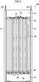
- the radiation panel (40) includes a pair of supports (41), a panel body (52) (also referred to as a "radiation heat exchanger (52)"), and a bottom plate (42).
- the supports (41) are provided at the left and right ends of the radiation panel (40), respectively. Each support (41) stands upright on the floor surface to extend vertically.
- the panel body (52) is provided between the pair of supports (41).
- the panel body (52) has its front face and rear face exposed to an indoor space.
- the bottom plate (42) extends laterally between the pair of supports (41) to be coupled to lower ends of the pair of supports (41).
- the bottom plate (42) is fixed to the floor surface of the room with fastening members (not shown), such as anchor bolts.
- Upper ends of the pair of supports (41) are connected to hanging bolts (not shown) on the ceiling via fixing portions (43).
- the radiation panel (40) forms a lower housing chamber (44) below the panel body (52).
- a drain pan (45) that collects condensation water generated on the panel body (52) is provided in the lower housing chamber (44).
- a front open face and rear open face of the lower housing chamber (44) are covered with lower covers (46), respectively.
- the lower covers (46) are detachably attached to, for example, lower portions of the pair of supports (41).
- the radiation panel (40) forms an upper housing chamber (47) above the panel body (52).
- the upper housing chamber (47) houses a liquid pipe (53) and gas pipe (54) of a refrigerant pipe.
- a radiation expansion valve (51) (not shown in FIG. 2 ) is connected to the liquid pipe (53).
- a front open face and rear open face of the upper housing chamber (47) are covered with upper covers (48), respectively.
- the upper covers (48) are detachably attached to, for example, upper portions of the pair of supports (41).
- the refrigerant circuit (11) includes an outdoor circuit (12), an indoor circuit (13), and a radiation circuit (15).
- the outdoor circuit (12) is provided in the outdoor unit (20), the indoor circuit (13) in the indoor unit (30), and the radiation circuit (15) in the radiation panel (40).
- the indoor unit (30) and the radiation panel (40) are connected to the outdoor unit (20) via two connection pipes (16, 17).
- the indoor circuit (13) and the radiation circuit (15) are connected to the outdoor circuit (12) via a gas connection pipe (16) and a liquid connection pipe (17) which are the connection pipes.
- the outdoor circuit (12) connects the compressor (21), the outdoor heat exchanger (22) (first heat exchanger), the outdoor expansion valve (23), and the four-way switching valve (24).
- the compressor (21) is configured as a variable capacity compressor. More specifically, an inverter device controls an operation frequency (number of rotations) of the compressor (21), so that the amount of the refrigerant circulating in the refrigerant circuit (11) can be adjusted.
- the outdoor fan (25) that transfers the outdoor air is provided near the outdoor heat exchanger (22).
- the outdoor heat exchanger (22) allows the refrigerant flowing therein to exchange heat with the outdoor air transferred by the outdoor fan (25).
- the outdoor expansion valve (23) is a flow rate control valve having a variable opening degree, and is constituted of, for example, an electronic expansion valve.
- the four-way switching valve (24) serves as a switching mechanism for switching between a heating operation and a cooling operation. Specifically, the four-way switching valve (24) is configured to be switchable between a first state (a state indicated by a solid line in FIG. 1 ) and a second state (a state indicated by a broken line in FIG. 1 ). The four-way switching valve (24) is switched to the first state in the cooling operation and a defrosting operation (will be described in detail later).
- the four-way switching valve (24) in the first state makes a discharge side of the compressor (21) and a gas end portion of the outdoor heat exchanger (22) to communicate with each other, and suction side of the compressor (21) and the gas connection pipe (16) to communicate with each other, in parallel.
- the four-way switching valve (24) is switched to the second state in the heating operation.
- the four-way switching valve (24) in the second state makes the discharge side of the compressor (21) and the gas connection pipe (16) to communicate with each other, the suction side of the compressor (21) and the gas end portion of the outdoor heat exchanger (22) to communicate with each other, in parallel.
- the outdoor circuit (12) is provided with a discharge pressure sensor (61) and a suction pressure sensor (62).
- the discharge pressure sensor (61) is arranged on the discharge side of the compressor (21).
- the discharge pressure sensor (61) detects the pressure of the refrigerant discharged from the compressor (21) (high pressure of the refrigerant circuit (11)).
- the suction pressure sensor (62) detects the pressure of the refrigerant to be sucked into the compressor (21) (low pressure of the refrigerant circuit (11)).
- the number of indoor circuits (13) corresponds to the number of indoor units (30).
- One end (liquid end portion) of the indoor circuit (13) is connected to the liquid connection pipe (17).
- the other end (gas end portion) of the indoor circuit (13) is connected to the gas connection pipe (16).
- the indoor expansion valve (32) and the indoor heat exchanger (31) (second heat exchanger) are connected in this order from the liquid end portion to gas end portion of the indoor circuit (13).
- the indoor expansion valve (32) is a flow rate control valve (first control valve) whose opening degree is variable, and is constituted of an electronic expansion valve, for example.
- the indoor fan (33) that transfers the indoor air is provided near the indoor heat exchanger (31).
- the indoor heat exchanger (31) allows the refrigerant flowing therein to exchange heat with the indoor air transferred by the indoor fan (33).
- the indoor circuit (13) is provided with a first liquid-side temperature sensor (63) and a first gas-side temperature sensor (64).
- the first liquid-side temperature sensor (63) is provided on a liquid side of the indoor heat exchanger (31), and detects the temperature of a liquid refrigerant flowing through the indoor circuit (13).
- the first gas-side temperature sensor (64) is provided on a gas side of the indoor heat exchanger (31), and detects the temperature of a gas refrigerant flowing through the indoor circuit (13).
- the number of radiation circuits (15) corresponds to the number of radiation panels (40).
- One end (liquid end portion) of the radiation circuit (15) is connected to the liquid connection pipe (17).
- the other end (gas end portion) of the radiation circuit (15) is connected to the gas connection pipe (16).
- the radiation expansion valve (51) and the radiation heat exchanger (52) are connected in this order from the liquid end portion to the gas end portion of the radiation circuit (15).
- the radiation expansion valve (51) is a flow rate control valve (second control valve) whose opening degree is variable, and is constituted of an electronic expansion valve, for example. No fan that transfers the air is provided near the radiation heat exchanger (52). That is, the radiation heat exchanger (52) exchanges heat between the refrigerant and the indoor air through the transfer of radiant heat.
- the radiation circuit (15) is provided with a second liquid-side temperature sensor (65) and a second gas-side temperature sensor (66).
- the second liquid-side temperature sensor (65) is provided on the liquid side (liquid pipe (53)) of the radiation heat exchanger (52), and detects the temperature of a liquid refrigerant flowing through the radiation circuit (15).
- the second gas-side temperature sensor (66) is provided on the gas side (gas pipe (54)) of the radiation heat exchanger (52), and detects the temperature of a gas refrigerant flowing through the radiation circuit (15).
- the indoor unit (30) of the present embodiment is provided with an indoor controller (CI), and the radiation panel (40) with a radiation controller (C2) (control unit).
- Each of the indoor controller (C1) and the radiation controller (C2) includes a microcomputer, and a memory device (specifically, a semiconductor memory) that stores software for operating the microcomputer.
- the indoor controller (C1) and the radiation controller (C2) can receive detection signals from various sensors, and can output control signals.
- the indoor controller (C1) controls start and stop (so-called thermo-on and thermo-off) of the indoor unit (30). More specifically, when a temperature Tr of the indoor air reaches a predetermined value according to a set temperature Ts, the indoor controller (C1) stops the indoor unit (30) (thermo-off).
- the indoor controller (C1) performs so-called superheat degree control on the opening degree of the indoor expansion valve (32).
- the opening degree of the indoor expansion valve (32) is regulated so that a degree of superheat SH1 of the refrigerant that has evaporated in the indoor heat exchanger (31) approaches a target degree of superheat.
- the degree of superheat SH1 is obtained, for example, from a difference between the temperature of the refrigerant detected by the first gas-side temperature sensor (64) and a saturation temperature corresponding to the low pressure detected by the suction pressure sensor (62).
- the indoor controller (C1) performs so-called subcooling degree control on the opening degree of the indoor expansion valve (32).
- the opening degree of the indoor expansion valve (32) is regulated so that a degree of subcooling SC1 of the refrigerant that has been condensed in the indoor heat exchanger (31) approaches a target degree of subcooling.
- the degree of subcooling SC1 is obtained, for example, from a difference between the temperature of the refrigerant detected by the first liquid-side temperature sensor (63) and a saturation temperature corresponding to the high pressure detected by the discharge pressure sensor (61).
- the indoor controller (C1) makes the indoor expansion valve (32) to open at a predetermined opening degree.
- the opening degree of the indoor expansion valve (32) at this time may be a predetermined fixed opening degree, or may suitably be regulated through the superheat degree control, for example. Accordingly, in the defrosting operation, the indoor heat exchanger (31) functions as an evaporator.
- the radiation controller (C2) performs so-called superheat degree control on the opening degree of the radiation expansion valve (51).
- the opening degree of the radiation expansion valve (51) is regulated so that a degree of superheat SH2 of the refrigerant that has evaporated in the radiation heat exchanger (52) approaches a target degree of superheat.
- the degree of superheat SH2 is obtained, for example, from a difference between the temperature of the refrigerant detected by the second gas-side temperature sensor (66) and the saturation temperature corresponding to the low pressure detected by the suction pressure sensor (62).
- the radiation controller (C2) performs so-called subcooling degree control on the opening degree of the radiation expansion valve (51).
- the opening degree of the radiation expansion valve (51) is regulated so that a degree of subcooling SC2 of the refrigerant that has been condensed in the radiation heat exchanger (52) approaches a target degree of subcooling.
- the degree of subcooling SC2 is obtained, for example, from a difference between the temperature of the refrigerant detected by the second liquid-side temperature sensor (65) and the saturation temperature corresponding to the high pressure detected by the discharge pressure sensor (61).
- the radiation controller (C2) controls the opening degree of the radiation expansion valve (51) in the defrosting operation and a preparatory operation performed immediately before the defrosting operation. Specifically, the radiation controller (C2) controls the radiation expansion valve (51) such that the radiation expansion valve (51) is always fully closed in the defrosting operation. In the preparatory operation, the radiation controller (C2) makes the radiation expansion valve (51) to open at a predetermined opening degree (will be described in detail later).
- the air conditioner (10) performs operation while switching between the cooling operation and the heating operation.
- the compressor (21), the outdoor fan (25), and the indoor fan (33) are operated.
- the four-way switching valve (24) is brought into the first state.
- the outdoor expansion valve (23) is opened at a predetermined opening degree (e.g., fully opened).
- the superheat degree control is performed on the opening degrees of the indoor expansion valve (32) and the radiation expansion valve (51).
- a refrigeration cycle is performed, in which the refrigerant that has been condensed and has dissipated heat in the outdoor heat exchanger (22) evaporates in the indoor heat exchanger (31) and the radiation heat exchanger (52) (i.e., the radiation panel (40)).
- the refrigerant compressed in the compressor (21) flows through the outdoor heat exchanger (22).
- the refrigerant dissipates heat to the outdoor air to be condensed.
- the refrigerant that has been condensed in the outdoor heat exchanger (22) passes through the outdoor expansion valve (23), and then flows through the liquid connection pipe (17).
- the refrigerant flowing through the liquid connection pipe (17) diverges into the indoor circuit (13) and the radiation circuit (15).
- the refrigerant that has flowed into the indoor circuit (13) is decompressed by the indoor expansion valve (32), and then flows through the indoor heat exchanger (31).
- the indoor heat exchanger (31) the refrigerant absorbs heat from the air transported by the indoor fan (33) to evaporate.
- the refrigerant evaporated in the indoor heat exchanger (31) flows into the gas connection pipe (16).
- the refrigerant that has flowed into the radiation circuit (15) is decompressed by the radiation expansion valve (51), and then flows through the radiation heat exchanger (52).
- the radiation heat exchanger (52) the refrigerant absorbs heat from the indoor air around the radiation panel (40) to evaporate.
- the refrigerant evaporated in the radiation heat exchanger (52) flows into the gas connection pipe (16).
- the compressor (21), the outdoor fan (25), and the indoor fan (33) are operated.
- the four-way switching valve (24) is brought into the second state.
- the superheat degree control is performed on the outdoor expansion valve (23).
- the subcooling degree control is performed on the opening degrees of the indoor expansion valve (32) and the radiation panel (40).
- a refrigeration cycle is performed, in which the refrigerant that has been condensed and has dissipated heat in the indoor heat exchanger (31) and the radiation heat exchanger (52) evaporates in the outdoor heat exchanger (22).
- the refrigerant compressed in the compressor (21) flows through the gas connection pipe (16), and diverges into the outdoor circuit (12) and the radiation circuit (15).
- the refrigerant that has flowed into the indoor circuit (13) flows through the indoor heat exchanger (31).
- the refrigerant dissipates heat into the air transported by the indoor fan (33) to be condensed.
- the refrigerant that has been condensed in the indoor heat exchanger (31) passes through the indoor expansion valve (32), and then flows into the liquid connection pipe (17).
- the refrigerant dissipates heat into the indoor air around the radiation panel (40) to be condensed.
- the refrigerant condensed in the radiation heat exchanger (52) passes through the radiation expansion valve (51), and then flows into the liquid connection pipe (17).
- the flows of the refrigerant merge together in the liquid connection pipe (17), which flows into the outdoor circuit (12), is decompressed by the outdoor expansion valve (23), and then flows through the outdoor heat exchanger (22).
- the refrigerant absorbs heat from the outdoor air to evaporate.
- the refrigerant evaporated in the outdoor heat exchanger (22) is sucked into the compressor (21), and is compressed again.
- the surface of the outdoor heat exchanger (22) serving as an evaporator may be frosted.
- the air conditioner (10) is configured to be able to perform a defrosting operation for defrosting the outdoor heat exchanger (22).
- the refrigerant dissipates heat and is condensed in the outdoor heat exchanger (22), and a refrigeration cycle (defrosting cycle) in which the refrigerant evaporates in the indoor heat exchanger (31) is performed.
- the preparatory operation is executed before switching from the heating operation to the defrosting operation.
- oil accumulated in the radiation panel (40) is discharged together with the liquid refrigerant. The preparatory operation and the defrosting operation will be described in detail with reference to FIGS. 1 and 3 .
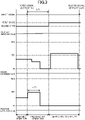
- a condition A indicating that the surface of the outdoor heat exchanger (22) is frosted a first signal for executing the defrosting operation is inputted to each controller (C1, C2). Then, the preparatory operation for shifting from the heating operation to the defrosting operation starts. The preparatory operation is performed until a predetermined time ⁇ T1 elapses after the input of the first signal, and the operation is then shifted to the defrosting operation.
- Whether the condition A is satisfied or not is determined based on, for example, the temperature of the refrigerant flowing through the outdoor heat exchanger (22), the temperature of the air passing through the outdoor heat exchanger (22), and the duration of the heating operation.
- the number of rotations of the compressor (21) decreases stepwise.
- the compressor (21) stops operating before the defrosting operation starts.
- the opening degree of the indoor expansion valve (32) also decreases as the number of rotations of the compressor (21) decreases.
- the opening degree of the indoor expansion valve (32) may be controlled through the subcooling degree control, or through gradually reducing the target opening degree of the indoor expansion valve (32).
- the four-way switching valve (24) is kept unchanged from the state (the second state) during the heating operation. Therefore, the refrigerant flows basically in the same way as in the heating operation.
- the radiation controller (C2) brings the radiation expansion valve (51) to open at a predetermined opening degree (first opening degree) in synchronization with the first signal.
- a predetermined opening degree first opening degree
- the first opening degree of the present embodiment is set to an opening degree of 50% (e.g., about 1000 pulses).
- the oil (refrigerating machine oil) can be reliably discharged from the radiation panel (40). This can avoid lubrication failure of the compressor (21) in the subsequent defrosting operation.
- the radiation expansion valve (51) When time ⁇ T2 (e.g., 40 seconds) has elapsed after the change of the opening degree of the radiation expansion valve (51) to the first opening degree, the radiation expansion valve (51) is fully closed. Time ⁇ T2 is shorter than time ⁇ T1. Accordingly, the radiation expansion valve (51) is fully closed after the opening degree is changed to the first opening degree and before the defrosting operation starts.
- the opening degree corresponding to the "fully closed" state refers to an opening degree at which substantially no refrigerant flows inside the radiation panel (40), and is not necessarily limited to the opening degree of zero pulse.
- the defrosting operation is performed. Then, the four-way switching valve (24) is switched from the second state to the first state.
- the defrosting operation starts, the number of rotations of the compressor (21) gradually increases to a target number of rotations.
- the indoor expansion valve (32) is opened at a predetermined opening degree.
- the indoor expansion valve (32) may be subjected to the superheat degree control, or the opening degree thereof may be regulated to a predetermined target opening degree.
- the outdoor expansion valve (23) is fully opened, for example.
- the radiation expansion valve (51) is controlled to be fully closed.
- the radiation expansion valve (51) is fully closed immediately before the start of the defrosting operation.
- the target opening degree (e.g., zero pulse) of the radiation expansion valve (51) is kept unchanged.
- the radiation expansion valve (51) is controlled to be always fully closed. Specifically, during the entire period of the defrosting operation, the target opening degree of the radiation expansion valve (51) is maintained at a value that keeps the fully closed state. Note that the target opening degree of the radiation expansion valve (51) may be changed to the value that keeps the fully closed state at the same timing as the start of the defrosting operation.
- the following refrigeration cycle (defrosting cycle) is basically performed.
- the refrigerant compressed in the compressor (21) flows through the outdoor heat exchanger (22).
- the refrigerant dissipates heat to the frost on the surface of the outdoor heat exchanger (22).
- the frost on the outdoor heat exchanger (22) melts.
- the refrigerant that has dissipated heat and has been condensed in the outdoor heat exchanger (22) flows through the liquid connection pipe (17).
- the indoor expansion valve (32) is opened at a predetermined opening degree. Therefore, the refrigerant in the liquid connection pipe (17) is decompressed by the indoor expansion valve (32), and then evaporates in the indoor heat exchanger (31). The evaporated refrigerant flows through the gas connection pipe (16), and then is sucked into the compressor (21).
- the radiation expansion valve (51) is fully closed. Therefore, the refrigerant in the liquid connection pipe (17) is not sent to the radiation circuit (15) or the radiation panel (40) (the radiation heat exchanger (52)). If the refrigerant flows inside the radiation panel (40) in the defrosting operation, the refrigerant evaporates in the radiation panel (40). In this case, the surface temperature of the panel body (52) is lowered, thereby increasing a heating load of the indoor space. Further, a person in the room feels cold when he or she touches the panel body (52).
- the radiation expansion valve (51) is fully closed during the entire period of the defrosting operation.
- the radiation panel (40) can be reliably avoided from being cooled due to the evaporation of the refrigerant. This can reliably avoid the heating load from increasing, or the comfort of the person in the room from being impaired.
- the radiation expansion valve (51) is brought to open at the first opening degree in the preparatory operation. This allows the oil accumulated inside the radiation panel (40) to be discharged together with the refrigerant. Therefore, in the defrosting operation, a sufficient amount of oil can be maintained, thereby avoiding the lubrication failure of the compressor (21).
- a condition B indicating that the defrosting of the outdoor heat exchanger (22) is completed is satisfied during the defrosting operation
- a second signal for ending the defrosting operation is inputted to each controller (C1, C2). Then, the defrosting operation is shifted to the normal operation (heating operation). Whether the condition B is satisfied or not is determined based on, for example, the temperature of the refrigerant flowing through the outdoor heat exchanger (22), the temperature of the air passing through the outdoor heat exchanger (22), and the duration of the defrosting operation.
- the radiation expansion valve (51) is always fully closed during the defrosting operation. This can reliably avoid the refrigerant from evaporating in the radiation panel (40).
- the evaporation of the refrigerant in the indoor heat exchanger (31), which is present inside the indoor unit (30), does not have a great influence on the temperature of the indoor space.
- the influence on the indoor temperature is significantly reduced if the indoor fan (33) is stopped.
- the radiation panel (40) is placed on the floor surface of the indoor space, and the panel body (52) is configured to be exposed to the indoor space.
- the radiation panel (40) serves as an evaporator, the radiation tends to lower the temperature of the ambient air around the person in the room.
- the radiation panel (40) since the radiation panel (40) is within the reach of the person in the room, the person, if touches the radiation panel (40), may feel it cold and uncomfortable.
- the ambient temperature of the radiation panel (40) can be reliably avoided from decreasing, and the person in the room from feeling uncomfortable.
- the radiation expansion valve (51) is brought to open at the first opening degree before the defrosting cycle starts. Specifically, receiving a signal (first signal) for executing the defrosting operation, the control unit (indoor controller (C1)) brings the radiation expansion valve (51) to open at the first opening degree before the defrosting operation starts. This allows the oil in the radiation panel (40) to be discharged and sent to the compressor (21). During the defrosting operation, the radiation expansion valve (51) is always fully closed, and thus, no refrigerant flows inside the radiation panel (40). However, since the oil is discharged from the radiation panel (40) as described above, the lubrication failure of the compressor (21) during the defrosting cycle can be avoided.
- the first opening degree is smaller than the maximum opening degree of the radiation expansion valve (51). If the opening degree of the radiation expansion valve (51) is too large, a larger amount of refrigerant flows through the radiation expansion valve (51), and the sound of the refrigerant passing through the valve may become noisy. Such noise can be reduced through making the opening degree of the radiation expansion valve (51) smaller than the maximum opening degree.
- the first opening degree is equal to or greater than 50% of the maximum opening degree of the radiation expansion valve (51).
- the oil can be reliably discharged from the radiation panel (40) during the preparatory period.
- FIG. 4 illustrates a first variation, in which the control in the preparatory operation is different from that of the above embodiment.
- the opening degree of the radiation expansion valve (51) is changed stepwise when the first signal is inputted. Specifically, receiving the first signal, the radiation controller (C2) changes the target opening degree of the radiation expansion valve (51) stepwise to be closer to a final target opening degree (first opening degree). As a result, the opening degree of the radiation expansion valve (51) gradually changes to converge to the first opening degree. Then, after time ⁇ T2 has elapsed, the radiation expansion valve (51) is fully closed.
- the opening degree of the radiation expansion valve (51) changes stepwise, which can keep the opening degree of the radiation expansion valve (51) from increasing abruptly. If the opening degree of the radiation expansion valve (51) abruptly increases, a large amount of liquid refrigerant passes through the radiation expansion valve (51), which may cause noise. On the other hand, if the radiation expansion valve (51) is gradually opened, the flow rate of the refrigerant that instantaneously flows through the radiation expansion valve (51) can be reduced. In addition, gradually increasing the opening degree of the radiation expansion valve (51) in this way makes it possible to gradually reduce the degree of subcooling of the refrigerant flowing through the radiation panel (40) in the preparatory operation, and the refrigerant can be brought into a gas-liquid two-phase state.
- the opening degree of the radiation expansion valve (51) is suitably changed stepwise so that the refrigerant has a degree of subcooling of 5°C or lower. Further, the target opening degree may be substantially changed in a linear fashion through shortening the period for which the target opening degree is changed stepwise.
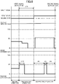
- FIG. 5 illustrates a second variation, in which the control is different from that of the above embodiment.
- a condition A indicating that the surface of the outdoor heat exchanger (22) is frosted a first signal for executing the defrosting operation is inputted to each controller (C1, C2). Then, the preparatory operation for shifting from the heating operation to the defrosting operation starts. The preparatory operation is performed until a predetermined time ⁇ T1 elapses after the input of the first signal, and the operation is then shifted to the defrosting operation.
- Whether the condition A is satisfied or not is determined based on, for example, the temperature of the refrigerant flowing through the outdoor heat exchanger (22), the temperature of the air passing through the outdoor heat exchanger (22), and the duration of the heating operation.
- the number of rotations of the compressor (21) decreases stepwise.
- the compressor (21) stops operating before the defrosting operation starts.
- the opening degree of the indoor expansion valve (32) also decreases as the number of rotations of the compressor (21) decreases.
- the opening degree of the indoor expansion valve (32) may be controlled through the subcooling degree control, or through gradually reducing the target opening degree of the indoor expansion valve (32).
- the four-way switching valve (24) is kept unchanged from the state (the second state) during the heating operation. Therefore, the refrigerant flows basically in the same way as in the heating operation.
- the radiation controller (C2) performs control of reducing the opening degree of the radiation expansion valve (51) with the decrease in the number of rotations of the compressor (21).
- the opening degree of the radiation expansion valve (51) may be controlled through the subcooling degree control, or through gradually reducing the target opening degree of the indoor expansion valve (32).
- the defrosting operation is performed. Then, the four-way switching valve (24) is switched from the second state to the first state.
- the defrosting operation starts, the number of rotations of the compressor (21) gradually increases to a target number of rotations.
- the indoor expansion valve (32) is opened at a predetermined opening degree.
- the indoor expansion valve (32) may be subjected to the superheat degree control, or the opening degree thereof may be regulated to a predetermined target opening degree.
- the outdoor expansion valve (23) is fully opened, for example.
- the radiation controller (C2) temporarily opens the radiation expansion valve (51), and during the remaining period, the radiation controller (C2) brings the radiation expansion valve (51) to be fully closed.
- the radiation expansion valve (51) is controlled to be fully closed in some periods (periods P1 and P3 in FIG. 3 ), and to be open in the other period (period P2 in FIG. 3 ).
- the opening degree corresponding to the "fully closed" state refers to an opening degree at which substantially no refrigerant flows inside the radiation panel (40), and is not necessarily limited to the opening degree of zero pulse.
- the following refrigeration cycle (defrosting cycle) is basically performed.
- the refrigerant compressed in the compressor (21) flows through the outdoor heat exchanger (22).
- the refrigerant dissipates heat to the frost on the surface of the outdoor heat exchanger (22).
- the frost on the outdoor heat exchanger (22) melts.
- the refrigerant that has dissipated heat and has been condensed in the outdoor heat exchanger (22) flows through the liquid connection pipe (17).
- the indoor expansion valve (32) is opened at a predetermined opening degree. Therefore, the refrigerant in the liquid connection pipe (17) is decompressed by the indoor expansion valve (32), and then evaporates in the indoor heat exchanger (31). The evaporated refrigerant flows through the gas connection pipe (16), and then is sucked into the compressor (21).
- the radiation expansion valve (51) is fully closed. Therefore, the refrigerant in the liquid connection pipe (17) is not sent to the radiation circuit (15) or the radiation panel (40) (the radiation heat exchanger (52)). If the refrigerant flows inside the radiation panel (40), the refrigerant evaporates in the radiation panel (40). In this case, the surface temperature of the panel body (52) is lowered, thereby increasing a heating load of the indoor space. Further, a person in the room feels cold when he or she touches the panel body (52).
- the radiation expansion valve (51) since the radiation expansion valve (51) is fully closed during the periods P1 and P3, the radiation panel (40) can be reliably avoided from being cooled due to the evaporation of the refrigerant. This can reliably avoid the heating load from increasing, or the comfort of the person in the room from being impaired.
- the radiation expansion valve (51) is fully closed for the entire period of the defrosting operation, oil (refrigerating machine oil) accumulates in the radiation expansion valve (51), which may result in a shortage of oil returning to the compressor (21).
- the radiation expansion valve (51) is opened at a second opening degree for a certain period (period P2). Therefore, in the period P2, the oil accumulated in the radiation panel (40) can be discharged together with the refrigerant.
- a sufficient amount of oil can be maintained, thereby avoiding the lubrication failure of the compressor (21).
- the second opening degree of the present embodiment is set to an opening degree of 50% (e.g., about 1000 pulses). Setting the opening degree of the radiation expansion valve (51) to equal to or greater than 50% of the maximum opening degree allows the oil to be sufficiently discharged from the radiation panel (40).
- a condition B indicating that the defrosting of the outdoor heat exchanger (22) is completed is satisfied during the defrosting operation
- a second signal for ending the defrosting operation is inputted to each controller (C1, C2). Then, the defrosting operation is shifted to the normal operation (heating operation). Whether the condition B is satisfied or not is determined based on, for example, the temperature of the refrigerant flowing through the outdoor heat exchanger (22), the temperature of the air passing through the outdoor heat exchanger (22), and the duration of the defrosting operation.
- the radiation expansion valve (51) is fully closed in some periods (the periods P1 and P3) in the defrosting operation, and is opened in the other period (the period P2). Therefore, the evaporation of the refrigerant in the radiation panel (40) can be reliably avoided in the periods P1 and P3, and the oil can be reliably discharged from the radiation panel (40) in the period P2.
- the evaporation of the refrigerant in the indoor heat exchanger (31), which is present inside the indoor unit (30), does not have a great influence on the temperature of the indoor space.
- the influence on the indoor temperature is significantly reduced if the indoor fan (33) is stopped.
- the radiation panel (40) is placed on the floor surface of the indoor space, and the panel body (52) is configured to be exposed to the indoor space.
- the radiation panel (40) serves as an evaporator, the radiation tends to lower the temperature of the ambient air around the person in the room.
- the radiation panel (40) since the radiation panel (40) is within the reach of the person in the room, the person, if touches the radiation panel (40), may feel it cold and uncomfortable.
- the ambient temperature of the radiation panel (40) can be reliably avoided from decreasing, and the person in the room from feeling uncomfortable, in the periods P1 and P3.
- the oil in the radiation panel (40) can be discharged and sent to the compressor (21).
- the lubrication failure of the compressor (21) during the defrosting cycle can be avoided.
- the second opening degree is smaller than the maximum opening degree of the radiation expansion valve (51). If the opening degree of the radiation expansion valve (51) is too large, a larger amount of refrigerant flows through the radiation expansion valve (51), and the sound of the refrigerant passing through the valve may become noisy. Such noise can be reduced through making the opening degree of the radiation expansion valve (51) smaller than the maximum opening degree.
- the second opening degree is equal to or greater than 50% of the maximum opening degree of the radiation expansion valve (51).
- the oil can be reliably discharged from the radiation panel (40).
- FIG. 6 illustrates a third variation, in which the control is different from that of the above embodiment.
- the radiation controller (C2) brings the radiation expansion valve (51) to open at a predetermined opening degree (first opening degree) in synchronization with the first signal.
- a predetermined opening degree first opening degree
- the maximum opening degree of the radiation expansion valve (51) is 100% (e.g., about 2000 pulses)
- the first opening degree according to the third variation is set to an opening degree of 50% (e.g., about 1000 pulses).
- the oil (refrigerating machine oil) can be reliably discharged from the radiation panel (40). This can avoid lubrication failure of the compressor (21) in the subsequent defrosting operation.
- the radiation expansion valve (51) is made to open at the first opening degree before the defrosting cycle starts. This allows the oil in the radiation panel (40) to be discharged and sent to the compressor (21) before the defrosting operation. Thus, the lubrication failure of the compressor (21) during the defrosting cycle can be reliably avoided.
- the first opening degree is smaller than the maximum opening degree of the radiation expansion valve (51). If the opening degree of the radiation expansion valve (51) is too large, a larger amount of refrigerant flows through the radiation expansion valve (51), and the sound of the refrigerant passing through the valve may become noisy. Such noise can be reduced through making the opening degree of the radiation expansion valve (51) smaller than the maximum opening degree.
- the first opening degree is equal to or greater than 50% of the maximum opening degree of the radiation expansion valve (51).
- the oil can be reliably discharged from the radiation panel (40) during the preparatory period.
- FIG. 7 illustrates a fourth variation, in which the control is different from that of the above embodiment.
- the opening degree of the radiation expansion valve (51) is changed stepwise when the first signal is inputted. Specifically, receiving the first signal, the radiation controller (C2) changes the target opening degree of the radiation expansion valve (51) stepwise to be closer to a final target opening degree (first opening degree). As a result, the opening degree of the radiation expansion valve (51) gradually changes to converge to the first opening degree. Then, after time ⁇ T2 has elapsed, the radiation expansion valve (51) is fully closed.
- the opening degree of the radiation expansion valve (51) changes stepwise, which can keep the opening degree of the radiation expansion valve (51) from increasing abruptly. If the opening degree of the radiation expansion valve (51) abruptly increases, a large amount of liquid refrigerant passes through the radiation expansion valve (51), which may cause noise. On the other hand, if the radiation expansion valve (51) is gradually opened, the flow rate of the refrigerant that instantaneously flows through the radiation expansion valve (51) can be reduced. In addition, gradually increasing the opening degree of the radiation expansion valve (51) in this way makes it possible to gradually reduce the degree of subcooling of the refrigerant flowing through the radiation panel (40) in the preparatory operation, and the refrigerant can be brought into a gas-liquid two-phase state.
- the opening degree of the radiation expansion valve (51) is suitably changed stepwise so that the refrigerant has a degree of subcooling of 5°C or lower. Further, the target opening degree may be substantially changed in a linear fashion through shortening the period for which the target opening degree is changed stepwise.
- the radiation expansion valve (51) is opened in some periods (two periods P2 and P4 in this variation) in the defrosting operation.
- the radiation expansion valve (51) is opened at a second opening degree (e.g., 50% of the maximum opening degree).
- the radiation expansion valve (51) is opened at an opening degree greater than the second opening degree.
- the radiation expansion valve (51) may be opened at the first opening degree in a certain period, and at an opening degree different from the first opening angle in a different period.
- the air conditioner (10) of the above-described embodiment performs the heating operation in which all of the indoor heat exchanger (31) and the radiation panel (40) serve as radiators, and the cooling operation in which all of the indoor heat exchanger (31) and the radiation panel (40) serve as evaporators.
- the air conditioner (10) may be configured as a system (a so-called simultaneous cooling/heating system) that performs the cooling operation simultaneously by using one of the indoor heat exchanger (31) or the radiation panel (40) as an evaporator, and the other as a condenser.
- the number of the connection pipes may be two or three.
- the air conditioner (10) may be configured as a system in which the radiation panel (40) (strictly speaking, the radiation heat exchanger (52)) and the indoor heat exchanger (31)) are housed in a single unit (e.g., a floor type unit).
- the air conditioner (10) may have no indoor heat exchanger (31), and may include a heat exchanger (first heat exchanger) dedicated to the defrosting operation.
- a heat exchanger first heat exchanger dedicated to the defrosting operation.
- a refrigeration cycle is performed in which the outdoor heat exchanger (22) serves as a radiator, and the radiation panel (40) as an evaporator.
- a refrigeration cycle is performed in which the radiation panel (40) serves as a radiator, and the outdoor heat exchanger (22) as an evaporator.
- a refrigeration cycle (defrosting cycle) is performed in which the outdoor heat exchanger (22) (first heat exchanger) serves as a radiator, and the heat exchanger (second heat exchanger) dedicated to the defrosting operation as an evaporator.
- the indoor unit (30) which is mounted on the ceiling (strictly speaking, hung from or embedded in the ceiling), may be replaced with an indoor unit placed on the floor surface or mounted on a wall surface.
- the radiation panel (40), which is placed on the floor surface, may be replaced with a radiation panel mounted on the ceiling or the wall surface.
- the present disclosure is useful for an air conditioner.
Description
- The present invention relates to an air conditioner.
-
JP 2015025627 A -
EP 3 054 230 A1 discloses an air conditioner with an outdoor unit, an indoor unit and a controller which controller is capable of controlling an outdoor fan.EP 3 040 635 A1 discloses an air conditioner with a defrosting function.EP 2 309 199 A1 discloses a multiple air conditioner for buildings.EP 2 863 153 A1 discloses an air conditioner with an outdoor heat exchanger, an indoor heat exchanger and a heat storage heat exchanger. - In an air conditioner equipped with a radiation panel, an operation of defrosting a heat exchanger (e.g., an outdoor heat exchanger) can be performed. Specifically, for example, it is conceivable to perform a defrosting cycle in which a refrigerant compressed in a compressor dissipates heat in an outdoor heat exchanger, and the refrigerant that has dissipated heat evaporates in the radiation panel and an indoor heat exchanger, in parallel. In this defrosting cycle, the refrigerant absorbs heat from the ambient air to be evaporated in the radiation panel. This has been disadvantageous because the air around the radiation panel (e.g., the air in an indoor space) is cooled.
- It is an object of the present invention to provide an air conditioner capable of keeping a radiation panel from cooling the air in a defrosting cycle.
- A first aspect of the current invention is directed to an air conditioner including: a refrigerant circuit (11) connecting a compressor (21), a first heat exchanger (22), a second heat exchanger (31), a radiation panel (40) in parallel to the second heat exchanger (31), a first expansion valve (51) that regulates a flow rate of a refrigerant flowing through the radiation panel (40), a four-way switching valve (24), and a second expansion valve (32) that regulates a flow rate of refrigerant flowing through the second heat exchanger (31) and a control unit (C1) that switches between a normal refrigeration cycle in which the radiation panel (40) performs cooling or heating, and a defrosting cycle in which the first heat exchanger (22) serves as a radiator and the second heat exchanger (31) serves as an evaporator, wherein the control unit (C1) brings the first expansion valve (51) to be fully closed during the defrosting cycle and the control unit (C1) brings the first expansion valve (51) to open at a first opening degree in a preparatory operation performed immediately before the defrosting cycle starts.
- According to the first aspect, the refrigerant can be kept from flowing inside the radiation panel (40) during the defrosting cycle. This makes it possible to defrost a surface of the first heat exchanger (22), while avoiding the radiation panel (40) from serving as an evaporator. Also, in the first aspect, the first expansion valve (51) is opened before the defrosting cycle starts. Thus, oil can be discharged from the radiation panel (40) before the defrosting cycle starts. This can avoid a shortage of oil returning to the compressor (21) during the defrosting cycle.
- A second aspect is an embodiment of the first embodiment. In the second aspect, the control unit (C1) brings the first expansion valve (51) to be always fully closed during the defrosting cycle. Note that the control unit "brings the expansion valve to be always fully closed" means that control is performed so that the expansion valve (51) is always fully closed. Therefore, for example, even if the expansion valve (51) is not actually fully closed immediately after the start of a defrosting operation due to a delay in response although the control unit attempts to cause the expansion valve (51) to be fully closed at the start of the defrosting operation, this state is also included in the "always fully closed" state recited in claim 1.
- In the second aspect, the refrigerant can be kept from flowing inside the radiation panel (40) during the entire period of the defrosting cycle. This makes it possible to defrost a surface of the first heat exchanger (22), while avoiding the radiation panel (40) from serving as an evaporator.
- A third aspect is an embodiment of the third aspect. In the fourth aspect, the first opening degree is smaller than a maximum opening degree of the first expansion valve (51).
- In the third aspect, the sound of the refrigerant passing through the expansion valve (51) can be kept from becoming noisy due to an excessively large opening degree of the first expansion valve (51).
- A fourth aspect is an embodiment of the fourth aspect. In the fifth aspect, the first opening degree is equal to or greater than 50% of the maximum opening degree of the first expansion valve (51).
- In the fourth aspect, a shortage of oil returning to the compressor (21) due to an excessively small opening degree of the first expansion valve (51) can be avoided.
- A fifth aspect is an embodiment of any one of the third to fifth aspects. In the sixth aspect, the control unit (C1) changes an opening degree of the first expansion valve (51) stepwise to the first opening degree in the preparatory operation performed immediately before the defrosting cycle starts.
- In the fifth aspect, the sound of the refrigerant passing through the expansion valve (51) can be kept from becoming noisy due to an abrupt increase in the opening degree of the first expansion valve (51).
- A sixth aspect is an embodiment of any one of the first to fifth aspects. In the seventh aspect, the first heat exchanger (22) is provided in an indoor unit (30), and the second heat exchanger (31) is provided in an outdoor unit (20).
-
- [
FIG. 1] FIG. 1 is a piping system diagram illustrating a schematic configuration of an air conditioner according to an embodiment of the current invention. - [
FIG. 2] FIG. 2 is a front view illustrating a schematic configuration of a radiation panel according to an embodiment of the current invention. - [
FIG. 3] FIG. 3 is a timing chart illustrating how a four-way switching valve, an indoor expansion valve, and a radiation expansion valve are operated in a preparatory operation and a defrosting according to an embodiment of the current invention.Figures 4-8 show variations according tofigure 3 according to embodiments of the current invention. - [
FIG. 4] FIG. 4 is a view corresponding toFIG. 3 , according to a first variation. - [
FIG. 5] FIG. 5 is a view corresponding toFIG. 3 , according to a second variation. - [
FIG. 6] FIG. 6 is a view corresponding toFIG. 3 , according to a third variation. - [
FIG. 7] FIG. 7 is a view corresponding toFIG. 3 , according to a fourth variation. - [
FIG. 8] FIG. 8 is a view corresponding toFIG. 3 , according to a fifth variation. - An air conditioner (10) of the present embodiment will be described with reference to the drawings.
- The air conditioner (10) performs switching between cooling and heating of a room. As shown in
FIG. 1 , the air conditioner (10) includes an outdoor unit (20), an indoor unit (30), and a radiation panel (40). - The outdoor unit (20) is placed outside. The outdoor unit (20) constitutes a heat source unit. The outdoor unit (20) is provided with a compressor (21), an outdoor heat exchanger (22), an outdoor expansion valve (23), a four-way switching valve (24), and an outdoor fan (25).
- The indoor unit (30) is provided near a ceiling of the room. The indoor unit (30) constitutes a convection indoor unit that performs cooling or heating with the air transported by an indoor fan (33). The indoor unit (30) includes a single indoor unit, or two or more indoor units. Each indoor unit (30) is provided with an indoor heat exchanger (31), an indoor expansion valve (32), and an indoor fan (33).
- The radiation panel (40) is placed on a floor surface of the room. The radiation panel (40) constitutes a radiant indoor unit that performs cooling or heating by the transfer of radiant heat. The radiation panel (40) includes a single radiation panel, or two or more radiation panels.
- The air conditioner (10) includes a refrigerant circuit (11) which is filled with a refrigerant and allows the refrigerant to circulate therein. The refrigerant circuit (11) will be described in detail later.
- A general configuration of the radiation panel (40) will be described with reference to
FIG. 2 . The radiation panel (40) includes a pair of supports (41), a panel body (52) (also referred to as a "radiation heat exchanger (52)"), and a bottom plate (42). - The supports (41) are provided at the left and right ends of the radiation panel (40), respectively. Each support (41) stands upright on the floor surface to extend vertically.
- The panel body (52) is provided between the pair of supports (41). The panel body (52) has its front face and rear face exposed to an indoor space.
- The bottom plate (42) extends laterally between the pair of supports (41) to be coupled to lower ends of the pair of supports (41). The bottom plate (42) is fixed to the floor surface of the room with fastening members (not shown), such as anchor bolts. Upper ends of the pair of supports (41) are connected to hanging bolts (not shown) on the ceiling via fixing portions (43).
- The radiation panel (40) forms a lower housing chamber (44) below the panel body (52). A drain pan (45) that collects condensation water generated on the panel body (52) is provided in the lower housing chamber (44). A front open face and rear open face of the lower housing chamber (44) are covered with lower covers (46), respectively. The lower covers (46) are detachably attached to, for example, lower portions of the pair of supports (41).
- The radiation panel (40) forms an upper housing chamber (47) above the panel body (52). The upper housing chamber (47) houses a liquid pipe (53) and gas pipe (54) of a refrigerant pipe. A radiation expansion valve (51) (not shown in
FIG. 2 ) is connected to the liquid pipe (53). A front open face and rear open face of the upper housing chamber (47) are covered with upper covers (48), respectively. The upper covers (48) are detachably attached to, for example, upper portions of the pair of supports (41). - The configuration of the refrigerant circuit (11) will be described in more detail with reference to
FIG. 1 . The refrigerant circuit (11) includes an outdoor circuit (12), an indoor circuit (13), and a radiation circuit (15). The outdoor circuit (12) is provided in the outdoor unit (20), the indoor circuit (13) in the indoor unit (30), and the radiation circuit (15) in the radiation panel (40). In the present embodiment, the indoor unit (30) and the radiation panel (40) are connected to the outdoor unit (20) via two connection pipes (16, 17). Strictly speaking, the indoor circuit (13) and the radiation circuit (15) are connected to the outdoor circuit (12) via a gas connection pipe (16) and a liquid connection pipe (17) which are the connection pipes. - The outdoor circuit (12) connects the compressor (21), the outdoor heat exchanger (22) (first heat exchanger), the outdoor expansion valve (23), and the four-way switching valve (24). The compressor (21) is configured as a variable capacity compressor. More specifically, an inverter device controls an operation frequency (number of rotations) of the compressor (21), so that the amount of the refrigerant circulating in the refrigerant circuit (11) can be adjusted. The outdoor fan (25) that transfers the outdoor air is provided near the outdoor heat exchanger (22). The outdoor heat exchanger (22) allows the refrigerant flowing therein to exchange heat with the outdoor air transferred by the outdoor fan (25). The outdoor expansion valve (23) is a flow rate control valve having a variable opening degree, and is constituted of, for example, an electronic expansion valve.
- The four-way switching valve (24) serves as a switching mechanism for switching between a heating operation and a cooling operation. Specifically, the four-way switching valve (24) is configured to be switchable between a first state (a state indicated by a solid line in
FIG. 1 ) and a second state (a state indicated by a broken line inFIG. 1 ). The four-way switching valve (24) is switched to the first state in the cooling operation and a defrosting operation (will be described in detail later). The four-way switching valve (24) in the first state makes a discharge side of the compressor (21) and a gas end portion of the outdoor heat exchanger (22) to communicate with each other, and suction side of the compressor (21) and the gas connection pipe (16) to communicate with each other, in parallel. The four-way switching valve (24) is switched to the second state in the heating operation. The four-way switching valve (24) in the second state makes the discharge side of the compressor (21) and the gas connection pipe (16) to communicate with each other, the suction side of the compressor (21) and the gas end portion of the outdoor heat exchanger (22) to communicate with each other, in parallel. - The outdoor circuit (12) is provided with a discharge pressure sensor (61) and a suction pressure sensor (62). The discharge pressure sensor (61) is arranged on the discharge side of the compressor (21). The discharge pressure sensor (61) detects the pressure of the refrigerant discharged from the compressor (21) (high pressure of the refrigerant circuit (11)). The suction pressure sensor (62) detects the pressure of the refrigerant to be sucked into the compressor (21) (low pressure of the refrigerant circuit (11)).
- The number of indoor circuits (13) corresponds to the number of indoor units (30). One end (liquid end portion) of the indoor circuit (13) is connected to the liquid connection pipe (17). The other end (gas end portion) of the indoor circuit (13) is connected to the gas connection pipe (16). In the indoor circuit (13), the indoor expansion valve (32) and the indoor heat exchanger (31) (second heat exchanger) are connected in this order from the liquid end portion to gas end portion of the indoor circuit (13). The indoor expansion valve (32) is a flow rate control valve (first control valve) whose opening degree is variable, and is constituted of an electronic expansion valve, for example. The indoor fan (33) that transfers the indoor air is provided near the indoor heat exchanger (31). The indoor heat exchanger (31) allows the refrigerant flowing therein to exchange heat with the indoor air transferred by the indoor fan (33).
- The indoor circuit (13) is provided with a first liquid-side temperature sensor (63) and a first gas-side temperature sensor (64). The first liquid-side temperature sensor (63) is provided on a liquid side of the indoor heat exchanger (31), and detects the temperature of a liquid refrigerant flowing through the indoor circuit (13). The first gas-side temperature sensor (64) is provided on a gas side of the indoor heat exchanger (31), and detects the temperature of a gas refrigerant flowing through the indoor circuit (13).
- The number of radiation circuits (15) corresponds to the number of radiation panels (40). One end (liquid end portion) of the radiation circuit (15) is connected to the liquid connection pipe (17). The other end (gas end portion) of the radiation circuit (15) is connected to the gas connection pipe (16). In the radiation circuit (15), the radiation expansion valve (51) and the radiation heat exchanger (52) are connected in this order from the liquid end portion to the gas end portion of the radiation circuit (15). The radiation expansion valve (51) is a flow rate control valve (second control valve) whose opening degree is variable, and is constituted of an electronic expansion valve, for example. No fan that transfers the air is provided near the radiation heat exchanger (52). That is, the radiation heat exchanger (52) exchanges heat between the refrigerant and the indoor air through the transfer of radiant heat.
- The radiation circuit (15) is provided with a second liquid-side temperature sensor (65) and a second gas-side temperature sensor (66). The second liquid-side temperature sensor (65) is provided on the liquid side (liquid pipe (53)) of the radiation heat exchanger (52), and detects the temperature of a liquid refrigerant flowing through the radiation circuit (15). The second gas-side temperature sensor (66) is provided on the gas side (gas pipe (54)) of the radiation heat exchanger (52), and detects the temperature of a gas refrigerant flowing through the radiation circuit (15).
- As shown in
FIG. 1 , the indoor unit (30) of the present embodiment is provided with an indoor controller (CI), and the radiation panel (40) with a radiation controller (C2) (control unit). Each of the indoor controller (C1) and the radiation controller (C2) includes a microcomputer, and a memory device (specifically, a semiconductor memory) that stores software for operating the microcomputer. The indoor controller (C1) and the radiation controller (C2) can receive detection signals from various sensors, and can output control signals. - The indoor controller (C1) controls start and stop (so-called thermo-on and thermo-off) of the indoor unit (30). More specifically, when a temperature Tr of the indoor air reaches a predetermined value according to a set temperature Ts, the indoor controller (C1) stops the indoor unit (30) (thermo-off).
- In the cooling operation, the indoor controller (C1) performs so-called superheat degree control on the opening degree of the indoor expansion valve (32). Specifically, in the cooling operation, the opening degree of the indoor expansion valve (32) is regulated so that a degree of superheat SH1 of the refrigerant that has evaporated in the indoor heat exchanger (31) approaches a target degree of superheat. Here, the degree of superheat SH1 is obtained, for example, from a difference between the temperature of the refrigerant detected by the first gas-side temperature sensor (64) and a saturation temperature corresponding to the low pressure detected by the suction pressure sensor (62).
- In the heating operation, the indoor controller (C1) performs so-called subcooling degree control on the opening degree of the indoor expansion valve (32). Specifically, in the heating operation, the opening degree of the indoor expansion valve (32) is regulated so that a degree of subcooling SC1 of the refrigerant that has been condensed in the indoor heat exchanger (31) approaches a target degree of subcooling. Here, the degree of subcooling SC1 is obtained, for example, from a difference between the temperature of the refrigerant detected by the first liquid-side temperature sensor (63) and a saturation temperature corresponding to the high pressure detected by the discharge pressure sensor (61).
- In the defrosting operation, the indoor controller (C1) makes the indoor expansion valve (32) to open at a predetermined opening degree. The opening degree of the indoor expansion valve (32) at this time may be a predetermined fixed opening degree, or may suitably be regulated through the superheat degree control, for example. Accordingly, in the defrosting operation, the indoor heat exchanger (31) functions as an evaporator.
- In the cooling operation, the radiation controller (C2) performs so-called superheat degree control on the opening degree of the radiation expansion valve (51). Specifically, in the heating operation, the opening degree of the radiation expansion valve (51) is regulated so that a degree of superheat SH2 of the refrigerant that has evaporated in the radiation heat exchanger (52) approaches a target degree of superheat. Here, the degree of superheat SH2 is obtained, for example, from a difference between the temperature of the refrigerant detected by the second gas-side temperature sensor (66) and the saturation temperature corresponding to the low pressure detected by the suction pressure sensor (62).
- In the heating operation, the radiation controller (C2) performs so-called subcooling degree control on the opening degree of the radiation expansion valve (51). Specifically, in the heating operation, the opening degree of the radiation expansion valve (51) is regulated so that a degree of subcooling SC2 of the refrigerant that has been condensed in the radiation heat exchanger (52) approaches a target degree of subcooling. Here, the degree of subcooling SC2 is obtained, for example, from a difference between the temperature of the refrigerant detected by the second liquid-side temperature sensor (65) and the saturation temperature corresponding to the high pressure detected by the discharge pressure sensor (61).
- The radiation controller (C2) controls the opening degree of the radiation expansion valve (51) in the defrosting operation and a preparatory operation performed immediately before the defrosting operation. Specifically, the radiation controller (C2) controls the radiation expansion valve (51) such that the radiation expansion valve (51) is always fully closed in the defrosting operation. In the preparatory operation, the radiation controller (C2) makes the radiation expansion valve (51) to open at a predetermined opening degree (will be described in detail later).
- An operation of the air conditioner (10) according to the first embodiment will be described with reference to
FIG. 1 . The air conditioner (10) performs operation while switching between the cooling operation and the heating operation. - In the cooling operation, the compressor (21), the outdoor fan (25), and the indoor fan (33) are operated. The four-way switching valve (24) is brought into the first state. The outdoor expansion valve (23) is opened at a predetermined opening degree (e.g., fully opened). The superheat degree control is performed on the opening degrees of the indoor expansion valve (32) and the radiation expansion valve (51). In the cooling operation, a refrigeration cycle is performed, in which the refrigerant that has been condensed and has dissipated heat in the outdoor heat exchanger (22) evaporates in the indoor heat exchanger (31) and the radiation heat exchanger (52) (i.e., the radiation panel (40)).
- Specifically, the refrigerant compressed in the compressor (21) flows through the outdoor heat exchanger (22). In the outdoor heat exchanger (22), the refrigerant dissipates heat to the outdoor air to be condensed. The refrigerant that has been condensed in the outdoor heat exchanger (22) passes through the outdoor expansion valve (23), and then flows through the liquid connection pipe (17). The refrigerant flowing through the liquid connection pipe (17) diverges into the indoor circuit (13) and the radiation circuit (15).
- The refrigerant that has flowed into the indoor circuit (13) is decompressed by the indoor expansion valve (32), and then flows through the indoor heat exchanger (31). In the indoor heat exchanger (31), the refrigerant absorbs heat from the air transported by the indoor fan (33) to evaporate. The refrigerant evaporated in the indoor heat exchanger (31) flows into the gas connection pipe (16).
- The refrigerant that has flowed into the radiation circuit (15) is decompressed by the radiation expansion valve (51), and then flows through the radiation heat exchanger (52). In the radiation heat exchanger (52), the refrigerant absorbs heat from the indoor air around the radiation panel (40) to evaporate. The refrigerant evaporated in the radiation heat exchanger (52) flows into the gas connection pipe (16).
- The flows of the refrigerant merge together in the gas connection pipe (16), which is then sucked into the compressor (21) and compressed again.
- In the heating operation, the compressor (21), the outdoor fan (25), and the indoor fan (33) are operated. The four-way switching valve (24) is brought into the second state. The superheat degree control is performed on the outdoor expansion valve (23). The subcooling degree control is performed on the opening degrees of the indoor expansion valve (32) and the radiation panel (40). In the heating operation, a refrigeration cycle is performed, in which the refrigerant that has been condensed and has dissipated heat in the indoor heat exchanger (31) and the radiation heat exchanger (52) evaporates in the outdoor heat exchanger (22).
- Specifically, the refrigerant compressed in the compressor (21) flows through the gas connection pipe (16), and diverges into the outdoor circuit (12) and the radiation circuit (15).
- The refrigerant that has flowed into the indoor circuit (13) flows through the indoor heat exchanger (31). In the indoor heat exchanger (31), the refrigerant dissipates heat into the air transported by the indoor fan (33) to be condensed. The refrigerant that has been condensed in the indoor heat exchanger (31) passes through the indoor expansion valve (32), and then flows into the liquid connection pipe (17).
- The refrigerant that has flowed into the radiation circuit (15) flows through the radiation heat exchanger (52). In the radiation heat exchanger (52), the refrigerant dissipates heat into the indoor air around the radiation panel (40) to be condensed. The refrigerant condensed in the radiation heat exchanger (52) passes through the radiation expansion valve (51), and then flows into the liquid connection pipe (17).
- The flows of the refrigerant merge together in the liquid connection pipe (17), which flows into the outdoor circuit (12), is decompressed by the outdoor expansion valve (23), and then flows through the outdoor heat exchanger (22). In the outdoor heat exchanger (22), the refrigerant absorbs heat from the outdoor air to evaporate. The refrigerant evaporated in the outdoor heat exchanger (22) is sucked into the compressor (21), and is compressed again.
- For example, when the above-described heating operation is performed, the surface of the outdoor heat exchanger (22) serving as an evaporator may be frosted. The air conditioner (10) is configured to be able to perform a defrosting operation for defrosting the outdoor heat exchanger (22). In the defrosting operation, the refrigerant dissipates heat and is condensed in the outdoor heat exchanger (22), and a refrigeration cycle (defrosting cycle) in which the refrigerant evaporates in the indoor heat exchanger (31) is performed. Further, the preparatory operation is executed before switching from the heating operation to the defrosting operation. In the preparatory operation of the present embodiment, oil accumulated in the radiation panel (40) is discharged together with the liquid refrigerant. The preparatory operation and the defrosting operation will be described in detail with reference to
FIGS. 1 and3 . - For example, in the heating operation described above, if a condition A indicating that the surface of the outdoor heat exchanger (22) is frosted is satisfied, a first signal for executing the defrosting operation is inputted to each controller (C1, C2). Then, the preparatory operation for shifting from the heating operation to the defrosting operation starts. The preparatory operation is performed until a predetermined time ΔT1 elapses after the input of the first signal, and the operation is then shifted to the defrosting operation. Whether the condition A is satisfied or not is determined based on, for example, the temperature of the refrigerant flowing through the outdoor heat exchanger (22), the temperature of the air passing through the outdoor heat exchanger (22), and the duration of the heating operation.
- In the preparatory operation, the number of rotations of the compressor (21) decreases stepwise. The compressor (21) stops operating before the defrosting operation starts. In a preparatory period, the opening degree of the indoor expansion valve (32) also decreases as the number of rotations of the compressor (21) decreases. The opening degree of the indoor expansion valve (32) may be controlled through the subcooling degree control, or through gradually reducing the target opening degree of the indoor expansion valve (32).
- In the preparatory operation, the four-way switching valve (24) is kept unchanged from the state (the second state) during the heating operation. Therefore, the refrigerant flows basically in the same way as in the heating operation.
- In the preparatory operation, the radiation controller (C2) brings the radiation expansion valve (51) to open at a predetermined opening degree (first opening degree) in synchronization with the first signal. Provided that the maximum opening degree of the radiation expansion valve (51) is 100% (e.g., about 2000 pulses), the first opening degree of the present embodiment is set to an opening degree of 50% (e.g., about 1000 pulses).
- When the radiation expansion valve (51) is forcibly opened during the preparatory period, the oil (refrigerating machine oil) can be reliably discharged from the radiation panel (40). This can avoid lubrication failure of the compressor (21) in the subsequent defrosting operation.
- When time ΔT2 (e.g., 40 seconds) has elapsed after the change of the opening degree of the radiation expansion valve (51) to the first opening degree, the radiation expansion valve (51) is fully closed. Time ΔT2 is shorter than time ΔT1. Accordingly, the radiation expansion valve (51) is fully closed after the opening degree is changed to the first opening degree and before the defrosting operation starts. The opening degree corresponding to the "fully closed" state refers to an opening degree at which substantially no refrigerant flows inside the radiation panel (40), and is not necessarily limited to the opening degree of zero pulse.
- When time ΔT1 has elapsed after the start of the preparatory operation, the defrosting operation is performed. Then, the four-way switching valve (24) is switched from the second state to the first state. When the defrosting operation starts, the number of rotations of the compressor (21) gradually increases to a target number of rotations. Immediately after the start of the defrosting operation, the indoor expansion valve (32) is opened at a predetermined opening degree. For example, the indoor expansion valve (32) may be subjected to the superheat degree control, or the opening degree thereof may be regulated to a predetermined target opening degree. The outdoor expansion valve (23) is fully opened, for example.
- In the defrosting operation, the radiation expansion valve (51) is controlled to be fully closed. In the present embodiment, the radiation expansion valve (51) is fully closed immediately before the start of the defrosting operation. Thus, at the start of the defrosting operation, the target opening degree (e.g., zero pulse) of the radiation expansion valve (51) is kept unchanged. During the defrosting operation, the radiation expansion valve (51) is controlled to be always fully closed. Specifically, during the entire period of the defrosting operation, the target opening degree of the radiation expansion valve (51) is maintained at a value that keeps the fully closed state. Note that the target opening degree of the radiation expansion valve (51) may be changed to the value that keeps the fully closed state at the same timing as the start of the defrosting operation.
- In the defrosting operation, the following refrigeration cycle (defrosting cycle) is basically performed. The refrigerant compressed in the compressor (21) flows through the outdoor heat exchanger (22). In the outdoor heat exchanger (22), the refrigerant dissipates heat to the frost on the surface of the outdoor heat exchanger (22). As a result, the frost on the outdoor heat exchanger (22) melts. The refrigerant that has dissipated heat and has been condensed in the outdoor heat exchanger (22) flows through the liquid connection pipe (17).
- In the defrosting operation, the indoor expansion valve (32) is opened at a predetermined opening degree. Therefore, the refrigerant in the liquid connection pipe (17) is decompressed by the indoor expansion valve (32), and then evaporates in the indoor heat exchanger (31). The evaporated refrigerant flows through the gas connection pipe (16), and then is sucked into the compressor (21).
- On the other hand, in the defrosting operation, the radiation expansion valve (51) is fully closed. Therefore, the refrigerant in the liquid connection pipe (17) is not sent to the radiation circuit (15) or the radiation panel (40) (the radiation heat exchanger (52)). If the refrigerant flows inside the radiation panel (40) in the defrosting operation, the refrigerant evaporates in the radiation panel (40). In this case, the surface temperature of the panel body (52) is lowered, thereby increasing a heating load of the indoor space. Further, a person in the room feels cold when he or she touches the panel body (52).
- In contrast, in the present embodiment, the radiation expansion valve (51) is fully closed during the entire period of the defrosting operation. Thus, the radiation panel (40) can be reliably avoided from being cooled due to the evaporation of the refrigerant. This can reliably avoid the heating load from increasing, or the comfort of the person in the room from being impaired.
- As described above, the radiation expansion valve (51) is brought to open at the first opening degree in the preparatory operation. This allows the oil accumulated inside the radiation panel (40) to be discharged together with the refrigerant. Therefore, in the defrosting operation, a sufficient amount of oil can be maintained, thereby avoiding the lubrication failure of the compressor (21).
- If a condition B indicating that the defrosting of the outdoor heat exchanger (22) is completed is satisfied during the defrosting operation, a second signal for ending the defrosting operation is inputted to each controller (C1, C2). Then, the defrosting operation is shifted to the normal operation (heating operation). Whether the condition B is satisfied or not is determined based on, for example, the temperature of the refrigerant flowing through the outdoor heat exchanger (22), the temperature of the air passing through the outdoor heat exchanger (22), and the duration of the defrosting operation.
- According to the above embodiment, the radiation expansion valve (51) is always fully closed during the defrosting operation. This can reliably avoid the refrigerant from evaporating in the radiation panel (40).
- The evaporation of the refrigerant in the indoor heat exchanger (31), which is present inside the indoor unit (30), does not have a great influence on the temperature of the indoor space. In particular, the influence on the indoor temperature is significantly reduced if the indoor fan (33) is stopped. In contrast, the radiation panel (40) is placed on the floor surface of the indoor space, and the panel body (52) is configured to be exposed to the indoor space. Thus, when the radiation panel (40) serves as an evaporator, the radiation tends to lower the temperature of the ambient air around the person in the room. Further, since the radiation panel (40) is within the reach of the person in the room, the person, if touches the radiation panel (40), may feel it cold and uncomfortable. In contrast, according to the present embodiment, the ambient temperature of the radiation panel (40) can be reliably avoided from decreasing, and the person in the room from feeling uncomfortable.
- According to the above-described embodiment, the radiation expansion valve (51) is brought to open at the first opening degree before the defrosting cycle starts. Specifically, receiving a signal (first signal) for executing the defrosting operation, the control unit (indoor controller (C1)) brings the radiation expansion valve (51) to open at the first opening degree before the defrosting operation starts. This allows the oil in the radiation panel (40) to be discharged and sent to the compressor (21). During the defrosting operation, the radiation expansion valve (51) is always fully closed, and thus, no refrigerant flows inside the radiation panel (40). However, since the oil is discharged from the radiation panel (40) as described above, the lubrication failure of the compressor (21) during the defrosting cycle can be avoided.
- According to the above-described embodiment, the first opening degree is smaller than the maximum opening degree of the radiation expansion valve (51). If the opening degree of the radiation expansion valve (51) is too large, a larger amount of refrigerant flows through the radiation expansion valve (51), and the sound of the refrigerant passing through the valve may become noisy. Such noise can be reduced through making the opening degree of the radiation expansion valve (51) smaller than the maximum opening degree.
- According to the above-described embodiment, the first opening degree is equal to or greater than 50% of the maximum opening degree of the radiation expansion valve (51). Thus, the oil can be reliably discharged from the radiation panel (40) during the preparatory period.
-
FIG. 4 illustrates a first variation, in which the control in the preparatory operation is different from that of the above embodiment. In the preparatory operation according to the first variation, the opening degree of the radiation expansion valve (51) is changed stepwise when the first signal is inputted. Specifically, receiving the first signal, the radiation controller (C2) changes the target opening degree of the radiation expansion valve (51) stepwise to be closer to a final target opening degree (first opening degree). As a result, the opening degree of the radiation expansion valve (51) gradually changes to converge to the first opening degree. Then, after time ΔT2 has elapsed, the radiation expansion valve (51) is fully closed. - In the first variation, the opening degree of the radiation expansion valve (51) changes stepwise, which can keep the opening degree of the radiation expansion valve (51) from increasing abruptly. If the opening degree of the radiation expansion valve (51) abruptly increases, a large amount of liquid refrigerant passes through the radiation expansion valve (51), which may cause noise. On the other hand, if the radiation expansion valve (51) is gradually opened, the flow rate of the refrigerant that instantaneously flows through the radiation expansion valve (51) can be reduced. In addition, gradually increasing the opening degree of the radiation expansion valve (51) in this way makes it possible to gradually reduce the degree of subcooling of the refrigerant flowing through the radiation panel (40) in the preparatory operation, and the refrigerant can be brought into a gas-liquid two-phase state. This control can reduce the sound of the refrigerant passing through the radiation expansion valve (51). In the control of the radiation expansion valve (51), the opening degree of the radiation expansion valve (51) is suitably changed stepwise so that the refrigerant has a degree of subcooling of 5°C or lower. Further, the target opening degree may be substantially changed in a linear fashion through shortening the period for which the target opening degree is changed stepwise.
-
FIG. 5 illustrates a second variation, in which the control is different from that of the above embodiment. - For example, in the heating operation described above, if a condition A indicating that the surface of the outdoor heat exchanger (22) is frosted is satisfied, a first signal for executing the defrosting operation is inputted to each controller (C1, C2). Then, the preparatory operation for shifting from the heating operation to the defrosting operation starts. The preparatory operation is performed until a predetermined time ΔT1 elapses after the input of the first signal, and the operation is then shifted to the defrosting operation. Whether the condition A is satisfied or not is determined based on, for example, the temperature of the refrigerant flowing through the outdoor heat exchanger (22), the temperature of the air passing through the outdoor heat exchanger (22), and the duration of the heating operation.
- In the preparatory operation, the number of rotations of the compressor (21) decreases stepwise. The compressor (21) stops operating before the defrosting operation starts. In a preparatory period, the opening degree of the indoor expansion valve (32) also decreases as the number of rotations of the compressor (21) decreases. The opening degree of the indoor expansion valve (32) may be controlled through the subcooling degree control, or through gradually reducing the target opening degree of the indoor expansion valve (32).
- In the preparatory operation, the four-way switching valve (24) is kept unchanged from the state (the second state) during the heating operation. Therefore, the refrigerant flows basically in the same way as in the heating operation.
- In the preparatory operation, the radiation controller (C2) performs control of reducing the opening degree of the radiation expansion valve (51) with the decrease in the number of rotations of the compressor (21). The opening degree of the radiation expansion valve (51) may be controlled through the subcooling degree control, or through gradually reducing the target opening degree of the indoor expansion valve (32).
- When time ΔT1 has elapsed after the start of the preparatory operation, the defrosting operation is performed. Then, the four-way switching valve (24) is switched from the second state to the first state. When the defrosting operation starts, the number of rotations of the compressor (21) gradually increases to a target number of rotations. Immediately after the start of the defrosting operation, the indoor expansion valve (32) is opened at a predetermined opening degree. For example, the indoor expansion valve (32) may be subjected to the superheat degree control, or the opening degree thereof may be regulated to a predetermined target opening degree. The outdoor expansion valve (23) is fully opened, for example.
- During the defrosting operation, the radiation controller (C2) temporarily opens the radiation expansion valve (51), and during the remaining period, the radiation controller (C2) brings the radiation expansion valve (51) to be fully closed. In the present embodiment, the radiation expansion valve (51) is controlled to be fully closed in some periods (periods P1 and P3 in
FIG. 3 ), and to be open in the other period (period P2 inFIG. 3 ). The opening degree corresponding to the "fully closed" state refers to an opening degree at which substantially no refrigerant flows inside the radiation panel (40), and is not necessarily limited to the opening degree of zero pulse. - In the periods P1 and P3, the following refrigeration cycle (defrosting cycle) is basically performed. The refrigerant compressed in the compressor (21) flows through the outdoor heat exchanger (22). In the outdoor heat exchanger (22), the refrigerant dissipates heat to the frost on the surface of the outdoor heat exchanger (22). As a result, the frost on the outdoor heat exchanger (22) melts. The refrigerant that has dissipated heat and has been condensed in the outdoor heat exchanger (22) flows through the liquid connection pipe (17).
- In the defrosting operation, the indoor expansion valve (32) is opened at a predetermined opening degree. Therefore, the refrigerant in the liquid connection pipe (17) is decompressed by the indoor expansion valve (32), and then evaporates in the indoor heat exchanger (31). The evaporated refrigerant flows through the gas connection pipe (16), and then is sucked into the compressor (21).
- On the other hand, in the periods P1 and P3, the radiation expansion valve (51) is fully closed. Therefore, the refrigerant in the liquid connection pipe (17) is not sent to the radiation circuit (15) or the radiation panel (40) (the radiation heat exchanger (52)). If the refrigerant flows inside the radiation panel (40), the refrigerant evaporates in the radiation panel (40). In this case, the surface temperature of the panel body (52) is lowered, thereby increasing a heating load of the indoor space. Further, a person in the room feels cold when he or she touches the panel body (52).
- In contrast, in the second variation, since the radiation expansion valve (51) is fully closed during the periods P1 and P3, the radiation panel (40) can be reliably avoided from being cooled due to the evaporation of the refrigerant. This can reliably avoid the heating load from increasing, or the comfort of the person in the room from being impaired.
- On the other hand, if the radiation expansion valve (51) is fully closed for the entire period of the defrosting operation, oil (refrigerating machine oil) accumulates in the radiation expansion valve (51), which may result in a shortage of oil returning to the compressor (21). Thus, in the defrosting operation, the radiation expansion valve (51) is opened at a second opening degree for a certain period (period P2). Therefore, in the period P2, the oil accumulated in the radiation panel (40) can be discharged together with the refrigerant. As a result, in the defrosting operation, a sufficient amount of oil can be maintained, thereby avoiding the lubrication failure of the compressor (21).
- Provided that the maximum opening degree of the radiation expansion valve (51) is 100% (e.g., about 2000 pulses), the second opening degree of the present embodiment is set to an opening degree of 50% (e.g., about 1000 pulses). Setting the opening degree of the radiation expansion valve (51) to equal to or greater than 50% of the maximum opening degree allows the oil to be sufficiently discharged from the radiation panel (40).
- If a condition B indicating that the defrosting of the outdoor heat exchanger (22) is completed is satisfied during the defrosting operation, a second signal for ending the defrosting operation is inputted to each controller (C1, C2). Then, the defrosting operation is shifted to the normal operation (heating operation). Whether the condition B is satisfied or not is determined based on, for example, the temperature of the refrigerant flowing through the outdoor heat exchanger (22), the temperature of the air passing through the outdoor heat exchanger (22), and the duration of the defrosting operation.
- According to the second variation, the radiation expansion valve (51) is fully closed in some periods (the periods P1 and P3) in the defrosting operation, and is opened in the other period (the period P2). Therefore, the evaporation of the refrigerant in the radiation panel (40) can be reliably avoided in the periods P1 and P3, and the oil can be reliably discharged from the radiation panel (40) in the period P2.
- The evaporation of the refrigerant in the indoor heat exchanger (31), which is present inside the indoor unit (30), does not have a great influence on the temperature of the indoor space. In particular, the influence on the indoor temperature is significantly reduced if the indoor fan (33) is stopped. In contrast, the radiation panel (40) is placed on the floor surface of the indoor space, and the panel body (52) is configured to be exposed to the indoor space. Thus, when the radiation panel (40) serves as an evaporator, the radiation tends to lower the temperature of the ambient air around the person in the room. Further, since the radiation panel (40) is within the reach of the person in the room, the person, if touches the radiation panel (40), may feel it cold and uncomfortable. In contrast, according to the present embodiment, the ambient temperature of the radiation panel (40) can be reliably avoided from decreasing, and the person in the room from feeling uncomfortable, in the periods P1 and P3.
- When the radiation expansion valve (51) is opened at the second opening degree in the period P2, the oil in the radiation panel (40) can be discharged and sent to the compressor (21). Thus, the lubrication failure of the compressor (21) during the defrosting cycle can be avoided.
- According to the second variation, the second opening degree is smaller than the maximum opening degree of the radiation expansion valve (51). If the opening degree of the radiation expansion valve (51) is too large, a larger amount of refrigerant flows through the radiation expansion valve (51), and the sound of the refrigerant passing through the valve may become noisy. Such noise can be reduced through making the opening degree of the radiation expansion valve (51) smaller than the maximum opening degree.
- According to the second variation, the second opening degree is equal to or greater than 50% of the maximum opening degree of the radiation expansion valve (51). Thus, the oil can be reliably discharged from the radiation panel (40).
-
FIG. 6 illustrates a third variation, in which the control is different from that of the above embodiment. - In the preparatory operation, the radiation controller (C2) brings the radiation expansion valve (51) to open at a predetermined opening degree (first opening degree) in synchronization with the first signal. Provided that the maximum opening degree of the radiation expansion valve (51) is 100% (e.g., about 2000 pulses), the first opening degree according to the third variation is set to an opening degree of 50% (e.g., about 1000 pulses).
- When the radiation expansion valve (51) is forcibly opened during the preparatory period, the oil (refrigerating machine oil) can be reliably discharged from the radiation panel (40). This can avoid lubrication failure of the compressor (21) in the subsequent defrosting operation.
- When time ΔT2 has elapsed after the change of the opening degree of the radiation expansion valve (51) to the first opening degree, the radiation expansion valve (51) is fully closed. Time ΔT2 is shorter than time ΔT1. Accordingly, the radiation expansion valve (51) is fully closed after the opening degree is changed to the first opening degree and before the defrosting operation starts.
- According to the third variation, the radiation expansion valve (51) is made to open at the first opening degree before the defrosting cycle starts. This allows the oil in the radiation panel (40) to be discharged and sent to the compressor (21) before the defrosting operation. Thus, the lubrication failure of the compressor (21) during the defrosting cycle can be reliably avoided.
- According to the third variation, the first opening degree is smaller than the maximum opening degree of the radiation expansion valve (51). If the opening degree of the radiation expansion valve (51) is too large, a larger amount of refrigerant flows through the radiation expansion valve (51), and the sound of the refrigerant passing through the valve may become noisy. Such noise can be reduced through making the opening degree of the radiation expansion valve (51) smaller than the maximum opening degree.
- According to the third variation, the first opening degree is equal to or greater than 50% of the maximum opening degree of the radiation expansion valve (51). Thus, the oil can be reliably discharged from the radiation panel (40) during the preparatory period.
-
FIG. 7 illustrates a fourth variation, in which the control is different from that of the above embodiment. In the preparatory operation according to the fourth variation, the opening degree of the radiation expansion valve (51) is changed stepwise when the first signal is inputted. Specifically, receiving the first signal, the radiation controller (C2) changes the target opening degree of the radiation expansion valve (51) stepwise to be closer to a final target opening degree (first opening degree). As a result, the opening degree of the radiation expansion valve (51) gradually changes to converge to the first opening degree. Then, after time ΔT2 has elapsed, the radiation expansion valve (51) is fully closed. - In the fourth variation, the opening degree of the radiation expansion valve (51) changes stepwise, which can keep the opening degree of the radiation expansion valve (51) from increasing abruptly. If the opening degree of the radiation expansion valve (51) abruptly increases, a large amount of liquid refrigerant passes through the radiation expansion valve (51), which may cause noise. On the other hand, if the radiation expansion valve (51) is gradually opened, the flow rate of the refrigerant that instantaneously flows through the radiation expansion valve (51) can be reduced. In addition, gradually increasing the opening degree of the radiation expansion valve (51) in this way makes it possible to gradually reduce the degree of subcooling of the refrigerant flowing through the radiation panel (40) in the preparatory operation, and the refrigerant can be brought into a gas-liquid two-phase state. This control can reduce the sound of the refrigerant passing through the radiation expansion valve (51). In the control of the radiation expansion valve (51), the opening degree of the radiation expansion valve (51) is suitably changed stepwise so that the refrigerant has a degree of subcooling of 5°C or lower. Further, the target opening degree may be substantially changed in a linear fashion through shortening the period for which the target opening degree is changed stepwise.
- In a fifth variation shown in
FIG. 8 , the radiation expansion valve (51) is opened in some periods (two periods P2 and P4 in this variation) in the defrosting operation. For example, in the period P2, the radiation expansion valve (51) is opened at a second opening degree (e.g., 50% of the maximum opening degree). For example, in the period P4, the radiation expansion valve (51) is opened at an opening degree greater than the second opening degree. As described above, in the defrosting operation, the radiation expansion valve (51) may be opened at the first opening degree in a certain period, and at an opening degree different from the first opening angle in a different period. - The air conditioner (10) of the above-described embodiment performs the heating operation in which all of the indoor heat exchanger (31) and the radiation panel (40) serve as radiators, and the cooling operation in which all of the indoor heat exchanger (31) and the radiation panel (40) serve as evaporators. However, the air conditioner (10) may be configured as a system (a so-called simultaneous cooling/heating system) that performs the cooling operation simultaneously by using one of the indoor heat exchanger (31) or the radiation panel (40) as an evaporator, and the other as a condenser. In this case, the number of the connection pipes may be two or three.
- The air conditioner (10) may be configured as a system in which the radiation panel (40) (strictly speaking, the radiation heat exchanger (52)) and the indoor heat exchanger (31)) are housed in a single unit (e.g., a floor type unit).
- The air conditioner (10) may have no indoor heat exchanger (31), and may include a heat exchanger (first heat exchanger) dedicated to the defrosting operation. For example, in the cooling operation, a refrigeration cycle is performed in which the outdoor heat exchanger (22) serves as a radiator, and the radiation panel (40) as an evaporator. In the heating operation, a refrigeration cycle is performed in which the radiation panel (40) serves as a radiator, and the outdoor heat exchanger (22) as an evaporator. Further, in the defrosting operation, a refrigeration cycle (defrosting cycle) is performed in which the outdoor heat exchanger (22) (first heat exchanger) serves as a radiator, and the heat exchanger (second heat exchanger) dedicated to the defrosting operation as an evaporator.
- The indoor unit (30), which is mounted on the ceiling (strictly speaking, hung from or embedded in the ceiling), may be replaced with an indoor unit placed on the floor surface or mounted on a wall surface.
- The radiation panel (40), which is placed on the floor surface, may be replaced with a radiation panel mounted on the ceiling or the wall surface.
- As can be seen in the foregoing, the present disclosure is useful for an air conditioner.
-
- 10
- Air Conditioner
- 11
- Refrigerant Circuit
- 20
- Outdoor Unit
- 22
- Outdoor Heat Exchanger (First Heat Exchanger)
- 30
- Indoor Unit
- 31
- Indoor Heat Exchanger (Second Heat Exchanger)
- 40
- Radiation Panel
- 51
- Radiation Expansion Valve (Expansion Valve)
Claims (6)
- An air conditioner, comprising:a refrigerant circuit (11) connecting a compressor (21), a first heat exchanger (22), a second heat exchanger (31), a radiation panel (40) in parallel to the second heat exchanger (31), a first expansion valve (51) that regulates a flow rate of a refrigerant flowing through the radiation panel (40), a four-way switching valve (24), and a second expansion valve (32) that regulates a flow rate of refrigerant flowing through the second heat exchanger (31); anda control unit (C1) that switches between a normal refrigeration cycle in which the radiation panel (40) performs cooling or heating, and a defrosting cycle in which the first heat exchanger (22) serves as a radiator and the second heat exchanger (31) serves as an evaporator, whereinthe control unit (C1) brings the first expansion valve (51) to be fully closed during the defrosting cycle, characterized in thatthe control unit (C1) brings the first expansion valve (51) to open at a first opening degree in a preparatory operation performed immediately before the defrosting cycle starts.
- The air conditioner of claim 1, wherein
the control unit (C1) brings the first expansion valve (51) to be always fully closed during the defrosting cycle. - The air conditioner of claim 1 or 2, wherein
the first opening degree is smaller than a maximum opening degree of the first expansion valve (51). - The air conditioner of claim 3, wherein
the first opening degree is equal to or greater than 50% of the maximum opening degree of the first expansion valve (51). - The air conditioner of any one of claims 1 to 4, wherein
the control unit (C1) changes an opening degree of the first expansion valve (51) stepwise to the first opening degree in the preparatory operation performed immediately before the defrosting cycle starts. - The air conditioner of any one of claims 1 to 5, whereinthe first heat exchanger (22) is provided in an indoor unit (30), andthe second heat exchanger (31) is provided in an outdoor unit (20).
Applications Claiming Priority (3)
| Application Number | Priority Date | Filing Date | Title |
|---|---|---|---|
| JP2018026692A JP6627899B2 (en) | 2018-02-19 | 2018-02-19 | Air conditioner |
| JP2018026693A JP6627900B2 (en) | 2018-02-19 | 2018-02-19 | Air conditioner |
| PCT/JP2019/003693 WO2019159721A1 (en) | 2018-02-19 | 2019-02-01 | Air-conditioning apparatus |
Publications (3)
| Publication Number | Publication Date |
|---|---|
| EP3719409A1 EP3719409A1 (en) | 2020-10-07 |
| EP3719409A4 EP3719409A4 (en) | 2021-03-31 |
| EP3719409B1 true EP3719409B1 (en) | 2022-09-28 |
Family
ID=67620131
Family Applications (1)
| Application Number | Title | Priority Date | Filing Date |
|---|---|---|---|
| EP19754417.4A Active EP3719409B1 (en) | 2018-02-19 | 2019-02-01 | Air-conditioning apparatus |
Country Status (4)
| Country | Link |
|---|---|
| US (1) | US11519623B2 (en) |
| EP (1) | EP3719409B1 (en) |
| CN (1) | CN111615608B (en) |
| WO (1) | WO2019159721A1 (en) |
Families Citing this family (5)
| Publication number | Priority date | Publication date | Assignee | Title |
|---|---|---|---|---|
| JP6705522B1 (en) * | 2019-02-27 | 2020-06-03 | ダイキン工業株式会社 | Air conditioner |
| CN113654109B (en) * | 2020-05-12 | 2023-03-21 | 青岛海尔空调器有限总公司 | Air conditioner and control method and control device thereof |
| CN112797593A (en) * | 2020-12-28 | 2021-05-14 | 珠海格力电器股份有限公司 | Self-cleaning control method and single-cooling type air conditioner |
| US11674706B2 (en) * | 2021-09-09 | 2023-06-13 | Haier Us Appliance Solutions, Inc. | System and method for operating an air conditioner unit having an auxiliary electric heater |
| CN114484829A (en) * | 2022-01-14 | 2022-05-13 | 青岛海尔空调器有限总公司 | Air conditioning system and control method thereof |
Citations (2)
| Publication number | Priority date | Publication date | Assignee | Title |
|---|---|---|---|---|
| JPH08226716A (en) * | 1995-02-17 | 1996-09-03 | Sanyo Electric Co Ltd | Refrigerating plant |
| JP2012149837A (en) * | 2011-01-19 | 2012-08-09 | Daikin Industries Ltd | Air conditioner |
Family Cites Families (20)
| Publication number | Priority date | Publication date | Assignee | Title |
|---|---|---|---|---|
| US5267450A (en) * | 1992-07-20 | 1993-12-07 | Matsushita Electric Ind. Co., Ltd. | Air conditioning apparatus |
| US5542260A (en) * | 1994-08-31 | 1996-08-06 | Bourne; Richard C. | Night-storage underfloor cooling systems |
| JPH09113014A (en) * | 1995-10-23 | 1997-05-02 | Sanyo Electric Co Ltd | Controller for air conditioner |
| JP4923794B2 (en) * | 2006-07-06 | 2012-04-25 | ダイキン工業株式会社 | Air conditioner |
| JP4229188B2 (en) * | 2007-01-23 | 2009-02-25 | ダイキン工業株式会社 | Air conditioner |
| JPWO2009147826A1 (en) * | 2008-06-03 | 2011-10-20 | パナソニック株式会社 | Refrigeration cycle equipment |
| WO2010050002A1 (en) * | 2008-10-29 | 2010-05-06 | 三菱電機株式会社 | Air conditioner |
| JP5229031B2 (en) * | 2009-03-18 | 2013-07-03 | ダイキン工業株式会社 | air conditioner |
| WO2013171803A1 (en) * | 2012-05-18 | 2013-11-21 | 三菱電機株式会社 | Heat pump device |
| JP5869955B2 (en) * | 2012-05-23 | 2016-02-24 | シャープ株式会社 | Radiant air conditioner |
| JP5955401B2 (en) * | 2012-10-18 | 2016-07-20 | ダイキン工業株式会社 | Air conditioner |
| CN104180563B (en) * | 2013-05-27 | 2017-06-20 | 珠海格力电器股份有限公司 | Oil return method when multiple on-line system is heated |
| JP5544580B1 (en) | 2013-07-26 | 2014-07-09 | 株式会社 エコファクトリー | Air conditioner and method of operating air conditioner |
| JP5549773B1 (en) * | 2013-09-30 | 2014-07-16 | 株式会社富士通ゼネラル | Air conditioner |
| JP6688555B2 (en) * | 2013-11-25 | 2020-04-28 | 三星電子株式会社Samsung Electronics Co.,Ltd. | Air conditioner |
| WO2015170431A1 (en) * | 2014-05-09 | 2015-11-12 | 株式会社エコファクトリー | Air conditioning system |
| JP6402661B2 (en) * | 2015-03-20 | 2018-10-10 | ダイキン工業株式会社 | Refrigeration equipment |
| MY188054A (en) * | 2016-03-02 | 2021-11-15 | Eco Factory Co Ltd | Heating element cover component, heating element cover, radiant cooling and heating equipment, and air-conditioning system |
| CN205619615U (en) * | 2016-05-05 | 2016-10-05 | 广东志高暖通设备股份有限公司 | Multi -split air conditioning system |
| WO2018198275A1 (en) * | 2017-04-27 | 2018-11-01 | 三菱電機株式会社 | Refrigeration cycle device |
-
2019
- 2019-02-01 WO PCT/JP2019/003693 patent/WO2019159721A1/en unknown
- 2019-02-01 CN CN201980008823.XA patent/CN111615608B/en active Active
- 2019-02-01 EP EP19754417.4A patent/EP3719409B1/en active Active
-
2020
- 2020-07-10 US US16/925,769 patent/US11519623B2/en active Active
Patent Citations (2)
| Publication number | Priority date | Publication date | Assignee | Title |
|---|---|---|---|---|
| JPH08226716A (en) * | 1995-02-17 | 1996-09-03 | Sanyo Electric Co Ltd | Refrigerating plant |
| JP2012149837A (en) * | 2011-01-19 | 2012-08-09 | Daikin Industries Ltd | Air conditioner |
Also Published As
| Publication number | Publication date |
|---|---|
| CN111615608A (en) | 2020-09-01 |
| US20200340699A1 (en) | 2020-10-29 |
| EP3719409A4 (en) | 2021-03-31 |
| EP3719409A1 (en) | 2020-10-07 |
| CN111615608B (en) | 2022-04-05 |
| WO2019159721A1 (en) | 2019-08-22 |
| US11519623B2 (en) | 2022-12-06 |
Similar Documents
| Publication | Publication Date | Title |
|---|---|---|
| EP3719409B1 (en) | Air-conditioning apparatus | |
| EP2378215B1 (en) | Air conditioner | |
| US8307668B2 (en) | Air conditioner | |
| EP2090849A1 (en) | Refrigeration device | |
| EP1752721A2 (en) | Refrigerator and control method thereof | |
| US7578137B2 (en) | Air-conditioning system with multiple indoor and outdoor units and control system therefor | |
| EP2792968B1 (en) | Air conditioning device | |
| US20090077985A1 (en) | Refrigerating Apparatus | |
| EP3244132B1 (en) | Air conditioner | |
| EP2873929A1 (en) | Air conditioner | |
| EP3150941B1 (en) | Refrigeration device | |
| JP2019132575A (en) | Air conditioning device | |
| KR20140017865A (en) | Air conditioner and method of controlling the same | |
| JPH043865A (en) | Freezing cycle device | |
| JP6627900B2 (en) | Air conditioner | |
| JP6627899B2 (en) | Air conditioner | |
| JP2005257164A (en) | Cooler | |
| WO2019159621A1 (en) | Air-conditioning apparatus | |
| JP2536313B2 (en) | Operation control device for air conditioner | |
| JP7215145B2 (en) | air conditioner | |
| JP2002333188A (en) | Freezer and its control method | |
| JP2019143966A (en) | Air-conditioning apparatus | |
| JPH04198674A (en) | Air conditioner |
Legal Events
| Date | Code | Title | Description |
|---|---|---|---|
| STAA | Information on the status of an ep patent application or granted ep patent |
Free format text: STATUS: THE INTERNATIONAL PUBLICATION HAS BEEN MADE |
|
| PUAI | Public reference made under article 153(3) epc to a published international application that has entered the european phase |
Free format text: ORIGINAL CODE: 0009012 |
|
| STAA | Information on the status of an ep patent application or granted ep patent |
Free format text: STATUS: REQUEST FOR EXAMINATION WAS MADE |
|
| 17P | Request for examination filed |
Effective date: 20200703 |
|
| AK | Designated contracting states |
Kind code of ref document: A1 Designated state(s): AL AT BE BG CH CY CZ DE DK EE ES FI FR GB GR HR HU IE IS IT LI LT LU LV MC MK MT NL NO PL PT RO RS SE SI SK SM TR |
|
| AX | Request for extension of the european patent |
Extension state: BA ME |
|
| A4 | Supplementary search report drawn up and despatched |
Effective date: 20210225 |
|
| RIC1 | Information provided on ipc code assigned before grant |
Ipc: F25B 41/24 20210101ALI20210219BHEP Ipc: F24F 11/42 20180101ALI20210219BHEP Ipc: F24F 11/41 20180101AFI20210219BHEP Ipc: F25B 13/00 20060101ALI20210219BHEP Ipc: F24F 1/0093 20190101ALI20210219BHEP Ipc: F25B 47/02 20060101ALI20210219BHEP |
|
| DAV | Request for validation of the european patent (deleted) | ||
| DAX | Request for extension of the european patent (deleted) | ||
| STAA | Information on the status of an ep patent application or granted ep patent |
Free format text: STATUS: EXAMINATION IS IN PROGRESS |
|
| 17Q | First examination report despatched |
Effective date: 20211216 |
|
| GRAP | Despatch of communication of intention to grant a patent |
Free format text: ORIGINAL CODE: EPIDOSNIGR1 |
|
| STAA | Information on the status of an ep patent application or granted ep patent |
Free format text: STATUS: GRANT OF PATENT IS INTENDED |
|
| INTG | Intention to grant announced |
Effective date: 20220630 |
|
| GRAS | Grant fee paid |
Free format text: ORIGINAL CODE: EPIDOSNIGR3 |
|
| GRAA | (expected) grant |
Free format text: ORIGINAL CODE: 0009210 |
|
| STAA | Information on the status of an ep patent application or granted ep patent |
Free format text: STATUS: THE PATENT HAS BEEN GRANTED |
|
| AK | Designated contracting states |
Kind code of ref document: B1 Designated state(s): AL AT BE BG CH CY CZ DE DK EE ES FI FR GB GR HR HU IE IS IT LI LT LU LV MC MK MT NL NO PL PT RO RS SE SI SK SM TR |
|
| REG | Reference to a national code |
Ref country code: GB Ref legal event code: FG4D |
|
| REG | Reference to a national code |
Ref country code: CH Ref legal event code: EP |
|
| REG | Reference to a national code |
Ref country code: DE Ref legal event code: R096 Ref document number: 602019020072 Country of ref document: DE |
|
| REG | Reference to a national code |
Ref country code: AT Ref legal event code: REF Ref document number: 1521474 Country of ref document: AT Kind code of ref document: T Effective date: 20221015 |
|
| REG | Reference to a national code |
Ref country code: IE Ref legal event code: FG4D |
|
| REG | Reference to a national code |
Ref country code: LT Ref legal event code: MG9D |
|
| PG25 | Lapsed in a contracting state [announced via postgrant information from national office to epo] |
Ref country code: SE Free format text: LAPSE BECAUSE OF FAILURE TO SUBMIT A TRANSLATION OF THE DESCRIPTION OR TO PAY THE FEE WITHIN THE PRESCRIBED TIME-LIMIT Effective date: 20220928 Ref country code: RS Free format text: LAPSE BECAUSE OF FAILURE TO SUBMIT A TRANSLATION OF THE DESCRIPTION OR TO PAY THE FEE WITHIN THE PRESCRIBED TIME-LIMIT Effective date: 20220928 Ref country code: NO Free format text: LAPSE BECAUSE OF FAILURE TO SUBMIT A TRANSLATION OF THE DESCRIPTION OR TO PAY THE FEE WITHIN THE PRESCRIBED TIME-LIMIT Effective date: 20221228 Ref country code: LV Free format text: LAPSE BECAUSE OF FAILURE TO SUBMIT A TRANSLATION OF THE DESCRIPTION OR TO PAY THE FEE WITHIN THE PRESCRIBED TIME-LIMIT Effective date: 20220928 Ref country code: LT Free format text: LAPSE BECAUSE OF FAILURE TO SUBMIT A TRANSLATION OF THE DESCRIPTION OR TO PAY THE FEE WITHIN THE PRESCRIBED TIME-LIMIT Effective date: 20220928 Ref country code: FI Free format text: LAPSE BECAUSE OF FAILURE TO SUBMIT A TRANSLATION OF THE DESCRIPTION OR TO PAY THE FEE WITHIN THE PRESCRIBED TIME-LIMIT Effective date: 20220928 |
|
| REG | Reference to a national code |
Ref country code: NL Ref legal event code: MP Effective date: 20220928 |
|
| REG | Reference to a national code |
Ref country code: AT Ref legal event code: MK05 Ref document number: 1521474 Country of ref document: AT Kind code of ref document: T Effective date: 20220928 |
|
| PG25 | Lapsed in a contracting state [announced via postgrant information from national office to epo] |
Ref country code: HR Free format text: LAPSE BECAUSE OF FAILURE TO SUBMIT A TRANSLATION OF THE DESCRIPTION OR TO PAY THE FEE WITHIN THE PRESCRIBED TIME-LIMIT Effective date: 20220928 Ref country code: GR Free format text: LAPSE BECAUSE OF FAILURE TO SUBMIT A TRANSLATION OF THE DESCRIPTION OR TO PAY THE FEE WITHIN THE PRESCRIBED TIME-LIMIT Effective date: 20221229 |
|
| PG25 | Lapsed in a contracting state [announced via postgrant information from national office to epo] |
Ref country code: SM Free format text: LAPSE BECAUSE OF FAILURE TO SUBMIT A TRANSLATION OF THE DESCRIPTION OR TO PAY THE FEE WITHIN THE PRESCRIBED TIME-LIMIT Effective date: 20220928 Ref country code: RO Free format text: LAPSE BECAUSE OF FAILURE TO SUBMIT A TRANSLATION OF THE DESCRIPTION OR TO PAY THE FEE WITHIN THE PRESCRIBED TIME-LIMIT Effective date: 20220928 Ref country code: PT Free format text: LAPSE BECAUSE OF FAILURE TO SUBMIT A TRANSLATION OF THE DESCRIPTION OR TO PAY THE FEE WITHIN THE PRESCRIBED TIME-LIMIT Effective date: 20230130 Ref country code: ES Free format text: LAPSE BECAUSE OF FAILURE TO SUBMIT A TRANSLATION OF THE DESCRIPTION OR TO PAY THE FEE WITHIN THE PRESCRIBED TIME-LIMIT Effective date: 20220928 Ref country code: CZ Free format text: LAPSE BECAUSE OF FAILURE TO SUBMIT A TRANSLATION OF THE DESCRIPTION OR TO PAY THE FEE WITHIN THE PRESCRIBED TIME-LIMIT Effective date: 20220928 Ref country code: AT Free format text: LAPSE BECAUSE OF FAILURE TO SUBMIT A TRANSLATION OF THE DESCRIPTION OR TO PAY THE FEE WITHIN THE PRESCRIBED TIME-LIMIT Effective date: 20220928 |
|
| PGFP | Annual fee paid to national office [announced via postgrant information from national office to epo] |
Ref country code: FR Payment date: 20230221 Year of fee payment: 5 |
|
| PG25 | Lapsed in a contracting state [announced via postgrant information from national office to epo] |
Ref country code: SK Free format text: LAPSE BECAUSE OF FAILURE TO SUBMIT A TRANSLATION OF THE DESCRIPTION OR TO PAY THE FEE WITHIN THE PRESCRIBED TIME-LIMIT Effective date: 20220928 Ref country code: PL Free format text: LAPSE BECAUSE OF FAILURE TO SUBMIT A TRANSLATION OF THE DESCRIPTION OR TO PAY THE FEE WITHIN THE PRESCRIBED TIME-LIMIT Effective date: 20220928 Ref country code: IS Free format text: LAPSE BECAUSE OF FAILURE TO SUBMIT A TRANSLATION OF THE DESCRIPTION OR TO PAY THE FEE WITHIN THE PRESCRIBED TIME-LIMIT Effective date: 20230128 Ref country code: EE Free format text: LAPSE BECAUSE OF FAILURE TO SUBMIT A TRANSLATION OF THE DESCRIPTION OR TO PAY THE FEE WITHIN THE PRESCRIBED TIME-LIMIT Effective date: 20220928 |
|
| PGFP | Annual fee paid to national office [announced via postgrant information from national office to epo] |
Ref country code: GB Payment date: 20230221 Year of fee payment: 5 Ref country code: DE Payment date: 20230216 Year of fee payment: 5 |
|
| REG | Reference to a national code |
Ref country code: DE Ref legal event code: R097 Ref document number: 602019020072 Country of ref document: DE |
|
| PG25 | Lapsed in a contracting state [announced via postgrant information from national office to epo] |
Ref country code: NL Free format text: LAPSE BECAUSE OF FAILURE TO SUBMIT A TRANSLATION OF THE DESCRIPTION OR TO PAY THE FEE WITHIN THE PRESCRIBED TIME-LIMIT Effective date: 20220928 Ref country code: AL Free format text: LAPSE BECAUSE OF FAILURE TO SUBMIT A TRANSLATION OF THE DESCRIPTION OR TO PAY THE FEE WITHIN THE PRESCRIBED TIME-LIMIT Effective date: 20220928 |
|
| P01 | Opt-out of the competence of the unified patent court (upc) registered |
Effective date: 20230525 |
|
| PG25 | Lapsed in a contracting state [announced via postgrant information from national office to epo] |
Ref country code: DK Free format text: LAPSE BECAUSE OF FAILURE TO SUBMIT A TRANSLATION OF THE DESCRIPTION OR TO PAY THE FEE WITHIN THE PRESCRIBED TIME-LIMIT Effective date: 20220928 |
|
| PLBE | No opposition filed within time limit |
Free format text: ORIGINAL CODE: 0009261 |
|
| STAA | Information on the status of an ep patent application or granted ep patent |
Free format text: STATUS: NO OPPOSITION FILED WITHIN TIME LIMIT |
|
| 26N | No opposition filed |
Effective date: 20230629 |
|
| PG25 | Lapsed in a contracting state [announced via postgrant information from national office to epo] |
Ref country code: MC Free format text: LAPSE BECAUSE OF FAILURE TO SUBMIT A TRANSLATION OF THE DESCRIPTION OR TO PAY THE FEE WITHIN THE PRESCRIBED TIME-LIMIT Effective date: 20220928 |
|
| REG | Reference to a national code |
Ref country code: CH Ref legal event code: PL |
|
| REG | Reference to a national code |
Ref country code: BE Ref legal event code: MM Effective date: 20230228 |
|
| PG25 | Lapsed in a contracting state [announced via postgrant information from national office to epo] |
Ref country code: LU Free format text: LAPSE BECAUSE OF NON-PAYMENT OF DUE FEES Effective date: 20230201 Ref country code: LI Free format text: LAPSE BECAUSE OF NON-PAYMENT OF DUE FEES Effective date: 20230228 Ref country code: CH Free format text: LAPSE BECAUSE OF NON-PAYMENT OF DUE FEES Effective date: 20230228 |
|
| PG25 | Lapsed in a contracting state [announced via postgrant information from national office to epo] |
Ref country code: SI Free format text: LAPSE BECAUSE OF FAILURE TO SUBMIT A TRANSLATION OF THE DESCRIPTION OR TO PAY THE FEE WITHIN THE PRESCRIBED TIME-LIMIT Effective date: 20220928 |
|
| REG | Reference to a national code |
Ref country code: IE Ref legal event code: MM4A |
|
| PG25 | Lapsed in a contracting state [announced via postgrant information from national office to epo] |
Ref country code: IE Free format text: LAPSE BECAUSE OF NON-PAYMENT OF DUE FEES Effective date: 20230201 |
|
| PG25 | Lapsed in a contracting state [announced via postgrant information from national office to epo] |
Ref country code: BE Free format text: LAPSE BECAUSE OF NON-PAYMENT OF DUE FEES Effective date: 20230228 |