EP2409950B1 - Verfahren zur Erzeugung von Wasserstoff mit Zwischendruckspülung - Google Patents
Verfahren zur Erzeugung von Wasserstoff mit Zwischendruckspülung Download PDFInfo
- Publication number
- EP2409950B1 EP2409950B1 EP11290245.7A EP11290245A EP2409950B1 EP 2409950 B1 EP2409950 B1 EP 2409950B1 EP 11290245 A EP11290245 A EP 11290245A EP 2409950 B1 EP2409950 B1 EP 2409950B1
- Authority
- EP
- European Patent Office
- Prior art keywords
- hydrogen
- steam
- adsorber
- stream
- mpa
- Prior art date
- Legal status (The legal status is an assumption and is not a legal conclusion. Google has not performed a legal analysis and makes no representation as to the accuracy of the status listed.)
- Not-in-force
Links
Images


Classifications
-
- C—CHEMISTRY; METALLURGY
- C01—INORGANIC CHEMISTRY
- C01B—NON-METALLIC ELEMENTS; COMPOUNDS THEREOF; METALLOIDS OR COMPOUNDS THEREOF NOT COVERED BY SUBCLASS C01C
- C01B3/00—Hydrogen; Gaseous mixtures containing hydrogen; Separation of hydrogen from mixtures containing it; Purification of hydrogen; Reversible storage of hydrogen
- C01B3/02—Production of hydrogen; Production of gaseous mixtures containing hydrogen
- C01B3/32—Production of hydrogen; Production of gaseous mixtures containing hydrogen by reaction of gaseous or liquid organic compounds with gasifying agents, e.g. water, carbon dioxide or air
- C01B3/34—Production of hydrogen; Production of gaseous mixtures containing hydrogen by reaction of gaseous or liquid organic compounds with gasifying agents, e.g. water, carbon dioxide or air by reaction of hydrocarbons with gasifying agents
- C01B3/38—Production of hydrogen; Production of gaseous mixtures containing hydrogen by reaction of gaseous or liquid organic compounds with gasifying agents, e.g. water, carbon dioxide or air by reaction of hydrocarbons with gasifying agents using catalysts
- C01B3/384—Production of hydrogen; Production of gaseous mixtures containing hydrogen by reaction of gaseous or liquid organic compounds with gasifying agents, e.g. water, carbon dioxide or air by reaction of hydrocarbons with gasifying agents using catalysts with external heating of the catalyst
-
- C—CHEMISTRY; METALLURGY
- C01—INORGANIC CHEMISTRY
- C01B—NON-METALLIC ELEMENTS; COMPOUNDS THEREOF; METALLOIDS OR COMPOUNDS THEREOF NOT COVERED BY SUBCLASS C01C
- C01B3/00—Hydrogen; Gaseous mixtures containing hydrogen; Separation of hydrogen from mixtures containing it; Purification of hydrogen; Reversible storage of hydrogen
- C01B3/02—Production of hydrogen; Production of gaseous mixtures containing hydrogen
- C01B3/32—Production of hydrogen; Production of gaseous mixtures containing hydrogen by reaction of gaseous or liquid organic compounds with gasifying agents, e.g. water, carbon dioxide or air
- C01B3/34—Production of hydrogen; Production of gaseous mixtures containing hydrogen by reaction of gaseous or liquid organic compounds with gasifying agents, e.g. water, carbon dioxide or air by reaction of hydrocarbons with gasifying agents
- C01B3/48—Production of hydrogen; Production of gaseous mixtures containing hydrogen by reaction of gaseous or liquid organic compounds with gasifying agents, e.g. water, carbon dioxide or air by reaction of hydrocarbons with gasifying agents followed by reaction of water vapour with carbon monoxide
-
- C—CHEMISTRY; METALLURGY
- C01—INORGANIC CHEMISTRY
- C01B—NON-METALLIC ELEMENTS; COMPOUNDS THEREOF; METALLOIDS OR COMPOUNDS THEREOF NOT COVERED BY SUBCLASS C01C
- C01B3/00—Hydrogen; Gaseous mixtures containing hydrogen; Separation of hydrogen from mixtures containing it; Purification of hydrogen; Reversible storage of hydrogen
- C01B3/50—Separation of hydrogen or hydrogen-containing gases from gaseous mixtures, e.g. purification
- C01B3/52—Separation of hydrogen or hydrogen-containing gases from gaseous mixtures, e.g. purification by contacting with liquids; Regeneration of used liquids
-
- C—CHEMISTRY; METALLURGY
- C01—INORGANIC CHEMISTRY
- C01B—NON-METALLIC ELEMENTS; COMPOUNDS THEREOF; METALLOIDS OR COMPOUNDS THEREOF NOT COVERED BY SUBCLASS C01C
- C01B3/00—Hydrogen; Gaseous mixtures containing hydrogen; Separation of hydrogen from mixtures containing it; Purification of hydrogen; Reversible storage of hydrogen
- C01B3/50—Separation of hydrogen or hydrogen-containing gases from gaseous mixtures, e.g. purification
- C01B3/56—Separation of hydrogen or hydrogen-containing gases from gaseous mixtures, e.g. purification by contacting with solids; Regeneration of used solids
-
- C—CHEMISTRY; METALLURGY
- C01—INORGANIC CHEMISTRY
- C01B—NON-METALLIC ELEMENTS; COMPOUNDS THEREOF; METALLOIDS OR COMPOUNDS THEREOF NOT COVERED BY SUBCLASS C01C
- C01B2203/00—Integrated processes for the production of hydrogen or synthesis gas
- C01B2203/02—Processes for making hydrogen or synthesis gas
- C01B2203/0205—Processes for making hydrogen or synthesis gas containing a reforming step
- C01B2203/0227—Processes for making hydrogen or synthesis gas containing a reforming step containing a catalytic reforming step
-
- C—CHEMISTRY; METALLURGY
- C01—INORGANIC CHEMISTRY
- C01B—NON-METALLIC ELEMENTS; COMPOUNDS THEREOF; METALLOIDS OR COMPOUNDS THEREOF NOT COVERED BY SUBCLASS C01C
- C01B2203/00—Integrated processes for the production of hydrogen or synthesis gas
- C01B2203/02—Processes for making hydrogen or synthesis gas
- C01B2203/0283—Processes for making hydrogen or synthesis gas containing a CO-shift step, i.e. a water gas shift step
-
- C—CHEMISTRY; METALLURGY
- C01—INORGANIC CHEMISTRY
- C01B—NON-METALLIC ELEMENTS; COMPOUNDS THEREOF; METALLOIDS OR COMPOUNDS THEREOF NOT COVERED BY SUBCLASS C01C
- C01B2203/00—Integrated processes for the production of hydrogen or synthesis gas
- C01B2203/04—Integrated processes for the production of hydrogen or synthesis gas containing a purification step for the hydrogen or the synthesis gas
- C01B2203/0415—Purification by absorption in liquids
-
- C—CHEMISTRY; METALLURGY
- C01—INORGANIC CHEMISTRY
- C01B—NON-METALLIC ELEMENTS; COMPOUNDS THEREOF; METALLOIDS OR COMPOUNDS THEREOF NOT COVERED BY SUBCLASS C01C
- C01B2203/00—Integrated processes for the production of hydrogen or synthesis gas
- C01B2203/04—Integrated processes for the production of hydrogen or synthesis gas containing a purification step for the hydrogen or the synthesis gas
- C01B2203/042—Purification by adsorption on solids
- C01B2203/043—Regenerative adsorption process in two or more beds, one for adsorption, the other for regeneration
-
- C—CHEMISTRY; METALLURGY
- C01—INORGANIC CHEMISTRY
- C01B—NON-METALLIC ELEMENTS; COMPOUNDS THEREOF; METALLOIDS OR COMPOUNDS THEREOF NOT COVERED BY SUBCLASS C01C
- C01B2203/00—Integrated processes for the production of hydrogen or synthesis gas
- C01B2203/04—Integrated processes for the production of hydrogen or synthesis gas containing a purification step for the hydrogen or the synthesis gas
- C01B2203/0465—Composition of the impurity
- C01B2203/047—Composition of the impurity the impurity being carbon monoxide
-
- C—CHEMISTRY; METALLURGY
- C01—INORGANIC CHEMISTRY
- C01B—NON-METALLIC ELEMENTS; COMPOUNDS THEREOF; METALLOIDS OR COMPOUNDS THEREOF NOT COVERED BY SUBCLASS C01C
- C01B2203/00—Integrated processes for the production of hydrogen or synthesis gas
- C01B2203/04—Integrated processes for the production of hydrogen or synthesis gas containing a purification step for the hydrogen or the synthesis gas
- C01B2203/0465—Composition of the impurity
- C01B2203/0475—Composition of the impurity the impurity being carbon dioxide
-
- C—CHEMISTRY; METALLURGY
- C01—INORGANIC CHEMISTRY
- C01B—NON-METALLIC ELEMENTS; COMPOUNDS THEREOF; METALLOIDS OR COMPOUNDS THEREOF NOT COVERED BY SUBCLASS C01C
- C01B2203/00—Integrated processes for the production of hydrogen or synthesis gas
- C01B2203/04—Integrated processes for the production of hydrogen or synthesis gas containing a purification step for the hydrogen or the synthesis gas
- C01B2203/0465—Composition of the impurity
- C01B2203/048—Composition of the impurity the impurity being an organic compound
-
- C—CHEMISTRY; METALLURGY
- C01—INORGANIC CHEMISTRY
- C01B—NON-METALLIC ELEMENTS; COMPOUNDS THEREOF; METALLOIDS OR COMPOUNDS THEREOF NOT COVERED BY SUBCLASS C01C
- C01B2203/00—Integrated processes for the production of hydrogen or synthesis gas
- C01B2203/04—Integrated processes for the production of hydrogen or synthesis gas containing a purification step for the hydrogen or the synthesis gas
- C01B2203/0465—Composition of the impurity
- C01B2203/0495—Composition of the impurity the impurity being water
-
- C—CHEMISTRY; METALLURGY
- C01—INORGANIC CHEMISTRY
- C01B—NON-METALLIC ELEMENTS; COMPOUNDS THEREOF; METALLOIDS OR COMPOUNDS THEREOF NOT COVERED BY SUBCLASS C01C
- C01B2203/00—Integrated processes for the production of hydrogen or synthesis gas
- C01B2203/08—Methods of heating or cooling
- C01B2203/0805—Methods of heating the process for making hydrogen or synthesis gas
- C01B2203/0811—Methods of heating the process for making hydrogen or synthesis gas by combustion of fuel
- C01B2203/0822—Methods of heating the process for making hydrogen or synthesis gas by combustion of fuel the fuel containing hydrogen
-
- C—CHEMISTRY; METALLURGY
- C01—INORGANIC CHEMISTRY
- C01B—NON-METALLIC ELEMENTS; COMPOUNDS THEREOF; METALLOIDS OR COMPOUNDS THEREOF NOT COVERED BY SUBCLASS C01C
- C01B2203/00—Integrated processes for the production of hydrogen or synthesis gas
- C01B2203/08—Methods of heating or cooling
- C01B2203/0805—Methods of heating the process for making hydrogen or synthesis gas
- C01B2203/0811—Methods of heating the process for making hydrogen or synthesis gas by combustion of fuel
- C01B2203/0827—Methods of heating the process for making hydrogen or synthesis gas by combustion of fuel at least part of the fuel being a recycle stream
-
- C—CHEMISTRY; METALLURGY
- C01—INORGANIC CHEMISTRY
- C01B—NON-METALLIC ELEMENTS; COMPOUNDS THEREOF; METALLOIDS OR COMPOUNDS THEREOF NOT COVERED BY SUBCLASS C01C
- C01B2203/00—Integrated processes for the production of hydrogen or synthesis gas
- C01B2203/14—Details of the flowsheet
- C01B2203/148—Details of the flowsheet involving a recycle stream to the feed of the process for making hydrogen or synthesis gas
-
- C—CHEMISTRY; METALLURGY
- C01—INORGANIC CHEMISTRY
- C01B—NON-METALLIC ELEMENTS; COMPOUNDS THEREOF; METALLOIDS OR COMPOUNDS THEREOF NOT COVERED BY SUBCLASS C01C
- C01B2203/00—Integrated processes for the production of hydrogen or synthesis gas
- C01B2203/80—Aspect of integrated processes for the production of hydrogen or synthesis gas not covered by groups C01B2203/02 - C01B2203/1695
- C01B2203/84—Energy production
-
- C—CHEMISTRY; METALLURGY
- C01—INORGANIC CHEMISTRY
- C01B—NON-METALLIC ELEMENTS; COMPOUNDS THEREOF; METALLOIDS OR COMPOUNDS THEREOF NOT COVERED BY SUBCLASS C01C
- C01B2203/00—Integrated processes for the production of hydrogen or synthesis gas
- C01B2203/80—Aspect of integrated processes for the production of hydrogen or synthesis gas not covered by groups C01B2203/02 - C01B2203/1695
- C01B2203/86—Carbon dioxide sequestration
-
- Y—GENERAL TAGGING OF NEW TECHNOLOGICAL DEVELOPMENTS; GENERAL TAGGING OF CROSS-SECTIONAL TECHNOLOGIES SPANNING OVER SEVERAL SECTIONS OF THE IPC; TECHNICAL SUBJECTS COVERED BY FORMER USPC CROSS-REFERENCE ART COLLECTIONS [XRACs] AND DIGESTS
- Y02—TECHNOLOGIES OR APPLICATIONS FOR MITIGATION OR ADAPTATION AGAINST CLIMATE CHANGE
- Y02C—CAPTURE, STORAGE, SEQUESTRATION OR DISPOSAL OF GREENHOUSE GASES [GHG]
- Y02C20/00—Capture or disposal of greenhouse gases
- Y02C20/40—Capture or disposal of greenhouse gases of CO2
-
- Y—GENERAL TAGGING OF NEW TECHNOLOGICAL DEVELOPMENTS; GENERAL TAGGING OF CROSS-SECTIONAL TECHNOLOGIES SPANNING OVER SEVERAL SECTIONS OF THE IPC; TECHNICAL SUBJECTS COVERED BY FORMER USPC CROSS-REFERENCE ART COLLECTIONS [XRACs] AND DIGESTS
- Y02—TECHNOLOGIES OR APPLICATIONS FOR MITIGATION OR ADAPTATION AGAINST CLIMATE CHANGE
- Y02P—CLIMATE CHANGE MITIGATION TECHNOLOGIES IN THE PRODUCTION OR PROCESSING OF GOODS
- Y02P20/00—Technologies relating to chemical industry
- Y02P20/10—Process efficiency
-
- Y—GENERAL TAGGING OF NEW TECHNOLOGICAL DEVELOPMENTS; GENERAL TAGGING OF CROSS-SECTIONAL TECHNOLOGIES SPANNING OVER SEVERAL SECTIONS OF THE IPC; TECHNICAL SUBJECTS COVERED BY FORMER USPC CROSS-REFERENCE ART COLLECTIONS [XRACs] AND DIGESTS
- Y02—TECHNOLOGIES OR APPLICATIONS FOR MITIGATION OR ADAPTATION AGAINST CLIMATE CHANGE
- Y02P—CLIMATE CHANGE MITIGATION TECHNOLOGIES IN THE PRODUCTION OR PROCESSING OF GOODS
- Y02P20/00—Technologies relating to chemical industry
- Y02P20/151—Reduction of greenhouse gas [GHG] emissions, e.g. CO2
-
- Y—GENERAL TAGGING OF NEW TECHNOLOGICAL DEVELOPMENTS; GENERAL TAGGING OF CROSS-SECTIONAL TECHNOLOGIES SPANNING OVER SEVERAL SECTIONS OF THE IPC; TECHNICAL SUBJECTS COVERED BY FORMER USPC CROSS-REFERENCE ART COLLECTIONS [XRACs] AND DIGESTS
- Y02—TECHNOLOGIES OR APPLICATIONS FOR MITIGATION OR ADAPTATION AGAINST CLIMATE CHANGE
- Y02P—CLIMATE CHANGE MITIGATION TECHNOLOGIES IN THE PRODUCTION OR PROCESSING OF GOODS
- Y02P30/00—Technologies relating to oil refining and petrochemical industry
Definitions
- the present invention relates to the field of hydrogen production, and more particularly to a process for producing hydrogen with total capture of CO 2 , recycling unconverted methane and intermediate purge.
- Fossil fuels Natural gas, oil, coal
- CO 2 usually during a combustion stage
- an amine washing unit MDEA in combination with another amine for example
- MDEA amine washing unit
- the CO 2 capture objective is not reached at all, because not only does CO 2 still remain at the turbine outlet due to the presence of methane, CO and CO 2. present in hydrogen, but more natural gas is required at the inlet than if it were sent directly into the turbine.
- the furnace in which the steam reforming is carried out uses natural gas and therefore emits a lot of CO 2 . The avoidance rate of CO 2 is therefore low.
- PSA pressure swing impurity adsorption unit
- adsorption unit which can be for example on activated carbon or other adsorbent solid.
- This adsorption unit consists of at least two adsorbers.
- the adsorption cycle in the unit adsorption stage consists of several adsorption phases comprising at least the following successive phases: adsorption of the impurities of the hydrogen-rich gas stream to be purified on a first adsorber, regeneration of the first adsorber with recycling of the hydrogen, and adsorption of the impurities on a second adsorber and so on if there are more than two adsorbers.
- the present invention therefore aims to overcome one or more of the disadvantages of the prior art by providing a hydrogen production process for capturing the impurities present at the end of production, and in particular methane, and to recycle them to the steam reforming without loss of energy.
- the decompression phase is carried out at a pressure of between 0.2 MPa and 1.4 MPa.
- the decompression phase is carried out at a temperature between 20 ° C and 100 ° C.
- the decompression phase is carried out at a rate of between 0.05 MPa per minute and 2 MPa per minute.
- the decompression phase produces a stream of hydrogen that is burned in the steam reforming unit.
- the decompression phase produces a stream of hydrogen mixed with a portion of a hot hydrogen stream saturated with water vapor, obtained after sweeping the regenerated adsorber. which is burned in the steam reforming unit.
- part of the hot and saturated flow of hydrogen to water vapor obtained is sent which is burned in the unit reforming, and the other part of the stream is sent in mixture with the dilution water vapor to a gas turbine to produce electricity.
- a part of the hydrogen stream obtained after the sweeping of the regenerated adsorber is sent to an outdoor unit, while that the rest of the hydrogen is used for the hot sweep, then sent to the burners of the reforming unit.
- the heated hydrogen flow obtained after the cooling phase of the adsorber is reheated by exchange with steam. water and used in the phase of removing the water vapor present in the adsorber.
- the hydrocarbon feedstock is natural gas.
- the adsorbed impurities are methane, carbon dioxide and carbon monoxide.
- the step of producing the synthesis gas is carried out at a pressure of between 2.5 MPa and 3.5 MPa.
- the step of collecting carbon dioxide is carried out in an amine unit using methyldiethylamine and at least one other amine.
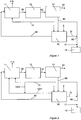
- a stream of natural gas flowing in a charge pipe (1) arriving in the adsorption unit (15) and a stream of water vapor flowing in a pipe (2) of water vapor arriving in the adsorption units (15) are sent indirectly as feedstock to a steam reforming unit (11).
- the heat required for the reaction is produced by a fuel flow arriving via a conduit (10) into the steam reforming unit (11) in the steam reforming furnace.
- the fuel may be natural gas. This reaction produces at the outlet of the furnace (110) a flue gas containing a little carbon dioxide.
- the stream of synthesis gas circulating in a conduit (30) of synthesis gas from the unit of steam reforming (11) at the steam conversion unit (12) obtained by the steam reforming reaction mainly contains hydrogen (H 2 ), carbon monoxide (CO), carbon dioxide (CO 2 ) , as well as water vapor (H 2 O) and a little unreacted methane (CH 4 ), because the reaction is equilibrated and even at a temperature of 900 ° C, there remains about 4% of unreacted methane.
- This synthesis gas stream is sent through the synthesis gas conduit (30) to the steam conversion unit (12). In this unit most of the carbon monoxide is converted to carbon dioxide with the help of water vapor, releasing a little more hydrogen at the same time.
- CO 2 capture unit 13
- MDEA methyldiethylamine
- CO 2 is separated and sent via a conduit (50) of CO 2 to a compression and drying unit, and then transported to a reinjection site such as a depleted deposit or a suitable geological layer.
- the hydrogen-rich gas is discharged through another hydrogen-rich gas conduit (60) connecting the CO 2 capture unit (13) and the adsorption unit (15).
- This gas includes some methane, carbon monoxide and some unconverted carbon dioxide (about 0.5%).
- this hydrogen-rich gas is directed to the activated carbon adsorption unit (15).
- the regeneration is carried out at high pressure by the water vapor supplied. by the conduit (2) of water vapor.
- This steam is then used as a feedstock of the steam reforming unit fed via the steam reforming feed line (90) connecting the adsorption unit (15) and the steam reforming unit (11).
- the impurities CH 4 , CO, CO 2 ) are in this way recycled to the steam reforming reactor.
- a portion of the hydrogen product exiting via the hydrogen line (70) is used in the steam reforming unit (11).
- Part of the hydrogen from the pipe (70) is sent to the burners of the steam reforming unit (to be burned) through the pipe (10) so that the fumes exiting through the pipe (110) do not comprise no CO 2 .
- the remainder of the hydrogen is passed through the conduit (80) to the gas turbine (16) in admixture with the dilution water vapor arriving through the dilution steam pipe (17).
- the CO 2 avoidance rate can be close to 100%.
- the burners of the steam reforming unit (11) are also fed with pure hydrogen at high pressure from the adsorption unit (15).
- This hydrogen is the result of a decompression or depressurization phase carried out in the adsorption unit (15) and described hereinafter.
- This hydrogen supply is via the conduit (1001) of depressurization which starts from the adsorption unit (15) and arrives in the steam reforming unit (11). If necessary the flow of the line (1001) can be supplemented with hydrogen from the conduit (10) via the conduit (1002) which connects the conduit (10) of heat to the conduit (1001) of depressurization.
- the adsorption unit (15) used in the present invention consists of several adsorbers, also called capacities (151 to 156).
- the operating mode is illustrated on the figure 3 in a configuration with 6 adsorbers, configuration not limiting. A different number of capacities is obviously possible without departing from the scope of the present invention and for example 1 to 18, and preferably 5 to 12, but we have limited to 6 to explain the invention more simply.
- This adsorption unit (15) is fed with charge methane, which is required for subsequent purge and pressurization phases, via the charge conduit (1).
- the desorption stage of the impurities present in the hydrogen and adsorbed on the solid is carried out by superheated steam.
- the adsorbent solid must be able to withstand high temperatures, typically between room temperature and 350 ° C, in the presence of superheated steam.
- the adsorbent will be chosen by active carbon adsorbents or carbon molecular sieves.
- activated carbons that have been prepared by physical activation with steam, rather than by chemical activation for example with the acid.
- the activation conditions are indeed more severe than those encountered under the conditions of the invention, especially for the temperature which is generally between 600 and 900 ° C.
- an active carbon containing essentially micropores whose diameter is typically less than 2 nm, and macropores with a diameter greater than 50 nm, and a smallest possible amount of mesopores (diameters between 2 and 50), will be chosen. nm). These diameters can be calculated from nitrogen adsorption isotherms at 77 K according to, for example, the B.J.H. (Mesopore domain), well known to those skilled in the art, and mercury intrusion curves according to Washburn's law (macropore domain), also well known to those skilled in the art.
- the reason for such a choice is explained by the fact that the water vapor present in the adsorbent bed can lead to the phenomenon of capillary condensation in the mesopores of the activated carbon, especially if the temperature of the superheated vapor drops substantially. until reaching the dew point temperature at the considered pressure.
- the relative pressure of the water vapor may give rise to this phenomenon of capillary condensation in the mesopores can be calculated according to the Kelvin equation, using the parameters relating to water. For example, reference may be made to SJ Gregg and KSW Sing (Adsorption, Surface Area and Porosity) and J. Rouquol et al. (Adsorption by Powders and Porous Solids).
- the active carbons used in the context of the invention will be shaped, for example in the form of granules, the diameter of which is for example between 0.5 and 5 mm, of extrudates, the length of which is approximately 0 mm. , 5 to some mm, or crushed a few millimeters of characteristic dimensions.
- microporous volume of activated carbons will for example be between 0.05 and 0.80 cm3 / g, determined for example by nitrogen adsorption at 77 K by the t-plot method, or according to the Dubinin equation and its variants.
- the mesoporous volume will preferably be between 0.05 and 0.30 cm3 / g, determined by adsorption of nitrogen at 77 K at a relative pressure of P / PO close to 0.98-0.99 less than the microporous volume.
- the macroporous volume will preferably be between 0.10 and 0.50 cm3 / g, determined by mercury intrusion.
- active carbons meeting this criterion include, for example, AC35 / 3 active carbon, from Ceca / Arkema, PicaCarb active carbons E460-E and Picactif TA60 or TA90, from Pica Carbon.
- the adsorption cycle in the adsorption unit (15) consists of several phases.
- the six capacities (151 to 156), illustrated on the figure 3 are filled with adsorbent.
- the flow of hydrogen-rich gas to be purified arriving via the conduit (60) is sent into the first capacity (151) at a temperature of between 20 and 100 ° C, preferably between 40 ° C and 80 ° C, and very preferred between 30 ° C and 70 ° C.
- the methane, the CO and the CO 2 contained in this stream are captured on the adsorbent, and the purified hydrogen leaves via the conduit (61).
- the heated hydrogen exits the sixth capacity via the conduit (62) connecting the sixth capacitor (156) and a heat exchanger (21), and is sent to a heat exchanger (21) for further heating by exchange with the dilution water vapor arriving via the dilution water vapor pipe (17).
- the hot hydrogen leaves the heat exchanger (21) through the hot hydrogen conduit (63) connecting the heat exchanger (21) to a fifth capacity (155) at a temperature at least 20 ° C higher. at the condensation temperature of the steam at the operating pressure.
- the hot hydrogen which is fed into the fifth capacity (155) via the conduit (63) makes it possible to evacuate the water vapor remaining in the capacity after the regeneration step.
- This steam is sent in mixture with hydrogen in part to the burners of the steam reforming furnace through the conduit (10) and partly to the gas turbine (16) through the conduit (80).
- part of the hydrogen flowing in the duct (62) can be sampled at the outlet of the sixth capacity (156), cooled by a heat exchanger using cooling water or air, and compressed by a compressor. There is thus a stream of pure hydrogen sent for example to an outdoor unit to external users.
- the remainder of the hydrogen of the conduit (62) is heated by the exchanger (21) before sweeping the fifth capacitor (155), exiting through the conduit (70) connecting the fifth capacitor (155) to the gas turbine ( 16), is then mixed with the dilution water vapor (17), cooled by the exchanger (21), and is sent as fuel to the steam reforming oven (11) via the conduit (10).
- the fourth capacity (154) is swept by water vapor supplied by the steam conduit (2).
- the water vapor charged with methane and CO 2 is evacuated from the fourth capacity (154) via the duct (91) connecting the third capacity (153) to a heat exchanger (20), is slightly cooled in this second exchanger heat exchange (20) by exchange with the natural gas arriving via the pipe (1), then mixed with the natural gas from the third capacity (153), to be then sent via the vapor reforming feed pipe (90) to the steam reforming unit (11).
- the third capacity (153) is first reduced to the pressure of the natural gas which is about 3.5 MPa, and then gradually warmed by sweeping with hot natural gas (250 ° C to 350 ° C) arriving through the duct. (1) after preheating by exchange with water vapor supplied via the conduit (91).
- the invention consists in depressurizing the second capacity (152), during the previous steps, using the conduit (1001) of depressurization.
- the hydrogen flowing in the duct (1001) is then sent to the medium and / or low pressure burners of the furnaces serving to supply the energy required for the steam reforming unit (11).
- This sequence at an intermediate pressure between the adsorption pressure and the burner pressure, it is possible to discharge mainly the hydrogen present in the adsorbent bed.
- some of the other constituents such as methane, ethane, a small amount of CO and water vapor are also extracted and represent less than 10 mol% in this stream.
- the light hydrocarbons come from both the gas trapped between the adsorbent grains in each capacity and the partial desorption of gases such as methane due to a change in the partial pressure.
- the hydrogen circulating in the duct (1001) can also be sent to the medium and / or low pressure burners of the furnaces serving to supply the energy required for the steam reforming unit (11) in a mixture with a part of the flow of hot hydrogen and saturated with water vapor obtained after sweeping the regenerated adsorber and flowing in the conduit (70).
- the figure 4 represents one of the capacities or adsorbers, for example the first (151) containing the adsorbent substance which may be activated carbon.
- the ducts (60, 1, 2, 63 and 61) respectively supplying the hydrogen to be purified, the natural gas, the water vapor, the hot pure hydrogen and the pure cold hydrogen, are connected to the capacity with valves to isolate each circuit.
- the ducts (61, 1001, 90, 91, 70, and 62) respectively discharging cold pure hydrogen, hydrogen from the depressurization step, methane to the steam reforming unit, water vapor to unity steam-reforming, pure hydrogen saturated with water vapor and pure hydrogen, are also connected to the capacity with isolation valves.
- the figure 5 represents the arrangement of six capacities or adsorbers in parallel (151, 152, 153, 154, 155 and 156) allowing continuous operation of the installation. In this case also a different number of capacities is obviously possible without departing from the scope of the present invention, but we have limited our to 6 to be able to explain the invention in more detail simply.
- the first capacity (151) receives cold and impure hydrogen through the conduit (60), retains the various impurities on the adsorbent, and the pure hydrogen comes out through the conduit (61).
- the second capacity (152) is depressurized.
- the third capacity (153) has just been removed from the circuit and is regenerating.
- pressurization with hot methane arriving via line (1) then the adsorbent is heated with methane to a temperature between 250 ° C and 350 ° C where water vapor subsequently used for regeneration is not likely to condense (vapor pressure of water at about 2.5 MPa 225 ° C, at 3.5 MPa, about 245 ° C).
- the methane at the outlet of the adsorbent is sent via the conduit (90) to the steam reforming unit.
- the fourth capacity (154) is in regeneration: the superheated steam is supplied by the conduit (2), it allows to desorb the methane, CO and CO 2 present on the adsorbent.
- the mixture steam, methane and impurities will be returned to the steam reforming unit through the conduit (91), mixed with the methane from the third capacity (153).
- the fifth capacity (155) is purging water vapor through the circulation of pure hot hydrogen brought by the conduit (63), and returned through the conduit (70).
- the sixth capacity (156) is cooled by pure cold hydrogen brought by the conduit (61), the pure hydrogen being returned via the conduit (62).
- the first capacity (151) is depressurized.
- the second capacitor (152) is pressurized and heated, the third capacitor (153) is regenerating, the fourth capacitor (154) is purging, the fifth capacitor (155) is cooling and the sixth capacitor (156) is online about the hydrogen to purify.
- the first capacity (151) goes into pressurization and heating, the second capacity (152) in regeneration, the third capacity (153) is purged, the fourth capacity (154) is cooling the fifth capacity (155) is in hydrogen purification, the sixth capacity (156) is depressurized.
- the first capacity (151) is in regeneration the second capacity (152) purge, the third capacity (153) is in cooling, the fourth capacity (154) is in hydrogen purification the fifth capacity (155) is depressurized and the sixth capacity (156) is pressurized and heated by methane.
- the first capacity (151) is in purge
- the second capacity (152) is in cooling
- the third capacity (153) is in hydrogen purification
- the fourth capacity (154) is in depressurization
- the fifth capacity (155) is pressurizing and heating with methane
- the sixth capacity (156) goes into regeneration by circulation of water vapor.
- the first capacity (151) is in cooling
- the second capacity (152) is in hydrogen purification
- the third capacity (153) is in depressurization
- the fourth capacity (154) is in pressurization and heating by the methane
- the fifth capacity (155) goes into regeneration by circulation of water vapor and the sixth capacity (156) is purged.
- the complete cycle is complete, and the next phase is similar to the first one.
- the method which is the subject of the invention, thus makes it possible to capture the impurities present (CH 4 , CO, CO 2 ) in the stream rich in hydrogen (leaving the amine wash) and to return them under pressure with the steam reforming charge. . It can be summarized as described below.
- the figure 6 details an embodiment of the steam reforming unit (11) using HyGenSys TM (registered trademark) which means "Hydrogen Generation System", that is to say hydrogen production system.
- HyGenSys TM registered trademark
- Hydrogen Generation System that is to say hydrogen production system.
- This is a version of the process of co-production of hydrogen and electricity from natural gas suitable for capturing CO 2 pre-combustion.
- HyGenSys TM is a process that combines a gas turbine and a compact reforming reactor-exchanger with natural gas steam. The specificity of the process is related to how heat is supplied to the very endothermic natural gas reforming reaction.
- the mixture (preheated desulfurized natural gas + vapor) is introduced via the conduit (90) into the reactor-exchanger (206) making it possible to carry out the steam reforming reaction leading to the production of a synthesis gas via the conduit ( 30).
- the heat is supplied by hot gases from a gas turbine cogeneration device.
- the method comprises compressing the air introduced via the conduit (201) into a compression section (202), a first combustion step in a combustion chamber (203) under pressure (for example 1.8 MPa) between compressed air and a mixture rich in hydrogen.
- the hydrogen-rich mixture from the conduit (10) is diluted to 50% by volume, for example with steam (21).
- the mixture is then expanded in an expansion section (204) consisting of a turbine connected to the same shaft as the compressor.
- the expansion of the turbine provides the necessary power to the compressor, the outlet pressure of the turbine is of the order of 0.5 MPa, It is achieved a combustion in the unit (205) of the gas output of the unit (204). ) and mixed with the hydrogen-rich gas from either conduit 10 in the case of figure 3 either of the conduit 1001 with a possible addition of hydrogen-rich gas of the conduit 1002 in the case of the figure 6 .
- the flow rate of hydrogen-rich mixture is adjusted so as to obtain a temperature of the order of 1260 ° C. at the outlet of this combustion chamber.
- the hot fumes obtained provide the necessary heat to the reactor-exchanger (206).
- the fumes cooled at the outlet section (206) are reheated in the combustion chamber (207) by the addition of a rich hydrogen stream from the conduit (1001) with a possible addition of hydrogen-rich gas from conduit (1002) from the conduit (10) ( figure 2 ).
- the hydrogen flowing in the duct (1001) is hydrogen at low or medium pressure, it may be advantageous to have a supplement of hydrogen transmitted via the duct (10) via the duct (1002) to feed some burner ramps.
- the fumes are then sent to an expansion turbine (208) so as to recover the flash energy in the form of electricity via an alternator (209).
- the HyGenSys TM process also facilitates capture of CO 2 for sequestration.
- Examples 1 and 2 are based on use of HyGenSys TM technology.
- Examples 1 and 2 are carried out with the same turbines, which leads to slight variations in the introduced natural gas flow rate and recovered electric power.
- the goal is to produce 485 MW of electricity using a combined cycle (gas turbine + steam heat recovery at turbine outlet with steam generation and steam turbines) using HyGenSys TM technology.
- the total flow rate of pure hydrogen fed to the turbines is 469,190 Nm 3 / h without intermediate purge step.
- the flow of pure hydrogen recycled is 22 430 Nm3 / h
- the heat required for the steam reforming reaction is provided by the combustion fumes in the exchanger reactors.
- the natural gas flow rate is 114,800 Nm 3 / h.
- the steam flow rate for steam reforming is 422 730 Nm 3 / h.
- the dilution steam flow rate is 308,100 Nm 3 / h.
- the adsorption unit consists of 4 parallel adsorption units each having 5 capacities.
- the capture rate of CO 2 is then 98.1%.
- the goal is to produce 490 MW of electricity using a combined cycle (gas turbine + steam heat recovery at turbine outlet with steam generation and steam turbines) using HyGenSys TM technology.
- the total flow rate of pure hydrogen fed to the turbines is 431 690 Nm 3 / h, ie a reduction of 8% (relative to the comparative example) of which 26 760 Nm 3 / h from the intermediate purge step described in FIG. present invention.
- the recycled pure hydrogen flow rate is 9610 Nm3 / h, ie a reduction of 57% (relative to the comparative example).
- the heat required for the steam reforming reaction is provided by the combustion fumes in the exchanger reactors.
- the natural gas flow rate is 113 930 Nm 3 / h (reduction of 0.8% compared with the comparative example).
- the steam flow rate for steam reforming is 400 990 Nm 3 / h.
- the dilution steam flow rate is 302 190 Nm 3 / h.
- the adsorption unit used consists of 4 adsorption units (15) in parallel each having 6 capacities.
- the overall energy efficiency is 41.4%.
- the CO 2 capture rate is 93.5%, this value is greater than the target of 90%.
Landscapes
- Chemical & Material Sciences (AREA)
- Organic Chemistry (AREA)
- Chemical Kinetics & Catalysis (AREA)
- Engineering & Computer Science (AREA)
- Combustion & Propulsion (AREA)
- Inorganic Chemistry (AREA)
- Health & Medical Sciences (AREA)
- General Health & Medical Sciences (AREA)
- Hydrogen, Water And Hydrids (AREA)
- Separation Of Gases By Adsorption (AREA)
Claims (10)
- Verfahren zur Erzeugung von Wasserstoff aus einer Kohlenwasserstoffcharge und Wasserdampf, umfassend:- einen Schritt der Erzeugung eines Synthesegases in einer Einheit zur Dampfreformierung des Kohlenwasserstoffcharge in Gegenwart des Wasserdampfes, wobei ein Brennstoff die für die Reaktion notwendige Wärme liefert,- einen Schritt der Dampfumwandlung des in dem vorhergehenden Schritt erhaltenen Synthesegases, wodurch ein Wasserstoffstrom erzeugt wird, der Methan und Kohlendioxid enthält,- einen Schritt der Abscheidung des in dem im Dampfumwandlungsschritt erhaltenen Stroms enthaltenen Kohlendioxids, der es ermöglicht, das Kohlendioxid vom Wasserstoffstrom zu trennen,- einen Schritt der Abscheidung und Rezyklierung der in dem Wasserstoffstrom enthaltenen Verunreinigungen, der in einer Adsorptionseinheit, umfassend mindestens zwei Adsorber, erfolgt, wobei der Schritt der Abscheidung und Rezyklierung nacheinander mindestens die folgenden Phasen umfasst:- Adsorption der Verunreinigungen am ersten Adsorber,- Dekompression und Regeneration des ersten Adsorbers,- Adsorption der Verunreinigungen am zweiten Adsorber,wobei die Dekompressionsphase bei einem Druck zwischen 0,2 MPa und 1,4 MPa, bei einer Temperatur zwischen 20°C und 100°C und bei einer Geschwindigkeit zwischen 0,05 MPa pro Minute und 2 MPa pro Minute erfolgt, und wobei die Dekompressionsphase einen Wasserstoffstrom erzeugt, der in der Einheit zur Dampfreformierung verbrannt wird.
- Verfahren zur Erzeugung von Wasserstoff nach Anspruch 1, bei dem die Phase der Dekompression und Regeneration des Adsorbers auf folgende Weise durchgeführt wird:- Aus der Linie-Nehmen des ersten Adsorbers und In die Linie-Schaltens des zweiten Adsorbers,- Dekompression des ersten Adsorbers, Rekompression und Spülen des ersten Adsorbers mit einem Strom eines Kohlenwasserstoffcharge, die dazu bestimmt ist, als Charge für die Einheit zur Dampfreformierung zu dienen, und durch Austausch mit Wasserdampf, der ebenfalls für die Einheit zur Dampfreformierung bestimmt ist, auf eine Temperatur um mindestens 20°C über der Kondensationstemperatur de s Wasserdampfes erhitzt wird,- Regeneration des erhitzten Adsorbers und Desorption der Verunreinigungen durch Zirkulation von um mindestens 20°C überhitztem Wasserdampf, der für die Einheit zur Dampfreformierung bestimmt ist,- Beseitigung des in dem regenerierten Adsorber vorhandenen Wasserdampfes durch ein Spülen des Adsorbers mit einem reinen und heißen Wasserstoffstrom, wodurch ein heißer und mit Wasserdampf gesättigter Wasserstoffstrom erzeugt wird,- Spülen des von dem Wasserdampf befreiten Adsorbers mit einem reinen und kalten Wasserstoffstrom.
- Verfahren zur Erzeugung von Wasserstoff nach Anspruch 2, bei dem die Dekompressionsphase einen Wasserstoffstrom erzeugt, der im Gemisch mit einem Teil des heißen und mit Wasserdampf gesättigten Wasserstoffstroms, der nach Spülen des regenerierten Adsorbers erhalten wird, geschickt wird, der in der Einheit zur Dampfreformierung verbrannt wird.
- Verfahren zur Erzeugung von Wasserstoff nach einem der Ansprüche 2 bis 3, bei dem nach der Beseitigung des Wasserdampfes ein Teil des heißen und mit Wasserdampf gesättigten Wasserstoffstroms in der Reformierungseinheit verbrannt wird, und der andere Teil des Wasserstoffstroms im Gemisch mit verdünntem Wasserdampf zu einer Gasturbine zur Stromerzeugung geschickt wird.
- Verfahren zur Erzeugung von Wasserstoff nach einem der Ansprüche 2 bis 3, bei dem nach der Beseitigung des Wasserdampfes ein Teil des nach dem Spülen des regenerierten Adsorbers erhaltenen Wasserstoffstroms zu einer externen Einheit geschickt wird, während der Rest des Wasserstoffs für das Heißspülen verwendet und dann zu den Brennern der Reformierungseinheit geschickt wird.
- Verfahren zur Erzeugung von Wasserstoff nach einem der Ansprüche 2 bis 5, bei dem nach dem Spülen mit kaltem Wasserstoff der erhitzte Wasserstoffstrom, der nach der Abkühlungsphase des Adsorbers erhalten wird, durch Austausch mit Wasserdampf wieder erhitzt und in der Phase der Beseitigung des in dem Adsorber vorhandenen Wasserdampfes verwendet wird.
- Verfahren zur Erzeugung von Wasserstoff nach einem der Ansprüche 1 bis 6, bei dem die Kohlenwasserstoffcharge Erdgas ist.
- Verfahren zur Erzeugung von Wasserstoff nach einem der Ansprüche 1 bis 7, bei dem die adsorbierten Verunreinigungen Methan, Kohlendioxid und Kohlenmonoxid sind.
- Verfahren zur Erzeugung von Wasserstoff nach einem der Ansprüche 1 bis 8, bei dem der Schritt der Erzeugung des Synthesegases bei einem Druck zwischen 2,5 MPa und 3,5 MPa durchgeführt wird.
- Verfahren zur Erzeugung von Wasserstoff nach einem der Ansprüche 1 bis 9, bei dem der Schritt der Abscheidung des Kohlendioxids in einer Amineinheit erfolgt, die Methyldiethylamin und mindestens ein weiteres Amin verwendet.
Applications Claiming Priority (1)
| Application Number | Priority Date | Filing Date | Title |
|---|---|---|---|
| FR1003089A FR2962993B1 (fr) | 2010-07-23 | 2010-07-23 | Procede de production d'hydrogene avec purge a pression intermediaire |
Publications (2)
| Publication Number | Publication Date |
|---|---|
| EP2409950A1 EP2409950A1 (de) | 2012-01-25 |
| EP2409950B1 true EP2409950B1 (de) | 2017-07-12 |
Family
ID=43242160
Family Applications (1)
| Application Number | Title | Priority Date | Filing Date |
|---|---|---|---|
| EP11290245.7A Not-in-force EP2409950B1 (de) | 2010-07-23 | 2011-05-27 | Verfahren zur Erzeugung von Wasserstoff mit Zwischendruckspülung |
Country Status (5)
| Country | Link |
|---|---|
| US (1) | US8784516B2 (de) |
| EP (1) | EP2409950B1 (de) |
| JP (1) | JP5840884B2 (de) |
| CA (1) | CA2746904C (de) |
| FR (1) | FR2962993B1 (de) |
Families Citing this family (5)
| Publication number | Priority date | Publication date | Assignee | Title |
|---|---|---|---|---|
| JP5718272B2 (ja) * | 2012-04-27 | 2015-05-13 | 株式会社 伊藤園 | 茶飲料の製造方法 |
| CA2966458C (en) | 2012-12-19 | 2018-05-29 | Keith Warren | Method of retrofitting a building |
| WO2017195817A1 (ja) * | 2016-05-12 | 2017-11-16 | 積水化学工業株式会社 | 炭化水素の改質方法、有機酸素化物の製造方法、及び有機酸素化物の製造システム |
| US12269741B2 (en) * | 2021-09-06 | 2025-04-08 | Bong Ju Lee | Reforming system and method |
| US12606759B2 (en) | 2022-05-05 | 2026-04-21 | Sagebrush Pipeline Equipment Co., Llc | System and method for blending hydrogen gas |
Family Cites Families (17)
| Publication number | Priority date | Publication date | Assignee | Title |
|---|---|---|---|---|
| US4475929A (en) * | 1978-12-05 | 1984-10-09 | Union Carbide Corporation | Selective adsorption process |
| EP0243350A1 (de) * | 1985-10-21 | 1987-11-04 | Union Carbide Corporation | Wasserstoffgewinnung aus gasströmen |
| US4693730A (en) * | 1986-07-24 | 1987-09-15 | Union Carbide Corporation | Pressure swing adsorption product purity control method and apparatus |
| US5203888A (en) * | 1990-11-23 | 1993-04-20 | Uop | Pressure swing adsorption process with multiple desorption steps |
| US5753010A (en) * | 1996-10-28 | 1998-05-19 | Air Products And Chemicals, Inc. | Hydrogen recovery by pressure swing adsorption integrated with adsorbent membranes |
| US6103143A (en) * | 1999-01-05 | 2000-08-15 | Air Products And Chemicals, Inc. | Process and apparatus for the production of hydrogen by steam reforming of hydrocarbon |
| JP3856987B2 (ja) * | 1999-06-21 | 2006-12-13 | 東京瓦斯株式会社 | 水素精製用3塔式psa装置におけるオフガスタンクからのオフガス圧力の制御方法 |
| US6521143B1 (en) | 2000-04-13 | 2003-02-18 | Air Products And Chemicals, Inc. | Co-production of carbon monoxide-rich syngas wth high purity hydrogen |
| JP3891773B2 (ja) * | 2000-10-20 | 2007-03-14 | 大陽日酸株式会社 | ガスの分離精製方法及びその装置 |
| AU2002217475B2 (en) * | 2000-12-25 | 2005-02-17 | Sumitomo Seika Chemicals Co., Ltd. | Method for separating hydrogen gas |
| US6706770B2 (en) * | 2002-04-04 | 2004-03-16 | Air Products And Chemicals, Inc. | Co-production of hydrogen and methanol from steam reformate |
| FR2852358B1 (fr) | 2003-03-13 | 2006-06-09 | Procede et un dispositif de cogeneration par turbine a gaz avec chambre de postcombustion | |
| US7752848B2 (en) | 2004-03-29 | 2010-07-13 | General Electric Company | System and method for co-production of hydrogen and electrical energy |
| US7988948B2 (en) * | 2008-03-17 | 2011-08-02 | Air Products And Chemicals, Inc. | Steam-hydrocarbon reforming method with limited steam export |
| US20100037521A1 (en) * | 2008-08-13 | 2010-02-18 | L'Air Liquide Societe Anonyme Pour L'Etude et l'Exploitatation Des Procedes Georges Claude | Novel Steam Reformer Based Hydrogen Plant Scheme for Enhanced Carbon Dioxide Recovery |
| FR2936507B1 (fr) | 2008-09-29 | 2011-04-08 | Inst Francais Du Petrole | Procede de production d'hydrogene avec captation totale du co2 et recyclage du methane non converti |
| US20100196259A1 (en) * | 2009-02-05 | 2010-08-05 | Air Products And Chemicals, Inc. | CO2-Sorptive Pellets and Uses Thereof |
-
2010
- 2010-07-23 FR FR1003089A patent/FR2962993B1/fr active Active
-
2011
- 2011-05-27 EP EP11290245.7A patent/EP2409950B1/de not_active Not-in-force
- 2011-07-19 CA CA2746904A patent/CA2746904C/fr not_active Expired - Fee Related
- 2011-07-21 US US13/187,844 patent/US8784516B2/en not_active Expired - Fee Related
- 2011-07-25 JP JP2011161738A patent/JP5840884B2/ja not_active Expired - Fee Related
Also Published As
| Publication number | Publication date |
|---|---|
| CA2746904A1 (fr) | 2012-01-23 |
| US20120017511A1 (en) | 2012-01-26 |
| FR2962993B1 (fr) | 2013-11-01 |
| US8784516B2 (en) | 2014-07-22 |
| JP5840884B2 (ja) | 2016-01-06 |
| JP2012025655A (ja) | 2012-02-09 |
| EP2409950A1 (de) | 2012-01-25 |
| CA2746904C (fr) | 2016-08-30 |
| FR2962993A1 (fr) | 2012-01-27 |
Similar Documents
| Publication | Publication Date | Title |
|---|---|---|
| EP2168913B1 (de) | Herstellungsverfahren von wasserstoff mit vollständiger aufnahme von co2 und recycling des nicht umgewandelten methans | |
| US8268044B2 (en) | Separation of a sour syngas stream | |
| EP2376373A1 (de) | Herstellung von wasserstoff aus einem reformiergas und gleichzeitiges abfangen von co2-coprodukt | |
| CA2746904C (fr) | Procede de production d'hydrogene avec purge a pression intermediaire | |
| EP3142967B1 (de) | Behandlungsverfahren zur abscheidung von kohlendioxid und wasserstoff aus einer mischung | |
| JP2010083754A5 (de) | ||
| FR3097450A1 (fr) | Traitement d’un flux de méthane comprenant des COV et du dioxyde de carbone par combinaison d’une unité d’adsorption et d’une unité de séparation par membrane | |
| WO2008093012A2 (fr) | Procede de production d'un gaz de synthese purifie a partir de biomasse incluant une etape de purification en amont de l'oxydation partielle | |
| CA2971959A1 (fr) | Procede de vaporeformage de gaz naturel presentant deux chambres de combustion generant les fumees chaudes apportant les calories necessaires au procede et connectees en serie ou en parallele | |
| WO2010076463A1 (fr) | Procede de capture du dioxyde de carbone par cryo-condensation | |
| EP2709745A1 (de) | Verfahren zur reinigung durch adsorption mit regeneration anhand eines gases mit einer unerwünschten komponente im gereinigten gas | |
| JP2025506787A (ja) | 炭素捕獲を用いた改質 | |
| FR2836058A1 (fr) | Procede de separation d'un melange gazeux et installation de mise en oeuvre d'un tel procede | |
| EP4062998A1 (de) | Anlage und verfahren zur gewinnung von biomethan, das die anforderungen eines transportnetzes erfüllt | |
| FR2941937A1 (fr) | Procede de production d'hydrogene avec captation totale du co2, et reduction du methane non converti | |
| CN120265571A (zh) | 用于碳中和发电的方法和系统 | |
| FR3120232A3 (fr) | Procédé d’ultra-purification d’une fraction de l’hydrogène issu d’un PSA H2 | |
| FR2889971A1 (fr) | Prcede de valorisation du gaz de depressurisation d'une unite vpsa co2 |
Legal Events
| Date | Code | Title | Description |
|---|---|---|---|
| AK | Designated contracting states |
Kind code of ref document: A1 Designated state(s): AL AT BE BG CH CY CZ DE DK EE ES FI FR GB GR HR HU IE IS IT LI LT LU LV MC MK MT NL NO PL PT RO RS SE SI SK SM TR |
|
| AX | Request for extension of the european patent |
Extension state: BA ME |
|
| PUAI | Public reference made under article 153(3) epc to a published international application that has entered the european phase |
Free format text: ORIGINAL CODE: 0009012 |
|
| 17P | Request for examination filed |
Effective date: 20120725 |
|
| GRAP | Despatch of communication of intention to grant a patent |
Free format text: ORIGINAL CODE: EPIDOSNIGR1 |
|
| INTG | Intention to grant announced |
Effective date: 20170120 |
|
| GRAS | Grant fee paid |
Free format text: ORIGINAL CODE: EPIDOSNIGR3 |
|
| GRAA | (expected) grant |
Free format text: ORIGINAL CODE: 0009210 |
|
| AK | Designated contracting states |
Kind code of ref document: B1 Designated state(s): AL AT BE BG CH CY CZ DE DK EE ES FI FR GB GR HR HU IE IS IT LI LT LU LV MC MK MT NL NO PL PT RO RS SE SI SK SM TR |
|
| REG | Reference to a national code |
Ref country code: GB Ref legal event code: FG4D Free format text: NOT ENGLISH |
|
| REG | Reference to a national code |
Ref country code: CH Ref legal event code: EP |
|
| REG | Reference to a national code |
Ref country code: AT Ref legal event code: REF Ref document number: 908134 Country of ref document: AT Kind code of ref document: T Effective date: 20170715 |
|
| REG | Reference to a national code |
Ref country code: IE Ref legal event code: FG4D Free format text: LANGUAGE OF EP DOCUMENT: FRENCH |
|
| REG | Reference to a national code |
Ref country code: DE Ref legal event code: R096 Ref document number: 602011039451 Country of ref document: DE |
|
| RAP2 | Party data changed (patent owner data changed or rights of a patent transferred) |
Owner name: IFP ENERGIES NOUVELLES |
|
| REG | Reference to a national code |
Ref country code: NL Ref legal event code: MP Effective date: 20170712 |
|
| REG | Reference to a national code |
Ref country code: LT Ref legal event code: MG4D |
|
| REG | Reference to a national code |
Ref country code: AT Ref legal event code: MK05 Ref document number: 908134 Country of ref document: AT Kind code of ref document: T Effective date: 20170712 |
|
| PG25 | Lapsed in a contracting state [announced via postgrant information from national office to epo] |
Ref country code: FI Free format text: LAPSE BECAUSE OF FAILURE TO SUBMIT A TRANSLATION OF THE DESCRIPTION OR TO PAY THE FEE WITHIN THE PRESCRIBED TIME-LIMIT Effective date: 20170712 Ref country code: SE Free format text: LAPSE BECAUSE OF FAILURE TO SUBMIT A TRANSLATION OF THE DESCRIPTION OR TO PAY THE FEE WITHIN THE PRESCRIBED TIME-LIMIT Effective date: 20170712 Ref country code: HR Free format text: LAPSE BECAUSE OF FAILURE TO SUBMIT A TRANSLATION OF THE DESCRIPTION OR TO PAY THE FEE WITHIN THE PRESCRIBED TIME-LIMIT Effective date: 20170712 Ref country code: NO Free format text: LAPSE BECAUSE OF FAILURE TO SUBMIT A TRANSLATION OF THE DESCRIPTION OR TO PAY THE FEE WITHIN THE PRESCRIBED TIME-LIMIT Effective date: 20171012 Ref country code: NL Free format text: LAPSE BECAUSE OF FAILURE TO SUBMIT A TRANSLATION OF THE DESCRIPTION OR TO PAY THE FEE WITHIN THE PRESCRIBED TIME-LIMIT Effective date: 20170712 Ref country code: AT Free format text: LAPSE BECAUSE OF FAILURE TO SUBMIT A TRANSLATION OF THE DESCRIPTION OR TO PAY THE FEE WITHIN THE PRESCRIBED TIME-LIMIT Effective date: 20170712 Ref country code: LT Free format text: LAPSE BECAUSE OF FAILURE TO SUBMIT A TRANSLATION OF THE DESCRIPTION OR TO PAY THE FEE WITHIN THE PRESCRIBED TIME-LIMIT Effective date: 20170712 |
|
| PG25 | Lapsed in a contracting state [announced via postgrant information from national office to epo] |
Ref country code: LV Free format text: LAPSE BECAUSE OF FAILURE TO SUBMIT A TRANSLATION OF THE DESCRIPTION OR TO PAY THE FEE WITHIN THE PRESCRIBED TIME-LIMIT Effective date: 20170712 Ref country code: RS Free format text: LAPSE BECAUSE OF FAILURE TO SUBMIT A TRANSLATION OF THE DESCRIPTION OR TO PAY THE FEE WITHIN THE PRESCRIBED TIME-LIMIT Effective date: 20170712 Ref country code: GR Free format text: LAPSE BECAUSE OF FAILURE TO SUBMIT A TRANSLATION OF THE DESCRIPTION OR TO PAY THE FEE WITHIN THE PRESCRIBED TIME-LIMIT Effective date: 20171013 Ref country code: PL Free format text: LAPSE BECAUSE OF FAILURE TO SUBMIT A TRANSLATION OF THE DESCRIPTION OR TO PAY THE FEE WITHIN THE PRESCRIBED TIME-LIMIT Effective date: 20170712 Ref country code: IS Free format text: LAPSE BECAUSE OF FAILURE TO SUBMIT A TRANSLATION OF THE DESCRIPTION OR TO PAY THE FEE WITHIN THE PRESCRIBED TIME-LIMIT Effective date: 20171112 Ref country code: ES Free format text: LAPSE BECAUSE OF FAILURE TO SUBMIT A TRANSLATION OF THE DESCRIPTION OR TO PAY THE FEE WITHIN THE PRESCRIBED TIME-LIMIT Effective date: 20170712 Ref country code: BG Free format text: LAPSE BECAUSE OF FAILURE TO SUBMIT A TRANSLATION OF THE DESCRIPTION OR TO PAY THE FEE WITHIN THE PRESCRIBED TIME-LIMIT Effective date: 20171012 |
|
| REG | Reference to a national code |
Ref country code: DE Ref legal event code: R097 Ref document number: 602011039451 Country of ref document: DE |
|
| PG25 | Lapsed in a contracting state [announced via postgrant information from national office to epo] |
Ref country code: DK Free format text: LAPSE BECAUSE OF FAILURE TO SUBMIT A TRANSLATION OF THE DESCRIPTION OR TO PAY THE FEE WITHIN THE PRESCRIBED TIME-LIMIT Effective date: 20170712 Ref country code: RO Free format text: LAPSE BECAUSE OF FAILURE TO SUBMIT A TRANSLATION OF THE DESCRIPTION OR TO PAY THE FEE WITHIN THE PRESCRIBED TIME-LIMIT Effective date: 20170712 Ref country code: CZ Free format text: LAPSE BECAUSE OF FAILURE TO SUBMIT A TRANSLATION OF THE DESCRIPTION OR TO PAY THE FEE WITHIN THE PRESCRIBED TIME-LIMIT Effective date: 20170712 |
|
| PLBE | No opposition filed within time limit |
Free format text: ORIGINAL CODE: 0009261 |
|
| STAA | Information on the status of an ep patent application or granted ep patent |
Free format text: STATUS: NO OPPOSITION FILED WITHIN TIME LIMIT |
|
| PG25 | Lapsed in a contracting state [announced via postgrant information from national office to epo] |
Ref country code: EE Free format text: LAPSE BECAUSE OF FAILURE TO SUBMIT A TRANSLATION OF THE DESCRIPTION OR TO PAY THE FEE WITHIN THE PRESCRIBED TIME-LIMIT Effective date: 20170712 Ref country code: SK Free format text: LAPSE BECAUSE OF FAILURE TO SUBMIT A TRANSLATION OF THE DESCRIPTION OR TO PAY THE FEE WITHIN THE PRESCRIBED TIME-LIMIT Effective date: 20170712 Ref country code: IT Free format text: LAPSE BECAUSE OF FAILURE TO SUBMIT A TRANSLATION OF THE DESCRIPTION OR TO PAY THE FEE WITHIN THE PRESCRIBED TIME-LIMIT Effective date: 20170712 Ref country code: SM Free format text: LAPSE BECAUSE OF FAILURE TO SUBMIT A TRANSLATION OF THE DESCRIPTION OR TO PAY THE FEE WITHIN THE PRESCRIBED TIME-LIMIT Effective date: 20170712 |
|
| 26N | No opposition filed |
Effective date: 20180413 |
|
| PG25 | Lapsed in a contracting state [announced via postgrant information from national office to epo] |
Ref country code: SI Free format text: LAPSE BECAUSE OF FAILURE TO SUBMIT A TRANSLATION OF THE DESCRIPTION OR TO PAY THE FEE WITHIN THE PRESCRIBED TIME-LIMIT Effective date: 20170712 |
|
| PG25 | Lapsed in a contracting state [announced via postgrant information from national office to epo] |
Ref country code: MT Free format text: LAPSE BECAUSE OF FAILURE TO SUBMIT A TRANSLATION OF THE DESCRIPTION OR TO PAY THE FEE WITHIN THE PRESCRIBED TIME-LIMIT Effective date: 20170712 |
|
| REG | Reference to a national code |
Ref country code: DE Ref legal event code: R119 Ref document number: 602011039451 Country of ref document: DE |
|
| REG | Reference to a national code |
Ref country code: CH Ref legal event code: PL |
|
| GBPC | Gb: european patent ceased through non-payment of renewal fee |
Effective date: 20180527 |
|
| REG | Reference to a national code |
Ref country code: BE Ref legal event code: MM Effective date: 20180531 |
|
| PG25 | Lapsed in a contracting state [announced via postgrant information from national office to epo] |
Ref country code: MC Free format text: LAPSE BECAUSE OF FAILURE TO SUBMIT A TRANSLATION OF THE DESCRIPTION OR TO PAY THE FEE WITHIN THE PRESCRIBED TIME-LIMIT Effective date: 20170712 |
|
| REG | Reference to a national code |
Ref country code: IE Ref legal event code: MM4A |
|
| PG25 | Lapsed in a contracting state [announced via postgrant information from national office to epo] |
Ref country code: LI Free format text: LAPSE BECAUSE OF NON-PAYMENT OF DUE FEES Effective date: 20180531 Ref country code: CH Free format text: LAPSE BECAUSE OF NON-PAYMENT OF DUE FEES Effective date: 20180531 |
|
| PG25 | Lapsed in a contracting state [announced via postgrant information from national office to epo] |
Ref country code: LU Free format text: LAPSE BECAUSE OF NON-PAYMENT OF DUE FEES Effective date: 20180527 |
|
| PG25 | Lapsed in a contracting state [announced via postgrant information from national office to epo] |
Ref country code: IE Free format text: LAPSE BECAUSE OF NON-PAYMENT OF DUE FEES Effective date: 20180527 Ref country code: DE Free format text: LAPSE BECAUSE OF NON-PAYMENT OF DUE FEES Effective date: 20181201 Ref country code: FR Free format text: LAPSE BECAUSE OF NON-PAYMENT OF DUE FEES Effective date: 20180531 Ref country code: GB Free format text: LAPSE BECAUSE OF NON-PAYMENT OF DUE FEES Effective date: 20180527 |
|
| PG25 | Lapsed in a contracting state [announced via postgrant information from national office to epo] |
Ref country code: BE Free format text: LAPSE BECAUSE OF NON-PAYMENT OF DUE FEES Effective date: 20180531 |
|
| PG25 | Lapsed in a contracting state [announced via postgrant information from national office to epo] |
Ref country code: TR Free format text: LAPSE BECAUSE OF FAILURE TO SUBMIT A TRANSLATION OF THE DESCRIPTION OR TO PAY THE FEE WITHIN THE PRESCRIBED TIME-LIMIT Effective date: 20170712 |
|
| PG25 | Lapsed in a contracting state [announced via postgrant information from national office to epo] |
Ref country code: PT Free format text: LAPSE BECAUSE OF FAILURE TO SUBMIT A TRANSLATION OF THE DESCRIPTION OR TO PAY THE FEE WITHIN THE PRESCRIBED TIME-LIMIT Effective date: 20170712 Ref country code: HU Free format text: LAPSE BECAUSE OF FAILURE TO SUBMIT A TRANSLATION OF THE DESCRIPTION OR TO PAY THE FEE WITHIN THE PRESCRIBED TIME-LIMIT; INVALID AB INITIO Effective date: 20110527 |
|
| PG25 | Lapsed in a contracting state [announced via postgrant information from national office to epo] |
Ref country code: MK Free format text: LAPSE BECAUSE OF NON-PAYMENT OF DUE FEES Effective date: 20170712 Ref country code: CY Free format text: LAPSE BECAUSE OF FAILURE TO SUBMIT A TRANSLATION OF THE DESCRIPTION OR TO PAY THE FEE WITHIN THE PRESCRIBED TIME-LIMIT Effective date: 20170712 |
|
| PG25 | Lapsed in a contracting state [announced via postgrant information from national office to epo] |
Ref country code: AL Free format text: LAPSE BECAUSE OF FAILURE TO SUBMIT A TRANSLATION OF THE DESCRIPTION OR TO PAY THE FEE WITHIN THE PRESCRIBED TIME-LIMIT Effective date: 20170712 |