EP2409938A2 - Underpressure conveyor facility - Google Patents
Underpressure conveyor facility Download PDFInfo
- Publication number
- EP2409938A2 EP2409938A2 EP11174435A EP11174435A EP2409938A2 EP 2409938 A2 EP2409938 A2 EP 2409938A2 EP 11174435 A EP11174435 A EP 11174435A EP 11174435 A EP11174435 A EP 11174435A EP 2409938 A2 EP2409938 A2 EP 2409938A2
- Authority
- EP
- European Patent Office
- Prior art keywords
- vacuum unit
- products
- suction
- suction opening
- transport
- Prior art date
- Legal status (The legal status is an assumption and is not a legal conclusion. Google has not performed a legal analysis and makes no representation as to the accuracy of the status listed.)
- Withdrawn
Links
Images


Classifications
-
- B—PERFORMING OPERATIONS; TRANSPORTING
- B65—CONVEYING; PACKING; STORING; HANDLING THIN OR FILAMENTARY MATERIAL
- B65H—HANDLING THIN OR FILAMENTARY MATERIAL, e.g. SHEETS, WEBS, CABLES
- B65H31/00—Pile receivers
- B65H31/30—Arrangements for removing completed piles
-
- B—PERFORMING OPERATIONS; TRANSPORTING
- B65—CONVEYING; PACKING; STORING; HANDLING THIN OR FILAMENTARY MATERIAL
- B65G—TRANSPORT OR STORAGE DEVICES, e.g. CONVEYORS FOR LOADING OR TIPPING, SHOP CONVEYOR SYSTEMS OR PNEUMATIC TUBE CONVEYORS
- B65G21/00—Supporting or protective framework or housings for endless load-carriers or traction elements of belt or chain conveyors
- B65G21/20—Means incorporated in, or attached to, framework or housings for guiding load-carriers, traction elements or loads supported on moving surfaces
- B65G21/2027—Suction retaining means
- B65G21/2036—Suction retaining means for retaining the load on the load-carrying surface
-
- B—PERFORMING OPERATIONS; TRANSPORTING
- B65—CONVEYING; PACKING; STORING; HANDLING THIN OR FILAMENTARY MATERIAL
- B65H—HANDLING THIN OR FILAMENTARY MATERIAL, e.g. SHEETS, WEBS, CABLES
- B65H2301/00—Handling processes for sheets or webs
- B65H2301/30—Orientation, displacement, position of the handled material
- B65H2301/32—Orientation of handled material
- B65H2301/323—Hanging
-
- B—PERFORMING OPERATIONS; TRANSPORTING
- B65—CONVEYING; PACKING; STORING; HANDLING THIN OR FILAMENTARY MATERIAL
- B65H—HANDLING THIN OR FILAMENTARY MATERIAL, e.g. SHEETS, WEBS, CABLES
- B65H2301/00—Handling processes for sheets or webs
- B65H2301/40—Type of handling process
- B65H2301/42—Piling, depiling, handling piles
- B65H2301/422—Handling piles, sets or stacks of articles
- B65H2301/4225—Handling piles, sets or stacks of articles in or on special supports
- B65H2301/42254—Boxes; Cassettes; Containers
- B65H2301/422548—Boxes; Cassettes; Containers filling or loading process
-
- B—PERFORMING OPERATIONS; TRANSPORTING
- B65—CONVEYING; PACKING; STORING; HANDLING THIN OR FILAMENTARY MATERIAL
- B65H—HANDLING THIN OR FILAMENTARY MATERIAL, e.g. SHEETS, WEBS, CABLES
- B65H2406/00—Means using fluid
- B65H2406/30—Suction means
- B65H2406/32—Suction belts
- B65H2406/323—Overhead suction belt, i.e. holding material against gravity
-
- B—PERFORMING OPERATIONS; TRANSPORTING
- B65—CONVEYING; PACKING; STORING; HANDLING THIN OR FILAMENTARY MATERIAL
- B65H—HANDLING THIN OR FILAMENTARY MATERIAL, e.g. SHEETS, WEBS, CABLES
- B65H2406/00—Means using fluid
- B65H2406/30—Suction means
- B65H2406/35—Other elements with suction surface, e.g. plate or wall
- B65H2406/352—Other elements with suction surface, e.g. plate or wall facing the edge of the handled material
-
- B—PERFORMING OPERATIONS; TRANSPORTING
- B65—CONVEYING; PACKING; STORING; HANDLING THIN OR FILAMENTARY MATERIAL
- B65H—HANDLING THIN OR FILAMENTARY MATERIAL, e.g. SHEETS, WEBS, CABLES
- B65H2701/00—Handled material; Storage means
- B65H2701/10—Handled articles or webs
- B65H2701/19—Specific article or web
- B65H2701/1916—Envelopes and articles of mail
Definitions
- the present invention relates to a device for transporting flat products which have an edge over at least a portion.
- this stream is to be subdivided into individual units and these units are transferred, for example, into a container or the like.
- envelopes In the case of envelopes, these are still sorted by hand from a continuous stream on the basis of certain data, such as postal code areas, and transferred to corresponding transport containers.
- this box is produced as a punching sheet, glued over a longitudinal edge and further transported as even more or less two-dimensional sheet product to the filler. There, the sheet product is then placed in a three-dimensional body, filled by a toothpaste tube is inserted, and the container is closed at the top and bottom.
- Such prefabricated cartons are delivered, for example, in batch sizes of about 250 packages as a horizontally extending stack.
- the operator grasps such a stack, which may well be up to one meter in length and weighs several kilograms, places the hands on both lateral ends, compresses the stack a bit, lifts it off the conveyor, and delivers that stack into a container.
- a vacuum unit which has a longitudinal suction opening on a bottom through which air can be sucked via a vacuum source, wherein a series of planar products to be transported by means of a suction effect generated by negative pressure on one edge can be attached to the underside, and wherein the edge during transport bears against the longitudinally extending suction opening and is aligned transversely thereto.
- the vacuum unit with the attached sheet-like products is movable for this purpose.
- This measure has the advantage that now the assembly of the vacuum unit and the adhering flat products can be moved, for example, from a conveyor belt, from which the series is delivered to flat products, to a container for further transport.
- the vacuum unit is connected to a transport unit, by means of which the vacuum unit can be transferred at least between a first and a second position.
- the transport unit is adapted to the circumstances, which may for example be a pivotable transfer arm, which only implements the vacuum unit, the transport unit can then be a completely movable unit that spends the sheet products to any remote location.
- an effective intake cross section of the intake opening is variable.
- a first advantage is that a change in the effective suction opening makes it possible to adapt to differently long rows of aligned flat products.
- modification of the effective intake opening means that the intake cross section of the intake opening can be sucked in via the air, in particular being variable in its longitudinal extent.
- 250 lined envelopes can have a different length than, for example, 250 contiguous packages provided with a relatively thick folded edge or the like.
- Another advantage is that it can be adapted to a shrinkage of the original row length for a given sheet product, if existing air was sucked between the individual sheet products.
- the device further comprises a sliding cover, can be covered by the areas of the suction port.
- This sliding cover can not only be used to ensure a sizing of the suction, you can break the adhesive contact between the suction and the attached products in the short term by introducing the cover so that they then fall down. Only areas can be covered or the complete intake opening.
- the vacuum unit is designed as a suction strip on which at one end a suction port is present and from the other end of the sliding cover can be introduced.
- This measure has the advantage that by mechanically very simple means both the length adjustment of the suction port is possible and a detachment of the products. But this sliding cover shows yet another advantage, you can, for example, first push the cover very far into the squeegee, so that the suction port is almost completely closed or only slightly open. If you want to attach the flat products gradually to the vacuum unit, then you can then move the cover gradually and thereby make the intake longer and longer, so that gradually more and more products can be attached.
- the vacuum unit on a Teleskopsaugruc, through which the length of the suction opening is variable at the bottom.
- the change in length can be regulated by a drive.
- This measure has the advantage that this drive can be performed fully automatically.
- the drive is regulated, for example, so that it first releases such a length range of the suction opening, as is necessary for the stack. If a stack of a certain length delivered, this is entered, so that the drive then first releases the suction port in this length. As mentioned above, the stack shrinks more or less by applying the negative pressure, so that then the length can be readjusted by an appropriate control.
- a perforated conveyor belt is arranged on the suction opening, which is movable in a transport direction along the longitudinal extension of the suction opening, so that the sheet-like products are transported over the top edge of the perforated conveyor belt hanging.
- This measure has the advantage that in this embodiment not only the flat products can be attached to the suction opening via their edge, but by interposing a perforated conveyor belt, they can also be transported along the longitudinal extension of the suction opening.
- the suction opening has a plurality of slot openings along which runs the perforation of the conveyor belt.
- the perforation of the conveyor belt is formed by holes which extend as rows of holes in both the longitudinal and transverse direction of the suction opening and communicate with the slot openings.
- the device further comprises at least one movable slide, through which the flat products hanging on the vacuum unit can be pushed away.
- This measure has the advantage that the planar products can be moved away from the suction opening somewhat by the slide, so that the adhesive state is interrupted. As a result, the adhering products detach from the suction port or from the transport belt and can be delivered down into a container due to gravity.
- the slider can then be designed so that it accompanies or directs this Ablenseweg, so that the falling down products can be delivered purposefully into a container.
- the slide can be brought into engagement with laterally over the vacuum unit projecting upper edges of the sheet-like products and pushes them downwards from the suction opening.
- This is a particularly economical and mechanically simple embodiment for detaching the products attached to the intake opening from the vacuum unit.
- the vacuum unit has a breaker, via which a vacuum applied to the suction opening can be interrupted at least for a short time.
- This measure has the advantage that the detachment process described above is controlled by interrupting the intake, so that then this detachment process is triggered.
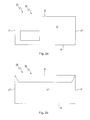
- FIG. 1 to 10 illustrated first embodiment of a device according to the invention is designated in its entirety by the reference numeral 10.
- the device 10 a vacuum unit 12.
- the vacuum unit 12 is formed in cross-section as an approximately U-shaped box 26, the underside 13 is provided with a suction port 14. At the upper end, a port 16 is provided, which connects the vacuum unit with a vacuum source 17, not shown here.
- the vacuum unit 12 further comprises a perforated conveyor belt 18, which is guided in the longitudinal direction of the suction opening 14 in a transport direction 20.
- the transport belt 18 thereby runs over rollers 22 and 24, by means of which the transport belt 18 is moved along the underside 13 of the vacuum unit 12.
- the transport belt 18 is formed as an endless transport belt.
- the device 10 serves for laminar products 28, which have a defined edge 32 at least over a certain section, to be suspended from the transport belt 18 by a negative pressure and to be transported by the latter in the transport direction 20.
- FIG Fig. 2a and 2b a letter envelope shown. This has a front 33, a back 33 ', and two side edges 37 and 37'.
- an upper edge 32 and a lower edge 35 are provided, which, viewed as a whole, surround the approximately rectangular envelope 30.
- a section of the upper edge 32 runs in a straight line, so that this envelope 30 in the in Fig. 1 and 1a shown position on this upper edge 32 adhered to the conveyor belt 18 and can be transported by this.
- the arrangement of the sheet-like products on the underside 13 of the vacuum unit according to the invention is realized so that a corresponding negative pressure is applied to the suction port 14.
- This negative pressure ensures a Sog bin.
- This suction effect has the consequence that a volume flow of air enters the intake opening 14.
- the closer design of the vacuum unit 12 in the region of the intake opening 14 is shown.
- the diaphragm element 36 has a first aperture 38 as shown in FIG Fig. 3a and 3b is shown.
- the first panel is constructed from a rectangular base body 42, which has a plurality of extending slot openings 44 and 44 'extending in the transport direction 20.
- this length of the sides corresponds to the width of the intake opening 14.
- the main body 42 is relatively thick built, for reasons of weight of a lightweight material, such as wood.
- a second panel 40 can be seen, which is substantially thinner and made of a material having a smooth surface, such as a mirror-polished stainless steel or a corresponding plastic material.
- the second panel 40 has slot openings 50 and 50 ', which are congruent with the slot openings 44 and 44' are formed. For reasons of stability, webs 58, 58 'have stopped.
- the opposite short ends 52 and 54 have the same width as the ends 46 and 48 of the first panel 38, so that the second panel 40 can be suitably placed on the first panel 38, as in the Fig. 5a and 5b is shown.
- the second panel 40 is located on the lower side of the first panel 38, ie over this second panel 40 then runs the transport belt 18. As in Fig. 5a can be seen, thus through the entire body of the diaphragm member 36 continuous suction channels 61 are formed.
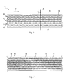
- Fig. 6 is a plan view of the conveyor belt 18 can be seen.
- the transport belt 18 has two opposite edges 62 and 64, which run parallel to the transport direction 20.
- the transport belt 18 has holes 66 as a perforation. These circular holes 66 are arranged in rows 68, wherein the five rows 68 are arranged so that they run along the channels 61 formed by the slot openings of the first and second aperture.
- Each row 68 is composed of two sub-rows 70, which are set to gap, ie the openings of a sub-row 70 are each in gaps between the openings of the adjacent sub-row 70.
- FIG. 6 represented a flat product 28 arranged with its straight edge 32 transversely to the Tarnsportcardi 20 extending or appended before, it can be seen that this upper edge 32 is in registry with a plurality of openings 66 of the perforation, which is exercised over the perforation of the Sog bin, that is the air between the upper edge 32 and the opening 66 is permanently sucked off.
- Fig. 7 It is shown how the rows 68 of the holes 66 of the conveyor belt 18 can run over the longitudinal channels 61 of the diaphragm element 36 in the transport direction. Thereby it is possible, as in Fig. 1 and 1a shown, hanging on the underside surface product 28 to move in the transport direction 20.
- the vacuum unit 12 further comprises a slider 76. This one is like that in Fig. 8 can be seen, movable in the vertical direction 78, where he, as that particular from Fig. 8a and 9th it can be seen, with the upper edge 32 of the products 28 can come into contact, especially in the section in which they look laterally beyond the vacuum unit 12.
- the slider 76 has two slide pairs 80 which can be applied on both sides of the vacuum unit 12 to the top of the block 69 and solve this from the adhesive contact with the conveyor belt 18 and the vacuum unit 12.
- Fig. 8a is exemplified as that of the entire series of products 28 of the products 28 'assembled block 69 is pushed away, which can of course also be such that the entire Row or a leading in the direction of transport 20 section is pushed away, which is so drawn only to explain the principle of operation.
- Fig. 9 is indicated that in the printing unit 12, a breaker 82 may be present. By the breaker 82 of the voltage applied to the suction port 14 negative pressure can be influenced.
- the breaker 82 In transport mode, the breaker 82 operates to provide the necessary negative pressure so that the products 28 are firmly adhered to the transport belt 18.
- the vacuum can be briefly interrupted so far via a control unit 86 and corresponding signal lines 90, 88 and 84, that the suction effect is interrupted or weakened, so that the products 28 from the transport belt 18, for example, in a Container fall off.
- the control unit 86 may receive data from any units not designated here, as indicated for example by the arrow 90. This information may be, for example, in relation to envelopes, postal codes or postal code areas, according to which the envelopes are to be divided. If, for example, a block 69 is formed from envelopes 28 'of a specific postal code area, the transport belt can be moved somewhat faster for a short time, so that a gap 71 is created for the following products 28.
- This block 69 can then be deported quite clearly from the slider 76. It is then irrelevant whether this block 69 is as long as shown or shorter.
- the slider 76 or the slider pairs 80 may also be designed so that they extend over the entire maximum length of a block to be attached. The length of the slide pairs 80 may also be variable.
- the vacuum unit 12 can be variably adapted to different products 28, that is to different widths and heavy products by either the negative pressure is varied for one, or according to other panel elements and conveyor belts are used.
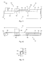
- Fig. 10 an embodiment is shown, in which the device 10 according to the invention is integrated into an overall device 100.
- the overall device 100 has a transport unit 102, which in turn has two transport elements 104 and 106. Of these transport elements 104 and 106 is in Fig. 10 only the transport element 104 recognizable.
- the transport element 104 has horizontally extending conveyor belts 108 and 110, the same applies to the transport element 106, which, viewed from the viewer, lies behind the transport element 104.
- the conveyor belts 108 and 110 rest on one of the standing side edges 37 or 37 'of the envelope 30, the conveyor belts of the second transport elements 106 then on the corresponding opposite edges.
- the envelopes 30 are aligned standing coming from a station and initially transported via their side edges 37, 37 'in the transport unit 102 in the transport direction 20 and thereby already formed into a block 69.
- the envelopes 30 reach a transition region 112. From this transition region 112, the envelopes 30 are transferred into the device 10 according to the invention.
- the envelopes 30 are initially held by the transport unit 102 at their side edges 37, 37 ', but they are then already detected at its upper edge 32 of the vacuum unit 12.
- By moving the conveyor belt 18, these are then moved further in the transport direction 20, for example via brought a transport container 114.
- the slider 76 By operating the slider 76, the products 30 can be pushed away from the vacuum unit and transferred to the transport container 114.
- the vacuum unit 122 has on its underside 123 again a longitudinally approximately rectangular suction opening 124, as well as from Fig. 12 is apparent.
- the vacuum unit 122 is connected to a vacuum source 127 via a connection 126 arranged at an end region.
- the vacuum unit 122 has a Teleskopsaugang 129, the maximum length 131 is shown.
- the Teleskopsaugruc 129 has a first telescopic rail 133 into which a second telescopic rail 135 is retractable, wherein in the second telescopic rail 135 still a third telescopic rail 137 is retractable.
- the first telescopic rail 133 is fixedly connected to an arm 139, via which the vacuum unit 122 is movable or pivotable as a complete unit.
- a drive 143 is arranged, which has two laterally offset parallel spindles 145 and 147, which are accommodated in a common approximately central socket 149.
- the Teleskopsaugruc 129 in its maximum extended position 131, as in FIGS. 11 and 12 is shown, brought out of this and, as described below, in a more or less retracted position. In order not to overload the drawings with these details, this drive is only in Fig. 11 shown.
- the telescopic suction bar 129 can work without the drive 143, then you have to move the extendable end 141 by hand. It is also provided to assist the extension of the telescopic rail by a spring, so that the retraction occurs against the force of the spring. In order to be able to distribute the negative pressure exerted by the negative pressure source 127 uniformly over the entire intake opening 124 in all extended positions, corresponding suction port openings 150, 152 are provided in the second and third telescopic rails 135 and 137, respectively.
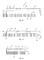
- a row 158 of standing products 28, again letter envelopes in the illustrated embodiment, is provided.
- a diverter blade 160 separates a trailing end of the row 158 from a next row.
- the vacuum unit 122 is now brought over the arm 139 over the row 158, that the immersion fork 156 is immersed from above immediately behind the separator sheet 160 in the series 158, as that from the transition from Fig. 14 to Fig. 15 is apparent.
- the Teleskopsaugruc 129 of the vacuum unit 122 is extended further than the right outer leading end of the Row 158.
- the extended end 141 By operating the drive not shown here, the extended end 141, so the dip fork 154 is applied to this outer end 162 of the row 158, as indicated by an arrow 159.
- the vacuum source 127 the row 158 is sucked, in which case in particular the air between the individual products 28 of the row 158 is sucked through the approximately rectangular suction port 124.
- the row 158 shrinks to a compressed stack 164, like that in FIG Fig. 16 is shown.
- the right end that is to say the immersion fork 154, is continuously tracked, that is to say it is thus under pressure at the right outer end 162 of the compressed stack 164.
- the vacuum unit 122 enters from above into the open end of the container 166. This may be done until the compressed stack 164 comes to rest on the floor 168 of the container 166, or it may be done by keeping it above the floor 168 at a certain distance.
- the compressed stack 164 then either slips completely onto the floor 168, or if it is already standing up, the vacuum unit 122 can be moved upwards in this state, as in FIG Fig. 18 is shown by the arrow 169.
- the compressed stack 164 slightly expands, i. In some cases, air can again enter between the individual products or, in particular, when these are folded products, they spread open again and completely fill the container 166.
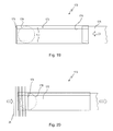
- FIGS. 19 and 20 a third embodiment of a vacuum unit 172 according to the invention is shown.
- the vacuum unit 172 consists of a U-shaped hollow profile, whose undersides of the U still each have inwardly angled edges 177. At one end of the thus formed squeegee 175 is completed. Via a suction opening 178 in the upper side, the vacuum unit 172 is connected to a vacuum source not shown here.
- a cover 176 In the interior of the squeegee 175 can laterally a cover 176 are inserted in the form of a sliding plate, as in Fig. 19 is shown by an arrow. In this case, the cover 176 rests on the inward edges 177.
- the effective cross-section of the suction opening 174 is thus determined by the longitudinal edges of the edges 177, the termination on a left side and by the position of the cover 176. The further the cover 176 is inserted, the smaller the length of the suction opening 174.
- the cover 176 also provides an airtight seal of the squeegee 175 to the right side, from which the cover 176 is inserted.
- Fig. 20 a situation is shown in which the cover 176 is pushed very far into the squeegee 175, so that only a reduced small suction port 174 remains.
- already some products 28 are arranged hanging above the upper edge of the suction opening 174.
- FIGS. 19 and 20 can be stored in different containers by sections insertion of the cover 176 gradually blocks.
- each corresponding to letter post envelopes a postal code area, attached to the bottom 173 can be replaced by each corresponding rapid advancement of the cover 176 gradually such a block and into an underlying Transport containers are delivered.
Abstract
Description
Die vorliegende Erfindung betrifft eine Vorrichtung zum Transportieren von flächigen Produkten, die zumindest über einen Abschnitt eine Kante aufweisen.The present invention relates to a device for transporting flat products which have an edge over at least a portion.
Unter flächigen Produkten, die zumindest eine über einen Abschnitt verlaufende Kante aufweisen, kann man beispielsweise Druckereierzeugnisse, Kartons, Zuschnitte, Faltschachteln, Platten, Zeitungen, Prospekte, Verpackungen, Briefkuverts etc. verstehen. All diesen Produkten ist gemein, dass sie flächig ausgebildet sind, wobei flächig hier nicht unbedingt eben bedeutet, sie können auch gebogen oder wellig verlaufen, sie müssen aber eine über einen gewissen Abschnitt definiert verlaufende Kante aufweisen. Derartige Erzeugnisse werden meist von einer vorangegangenen Station, beispielsweise einer Druckvorrichtung, einer Falzvorrichtung einer Stanzvorrichtung oder in Fällen von Briefkuverts einer Kuvertieranlage, als ein Strom von Produkten ausgegeben.Under flat products, which have at least one edge extending over a section, one can understand, for example, printed products, cartons, blanks, folding boxes, plates, newspapers, brochures, packaging, envelopes, etc. All these products have in common that they are formed flat, which flat does not necessarily mean even here, they can also be curved or wavy, but they must have a defined section over a certain edge. Such products are usually from a previous one Station, such as a printing device, a folding device of a punching device or in cases of envelopes an inserter, issued as a stream of products.
Zur weiteren Handhabung soll dieser Strom in einzelne Einheiten unterteilt werden und diese Einheiten zum Beispiel in ein Behältnis oder dergleichen übergeführt werden.For further handling, this stream is to be subdivided into individual units and these units are transferred, for example, into a container or the like.
Es können auch Banderolier- oder Verpackungsvorgänge anschließend stattfinden, entscheidend ist, dass eine bestimmte Menge bzw. Chargengröße bewegt werden muss.Banderolier- or packaging operations can then take place, it is crucial that a certain amount or batch size must be moved.
Im Falle von Briefkuverts werden diese anhand bestimmter Daten, wie zum Beispiel Postleitzahlenbereiche, bis dato noch von Hand aus einem kontinuierlichen Strom aussortiert und in entsprechende Transportbehälter überführt.In the case of envelopes, these are still sorted by hand from a continuous stream on the basis of certain data, such as postal code areas, and transferred to corresponding transport containers.
Bei anderen Erzeugnissen, beispielsweise Faltschachteln, werden Zuschnitte nach dem Ausstanzen durch Verkleben schon in eine Vorform gebracht, die aber noch flächig und nicht dreidimensional ist.For other products, such as cartons, blanks after punching by gluing are already brought into a preform, which is still flat and not three-dimensional.
Diese Zuschnitte werden dann beispielsweise in Chargengrößen von mehreren hundert Stück an einen Befüller überbracht.These blanks are then delivered to a filler, for example in batch sizes of several hundred pieces.
Nimmt man als Beispiel eine Zahnpastaverpackung, so wird diese Schachtel als Stanzblatt hergestellt, über eine Längskante verklebt und als noch mehr oder weniger zweidimensionales flächiges Produkt zu dem Befüller weiter transportiert. Dort wird dann das flächige Produkt zu einem dreidimensionalen Körper aufgestellt, befüllt, indem eine Zahnpastatube eingeschoben wird, und das Behältnis wird am oberen und unteren Ende verschlossen.Taking as an example a toothpaste packaging, this box is produced as a punching sheet, glued over a longitudinal edge and further transported as even more or less two-dimensional sheet product to the filler. There, the sheet product is then placed in a three-dimensional body, filled by a toothpaste tube is inserted, and the container is closed at the top and bottom.
In der Praxis werden solche vorkonfektionierte Schachteln beispielsweise in Chargengrößen von etwa 250 Packungen als horizontal erstreckender Stapel angeliefert. Die Bedienungsperson ergreift sich einen solchen Stapel, der durchaus eine Länge von bis zu einem Meter haben kann und mehrere Kilogramm wiegt, legt die Hände an beiden seitlichen Enden an, presst den Stapel etwas zusammen, hebt diesen von der Transportvorrichtung ab und überbringt diesen Stapel in ein Behältnis.In practice, such prefabricated cartons are delivered, for example, in batch sizes of about 250 packages as a horizontally extending stack. The operator grasps such a stack, which may well be up to one meter in length and weighs several kilograms, places the hands on both lateral ends, compresses the stack a bit, lifts it off the conveyor, and delivers that stack into a container.
Diese Transportart ist nicht nur sehr mühsam, sondern führt auch dazu, dass, insbesondere wenn die Handhabungsperson nach mehreren Stunden ermüdet ist, ein solcher Stapel entgleiten kann, wenn nicht mehr genügend Kraft vorhanden ist, diesen von außen zusammenzupressen.This type of transport is not only very tedious, but also leads to the fact that, especially when the operator is fatigued after several hours, such a stack can slip out if there is not enough force to compress it from the outside.
Dies führt dann dazu, dass beispielsweise 250 herab gefallene einzelne flächige Produkte wieder aufgesammelt, und insbesondere wenn sie dann später einer Weiterverarbeitung zugeführt werden, in der diese eine bestimmte Orientierung haben müssen, entsprechend sortiert werden müssen.This then results in that, for example, 250 fallen down individual flat products picked up again, and especially if they are then fed to a subsequent processing in which they must have a certain orientation must be sorted accordingly.
Dies ist sehr mühevoll und zeitaufwändig und unterbricht für längere Zeit den Transportvorgang.This is very laborious and time consuming and interrupts the transport process for a long time.
Es ist daher Aufgabe der vorliegenden Erfindung, hier Abhilfe zu schaffen und eine Vorrichtung zum Transportieren einer Reihe von solchen flächigen Produkten zu schaffen, bei der dieser Vorgang automatisiert durchgeführt werden kann.It is therefore an object of the present invention to remedy this situation and to provide a device for transporting a number of such flat products, in which this process can be carried out automatically.
Erfindungsgemäß wird die Aufgabe dadurch gelöst, dass eine Unterdruckeinheit vorgesehen ist, die an einer Unterseite eine längs verlaufende Ansaugöffnung aufweist, durch die Luft über eine Unterdruckquelle ansaugbar ist, wobei eine Reihe von zu transportierenden flächigen Produkten mittels eines durch Unterdruck erzeugten Sogeffekts über deren eine Kante an die Unterseite anhängbar sind, und wobei die Kante beim Transport an der längs verlaufenden Ansaugöffnung anliegt und zu dieser quer ausgerichtet ist.According to the invention, the object is achieved in that a vacuum unit is provided which has a longitudinal suction opening on a bottom through which air can be sucked via a vacuum source, wherein a series of planar products to be transported by means of a suction effect generated by negative pressure on one edge can be attached to the underside, and wherein the edge during transport bears against the longitudinally extending suction opening and is aligned transversely thereto.
Es wurde in zahlreichen Versuchen festgestellt, dass es möglich ist, eine Reihe an solchen zu transportierenden flächigen Produkten, die eine über einen Abschnitt definiert verlaufende Kante aufweisen, an eine solche Unterdruckeinheit anzuhängen, und zwar so, dass sich deren definierte Kante quer zur längs verlaufenden Ansaugöffnung erstreckt.It has been found in numerous experiments that it is possible to attach a series of such flat products to be transported, which have an edge extending over a section, to such a vacuum unit in such a way that their defined edge is transverse to the longitudinal one Suction opening extends.
Wenngleich die einzelnen Kanten eines flächigen Produktes eine relativ geringe Angriffsfläche darbieten, wurde festgestellt, dass man eine Reihe von solchen Produkten dennoch sehr fest haftend an eine Ansaugöffnung anlegen kann, so dass diese an der Unterseite der Unterdruckeinheit hängen.Although the individual edges of a sheet product offer a relatively low attack surface, it has been found that a number of such products can still be very firmly attached to a suction opening, so that they hang on the underside of the vacuum unit.
Dabei wurde festgestellt, dass durch die Unterdruckquelle Luft, die in oder zwischen den flächigen Produkten vorhanden ist, zunächst abgesaugt wird, wodurch es möglich ist, die flächigen Produkte sehr eng aneinander schmiegend aufzureihen. Dadurch liegen dann die Kanten relativ eng in einer gleichen Ausrichtung nebeneinander, so dass, über einen gewissen Längenabschnitt gesehen, sich ein quasi mehr oder weniger geschlossener flächiger Körper ergibt, der aus zahlreichen nebeneinander liegenden Kantenabschnitten der Produkte aufgebaut ist. Jede Kante hat eine endliche Breite, die zum Beispiel durch die Dicke des Materials, oder bei Falzkanten durch die Dicke des Falzes bestimmt ist. In der aneinanderliegenden Form kann, bei entsprechender Saugleistung, eine große Anzahl solcher flächiger Produkte fest haftend an die Unterdruckeinheit angebracht werden. In diesem Zustand ist es nun möglich, die so an der Unterseite der Unterdruckeinheit hängenden Produkte an eine andere Stelle, beispielsweise zu einem Behältnis, zu transportieren.It was found that air is sucked out by the vacuum source, which is present in or between the sheet-like products, whereby it is possible to string the sheet-like products very tightly against each other. As a result, then the edges are relatively close in a same orientation next to each other, so that, seen over a certain length, results in a quasi more or less closed planar body, which is composed of numerous adjacent edge portions of the products. Each edge has a finite width determined, for example, by the thickness of the material, or at fold edges by the thickness of the seam. In the adjacent mold can, with appropriate suction, a large number of such sheet products are adhered to the vacuum unit. In this state, it is now possible to transport the so hanging on the bottom of the vacuum unit products to another location, for example, to a container.
In einer weiteren Ausgestaltung der Erfindung ist dazu die Unterdruckeinheit mit den anhängenden flächigen Produkten bewegbar.In a further embodiment of the invention, the vacuum unit with the attached sheet-like products is movable for this purpose.
Diese Maßnahme hat den Vorteil, dass nun der Zusammenbau aus der Unterdruckeinheit und den daran anhängenden flächigen Produkten bewegt werden kann, beispielsweise von einem Transportband, von dem die Reihe an flächigen Produkten angeliefert wird, zu einem Behälter zum Weitertransport.This measure has the advantage that now the assembly of the vacuum unit and the adhering flat products can be moved, for example, from a conveyor belt, from which the series is delivered to flat products, to a container for further transport.
Dazu ist in einer weiteren Ausgestaltung der Erfindung die Unterdruckeinheit mit einer Transporteinheit verbunden, durch die die Unterdruckeinheit zumindest zwischen einer ersten und einer zweiten Position überbringbar ist.For this purpose, in a further embodiment of the invention, the vacuum unit is connected to a transport unit, by means of which the vacuum unit can be transferred at least between a first and a second position.
Die Transporteinheit ist den Gegebenheiten angepasst, das kann beispielsweise ein verschwenkbarer Umsetzarm sein, der die Unterdruckeinheit nur umsetzt, die Transporteinheit kann dann auch eine komplett verfahrbare Einheit sein, die die flächigen Produkte zu einer beliebigen abseits gelegenen Stelle verbringt.The transport unit is adapted to the circumstances, which may for example be a pivotable transfer arm, which only implements the vacuum unit, the transport unit can then be a completely movable unit that spends the sheet products to any remote location.
In einer weiteren Ausgestaltung der Erfindung ist ein wirksamer Ansaugquerschnitt der Ansaugöffnung veränderbar.In a further embodiment of the invention, an effective intake cross section of the intake opening is variable.
Diese Maßnahme hat nun mehrere Vorteile.This measure now has several advantages.
Ein erster Vorteil besteht darin, dass eine Veränderung der wirksamen Ansaugöffnung es ermöglicht, an unterschiedlich lange Reihen von einander angereihten flächigen Produkten anpassen zu können. Der Begriff "Veränderung der wirksamen Ansaugöffnung" bedeutet, dass der Ansaugquerschnitt der Ansaugöffnung über die Luft angesaugt werden kann, insbesondere in seiner Längserstreckung veränderbar ist.A first advantage is that a change in the effective suction opening makes it possible to adapt to differently long rows of aligned flat products. The term "modification of the effective intake opening" means that the intake cross section of the intake opening can be sucked in via the air, in particular being variable in its longitudinal extent.
Dabei kann an unterschiedliche Produkte angepasst werden, da beispielsweise 250 aneinander gereihte Briefkuverts eine andere Länge aufweisen können als beispielsweise 250 aneinander liegende, mit einer relativ dicken Falzkante versehene Verpackungen oder dergleichen.In this case, it is possible to adapt to different products since, for example, 250 lined envelopes can have a different length than, for example, 250 contiguous packages provided with a relatively thick folded edge or the like.
Ein weiterer Vorteil ist, dass bei einem bestimmten flächigen Produkt an eine Schrumpfung der ausgänglichen Reihenlänge angepasst werden kann, wenn zwischen den einzelnen flächigen Produkten vorhandene Luft abgesaugt wurde.Another advantage is that it can be adapted to a shrinkage of the original row length for a given sheet product, if existing air was sucked between the individual sheet products.
Für einen effizienten und ökonomischen Betrieb ist es notwendig, dass möglichst wenig Totvolumen eingesaugt wird, d.h. Luftmengen, die zwischen oder am vorderen oder hinteren Ende eines Stapels in die Ansaugöffnung eintreten können, sollen möglichst gering sein. Kann dieses Totvolumen möglichst gering gehalten werden, bilden sich zwischen den quer verlaufenden Kanten und der Ansaugöffnung solche Unterdruckverhältnisse aus, dass sowohl das einzelne flächige Produkt als auch die ganze Reihe fest an der Ansaugöffnung gehalten wird.For efficient and economical operation it is necessary that as little dead volume as possible is sucked in, i.e. Air quantities that can enter into the intake between or at the front or rear end of a stack, should be as low as possible. If this dead volume can be kept as low as possible, such negative pressure conditions are formed between the transverse edges and the intake opening so that both the individual flat product and the entire row are held firmly against the intake opening.
Ist beispielsweise aufgrund der Geometrie oder dem Herstellvorgang der flächigen Produkte eine relativ große Menge an Luft im Produkt oder zwischen zwei nebeneinander liegenden Produkten vorhanden, so wird diese Luft über die Ansaugöffnung abgesaugt. Dabei schrumpft die Länge des Stapels. Durch die Veränderbarkeit der Länge der Ansaugöffnung kann hier entsprechend angepasst werden, d.h. die Länge der Ansaugöffnung verkürzt werden, so dass am Ende des Stapels kein Bereich der Ansaugöffnung offen bleibt, durch die dann hauptsächlich Luft eingesaugt würde.If, for example, due to the geometry or the manufacturing process of the sheet-like products, a relatively large amount of air is present in the product or between two adjacent products, this air is sucked out via the suction opening. This shrinks the length of the stack. Due to the variability of the length of the suction opening can be adjusted accordingly here, i. the length of the suction opening are shortened, so that at the end of the stack no area of the suction opening remains open, through which then mainly air would be sucked.
In einer Ausgestaltung der Erfindung weist die Vorrichtung ferner eine verschiebbare Abdeckung auf, durch die Bereiche der Ansaugöffnung abdeckbar sind.In one embodiment of the invention, the device further comprises a sliding cover, can be covered by the areas of the suction port.
Dies ist eine mechanisch einfache Lösung zum Beispiel der Anpassung der Länge der Ansaugöffnung. Es kann auch eine Variation der Breite der Ansaugöffnung durchgeführt werden.This is a mechanically simple solution, for example the adaptation of the length of the suction opening. Also, a variation of the width of the suction port can be performed.
Diese verschiebbare Abdeckung kann nicht nur dazu herangezogen werden, um eine Größenanpassung der Ansaugöffnung sicherzustellen, man kann durch Einbringen der Abdeckung kurzfristig den haftenden Kontakt zwischen der Ansaugöffnung und den anhängenden Produkten unterbrechen, so dass diese dann herabfallen. Dabei können nur Bereiche abgedeckt werden oder die komplette Ansaugöffnung.This sliding cover can not only be used to ensure a sizing of the suction, you can break the adhesive contact between the suction and the attached products in the short term by introducing the cover so that they then fall down. Only areas can be covered or the complete intake opening.
Dies kann gezielt durchgeführt werden, wenn die Produkte beispielsweise mit der Unterdruckeinheit über ein Behältnis gebracht wurden und diese von der Unterdruckeinheit weg bewegt werden sollen.This can be carried out selectively, if the products were brought, for example, with the vacuum unit on a container and they are to be moved away from the vacuum unit.
In einer weiteren Ausgestaltung der Erfindung ist die Unterdruckeinheit als eine Saugleiste ausgebildet, an der an einem Ende ein Sauganschluss vorhanden ist und von deren anderem Ende her die verschiebbare Abdeckung einbringbar ist.In a further embodiment of the invention, the vacuum unit is designed as a suction strip on which at one end a suction port is present and from the other end of the sliding cover can be introduced.
Diese Maßnahme hat den Vorteil, dass durch mechanisch sehr einfache Mittel sowohl die Längenanpassung der Ansaugöffnung möglich ist als auch ein Ablösen der Produkte. Diese verschiebbare Abdeckung zeigt aber noch einen weiteren Vorteil, man kann beispielsweise die Abdeckung zunächst sehr weit in die Saugleiste einschieben, so dass die Ansaugöffnung praktisch vollständig geschlossen oder nur geringfügig geöffnet ist. Möchte man die flächigen Produkte nach und nach an die Unterdruckeinheit anbringen, so kann man dann die Abdeckung nach und nach verschieben und dabei die Ansaugöffnung immer länger machen, so dass nach und nach immer mehr Produkte angehängt werden können.This measure has the advantage that by mechanically very simple means both the length adjustment of the suction port is possible and a detachment of the products. But this sliding cover shows yet another advantage, you can, for example, first push the cover very far into the squeegee, so that the suction port is almost completely closed or only slightly open. If you want to attach the flat products gradually to the vacuum unit, then you can then move the cover gradually and thereby make the intake longer and longer, so that gradually more and more products can be attached.
In einer weiteren Ausgestaltung der Erfindung weist die Unterdruckeinheit eine Teleskopsaugleiste auf, durch die die Länge der Ansaugöffnung an der Unterseite veränderbar ist.In a further embodiment of the invention, the vacuum unit on a Teleskopsaugleiste, through which the length of the suction opening is variable at the bottom.
Diese Maßnahme hat den Vorteil, dass über diese Teleskopausgestaltungen die Längenveränderung mechanisch sehr einfach durchgeführt werden kann.This measure has the advantage that the length change can be carried out mechanically very simply by means of these telescope designs.
In einer weiteren Ausgestaltung der Erfindung ist die Längenveränderung durch einen Antrieb regelbar.In a further embodiment of the invention, the change in length can be regulated by a drive.
Diese Maßnahme hat den Vorteil, dass durch diesen Antrieb dies voll automatisch durchgeführt werden kann. Der Antrieb wird zum Beispiel so geregelt, dass er zunächst einen solchen Längenbereich der Ansaugöffnung freigibt, wie das für den Stapel notwendig ist. Wird ein Stapel einer bestimmten Länge angeliefert, wird dies eingegeben, so dass der Antrieb dann zunächst einmal die Ansaugöffnung in dieser Länge freigibt. Wie zuvor erwähnt, schrumpft der Stapel mehr oder weniger durch Anlegen des Unterdrucks, so dass dann durch eine entsprechende Steuerung die Länge nachgeregelt werden kann.This measure has the advantage that this drive can be performed fully automatically. The drive is regulated, for example, so that it first releases such a length range of the suction opening, as is necessary for the stack. If a stack of a certain length delivered, this is entered, so that the drive then first releases the suction port in this length. As mentioned above, the stack shrinks more or less by applying the negative pressure, so that then the length can be readjusted by an appropriate control.
In einer weiteren Ausgestaltung der Erfindung ist ein perforierter Transportriemen an der Ansaugöffnung angeordnet, der in einer Transportrichtung längs der Längserstreckung der Ansaugöffnung bewegbar ist, so dass die flächigen Produkte über die Oberkante an dem perforierten Transportriemen hängend transportierbar sind.In a further embodiment of the invention, a perforated conveyor belt is arranged on the suction opening, which is movable in a transport direction along the longitudinal extension of the suction opening, so that the sheet-like products are transported over the top edge of the perforated conveyor belt hanging.
Diese Maßnahme hat den Vorteil, dass in dieser Ausgestaltung nicht nur die flächigen Produkte über ihre Kante an die Ansaugöffnung angehängt werden können, sondern durch das Zwischenlegen eines perforierten Transportriemens können diese auch noch längs der Längserstreckung der Ansaugöffnung transportiert werden.This measure has the advantage that in this embodiment not only the flat products can be attached to the suction opening via their edge, but by interposing a perforated conveyor belt, they can also be transported along the longitudinal extension of the suction opening.
Diese Maßnahme hat den erheblichen Vorteil, dass die Transportvorrichtung an sich dann stationär sein kann, der Längentransport durch den bewegbaren perforierten Transportriemen erfolgt.This measure has the considerable advantage that the transport device can then be stationary in itself, the longitudinal transport is carried out by the movable perforated conveyor belt.
In einer weiteren Ausgestaltung der Erfindung weist die Ansaugöffnung eine Mehrzahl an Langlochöffnungen auf, entlang derer die Perforation des Transportriemens läuft.In a further embodiment of the invention, the suction opening has a plurality of slot openings along which runs the perforation of the conveyor belt.
Durch Vorsehen eines bestimmten Perforationsmusters in dem Transportriemen kann auf die Geometrie der Kante des Produktes eingegangen werden, über die das flächige Produkt angehängt werden soll. Die Größe und Anzahl der Perforationen wird dann so berechnet, dass ein ausreichender Unterdruck sich zwischen der Kante und dem Transportriemen etabliert, so dass das flächige Produkt ausreichend fest hängt und gleichzeitig durch den Transportriemen transportiert werden kann. Aufgrund der Tatsache, dass die Perforation längs den Langlochöffnungen laufen, wird sichergestellt, dass, über den Transportweg gesehen, immer ein Sog bzw. Unterdruck durch die Perforation in dem Transportriemen ausgeübt wird, und somit auch auf das an dem Transportriemen hängende flächige Produkt.By providing a specific perforation pattern in the conveyor belt, one can discuss the geometry of the edge of the product over which the sheet product is to be attached. The size and number of perforations is then calculated so that a sufficient negative pressure between the edge and the conveyor belt established so that the sheet product is sufficiently strong and can be transported simultaneously through the conveyor belt. Due to the fact that the perforation run along the slot openings, it is ensured that, viewed over the transport path, a suction or negative pressure is always exerted by the perforation in the conveyor belt, and thus also on the flat product hanging on the conveyor belt.
In einer weiteren Ausgestaltung der Erfindung ist die Perforation des Transportriemens durch Löcher gebildet, die als Reihen von Löchern sich sowohl in Längs- als auch in Querrichtung der Ansaugöffnung erstrecken und die mit den Langlochöffnungen kommunizieren.In a further embodiment of the invention, the perforation of the conveyor belt is formed by holes which extend as rows of holes in both the longitudinal and transverse direction of the suction opening and communicate with the slot openings.
Dies reflektiert die zuvor schon angesprochene vorteilhafte Maßnahme, nämlich dass über die gesamte Transportlänge des Transportriemens gesehen gute Unterdruckbedingungen geschaffen werden können, die sicherstellen, dass ein flächiges Produkt über seine Kante ausreichend fest am Transportriemen hängt.This reflects the previously mentioned advantageous measure, namely that over the entire transport length of the transport belt good vacuum conditions can be created, which ensure that a flat product depends on its edge sufficiently firmly on the conveyor belt.
In einer weiteren Ausgestaltung der Erfindung weist die Vorrichtung ferner zumindest einen bewegbaren Schieber auf, durch den die an der Unterdruckeinheit hängenden flächigen Produkte wegdrückbar sind.In a further embodiment of the invention, the device further comprises at least one movable slide, through which the flat products hanging on the vacuum unit can be pushed away.
Diese Maßnahme hat den Vorteil, dass durch den Schieber die flächigen Produkte etwas von der Ansaugöffnung wegbewegt werden können, so dass der haftende Zustand unterbrochen wird. Dadurch lösen sich die anhaftenden Produkte von der Ansaugöffnung oder von dem Transportriemen und können nach unten in ein Behältnis aufgrund der Schwerkraft überbracht werden. Der Schieber kann dann so ausgestaltet sein, dass er diesen Ablöseweg begleitet oder richtet, so dass die herab fallenden Produkte zielgerichtet in ein Behältnis überbracht werden können.This measure has the advantage that the planar products can be moved away from the suction opening somewhat by the slide, so that the adhesive state is interrupted. As a result, the adhering products detach from the suction port or from the transport belt and can be delivered down into a container due to gravity. The slider can then be designed so that it accompanies or directs this Ablöseweg, so that the falling down products can be delivered purposefully into a container.
Dazu ist vorteilhaft, dass der Schieber mit seitlich über die Unterdruckeinheit vorstehenden Oberkanten der flächigen Produkte in Eingriff bringbar ist und diese nach unten von der Ansaugöffnung wegdrückt.For this purpose, it is advantageous that the slide can be brought into engagement with laterally over the vacuum unit projecting upper edges of the sheet-like products and pushes them downwards from the suction opening.
Dies ist eine besonders ökonomische und mechanisch einfache Ausgestaltung, um die an der Ansaugöffnung anhängenden Produkte von der Unterdruckeinheit abzulösen.This is a particularly economical and mechanically simple embodiment for detaching the products attached to the intake opening from the vacuum unit.
In einer weiteren Ausgestaltung der Erfindung weist die Unterdruckeinheit einen Unterbrecher auf, über den ein an der Ansaugöffnung angelegter Unterdruck zumindest kurzzeitig unterbrechbar ist.In a further embodiment of the invention, the vacuum unit has a breaker, via which a vacuum applied to the suction opening can be interrupted at least for a short time.
Diese Maßnahme hat den Vorteil, dass der zuvor beschriebene Ablösevorgang durch ein Unterbrechen der Ansaugleistung gesteuert wird, so dass dann dieser Ablösevorgang ausgelöst wird.This measure has the advantage that the detachment process described above is controlled by interrupting the intake, so that then this detachment process is triggered.
Es ist möglich, beide Maßnahmen zu kombinieren, d.h. sowohl eine kurzzeitige Unterbrechung als auch zusätzlich einen Schieber vorzusehen, insbesondere wenn dieser auch noch führende Aufgaben erfüllt, um die herab fallenden Produkte ordentlich ausgerichtet in ein Behältnis zu überbringen.It is possible to combine both measures, i. provide both a short-term interruption and in addition a slide, especially if this also fulfills leading tasks to bring the falling down products neatly aligned in a container.
Es versteht sich, dass die vorstehend genannten und die nachstehend noch zu erläuternden Merkmale nicht nur in den jeweils angegebenen Kombinationen, sondern auch in anderen Kombinationen oder in Alleinstellung einsetzbar sind, ohne den Rahmen der vorliegenden Erfindung zu verlassen.It is understood that the features mentioned above and those yet to be explained not only in the respective combinations indicated, but also in other combinations or alone, without departing from the scope of the present invention.
Die Erfindung wird nachfolgend anhand einiger ausgewählter Ausführungsbeispiele in Zusammenhang mit den Zeichnungen näher beschrieben und erläutert. Es zeigen:
- Fig. 1
- ein erstes Ausführungsbeispiel einer erfindungsgemäßen Vorrichtung in einer Seitenansicht,
- Fig. 1a
- die Vorrichtung aus
Fig. 1 , stark schematisiert, in einer Draufsicht, - Fig. 2a und 2b
- schematische Darstellungen eines flächigen Produktes in Form eines Briefkuverts,
- Fig. 3a und 3b
- eine erste Blende, die in eine Ansaugöffnung einsetzbar ist, in Draufund Seitenansicht,
- Fig. 4a und 4b
- eine zweite Blende in einer Drauf- und einer Seitenansicht,
- Fig. 5a und 5b
- einen Zusammenbau aus erster und zweiter Blende,
- Fig. 6
- eine Draufsicht auf einen Ausschnitt eines perforierten Transportriemens, an dem ein flächiges Produkt hängt,
- Fig. 7
- eine Draufsicht auf den Transportriemen von
Fig. 6 , der auf dem inFig. 5a und 5b dargestellten Zusammenbau aus erster und zweiter Blende liegt, - Fig. 8 und 8a
- eine schematische Seitenansicht des ersten Ausführungsbeispiels der Vorrichtung mit zusätzlichen Schiebern sowie deren Funktionsweise,
- Fig. 9
- eine stark vereinfachte Draufsicht der Vorrichtung von
Fig. 8 mit den zusätzlichen Schiebern, - Fig. 10
- eine Darstellung der erfindungsgemäßen Unterdruckeinheit in einer erfindungsgemäßen Transporteinrichtung,
- Fig. 11
- stark schematisch eine Seitenansicht eines zweiten Ausführungsbeispiels einer Unterdruckeinheit in Form einer Teleskopsaugleiste,
- Fig. 12
- eine Ansicht der Teleskopsaugleiste von unten in Richtung auf die Ansaugöffnung,
- Fig. 13
- eine stirnseitige Ansicht der Teleskopsaugleiste,
- Fig. 14
- die Teleskopsaugleiste von
Fig. 11 in einem Betriebszustand kurz vor dem Einstechen in eine Reihe an flächigen Produkten, - Fig. 15
- eine Situation, in der die Teleskopsaugleiste in eine Reihe an flächigen Produkten eingestochen ist und die Produkte über deren Oberkante an der Ansaugöffnung angesaugt sind,
- Fig. 16
- einen weiteren Betriebszustand der Teleskopsaugleiste mit geschrumpften Stapel,
- Fig. 17
- einen Betriebszustand der Teleskopsaugleiste beim Einfahren in einen Behälter für die Produkte,
- Fig. 18
- einen Betriebszustand der Teleskopsaugleiste nach Abgabe der Produkte in den Behälter,
- Fig. 19
- ein drittes Ausführungsbeispiel einer Unterdruckeinheit in Unteransicht auf deren Ansaugöffnung gesehen, die mit einer verschiebbaren Abdeckung versehen ist, und
- Fig. 20
- einen Betriebszustand des dritten Ausführungsbeispiels der Saugleiste beim Anbringen von flächigen Produkten an die Ansaugöffnung.
- Fig. 1
- A first embodiment of a device according to the invention in a side view,
- Fig. 1a
- the device off
Fig. 1 , highly schematic, in a plan view, - Fig. 2a and 2b
- schematic representations of a sheet product in the form of a letter envelope,
- Fig. 3a and 3b
- a first orifice, which can be inserted into a suction opening, in a top and side view,
- Fig. 4a and 4b
- a second panel in a top view and a side view,
- Fig. 5a and 5b
- an assembly of first and second aperture,
- Fig. 6
- a top view of a section of a perforated conveyor belt to which a flat product depends,
- Fig. 7
- a plan view of the conveyor belt of
Fig. 6 who is on the inFig. 5a and 5b shown assembly of first and second aperture, - Fig. 8 and 8a
- a schematic side view of the first embodiment of the device with additional sliders and their operation,
- Fig. 9
- a greatly simplified plan view of the device of
Fig. 8 with the additional sliders, - Fig. 10
- a representation of the vacuum unit according to the invention in a transport device according to the invention,
- Fig. 11
- very schematically a side view of a second embodiment of a vacuum unit in the form of a Teleskopsaugleiste,
- Fig. 12
- a view of the telescopic suction strip from below in the direction of the suction opening,
- Fig. 13
- an end view of the telescopic suction,
- Fig. 14
- the telescopic suction bar of
Fig. 11 in an operating state shortly before piercing a series of flat products, - Fig. 15
- a situation in which the telescopic suction strip is inserted into a series of flat products and the products are sucked over the upper edge thereof at the suction opening,
- Fig. 16
- another operating state of the telescopic suction strip with shrunken stack,
- Fig. 17
- an operating state of the telescopic suction bar when entering a container for the products,
- Fig. 18
- an operating state of the telescopic suction bar after dispensing of the products into the container,
- Fig. 19
- a third embodiment of a vacuum unit seen in bottom view on the suction port, which is provided with a sliding cover, and
- Fig. 20
- an operating state of the third embodiment of the squeegee when attaching sheet products to the suction port.
Ein in den
Wie insbesondere in
Die Unterdruckeinheit 12 weist ferner einen perforierten Transportriemen 18 auf, der in Längsrichtung der Ansaugöffnung 14 in eine Transportrichtung 20 geführt wird. Der Transportriemen 18 läuft dabei über Rollen 22 und 24, durch die der Transportriemen 18 entlang der Unterseite 13 der Unterdruckeinheit 12 bewegt wird. Der Transportriemen 18 ist als ein Endlostransportriemen ausgebildet.The
Die Vorrichtung 10 dient dazu, dass flächige Produkte 28, die zumindest über einen gewissen Abschnitt eine definierte Kante 32 aufweisen, durch einen Unterdruck an dem Transportriemen 18 hängend angebracht werden und von diesem in die Transportrichtung 20 transportiert werden.The
Als ein Beispiel für ein derartiges flächiges Produkt 28 ist in
Ferner sind eine Oberkante 32 und eine Unterkante 35 vorhanden, die insgesamt gesehen das etwa rechteckförmige Briefkuvert 30 umgrenzen.Furthermore, an
Ein Abschnitt der Oberkante 32 verläuft dabei geradlinig, so dass dieses Briefkuvert 30 in der in
Die Anordnung der flächigen Produkte an der Unterseite 13 der Unterdruckeinheit wird erfindungsgemäß so realisiert, dass ein entsprechender Unterdruck an die Ansaugöffnung 14 angelegt wird. Dieser Unterdruck sorgt für einen Sogeffekt. Dieser Sogeffekt hat zur Folge, dass ein Volumenstrom an Luft in die Ansaugöffnung 14 eintritt.The arrangement of the sheet-like products on the
In den
In
Die gegenüberliegenden kurzen Enden 52 und 54 weisen dieselbe Breite wie die Enden 46 und 48 der ersten Blende 38 auf, so dass die zweite Blende 40 passend auf die erste Blende 38 gelegt werden kann, wie das in den
In
Der Transportriemen 18 weist zwei gegenüberliegende Ränder 62 und 64 auf, die parallel zur Transportrichtung 20 verlaufen. Der Transportriemen 18 weist als Perforation Löcher 66 auf. Diese kreisrunden Löcher 66 sind in Reihen 68 angeordnet, wobei die fünf Reihen 68 so angeordnet sind, dass diese entlang der durch die Langlochöffnungen von erster und zweiter Blende gebildeten Kanäle 61 laufen.The
Dabei ist jede Reihe 68 aus zwei Unterreihen 70 aufgebaut, die auf Lücke gesetzt sind, d.h. die Öffnungen einer Unterreihe 70 liegen jeweils in Lücken zwischen den Öffnungen der benachbarten Unterreihe 70. Stellt man sich wie in
In
Dabei werden mehrere Produkte 28 in einer Reihe stehend an die Unterseite 13 der Unterdruckeinheit 12 gebracht, wie das in
In den
Der Schieber 76 weist zwei Schieberpaare 80 auf, die beidseits der Unterdruckeinheit 12 an die Oberseite des Blockes 69 angelegt werden können und diesen vom haftenden Kontakt mit dem Transportriemen 18 bzw. der Unterdruckeinheit 12 lösen. In
Im Transportmodus funktioniert der Unterbrecher 82 so, dass der notwendige Unterdruck zur Verfügung gestellt wird, so dass die Produkte 28 fest haftend am Transportriemen 18 anliegen. Zum Ablegen oder Überbringen der Produkte 28 in ein Behältnis kann über eine Steuereinheit 86 und entsprechende Signalleitungen 90, 88 und 84 der Unterdruck kurzzeitig so weit unterbrochen werden, dass der Sogeffekt unterbrochen oder abgeschwächt wird, so dass die Produkte 28 vom Transportriemen 18 beispielsweise in ein Behältnis abfallen.In transport mode, the
Dies kann noch synchron mit der Bewegung des Schiebers 76 gekoppelt werden, so dass dieser die Produkte 28 ganz gezielt in ein Behältnis überführt.This can still be coupled in synchronism with the movement of the
Dies kann bei laufendem Transportriemen 18 erfolgen oder der Transportriemen 18 wird zu diesem Vorgang kurzzeitig angehalten, wobei dies über die Steuereinheit 86 erfolgt.This can be done with the
Die Steuereinheit 86 kann Daten von beliebigen, hier nicht näher bezeichneten Einheiten erhalten, wie das beispielsweise durch den Pfeil 90 angedeutet ist. Diese Informationen können beispielsweise in Bezug auf Briefkuverts Postleitzahlen oder Postleitzahlenbereiche sein, nach denen die Briefkuverts aufgeteilt werden sollen. Ist beispielsweise ein Block 69 aus Briefkuverts 28' eines bestimmten Postleitzahlenbereichs gebildet, kann der Transportriemen kurzzeitig etwas schneller bewegt werden, so dass zu den nachfolgenden Produkten 28 eine Lücke 71 entsteht.The
Dieser Block 69 kann dann ganz definiert von dem Schieber 76 abgeschoben werden. Dabei ist es dann auch unerheblich, ob dieser Block 69 so lang ist wie dargestellt oder auch kürzer. Der Schieber 76 bzw. die Schieberpaare 80 können auch so ausgebildet sein, dass sie sich über die gesamte maximale Länge eines anzuhängenden Blockes erstrecken. Die Länge der Schieberpaare 80 kann auch veränderbar sein.This
Die Unterdruckeinheit 12 kann variabel an unterschiedliche Produkte 28 angepasst werden, also an unterschiedlich breite und schwere Produkte, indem zum einen entweder der Unterdruck variiert wird, oder entsprechend andere Blendenelemente und Transportriemen eingesetzt werden.The
In
Dies kann auch durch den zuvor beschriebenen Unterbrecher 82 bzw. durch die Steuereinheit 86 erfolgen oder unterstützt werden.This can also be done or supported by the previously described
In den
Ein wesentliches Bauelement der Vorrichtung 120 ist die Unterdruckeinheit 122. Die Unterdruckeinheit 122 weist an ihrer Unterseite 123 wieder eine längs verlaufende etwa rechteckförmige Ansaugöffnung 124 auf, wie das auch aus
Über einen an einem Endbereich angeordneten Anschluss 126 ist die Unterdruckeinheit 122 mit einer Unterdruckquelle 127 verbunden.The
Die Unterdruckeinheit 122 weist eine Teleskopsaugleiste 129 auf, deren maximale Länge 131 dargestellt ist.The
Die Teleskopsaugleiste 129 weist eine erste Teleskopleiste 133 auf, in die eine zweite Teleskopleiste 135 einfahrbar ist, wobei in die zweite Teleskopleiste 135 noch eine dritte Teleskopleiste 137 einfahrbar ist.The
Die erste Teleskopleiste 133 ist fest mit einem Arm 139 verbunden, über den die Unterdruckeinheit 122 als komplette Baueinheit bewegbar oder verschwenkbar ist. Zwischen dem Arm 139 und dem ausfahrbaren Ende 141 ist ein Antrieb 143 angeordnet, der zwei seitlich versetzte parallele Spindeln 145 und 147 aufweist, die in einer gemeinsamen etwa mittigen Buchse 149 aufgenommen sind. Durch Betätigen des Antriebes 143 kann die Teleskopsaugleiste 129 in ihre maximale Ausfahrstellung 131, wie sie in
Wie insbesondere aus der Seitenansicht von
In der Figurenfolge 14 bis 18 ist eine Verfahrensweise beschrieben, wie sie mit der Unterdruckeinheit 122 entsprechend der Erfindung durchgeführt werden kann.In the sequence of figures 14 to 18, a procedure is described, as it can be performed with the
In
Die Unterdruckeinheit 122 wird nun über den Arm 139 so über die Reihe 158 gebracht, dass die Eintauchgabel 156 von oben unmittelbar hinter dem Trennblatt 160 in die Reihe 158 eintaucht, wie das aus dem Übergang von
Dadurch schrumpft die Reihe 158 zu einem komprimierten Stapel 164, wie das in
In diesem komprimierten Zustand liegt eine Fläche der Oberseite des komprimierten Stapels 164, die Ansaugöffnung 124 vollkommen abdeckend, an, wobei diese Fläche durch die eng aneinander liegenden Oberkanten 32 der Briefkuverts 30 zusammengesetzt ist. Eine Ansaugöffnung 124 mit dem Maß von 65 x 2 cm ergibt eine Ansaugfläche von 130 cm2. Bei einem Unterdruck von -0,2 bar kann eine Last von ca. 25 kg (258 N) angehängt werden. Der Stapel 164 ist so fest durch den Unterdruck gehalten, dass nunmehr die komplette Unterdruckeinheit 122 bewegt werden kann, beispielsweise über einen in
Wie insbesondere aus
Das bewegliche Ende der Teleskopsaugleiste 129 mit der Eintauchgabel 154 wird dann etwas ausgefahren, wie das durch den Pfeil 167 angedeutet ist.The movable end of the
Der komprimierte Stapel 164 rutscht dann entweder vollständig auf den Boden 168 ab, oder wenn dieser schon aufsteht, kann in diesem Zustand die Unterdruckeinheit 122 nach oben wegbewegt werden, wie das in
Anschließend weitet sich der komprimierte Stapel 164 etwas aus, d.h. zum Teil kann Luft wieder zwischen die einzelnen Produkte eintreten oder insbesondere wenn diese gefaltete Produkte sind, spreizen diese sich wieder etwas auf und füllen das Behältnis 166 komplett aus.Subsequently, the
In den
Die Unterdruckeinheit 172 besteht aus einem U-förmigen Hohlprofil, dessen Unterseiten des U noch jeweils nach innen abgewinkelte Ränder 177 aufweisen. An einem Ende ist die dadurch gebildete Saugleiste 175 abgeschlossen. Über eine Ansaugöffnung 178 in der Oberseite ist die Unterdruckeinheit 172 mit einer hier nicht näher dargestellten Unterdruckquelle verbunden.The
In den Innenraum der Saugleiste 175 kann seitlich eine Abdeckung 176 in Form eines Schiebbleches eingeschoben werden, wie das in
Der wirksame Querschnitt der Ansaugöffnung 174 ist somit durch die Längskanten der Ränder 177, den Abschluss an einer linken Seite und durch die Lage der Abdeckung 176 bestimmt. Je weiter die Abdeckung 176 eingeschoben ist, desto geringer ist die Länge der Ansaugöffnung 174.The effective cross-section of the
Die Abdeckung 176 sorgt auch für einen luftdichten Abschluss der Saugleiste 175 zu der rechten Seite, von der die Abdeckung 176 eingeschoben wird.The
In
Dies kann nun dadurch geschehen, dass, wie zuvor in Zusammenhang mit
Dies stellt somit eine grundsätzliche Möglichkeit dar, die an einer Unterseite einer der dargestellten Unterdruckeinheiten anhängenden Produkte 28 abzulösen.This thus represents a fundamental possibility to replace the
Es ist möglich, eine Abdeckung 176 nicht wie dargestellt in der Transport- oder Längsrichtung einzuschieben, sondern das kann quer zur Transportrichtung erfolgen, so dass quasi auf einen einzigen Schlag ein kompletter anhängender Block abgelöst werden kann.It is possible not to insert a
Bei der Konstruktion von
Ist beispielsweise die Unterdruckeinheit 172 relativ lang und sind beispielsweise drei Blöcke bestimmter Länge, die jeweils bei Briefkuverts einem Postleitzahlenbereich entsprechen, an der Unterseite 173 angehängt, kann durch jeweils entsprechendes zügiges Vorschieben der Abdeckung 176 nach und nach ein solcher Block abgelöst und in einen darunter liegenden Transportbehälter überbracht werden.For example, if the
Die zuvor beschriebenen konkreten Ausführungsbeispiele der verschiedenen Unterdruckeinheiten können entsprechend kombiniert werden, d.h. die Abdeckung 176 des Ausführungsbeispiels von
Claims (14)
Applications Claiming Priority (1)
| Application Number | Priority Date | Filing Date | Title |
|---|---|---|---|
| DE102010032334A DE102010032334A1 (en) | 2010-07-19 | 2010-07-19 | Vacuum conveyor |
Publications (2)
| Publication Number | Publication Date |
|---|---|
| EP2409938A2 true EP2409938A2 (en) | 2012-01-25 |
| EP2409938A3 EP2409938A3 (en) | 2012-12-26 |
Family
ID=44514513
Family Applications (1)
| Application Number | Title | Priority Date | Filing Date |
|---|---|---|---|
| EP11174435A Withdrawn EP2409938A3 (en) | 2010-07-19 | 2011-07-19 | Underpressure conveyor facility |
Country Status (3)
| Country | Link |
|---|---|
| US (1) | US20120012440A1 (en) |
| EP (1) | EP2409938A3 (en) |
| DE (1) | DE102010032334A1 (en) |
Cited By (1)
| Publication number | Priority date | Publication date | Assignee | Title |
|---|---|---|---|---|
| EP2799373A1 (en) * | 2013-04-30 | 2014-11-05 | Stolle Machinery Company LLC | Press system and vacuum port assembly therefor |
Families Citing this family (4)
| Publication number | Priority date | Publication date | Assignee | Title |
|---|---|---|---|---|
| CN203541338U (en) * | 2013-04-30 | 2014-04-16 | 斯多里机械有限责任公司 | Press system and vacuum port assembly thereof |
| US20180229871A1 (en) * | 2015-06-30 | 2018-08-16 | Kimberly-Clark Worldwide, Inc. | Tissue packaging apparatus |
| PL3747808T3 (en) | 2019-06-05 | 2024-04-08 | G.D S.P.A. | Device and method for feeding blanks to a machine for further processing |
| CN114873239A (en) * | 2022-04-24 | 2022-08-09 | 北新集团建材股份有限公司 | Automatic plate feeding machine and automatic plate feeding method |
Family Cites Families (18)
| Publication number | Priority date | Publication date | Assignee | Title |
|---|---|---|---|---|
| US3592334A (en) * | 1966-10-27 | 1971-07-13 | Gen Logistics | Differential pressure conveyors |
| US3513972A (en) * | 1967-07-31 | 1970-05-26 | Tokyo Shibaura Electric Co | Apparatus for selecting sheet-form articles |
| FR2123097B1 (en) * | 1970-12-23 | 1975-01-10 | Seita | |
| US3850088A (en) * | 1972-05-16 | 1974-11-26 | Itt | Slicing and filling apparatus |
| CA1060491A (en) * | 1976-11-12 | 1979-08-14 | Steve Sarovich | Vacuum operated can-conveying and can-uprighting apparatus |
| FR2478047A1 (en) * | 1980-03-13 | 1981-09-18 | Air Ind | DEVICE FOR HANDLING MATERIAL IN THE PLATE FORM |
| US4474367A (en) * | 1982-03-08 | 1984-10-02 | The Mead Corporation | Sheet handling apparatus and method of sheet handling for selective removal of sheets from a vacuum drum |
| JPS60169148A (en) * | 1984-02-13 | 1985-09-02 | Dainippon Screen Mfg Co Ltd | Method and apparatus for conveying substrate |
| US4773522A (en) * | 1985-02-12 | 1988-09-27 | Meyer Conveyair, Inc. | Vacuum deadplate |
| DE3820032A1 (en) * | 1988-06-13 | 1989-12-14 | Winkler Duennebier Kg Masch | INTERFOLDER WITH FOLDING ROLLERS DOWNSTREAM |
| JPH04260516A (en) * | 1991-02-14 | 1992-09-16 | Bridgestone Corp | Tire constituting member transport device |
| US5528878A (en) * | 1994-06-10 | 1996-06-25 | Johnson & Johnson Vision Products, Inc. | Automated apparatus and method for consolidating products for packaging |
| US5829222A (en) * | 1994-06-10 | 1998-11-03 | Johnson & Johnson Vision Products, Inc. | Automated apparatus and method for consolidating products for packaging |
| DE9413617U1 (en) * | 1994-08-24 | 1994-10-13 | Nsm Magnettechnik Gmbh | Device for turning objects, such as in particular cans or can lids |
| US5727832A (en) * | 1995-12-12 | 1998-03-17 | Abb Flexible Automation, Inc. | End effector for transferring articles |
| US5819907A (en) * | 1996-07-15 | 1998-10-13 | Goldco Industries, Inc. | Apparatus and method for conveying different types of force responsive articles |
| US6860531B2 (en) * | 2001-12-20 | 2005-03-01 | Abb Inc. | Gripping and vacuum end effector for transferring articles |
| US7637711B2 (en) * | 2005-02-08 | 2009-12-29 | Meadwestvaco Corporation | Apparatus with suction head for moving envelopes |
-
2010
- 2010-07-19 DE DE102010032334A patent/DE102010032334A1/en not_active Withdrawn
-
2011
- 2011-07-19 EP EP11174435A patent/EP2409938A3/en not_active Withdrawn
- 2011-07-19 US US13/185,834 patent/US20120012440A1/en not_active Abandoned
Non-Patent Citations (1)
| Title |
|---|
| None |
Cited By (3)
| Publication number | Priority date | Publication date | Assignee | Title |
|---|---|---|---|---|
| EP2799373A1 (en) * | 2013-04-30 | 2014-11-05 | Stolle Machinery Company LLC | Press system and vacuum port assembly therefor |
| US9550224B2 (en) | 2013-04-30 | 2017-01-24 | Stolle Machinery Company, Llc | Press system and vacuum port assembly therefor |
| US9757790B2 (en) | 2013-04-30 | 2017-09-12 | Stolle Machinery Company, Llc | Press system with vacuum port assembly |
Also Published As
| Publication number | Publication date |
|---|---|
| EP2409938A3 (en) | 2012-12-26 |
| US20120012440A1 (en) | 2012-01-19 |
| DE102010032334A1 (en) | 2012-01-19 |
Similar Documents
| Publication | Publication Date | Title |
|---|---|---|
| DE2315813C3 (en) | Device for stacking sheet material | |
| EP2441574B1 (en) | Method and device for constructing open bases at end sections of tubular bag bodies | |
| EP3017940B1 (en) | Method and a device for the production of bags from tubular bag bodies | |
| DE2737244C2 (en) | Continuous paper web for the production of folded letter envelopes with attached inserts | |
| EP0567807B1 (en) | Active work station for a stream of printed products in shingled formation | |
| EP2409938A2 (en) | Underpressure conveyor facility | |
| EP0417503B1 (en) | Method and means for handling piled, preferably folded printed products | |
| WO2003053831A1 (en) | Method and device for forming groups of flat articles | |
| DE10229322A1 (en) | Device for separating a shingled stream of printed products into a sequence of spaced-apart printed products | |
| EP0623458B1 (en) | Method and apparatus for applying adhesive on paper and/or plastic products | |
| EP3670367B1 (en) | Packaging system with lower gripper | |
| DE3602210A1 (en) | DEVICE FOR PRODUCING BLOCKS WITH AT LEAST ONE POCKET UNIT AND POCKET UNIT | |
| EP2399853A2 (en) | Transport device for flat products | |
| DE3009927A1 (en) | DEVICE FOR DISMANTLING AT LEAST TWO STACKS OF FLEXIBLE SURFACES, ESPECIALLY SHEETS OR PRINTED PRODUCTS | |
| DE19855191C2 (en) | Stacking device for an output unit of a printing device | |
| EP0554524B1 (en) | Process for producing bags and apparatus for carrying out this process | |
| DE1937082C3 (en) | Method and device for stacking envelopes, bags or similar workpieces | |
| DE2228808C2 (en) | Multiple folding device | |
| EP0415904A1 (en) | Device for separating superposed streams of overlapping articles | |
| DE102015215228A1 (en) | Method and device for connecting label tubes | |
| DE102010025224B4 (en) | Device and method for transporting flat products | |
| DE102012207126A1 (en) | Apparatus and method for folding foldable blanks | |
| DE102008053032B4 (en) | Apparatus for the production of bags of different format and gluing station | |
| EP0870710A1 (en) | Method and device for separating and piling printing products from a transport stream | |
| DE4131314A1 (en) | FOLDING SYSTEM FOR BOW-SHAPED FOLDED GOODS |
Legal Events
| Date | Code | Title | Description |
|---|---|---|---|
| AK | Designated contracting states |
Kind code of ref document: A2 Designated state(s): AL AT BE BG CH CY CZ DE DK EE ES FI FR GB GR HR HU IE IS IT LI LT LU LV MC MK MT NL NO PL PT RO RS SE SI SK SM TR |
|
| AX | Request for extension of the european patent |
Extension state: BA ME |
|
| PUAI | Public reference made under article 153(3) epc to a published international application that has entered the european phase |
Free format text: ORIGINAL CODE: 0009012 |
|
| PUAL | Search report despatched |
Free format text: ORIGINAL CODE: 0009013 |
|
| AK | Designated contracting states |
Kind code of ref document: A3 Designated state(s): AL AT BE BG CH CY CZ DE DK EE ES FI FR GB GR HR HU IE IS IT LI LT LU LV MC MK MT NL NO PL PT RO RS SE SI SK SM TR |
|
| AX | Request for extension of the european patent |
Extension state: BA ME |
|
| RIC1 | Information provided on ipc code assigned before grant |
Ipc: B65H 31/30 20060101AFI20121121BHEP |
|
| STAA | Information on the status of an ep patent application or granted ep patent |
Free format text: STATUS: THE APPLICATION IS DEEMED TO BE WITHDRAWN |
|
| 18D | Application deemed to be withdrawn |
Effective date: 20130627 |