EP2409866A1 - Abdeckvorrichtung mit Kolben zum Blockieren der Zugstangen - Google Patents
Abdeckvorrichtung mit Kolben zum Blockieren der Zugstangen Download PDFInfo
- Publication number
- EP2409866A1 EP2409866A1 EP11174765A EP11174765A EP2409866A1 EP 2409866 A1 EP2409866 A1 EP 2409866A1 EP 11174765 A EP11174765 A EP 11174765A EP 11174765 A EP11174765 A EP 11174765A EP 2409866 A1 EP2409866 A1 EP 2409866A1
- Authority
- EP
- European Patent Office
- Prior art keywords
- finger
- housing
- draw bar
- concealment device
- occulting
- Prior art date
- Legal status (The legal status is an assumption and is not a legal conclusion. Google has not performed a legal analysis and makes no representation as to the accuracy of the status listed.)
- Withdrawn
Links
Images

Classifications
-
- B—PERFORMING OPERATIONS; TRANSPORTING
- B60—VEHICLES IN GENERAL
- B60J—WINDOWS, WINDSCREENS, NON-FIXED ROOFS, DOORS, OR SIMILAR DEVICES FOR VEHICLES; REMOVABLE EXTERNAL PROTECTIVE COVERINGS SPECIALLY ADAPTED FOR VEHICLES
- B60J7/00—Non-fixed roofs; Roofs with movable panels, e.g. rotary sunroofs
- B60J7/0007—Non-fixed roofs; Roofs with movable panels, e.g. rotary sunroofs moveable head-liners, screens, curtains or blinds for ceilings
- B60J7/0015—Non-fixed roofs; Roofs with movable panels, e.g. rotary sunroofs moveable head-liners, screens, curtains or blinds for ceilings roller blind
Definitions
- the field of the invention is that of occultation devices for motor vehicles, and in particular for the concealment of a glazed flag. More specifically, the invention relates to devices using roller blinds, comprising a shade cloth mounted on a roller tube and driven by a draw bar guided along two guide rails.
- occultation devices for motor vehicles are known, using one or more occultation screens.
- a single canvas is often provided, moving from the rear of the vehicle towards the front of the vehicle. Due to the large length of fabric to be deployed, and therefore the long necessary movement of the pull bar, these systems are generally motorized. It has also been proposed systems implementing two webs, movable towards each other, as described for example in the document EP 1,527,925 .
- Manually operated devices for concealment of glazed flags are relatively complex to implement, especially when two screens are used. They require special means to immobilize and maintain the canvases in the deployed position.
- a disadvantage of the known devices is that reliability problems may arise, due to gaming or inaccuracies in the mounting of the rails. We then see defects in the dispersion of the center distance of the rails, which can lead to blockages.
- the object of the invention is in particular to overcome at least some of these disadvantages of the prior art.
- an object of the invention is to provide a simple and reliable occulting device, allowing effective maintenance in the deployed position and easy and ergonomic handling.
- Another object of the invention is to provide such an occulting device, operating efficiently despite possible dispersions of the center distance of the rails.
- Yet another object of the invention is to provide such a concealment device, controlling the folding speed of the fabrics, especially when a pull bar is released by the user.
- an object of the invention is to provide such an occulting device to provide distinct occultation characteristics.
- a device for concealing a glazed surface of a vehicle comprising at least a first occulting screen mounted on a first reel tube and driven by a first draw bar.
- At least one of said ends of said drawbar carries a finger adapted to cooperate with a complementary housing formed in the rail guiding said end, said finger being movable along the main axis of the draw bar to move between a locking position, into which it enters said housing, and a pushed position, in which it is in contact with a wing of said rail, cooperating with biasing means tending to bring said finger into the locking position.
- this or these fingers form pistons, which provide a simple and effective way blocking the draw bar, cooperating with the rail.
- These fingers can also provide a braking function of the movement of the draw bar, during the folding of the fabric (particularly when the user releases the draw bar), because of the friction of the finger along the rail.
- They can also provide a compensation function variations and dispersion of the center distance of the rails.
- said finger, said housing and said biasing means are configured to allow unlocking of the finger retained in the housing by passage of the hard point, when a force greater than a predetermined threshold is applied to the draw bar in his direction of movement.
- the release of the pull bar, and therefore the movement of the fabric can be done by simple action on the pull bar, without requiring special means of actuation or unlocking.
- the sizing can also be adapted so that a rapid movement of the draw bar at the housing does not cause the finger and the housing to be secured (the fast movement means that the user wishes to move the draw bar beyond of the intermediate position of the dwelling).
- said pull bar carries a movable finger at each of its two ends.
- the concealment device of the invention comprises a second occulting fabric mounted on a second retractor tube and driven by a second draw bar, the ends of said draw bars being guided in rails. guiding, said first and second reel tubes being disposed respectively on either side of the glass surface and said first and second occultation screens being deployed in opposite directions.
- the intermediate position for the housings associated with each draw bar may correspond to a substantially central position (substantially at the same distance from each of said reel tubes), in which the two draw bars are in contact with each other. the other.
- each of said draw bars carries at least one movable finger.
- said first pull bar carries at least one first movable finger adapted to cooperate with a first housing and said second pull bar carries at least one second movable finger adapted to cooperate with a second housing, said fingers and / or said housings being configured so that said first finger can not cooperate with said second housing, and said second finger can not cooperate with said first housing.
- each pull bar is stopped once (has only a stable intermediate position) along the entire length of the rails).
- said first finger may thus have a section incompatible with said second housing, and in that said second finger has a section incompatible with said first housing.
- one of said fingers may have a cylindrical section and the other of said fingers has an oblong section.
- said rails define two distinct support zones, respectively for the first and second fingers, and said first and second housings are distributed on one and the other of said bearing zones respectively.
- said occultation screens have different occultation characteristics.
- one of said webs is a perforated canvas, and the other of said webs is an opaque canvas.
- At least one of said webs may therefore have a length sufficient to obscure the entirety of said glazed surface.
- said first and second draw bars comprise means for securing one to the other.
- said housings are placed substantially at the same distance from said reel tubes.
- the invention therefore proposes a device for concealing a glazed surface of a motor vehicle, and in particular a glazed roof.
- the concealment device comprises at least one roller blind, having an occultation fabric whose displacement is controlled by a pull bar, the two ends of which are guided in guide rails.
- the occultation device uses two roller blinds, whose canvases can be deployed towards one another, so as to obscure the entirety of the glass surface, the two draw bars then being secured to one another, or at least in contact with each other.
- the invention can also be implemented in a single-screen occultation device, comprising a single pull bar.
- a single pull bar comprising a single pull bar.
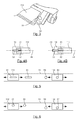
- it may be a draw bar as illustrated by the figure 3 and the Figures 4A and 4B .
- a first roller blind comprises a fabric 11, mounted on a roller tube 111, conventionally provided with return means (not shown) tending to return the fabric 11 in its folded position.
- the free end of the fabric 11 carries a guide bar 112, the two ends of which are guided in lateral rails 13 and 14, for example integral with the glazed roof.
- a second roller blind comprising a shade cloth 12 is mounted on a second roller tube 121, placed opposite the roller tube 111.
- the roller tube 111 can be placed on the rear side of the vehicle, and the retractor tube 121 on the front side of the vehicle.
- the second occulting fabric 12 is secured to a draw bar 122, also guided by the rails 13 and 14.
- the two blackout screens 11 and 12 can be made of the same material. According to a particular embodiment, the two canvases can also be different.
- the occultation screen 11 may be opaque, that is to say totally, or at the very least strongly occulting. It does not let any, or few, rays of sun.
- the second occultation fabric 12 may, however, be a perforated fabric capable of allowing a portion of the light to pass through.
- the two draw bars 112 and 122 are close to one another, and preferably secured to one another, substantially in the central position, that is to say substantially equidistant from the two tubes
- the rear part of the vehicle is obscured in a strong way, by the fabric 11, and the front part of the vehicle is obscured in an attenuated manner, using the perforated fabric 12.
- the length of the second fabric 12 wound on the winding tube 121 is sufficient for it to be deployed integrally, or almost completely, on the total surface to be obscured, as illustrated by FIG. Figure 2C .
- the two draw bars 112 and 122 which can remain secured to one another, are brought close to the winding tube 111.
- the entire glazed surface is attenuated , using the perforated canvas 12.
- the fabric 11 ensuring a strong or even total occultation, is fully deployed facing the surface to be obscured, the two pull bars 112 and 122 being brought close to the winding tube 121.
- the two draw bars 112 and 122 are in the central position, and it is desirable that they are immobilized, so that they do not move, depending on vibration, acceleration or braking of the vehicle.
- FIG. 3 provision is made to equip at least one end of the draw bar, and preferably both ends, of a movable movable finger 33, movable along or parallel to the main axis 44 ( Figures 4A and 4B ) of the pull bar 112, providing a blocking function in the central position ( Figure 2B ), in cooperation with a housing provided for this purpose in the guide rail.
- this approach can be implemented in the embodiment of the figure 1 , but also in a single-shade occultation device.
- the pull bar 112 and preferably also the other pull bar 122 are equipped with such fingers.
- the end of the draw bar 112 thus comprises in particular a guide shoe 32, sliding in a guide zone provided for this purpose in the rail 13, and the finger 33, forming a piston.
- two fingers are provided at each end of the draw bar, symmetrically.
- the implementation of the finger 33 is schematically illustrated by the Figures 4A and 4B .
- the finger 33 is mounted in a receptacle 42 of the pulling bar 112, which contains a return spring, tending to push the finger 33 outwards, that is towards the bottom of the rail 13.
- a housing 43 is formed in the bottom of the rail 13, adapted to receive the finger 33.
- the finger 33 passes at the housing 43, it enters the interior thereof, under the action of the spring 41.
- the draw bar 112 is then immobilized.
- the finger 33, the housing 43 and the spring 41 are dimensioned so as to ensure the locking of the draw bar, but also to allow a separation of the finger 33 and the housing 43 under the effect of sufficient traction (that is to say, greater than a predetermined threshold) so as to allow stall by passage of a hard point. In other words, it is not necessary to provide means for actuating the unlocking, the latter being obtained directly by acting on the draw bar.
- the dimensioning is also adapted, preferably, so that a rapid movement of a draw bar or two draw bars secured, for example to move from the position of the Figure 2C at the position of the 2D figure , does not cause an unwanted connection, in the intermediate position in the Figure 2B .
- the pin 33 is always in contact with the bottom of the rail 13, under the action of spring 41. This friction ensures a braking function, opposing a too rapid withdrawal of the fabric, under the action of the means of reminder of the roller tube. This is particularly useful at the moment when the user drops the draw bar after having unhooked it.
- the pull bar 112 carries a finger 52 of oblong shape, able to cooperate with an oblong slot 51.
- the pull bar 122 carries, meanwhile, a cylindrical section finger 54 cooperating with a cylindrical housing 53 .
- the finger 52 can not enter the housing 53 (the diameter of the finger being greater than the height of the housing), and that in the same way, the finger 54 can not enter the housing 51 (the length the finger being greater than the diameter of the housing). So we have two separate locking means, respectively for each of the draw bars, without the locking means of one of the draw bars interfering with the locking means of the other draw bars.
- the housings 56 and 57 formed in the rails 13 are preferably arranged on different wings of this rail, or on different areas.
- the housing 56 is offset in height, relative to the housing 58. It is therefore understood that the finger 55 can cooperate with the housing 56, but not with the housing 58, and that, conversely, the finger 57 can cooperate only with the housing 58.
- the two draw bars 112 and 122 are equipped with means for securing them to one another, for example in the form of an extension, or cap, of one of the draw bars, coming and clinging to the other draw bar. It is thus easy to simultaneously move the two draw bars, acting on one of them, to move from any of the positions of Figures 2B, 2C or 2D .
- This mechanism also allows easy separation of the two draw bars, for example by slightly raising the pull bar equipped with the cap, to fold one of the draw bars. It is possible in other positions than those illustrated in the Figures 2A to 2D only one of the two canvases 11 or 12 is deployed to the intermediate position. In this case corresponding pulling bar is maintained by means of the locking fingers and corresponding housings.
Applications Claiming Priority (1)
| Application Number | Priority Date | Filing Date | Title |
|---|---|---|---|
| FR1056076A FR2962940B1 (fr) | 2010-07-23 | 2010-07-23 | Dispositif d'occultation a pistons de blocage des barres de tirage |
Publications (1)
| Publication Number | Publication Date |
|---|---|
| EP2409866A1 true EP2409866A1 (de) | 2012-01-25 |
Family
ID=43629603
Family Applications (1)
| Application Number | Title | Priority Date | Filing Date |
|---|---|---|---|
| EP11174765A Withdrawn EP2409866A1 (de) | 2010-07-23 | 2011-07-20 | Abdeckvorrichtung mit Kolben zum Blockieren der Zugstangen |
Country Status (2)
| Country | Link |
|---|---|
| EP (1) | EP2409866A1 (de) |
| FR (1) | FR2962940B1 (de) |
Cited By (1)
| Publication number | Priority date | Publication date | Assignee | Title |
|---|---|---|---|---|
| CN113459780A (zh) * | 2021-07-19 | 2021-10-01 | 宁波昌扬机械工业有限公司 | 一种天窗遮阳帘拉杆 |
Citations (5)
| Publication number | Priority date | Publication date | Assignee | Title |
|---|---|---|---|---|
| EP0735229A1 (de) * | 1995-04-01 | 1996-10-02 | Polyplastic B.V. | Rollo |
| EP1112876A2 (de) * | 1999-12-27 | 2001-07-04 | Webasto Vehicle Systems International GmbH | Sonnenschutzvorrichtung für einen lichtdurchlässigen Fahrzeugdachbereich |
| EP1527925A1 (de) | 2003-11-03 | 2005-05-04 | Wagon Sas | Verdunkelungsvorrichtung für Kraftfahrzeugsglasoberfläche mit zwei Vorhänge und damit ausgerüstetes Fahrzeug |
| EP1547836A2 (de) * | 2003-12-26 | 2005-06-29 | Aisin Seiki Kabushiki Kaisha | Sonnenschutz für KFZ-Schiebedächer |
| EP2036771A1 (de) * | 2007-09-12 | 2009-03-18 | BOS GmbH & Co. KG | Schutzvorrichtung für einen Innenraum eines Kraftfahrzeugs und Führungsanordnung hierfür |
-
2010
- 2010-07-23 FR FR1056076A patent/FR2962940B1/fr not_active Expired - Fee Related
-
2011
- 2011-07-20 EP EP11174765A patent/EP2409866A1/de not_active Withdrawn
Patent Citations (5)
| Publication number | Priority date | Publication date | Assignee | Title |
|---|---|---|---|---|
| EP0735229A1 (de) * | 1995-04-01 | 1996-10-02 | Polyplastic B.V. | Rollo |
| EP1112876A2 (de) * | 1999-12-27 | 2001-07-04 | Webasto Vehicle Systems International GmbH | Sonnenschutzvorrichtung für einen lichtdurchlässigen Fahrzeugdachbereich |
| EP1527925A1 (de) | 2003-11-03 | 2005-05-04 | Wagon Sas | Verdunkelungsvorrichtung für Kraftfahrzeugsglasoberfläche mit zwei Vorhänge und damit ausgerüstetes Fahrzeug |
| EP1547836A2 (de) * | 2003-12-26 | 2005-06-29 | Aisin Seiki Kabushiki Kaisha | Sonnenschutz für KFZ-Schiebedächer |
| EP2036771A1 (de) * | 2007-09-12 | 2009-03-18 | BOS GmbH & Co. KG | Schutzvorrichtung für einen Innenraum eines Kraftfahrzeugs und Führungsanordnung hierfür |
Cited By (2)
| Publication number | Priority date | Publication date | Assignee | Title |
|---|---|---|---|---|
| CN113459780A (zh) * | 2021-07-19 | 2021-10-01 | 宁波昌扬机械工业有限公司 | 一种天窗遮阳帘拉杆 |
| CN113459780B (zh) * | 2021-07-19 | 2023-12-12 | 宁波昌扬机械工业有限公司 | 一种天窗遮阳帘拉杆 |
Also Published As
| Publication number | Publication date |
|---|---|
| FR2962940A1 (fr) | 2012-01-27 |
| FR2962940B1 (fr) | 2014-04-18 |
Similar Documents
| Publication | Publication Date | Title |
|---|---|---|
| EP2000340B1 (de) | Abdeckungsvorrichtung für Kraftfahrzeug mit über Kabel verbundenen Schwingarmen und entsprechendes Kraftfahrzeug | |
| EP1619078B1 (de) | Rollo für Laderaumabdeckung für ein Kraftfahrzeug und hiermit ausgestattetes Fahrzeug | |
| FR2882090A1 (fr) | Dispositif d'occultation a rideau enrouleur manuel et multi position | |
| FR2941735A1 (fr) | Dispositif d'occultation a opacite ajustable | |
| EP2409866A1 (de) | Abdeckvorrichtung mit Kolben zum Blockieren der Zugstangen | |
| EP1852309A1 (de) | Gepäckabdeckungsvorrichtung für Kraftfahrzeuge mit automatischer Teilöffnung und entsprechendes Kraftfahrzeug | |
| EP1527925B1 (de) | Verdunkelungsvorrichtung für Kraftfahrzeugsglasoberfläche mit zwei Vorhänge und damit ausgerüstetes Fahrzeug | |
| EP2017105B1 (de) | Abdeckungsrollo für Kraftfahrzeug mit Schwenkzugstange und entsprechendes Fahrzeug | |
| EP2143578B1 (de) | Rollo mit Blockierungsvorrichtung der Zugstange, und entsprechendes Kraftfahrzeug | |
| FR2934202A1 (fr) | Store a enrouleur pour vehicule automobile a moyens d'equilibrage de la barre de tirage, et vehicule automobile correspondant. | |
| EP1683666A2 (de) | Abschirmeinrichtung für ein Motorfahrzeug und korrespondierende Fahrzeuge | |
| EP1336519B1 (de) | Fensterrolle für Kraftfahrzeug mit Zugstange mit mobiler Abdeckung | |
| EP1852288B1 (de) | KFZ-Beschattungsvorrichtung mit klappbaren Spriegeln und dazugehöriges Fahrzeug | |
| EP2236730A2 (de) | Rollo-Kombination, insbesondere für Bullauge eines Luftfahrzeugs, die Mittel zur Aufrechterhaltung der Spannung umfasst | |
| FR2934203A1 (fr) | Store a enrouleur pour vehicule automobile a barre de tirage non perpendiculaire a l'axe de deplacement et vehicule correspondant. | |
| EP2080652B1 (de) | Abdeckvorrichtung mit Zugstange, die mit Ausgleichselementen ausgestattet ist, und entsprechendes Kraftfahrzeug | |
| FR2905723A1 (fr) | Dispositif d'occultation manuel et multi position. | |
| FR2931397A1 (fr) | Store pour partie superieure de vitre de portiere de vehicule automobile, et portiere correspondante | |
| FR2941736A1 (fr) | Dispositif d'occultation a reglages multiples | |
| FR2956361A1 (fr) | Dispositif d'occultation pour vehicule automobile et vehicule automobile correspondant | |
| EP2236729A2 (de) | Rollo-Kombination mit zwei Blenden insbesondere für Bullauge eines Luftfahrzeugs | |
| FR2833535A1 (fr) | Store a enrouleur, notamment pour vehicules automobiles, destine a occulter selectivement deux portions de surface vitree, portiere et vehicule correspondants | |
| FR2943715A1 (fr) | Ensemble de store notamment pour hublot d'aeronef, comprenant des moyens de maintien en tension | |
| FR2955803A1 (fr) | Dispositif d'occultation pour vehicule automobile, a actionnement deporte, et vehicule automobile correspondant. | |
| FR2907399A1 (fr) | Dispositif de separation a deploiement et maintien automatique,et vehicule automobile correspondant |
Legal Events
| Date | Code | Title | Description |
|---|---|---|---|
| AK | Designated contracting states |
Kind code of ref document: A1 Designated state(s): AL AT BE BG CH CY CZ DE DK EE ES FI FR GB GR HR HU IE IS IT LI LT LU LV MC MK MT NL NO PL PT RO RS SE SI SK SM TR |
|
| AX | Request for extension of the european patent |
Extension state: BA ME |
|
| PUAI | Public reference made under article 153(3) epc to a published international application that has entered the european phase |
Free format text: ORIGINAL CODE: 0009012 |
|
| 17P | Request for examination filed |
Effective date: 20120531 |
|
| 17Q | First examination report despatched |
Effective date: 20141210 |
|
| STAA | Information on the status of an ep patent application or granted ep patent |
Free format text: STATUS: THE APPLICATION IS DEEMED TO BE WITHDRAWN |
|
| 18D | Application deemed to be withdrawn |
Effective date: 20150421 |