EP2409824B1 - Vorrichtung und Verfahren zur energiesparenden Kalibrierung und Kühlung von Kunststoffprofilen - Google Patents
Vorrichtung und Verfahren zur energiesparenden Kalibrierung und Kühlung von Kunststoffprofilen Download PDFInfo
- Publication number
- EP2409824B1 EP2409824B1 EP11174798.6A EP11174798A EP2409824B1 EP 2409824 B1 EP2409824 B1 EP 2409824B1 EP 11174798 A EP11174798 A EP 11174798A EP 2409824 B1 EP2409824 B1 EP 2409824B1
- Authority
- EP
- European Patent Office
- Prior art keywords
- tank
- calibration
- cooling medium
- cooling
- calibration tank
- Prior art date
- Legal status (The legal status is an assumption and is not a legal conclusion. Google has not performed a legal analysis and makes no representation as to the accuracy of the status listed.)
- Not-in-force
Links
Images

Classifications
-
- B—PERFORMING OPERATIONS; TRANSPORTING
- B29—WORKING OF PLASTICS; WORKING OF SUBSTANCES IN A PLASTIC STATE IN GENERAL
- B29C—SHAPING OR JOINING OF PLASTICS; SHAPING OF MATERIAL IN A PLASTIC STATE, NOT OTHERWISE PROVIDED FOR; AFTER-TREATMENT OF THE SHAPED PRODUCTS, e.g. REPAIRING
- B29C48/00—Extrusion moulding, i.e. expressing the moulding material through a die or nozzle which imparts the desired form; Apparatus therefor
- B29C48/25—Component parts, details or accessories; Auxiliary operations
- B29C48/88—Thermal treatment of the stream of extruded material, e.g. cooling
- B29C48/90—Thermal treatment of the stream of extruded material, e.g. cooling with calibration or sizing, i.e. combined with fixing or setting of the final dimensions of the extruded article
- B29C48/905—Thermal treatment of the stream of extruded material, e.g. cooling with calibration or sizing, i.e. combined with fixing or setting of the final dimensions of the extruded article using wet calibration, i.e. in a quenching tank
-
- B—PERFORMING OPERATIONS; TRANSPORTING
- B29—WORKING OF PLASTICS; WORKING OF SUBSTANCES IN A PLASTIC STATE IN GENERAL
- B29C—SHAPING OR JOINING OF PLASTICS; SHAPING OF MATERIAL IN A PLASTIC STATE, NOT OTHERWISE PROVIDED FOR; AFTER-TREATMENT OF THE SHAPED PRODUCTS, e.g. REPAIRING
- B29C48/00—Extrusion moulding, i.e. expressing the moulding material through a die or nozzle which imparts the desired form; Apparatus therefor
- B29C48/03—Extrusion moulding, i.e. expressing the moulding material through a die or nozzle which imparts the desired form; Apparatus therefor characterised by the shape of the extruded material at extrusion
- B29C48/09—Articles with cross-sections having partially or fully enclosed cavities, e.g. pipes or channels
- B29C48/11—Articles with cross-sections having partially or fully enclosed cavities, e.g. pipes or channels comprising two or more partially or fully enclosed cavities, e.g. honeycomb-shaped
-
- B—PERFORMING OPERATIONS; TRANSPORTING
- B29—WORKING OF PLASTICS; WORKING OF SUBSTANCES IN A PLASTIC STATE IN GENERAL
- B29C—SHAPING OR JOINING OF PLASTICS; SHAPING OF MATERIAL IN A PLASTIC STATE, NOT OTHERWISE PROVIDED FOR; AFTER-TREATMENT OF THE SHAPED PRODUCTS, e.g. REPAIRING
- B29C48/00—Extrusion moulding, i.e. expressing the moulding material through a die or nozzle which imparts the desired form; Apparatus therefor
- B29C48/03—Extrusion moulding, i.e. expressing the moulding material through a die or nozzle which imparts the desired form; Apparatus therefor characterised by the shape of the extruded material at extrusion
- B29C48/12—Articles with an irregular circumference when viewed in cross-section, e.g. window profiles
-
- B—PERFORMING OPERATIONS; TRANSPORTING
- B29—WORKING OF PLASTICS; WORKING OF SUBSTANCES IN A PLASTIC STATE IN GENERAL
- B29C—SHAPING OR JOINING OF PLASTICS; SHAPING OF MATERIAL IN A PLASTIC STATE, NOT OTHERWISE PROVIDED FOR; AFTER-TREATMENT OF THE SHAPED PRODUCTS, e.g. REPAIRING
- B29C48/00—Extrusion moulding, i.e. expressing the moulding material through a die or nozzle which imparts the desired form; Apparatus therefor
- B29C48/25—Component parts, details or accessories; Auxiliary operations
- B29C48/92—Measuring, controlling or regulating
-
- B—PERFORMING OPERATIONS; TRANSPORTING
- B29—WORKING OF PLASTICS; WORKING OF SUBSTANCES IN A PLASTIC STATE IN GENERAL
- B29C—SHAPING OR JOINING OF PLASTICS; SHAPING OF MATERIAL IN A PLASTIC STATE, NOT OTHERWISE PROVIDED FOR; AFTER-TREATMENT OF THE SHAPED PRODUCTS, e.g. REPAIRING
- B29C2791/00—Shaping characteristics in general
- B29C2791/004—Shaping under special conditions
- B29C2791/006—Using vacuum
-
- B—PERFORMING OPERATIONS; TRANSPORTING
- B29—WORKING OF PLASTICS; WORKING OF SUBSTANCES IN A PLASTIC STATE IN GENERAL
- B29C—SHAPING OR JOINING OF PLASTICS; SHAPING OF MATERIAL IN A PLASTIC STATE, NOT OTHERWISE PROVIDED FOR; AFTER-TREATMENT OF THE SHAPED PRODUCTS, e.g. REPAIRING
- B29C2948/00—Indexing scheme relating to extrusion moulding
- B29C2948/92—Measuring, controlling or regulating
- B29C2948/92504—Controlled parameter
- B29C2948/92514—Pressure
-
- B—PERFORMING OPERATIONS; TRANSPORTING
- B29—WORKING OF PLASTICS; WORKING OF SUBSTANCES IN A PLASTIC STATE IN GENERAL
- B29C—SHAPING OR JOINING OF PLASTICS; SHAPING OF MATERIAL IN A PLASTIC STATE, NOT OTHERWISE PROVIDED FOR; AFTER-TREATMENT OF THE SHAPED PRODUCTS, e.g. REPAIRING
- B29C2948/00—Indexing scheme relating to extrusion moulding
- B29C2948/92—Measuring, controlling or regulating
- B29C2948/92819—Location or phase of control
- B29C2948/92923—Calibration, after-treatment or cooling zone
-
- B—PERFORMING OPERATIONS; TRANSPORTING
- B29—WORKING OF PLASTICS; WORKING OF SUBSTANCES IN A PLASTIC STATE IN GENERAL
- B29C—SHAPING OR JOINING OF PLASTICS; SHAPING OF MATERIAL IN A PLASTIC STATE, NOT OTHERWISE PROVIDED FOR; AFTER-TREATMENT OF THE SHAPED PRODUCTS, e.g. REPAIRING
- B29C48/00—Extrusion moulding, i.e. expressing the moulding material through a die or nozzle which imparts the desired form; Apparatus therefor
- B29C48/25—Component parts, details or accessories; Auxiliary operations
- B29C48/88—Thermal treatment of the stream of extruded material, e.g. cooling
- B29C48/90—Thermal treatment of the stream of extruded material, e.g. cooling with calibration or sizing, i.e. combined with fixing or setting of the final dimensions of the extruded article
- B29C48/901—Thermal treatment of the stream of extruded material, e.g. cooling with calibration or sizing, i.e. combined with fixing or setting of the final dimensions of the extruded article of hollow bodies
- B29C48/903—Thermal treatment of the stream of extruded material, e.g. cooling with calibration or sizing, i.e. combined with fixing or setting of the final dimensions of the extruded article of hollow bodies externally
-
- B—PERFORMING OPERATIONS; TRANSPORTING
- B29—WORKING OF PLASTICS; WORKING OF SUBSTANCES IN A PLASTIC STATE IN GENERAL
- B29C—SHAPING OR JOINING OF PLASTICS; SHAPING OF MATERIAL IN A PLASTIC STATE, NOT OTHERWISE PROVIDED FOR; AFTER-TREATMENT OF THE SHAPED PRODUCTS, e.g. REPAIRING
- B29C48/00—Extrusion moulding, i.e. expressing the moulding material through a die or nozzle which imparts the desired form; Apparatus therefor
- B29C48/25—Component parts, details or accessories; Auxiliary operations
- B29C48/88—Thermal treatment of the stream of extruded material, e.g. cooling
- B29C48/90—Thermal treatment of the stream of extruded material, e.g. cooling with calibration or sizing, i.e. combined with fixing or setting of the final dimensions of the extruded article
- B29C48/908—Thermal treatment of the stream of extruded material, e.g. cooling with calibration or sizing, i.e. combined with fixing or setting of the final dimensions of the extruded article characterised by calibrator surface, e.g. structure or holes for lubrication, cooling or venting
-
- B—PERFORMING OPERATIONS; TRANSPORTING
- B29—WORKING OF PLASTICS; WORKING OF SUBSTANCES IN A PLASTIC STATE IN GENERAL
- B29C—SHAPING OR JOINING OF PLASTICS; SHAPING OF MATERIAL IN A PLASTIC STATE, NOT OTHERWISE PROVIDED FOR; AFTER-TREATMENT OF THE SHAPED PRODUCTS, e.g. REPAIRING
- B29C48/00—Extrusion moulding, i.e. expressing the moulding material through a die or nozzle which imparts the desired form; Apparatus therefor
- B29C48/25—Component parts, details or accessories; Auxiliary operations
- B29C48/88—Thermal treatment of the stream of extruded material, e.g. cooling
- B29C48/911—Cooling
- B29C48/9115—Cooling of hollow articles
- B29C48/912—Cooling of hollow articles of tubular films
- B29C48/913—Cooling of hollow articles of tubular films externally
-
- B—PERFORMING OPERATIONS; TRANSPORTING
- B29—WORKING OF PLASTICS; WORKING OF SUBSTANCES IN A PLASTIC STATE IN GENERAL
- B29C—SHAPING OR JOINING OF PLASTICS; SHAPING OF MATERIAL IN A PLASTIC STATE, NOT OTHERWISE PROVIDED FOR; AFTER-TREATMENT OF THE SHAPED PRODUCTS, e.g. REPAIRING
- B29C48/00—Extrusion moulding, i.e. expressing the moulding material through a die or nozzle which imparts the desired form; Apparatus therefor
- B29C48/25—Component parts, details or accessories; Auxiliary operations
- B29C48/88—Thermal treatment of the stream of extruded material, e.g. cooling
- B29C48/919—Thermal treatment of the stream of extruded material, e.g. cooling using a bath, e.g. extruding into an open bath to coagulate or cool the material
-
- B—PERFORMING OPERATIONS; TRANSPORTING
- B29—WORKING OF PLASTICS; WORKING OF SUBSTANCES IN A PLASTIC STATE IN GENERAL
- B29L—INDEXING SCHEME ASSOCIATED WITH SUBCLASS B29C, RELATING TO PARTICULAR ARTICLES
- B29L2031/00—Other particular articles
- B29L2031/001—Profiled members, e.g. beams, sections
- B29L2031/003—Profiled members, e.g. beams, sections having a profiled transverse cross-section
Definitions
- the subject invention relates to a tank system for energy-saving calibration and cooling of plastic profiles, which are produced endlessly in the extrusion process according to the preamble of patent claim 1.
- Calibration tools for plastic profiles are used for defined cooling and shaping of the extruded profile formed in an extrusion die and comprise at least oneturikalibrierwerkmaschine and at least one calibration tank, which can also be placed under vacuum, and has a plurality of so-called Kalibrierblenden.
- the defined heat dissipation from the profile strand in the dry caliber by means of heat transfer from the tread surface to the cooled with cooling water inside surface of the dry caliber tool and in the calibration tank, the heat dissipation from the profile strand is done directly in the profile flow around the cooling medium (usually cooling water).
- Innkaliberwerkzeug the still soft profile strand is sucked by vacuum to the inner surface of the dry caliber tool, the inner surface is designed with the negative contour of the profile geometry, taking into account as complete contact of the profile contour with the negative contour, thus optimally and uniform heat transfer from the profile surface the dry caliber inner surface can be made.
- the cooling medium flows through the calibration tank in the longitudinal direction, thereby deprives the extruded profile, the remaining, introduced in the upstream extruder heat energy, and by means of a defined vacuum in the calibration tank, the shape changes due to shrinkage processes by cooling in profile counteracted.
- the prior art corresponds to calibration systems consisting of one or more dry calibers followed by one or more calibration tanks.
- These calibration tanks consist of a vacuum-tight tank, several support covers adapted to the shape of the profile, and end covers enclosing the profile at the two end faces.
- Cooling medium is supplied at one or more points in the calibration tank and preferably sucked off at one (or more) offset in the longitudinal direction arranged location (s) by means of negative pressure.
- the cooling medium is offset by targeted flow guidance in more or less highly developed turbulence, in order to increase the cooling effect.
- a calibration tank which consists of a tank and a plurality of tank panels that fill the cross-section of the tank and divide the tank lengthwise into several chambers, the tank panels are sealed against the tank. These tank panels have a first opening for the profile passage and at least one second opening for the passage of the cooling water. Via an inflow opening, the cooling water is passed into the tank in a first chamber and via a discharge opening in the last chamber, the cooling water is discharged.
- the negative pressure in the calibration tank is adjusted by means of a control valve (ball valve) by air supply.
- the cooling water is conveyed by means of negative pressure from one chamber to the next following chamber through the respective "second" opening in the tank covers and at the same time generates a turbulent flow.
- the disadvantage here is the high energy demand in the vacuum system due to fresh air supply to the vacuum regulation in the calibration tank, the restless flow of cooling media from one chamber to the next chamber and the relatively high flow of cooling medium at the same low cooling effect (temperature difference of the cooling water between inlet temperature and outlet temperature). Due to the flow forced by the differential pressure in the adjacent chambers, the negative pressure acting on the profile strand in each section of the calibration tank is different and flow-dependent, which leads to an additional impediment to process reliability.
- the enormous cooling water flow additionally requires a comparatively high proportion of energy for generating the flow and overcoming the flow resistance as a result of helical flow forms; the flow itself is created by differentiated pressure differences in adjacent chambers by means of vacuum. Again, it's up the profile line acting vacuum in each section of the calibration tank differently.
- a calibration device which consists of a tank under vacuum and a plurality of calibration orifices which fill the tank widthwise and have a height which allows a free flow of cooling water from one section to the next.
- cooling water is introduced from below via an inflow opening and in this way each individual section is flooded separately and the profile passed through preferably flows from bottom to top.
- the cooling water reaches a level just above the height of the tank panels and the cooling water flows in the last chamber from the penultimate chamber on the penultimate calibration diaphragm in the discharge chamber to a discharge opening and is sucked by means of this with negative pressure.
- a uniform negative pressure is generated by means of a separate air suction.
- the disadvantage here is the high cooling water consumption, because each chamber is supplied separately with cooling water.
- a calibration tank which consists of partially arranged in slotted pipes within the tank tank panels, is conveyed in the closed state of the tank from the gaps between the tank aperture and slot in the pipe cooling water transverse to the longitudinal direction of the profile strand. Cooling water and air are extracted via a single suction opening and the vacuum required for calibration is generated. Disadvantageous are the high water consumption and the indefinable vacuum level in the tank, because a control device required for this is missing and cooling water and air are sucked out via a single suction opening, which leads to enormous pressure fluctuations.
- a calibration device which consists of an outer airtight first tank and a second tank arranged therein, the height and width of which allow an overflow of cooling water from the second tank into the first tank.
- Tank panels are arranged in sections in the second tank and provided with an opening corresponding to the profile contour. Coolant is fed laterally from below into each individual section of the second tank, so that the cooling liquid flows around the profile strand from bottom to top and laterally flows over the second tank and flows into the first tank. From the first tank, the overflowing cooling liquid is sucked off and air is suctioned off via a separate suction opening and the vacuum level is regulated.
- the disadvantage is the high expenditure on equipment and the high water consumption, because each chamber is charged with cooling liquid, from.
- the pamphlets DE 196 22 419 C1 and EP 1 579 978 A1 reveal other calibration devices.
- the aim of the subject invention is to describe a calibration device with which the known disadvantages can be eliminated.
- the object of achieving a high cooling effect and a uniform, easily adjustable negative pressure within the calibration tank is achieved while at the same time the most economical use of energy is achieved by a system according to claim 1.
- downstream means in the given context on the side of the discharge opening for the cooling medium.
- the discharge opening is arranged below the overflow edge, whereby essentially the liquid level in the discharge chamber is determined. This feature of course relates to the position of use of the calibration tank in which the longitudinal axis of the calibration tank is horizontal.
- the function of the device according to the invention is significantly different from that of a conventional fluidized bath, in which the tank apertures complete the cross section of the calibration tank almost completely except for the opening for the passage of the profiled strand. Only through openings with a relatively small cross-section, the cooling medium is forcibly sucked through, causing corresponding turbulence.
- Such vortex baths have a high efficiency of cooling, but suffer from the disadvantage that it can very easily come to pulsating pressure fluctuations in the interior of the calibration tank, and also periodic fluctuations of the coolant level can be observed. These pressure fluctuations and level fluctuations can affect the quality of the manufactured extruded profile.
- the present invention is based on a different concept, namely that of a relatively quiet coolant flow, wherein the cooling effect is ensured by means of a corresponding volume flow.
- the quiet coolant flow is achieved through tank apertures that provide large flow cross-sections for the cooling medium by forming large area openings to both the sidewalls and the bottom of the calibration tank.
- a constant and uniform level of the cooling medium is achieved by the Matterströmbrende with its overflow edge, which defines the liquid level in the manner of a weir. It is essential that on the downstream side of the overflow, ie in the discharge chamber, a lower liquid level is set, which is defined by the discharge opening for the cooling medium.
- this lower level in the flue chamber is characterized adjusted that cooling medium is sucked through a pump with a relatively high flow rate through the discharge opening.
- the pump aspirates air, whereby a reduction of the power takes place.
- the liquid level in the discharge chamber can again rise slightly, so that an equilibrium state automatically sets. It has been found that this equilibrium position is relatively stable and, above all, no pressure fluctuations in the calibration tank are produced by this feedback process. In this way, a high quality of the profiles produced can be ensured.
- a uniform vacuum is generated via a suction opening, which is preferably provided in the region of the discharge chamber above the overflow edge.
- a suction opening which is preferably provided in the region of the discharge chamber above the overflow edge.
- the tank panels required for the calibration have a geometry which is specific to the calibration tank and allow free flow of the cooling medium along the profile string without a pressure difference being required to convey the cooling medium.
- the tank apertures height or width are compared to the inner dimensions of the calibration tank designed such that an unhindered pressure equalization over the entire length of the calibration tank is made possible and the cooling medium within the calibration tank laterally or above / below the tank aperture can flow freely.
- the calibration tank has at least one feed opening for the cooling medium and at least one outlet opening arranged offset in the longitudinal direction for the cooling medium. This discharge opening is located at one end of the calibration tank in a portion bounded by an overflow orifice.
- This Matterströmblende fills the entire inner width of the calibration tank and has a height that extends at least over the uppermost limit of the profile to be calibrated profile strand.
- the cooling medium is dammed up by means of the overflow and the inflowing cooling medium flows from the inflow freely along the profile strand on the upper edge of the overflow to the discharge opening, from which the cooling medium, preferably by means of negative pressure, conveyed away becomes. Separated from this outflow opening, air is sucked off via a second, separate opening, thus producing a uniform negative pressure in the calibration tank.
- a calibration tank system in which the cooling medium flow can be kept low because no functional flow is required for functional performance, and in which a uniform negative pressure throughout the calibration tank, because no pressure differences are required to promote the cooling medium, since no through The tank cross-section filling tank apertures partially defined chambers are present.
- the comparatively low cooling medium flow causes an increase in the temperature difference between cooling medium supply and cooling medium outflow, whereby an additional increase in efficiency is achieved.
- the present invention relates to a method using the above apparatus.
- Fig. 1 shows a calibration tank according to the invention in an isometric view in the open state.
- the extruded profile 1 produced endlessly in the extrusion process is conveyed in the extrusion direction 1 'through the calibration tank, consisting of the end faces 2, the side parts 3, the cover 4, the profile strand 1 being supported by the opening in the tank covers 5 adapted to the profile contour.
- At the two end faces 2 are end shields 6, which seal the calibration tank to the outside.
- cooling medium is conveyed via the feed opening 10 into the calibration tank and discharged via the outflow opening 8; Inside the calibration tank, a negative pressure is generated via the suction opening 9 for air.
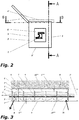
- Fig. 2 shows the calibration tank from the front, in which case the tank bottom 3 'can be seen.
- the fuel cap 4) is closed in the production state 4 'Halerept for the tank panels 5 are not shown for simplicity.
- Fig. 3 shows a longitudinal section (side view) of the calibration tank along the section line AA according to Fig. 2 ,
- the height of the cooling medium flow is determined by the height 7 "of the overflow 7, which has a distance 7 '" to the tank lid 4, to ensure a uniform negative pressure within the calibration tank.
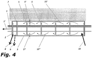
- Fig. 4 shows a longitudinal section (top view) of the calibration tank along the section line BB according to Fig. 2 ,
- the tank covers 5 have a distance 5 ', 5 "to the side walls 3 of the calibration tank, and the cooling medium can flow along the flow figures 10', 10" the tank panels 5.
- the overflow orifice 7 fills the entire width of the calibration tank and delimits the cooling medium flow with respect to the outflow opening 8. All tank panels 5 are fixed in not shown holding devices in the calibration tank.
Landscapes
- Engineering & Computer Science (AREA)
- Mechanical Engineering (AREA)
- Physics & Mathematics (AREA)
- Thermal Sciences (AREA)
- Extrusion Moulding Of Plastics Or The Like (AREA)
Description
- Die gegenständliche Erfindung bezieht auf ein Tanksystem zur energiesparenden Kalibrierung und Kühlung von Kunststoffprofilen, die endlos im Extrusionsverfahren hergestellt werden gemäß dem Oberbegriff von Patentanspruch 1.
- Kalibrierwerkzeuge für Kunststoffprofile dienen zum definierten Abkühlen und Formgeben des in einer Extrusionsdüse geformten Profilstranges und umfassen mindestens ein Trockenkalibrierwerkzeug und mindestens einen Kalibriertank, der ebenfalls unter Vakuum gesetzt werden kann, und mehrere sogenannten Kalibrierblenden aufweist. Dabei erfolgt die definierte Wärmeabfuhr aus dem Profilstrang im Trockenkaliber mittels Wärmeübertragung von der Profiloberfläche an die mit Kühlwasser gekühlte Innenfläche des Trockenkaliberwerkzeuges und im Kalibriertank erfolgt die Wärmeabfuhr aus dem Profilstrang direkt in das den Profilstrang umströmende Kühlmedium (üblicherweise Kühlwasser). Im Trockenkaliberwerkzeug wird der noch weiche Profilstrang mittels Vakuum an die Innenfläche des Trockenkaliberwerkzeuges angesaugt, wobei die Innenfläche mit der Negativkontur der Profilgeometrie ausgeführt ist, unter Berücksichtigung eines möglichst vollständigen Kontaktes der Profilkontur mit der Negativkontur, damit ein möglichst optimaler und gleichmäßiger Wärmeübergang von der Profiloberfläche an die Trockenkaliberinnenfläche erfolgen kann. Im Kalibriertank wird der Profilstrang in Stützblenden geführt und das Kühlmedium durchströmt in Längsrichtung den Kalibriertank, entzieht dabei dem Profilstrang die restliche, der im vorgelagerten Extruder eingebrachten Wärmeenergie, und mittels eines definierten Vakuums im Kalibriertank wird den Formänderungen infolge Schrumpfvorgängen durch Abkühlung im Profil entgegengewirkt.
- Dem Stand der Technik entsprechen Kalibriersysteme, bestehend aus einem oder mehreren Trockenkalibern gefolgt von einem oder mehreren Kalibriertanks. Diese Kalibriertanks bestehen aus einem vakuumdichten Tank, mehreren der Profilform angepasste Stützblenden und an den beiden Stirnseiten das Profil umschließende Abschlussblenden. Kühlmedium wird an einer oder mehreren Stellen im Kalibriertank zugeführt und vorzugsweise an einer (oder mehreren) in Längsrichtung versetzt angeordneten Stelle(n) mittels Unterdruck abgesaugt. Dabei wird das Kühlmedium durch gezielte Strömungsführung in mehr oder weniger stark ausgebildete Turbulenzen versetzt, zwecks Erhöhung der Kühlwirkung. Mittels einer separat vorgesehen Verbindung zu einem Vakuumsystem und spezieller regelbarer Luftventile wird ein definierter Unterdruck im Kalibriertank erzeugt, damit der über die Wasserströmung erzeugte Unterdruck für den erforderlichen Kühl- und Kalibrierprozess exakt nachjustiert werden kann. Nachteilig bei diesen Systemen ist der hohe Energiebedarf für die Förderung des Kühlmediums innerhalb des Kalibriertanks von einem Abschnitt zum nächsten mittels des Unterdruckes und der hohe Energieverlust infolge regelbarer Luftzufuhrventile.
- Aus der
EP 0 659 336 ist ein Kalibriertank bekannt, der aus einem Tank und mehreren Tankblenden besteht, die den Querschnitt des Tanks ausfüllen und den Tank der Länge nach in mehrere Kammern unterteilen, wobei die Tankblenden gegenüber dem Tank abgedichtet sind. Diese Tankblenden weisen eine erste Öffnung für die Profildurchführung und mindestens eine zweite Öffnung für das Durchströmen des Kühlwassers auf. Über eine Zuströmöffnung wird das Kühlwasser in den Tank in eine erste Kammer geleitet und über eine Abströmöffnung in der letzten Kammer wird das Kühlwasser abgefördert. Der Unterdruck im Kalibriertank wird mittels eines Regelventils (Kugelhahn) durch Luftzufuhr eingestellt. Das Kühlwasser wird mittels Unterdruck von einer Kammer zur nächstfolgenden Kammer durch die jeweils "zweite" Öffnung in den Tankblenden gefördert und gleichzeitig dabei eine turbulente Strömung erzeugt. Nachteilig dabei wirken sich der hohe Energiebedarf im Vakuumsystem infolge Frischluftzufuhr zur Unterdruckregulierung im Kalibriertank, die unruhige Kühlmedienströmung von einer Kammer zur nächstfolgenden Kammer und der verhältnismäßig hohe Kühlmedienfluss bei gleichzeitig geringem Kühleffekt (Temperaturdifferenz des Kühlwassers zwischen Zulauftemperatur und Abströmtemperatur) aus. Bedingt durch die mittels Differenzdruck in den benachbarten Kammern erzwungene Strömung ist der auf den Profilstrang einwirkende Unterdruck in jedem Abschnitt des Kalibriertanks unterschiedlich und strömungsabhängig, was zu einer zusätzlichen Erschwernis zur Prozesssicherheit führt. - Aus der
AT 409.738 - Aus der
AT 408.861 - Aus der
AT 007.670 - Aus der
AT 413.966 DE 196 22 419 C1 undEP 1 579 978 A1 offenbaren weitere Kalibriervorrichtungen. Ziel der gegenständlichen Erfindung ist es, eine Kalibriervorrichtung zu beschreiben, mit der die bekannten Nachteile beseitigt werden können. - Erfindungsgemäß wird die Aufgabe, eine hohe Kühlwirkung und einen innerhalb des Kalibriertanks gleichmäßigen, einfach einstellbaren Unterdruck zu erzeugen bei gleichzeitig sparsamstem Energieeinsatz durch ein System gemäß Patentanspruch 1 gelöst.
- Der Ausdruck stromabwärtig bedeutet im gegebenen Zusammenhang auf der Seite der Abströmöffnung für das Kühlmedium. Die Abströmöffnung ist unterhalb der Überströmkante angeordnet, wodurch im Wesentlichen der Flüssigkeitsspiegel in der Abzugskammer festgelegt wird. Dieses Merkmal bezieht sich selbstverständlich auf die Gebrauchslage des Kalibriertanks, in der die Längsachse des Kalibriertanks waagrecht ist.
- Die Funktion der erfindungsgemäßen Vorrichtung ist deutlich unterschiedlich zu der eines klassischen Wirbelbades, bei dem die Tankblenden abgesehen von der Öffnung für den Durchtritt des Profilstranges den Querschnitt des Kalibriertanks fast vollständig abschließen. Lediglich durch Öffnungen mit relativ geringem Querschnitt wird das Kühlmedium forciert durchgesaugt, wodurch entsprechende Verwirbelungen entstehen. Solche Wirbelbäder besitzen eine hohe Effizienz der Kühlung, leiden aber unter dem Nachteil, dass es sehr leicht zu pulsierenden Druckschwankungen im Inneren des Kalibriertanks kommen kann, wobei auch periodische Schwankungen des Kühlmittelspiegels zu beobachten sind. Diese Druckschwankungen und Niveauschwankungen können die Qualität des hergestellten Profilstranges beeinträchtigen.
- Die vorliegende Erfindung beruht auf einem unterschiedlichen Konzept, nämlich dem einer relativ ruhigen Kühlmittelströmung, wobei die Kühlwirkung über einen entsprechenden Volumenstrom sichergestellt wird. Der ruhige Kühlmittelstrom wird durch Tankblenden erreicht, die große Durchströmquerschnitte für das Kühlmedium bereitstellen, indem sie sowohl zu den Seitenwänden als auch zum Boden des Kalibriertanks großflächige Öffnungen bilden. Auch an der Oberseite der Tankblenden sind großzügige Überströmquerschnitte für die Luft vorgesehen. Ein konstantes und einheitliches Niveau des Kühlmediums wird durch die Überströmblende mit ihrer Überströmkante erreicht, die in der Art eines Wehrs den Flüssigkeitsspiegel festlegt. Wesentlich ist, dass an der stromabwärtigen Seite der Überströmblende, also in der Abzugskammer ein niedrigerer Flüssigkeitsspiegel eingestellt ist, der durch die Abströmöffnung für das Kühlmedium definiert ist. In einfacher Weise wird dieser niedrigere Spiegel in der Abzugskammer dadurch eingestellt, dass Kühlmedium über eine Pumpe mit relativ hoher Förderleistung über die Abströmöffnung abgesaugt wird. Wenn nun der Flüssigkeitsspiegel in der Abzugskammer das Niveau der Abströmöffnung erreicht, aspiriert die Pumpe Luft, wodurch eine Verringerung der Leistung stattfindet. Sobald auf diese Weise weniger Kühlmedium angesaugt wird, kann der Flüssigkeitsspiegel in der Abzugskammer wieder geringfügig ansteigen, so dass sich automatisch ein Gleichgewichtszustand einstellt. Es hat sich herausgestellt, dass diese Gleichgewichtslage relativ stabil ist und vor allem durch diesen Rückkoppelungsvorgang keine Druckschwankungen im Kalibriertank erzeugt werden. Auf diese Weise kann eine hohe Qualität der hergestellten Profile sichergestellt werden.
- In einer ersten bevorzugten Ausführungsvariante der Erfindung ist vorgesehen, dass im Kalibriertank ein einheitliches Vakuum über eine Absaugöffnung erzeugt wird, die vorzugsweise im Bereich der Abzugskammer oberhalb der Überströmkante vorgesehen ist. Auf diese Weise ist es möglich, das Vakuumniveau unabhängig vom Mengenstrom des Kühlmittels einzustellen, so dass eine besonders einfache Bedienung der Vorrichtung gegeben ist. Alternativ ist es allerdings auch möglich, dass die Luft gemeinsam mit dem Kühlmedium über die Abströmöffnung abgezogen wird, wobei gegebenenfalls das Vakuum durch gezielte Falschluftzufuhr in an sich bekannter Weise eingestellt werden kann.
- Ein wichtiger Aspekt ist, dass die zur Kalibrierung erforderlichen Tankblenden eine gegenüber dem Kalibriertank bestimmte Geometrie aufweisen, die ein freies Strömen des Kühlmediums entlang des Profilstranges erlauben, ohne dass zur Förderung des Kühlmediums eine Druckdifferenz erforderlich wäre. Dazu sind die Tankblenden der Höhe bzw. der Breite nach gegenüber den Innenabmessungen des Kalibriertanks derart gestaltet, dass ein ungehinderter Druckausgleich über der gesamten Länge des Kalibriertanks ermöglicht wird und das Kühlmedium innerhalb des Kalibriertanks seitlich bzw. oberhalb / unterhalb der Tankblende frei vorbeiströmen kann. Der Kalibriertank weist zumindest eine Zuführöffnung für das Kühlmedium und zumindest eine in Längsrichtung versetzt angeordnete Abströmöffnung für das Kühlmedium auf. Diese Abströmöffnung befindet sich an einem Ende des Kalibriertanks in einem Abschnitt, der von einer Überströmblende begrenzt ist. Diese Überströmblende füllt die gesamte Innenbreite des Kalibriertanks aus und weist eine Höhe auf, die zumindest über die oberste Begrenzung des zu kalibrierenden Profilstranges reicht. In dem von dieser Überströmblende begrenzten Abschnitt des Kalibriertanks befinden sich die zumindest eine Zuströmöffnung für das Kühlmedium und die einzelnen Tankblenden. Innerhalb dieses Abschnittes wird mittels der Überströmblende das Kühlmedium aufgestaut und das zuströmende Kühlmedium fließt von der Zuströmöffnung frei entlang des Profilstranges über die Oberkante der Überströmblende zur Abströmöffnung, von der das Kühlmedium, vorzugsweise mittels Unterdruck, abgefördert wird. Getrennt von dieser Abströmöffnung wird über eine zweite separate Öffnung Luft abgesaugt und derart ein einheitlicher Unterdruck im Kalibriertank erzeugt. Auf diese Weise wird ein Kalibriertanksystem gebildet, bei welchem der Kühlmedienfluss gering gehalten werden kann, weil zur Funktionserfüllung keine Zwangsströmung erforderlich ist, und bei welchem ein einheitlicher Unterdruck im gesamten Kalibriertank vorliegt, weil zur Förderung des Kühlmediums keine Druckdifferenzen erforderlich sind, da ja keine durch den Tankquerschnitt ausfüllende Tankblenden abschnittsweise abgegrenzte Kammern vorhanden sind. Die vergleichsweise geringe Kühlmedienströmung bewirkt eine Erhöhung der Temperaturdifferenz zwischen Kühlmedienzufuhr und Kühlmedienabströmung, wodurch eine zusätzliche Effizienzsteigerung erreicht wird.
- Weiters betrifft die vorliegende Erfindung ein Verfahren, bei dem die obige Vorrichtung verwendet wird.
- Die Erfindung wird anhand der
Figuren 1 bis 4 näher erläutert. Es zeigen: - Fig. 1
- eine schematische Darstellung des erfindungsgemäßen Kalibriertanks in einer axonometrischen Ansicht,
- Fig. 2
- einen Querschnitt des Kalibriertanks von
Fig. 1 , - Fig. 3
- einen Schnitt nach Linie A-A in
Fig. 2 und - Fig. 4
- einen Schnitt nach Linie B-B in
Fig. 2 . -
Fig. 1 zeigt einen erfindungsgemäßen Kalibriertank in isometrischer Darstellung in geöffnetem Zustand. Der endlos im Extrusionsverfahren erzeugte Profilstrang 1 wird in Extrusionsrichtung 1' durch den Kalibriertank, bestehend aus den Stirnseiten 2, den Seitenteilen 3, dem Deckel 4, gefördert, wobei der Profilstrang 1 durch die der Profilkontur angepasste Öffnung in den Tankblenden 5 gestützt wird. An den beiden Stirnseiten 2 befinden sich Endblenden 6, die den Kalibriertank nach außen hin abdichten. Im geschlossenen Zustand wird Kühlmedium über die Zuführöffnung 10 in den Kalibriertank gefördert und über die Abströmöffnung 8 abgeleitet; im Inneren des Kalibriertanks wird über die Absaugöffnung 9 für Luft ein Unterdruck erzeugt. -
Fig. 2 zeigt den Kalibriertank von der Stirnseite, wobei hier der Tankboden 3' zu sehen ist. Der Tankdeckel4) ist im Produktionszustand geschlossen 4' Halerungen für die Tankblenden 5 sind zur Vereinfachung nicht dargestellt. -
Fig. 3 zeigt einen Längsschnitt (Seitenansicht) des Kalibriertanks entlang der Schnittlinie A-A gemäßFig. 2 . Darin sind die Überströmblende 7, die Überströmkante 7', die Tankblenden 5, der Abstand 5'" der Tankblenden 5 zum Tankboden 3 und der Abstand 5"" der Tankblenden 5 zum Tankdeckel 4, die Kühlmedienzufuhr 10, die Kühlmedienströmung 10"" unterhalb der Tankblenden und die Kühlmedienströmung 10"' oberhalb des Profilstranges 1 sowie der Überlauf der Kühlmedienströmung 10"' über die Überströmkante 7' zur Abströmöffnung 8 dargestellt. Die Höhe der Kühlmedienströmung wird durch die Höhe 7" der Überströmblende 7 bestimmt, die einen Abstand 7'" zum Tankdeckel 4 aufweist, um einen einheitlichen Unterdruck innerhalb des Kalibriertanks zu gewährleisten. -
Fig. 4 zeigt einen Längsschnitt (Draufsicht) des Kalibriertanks entlang der Schnittlinie B-B gemäßFig. 2 . Die Tankblenden 5 weisen einen Abstand 5', 5" zu den Seitenwänden 3 des Kalibriertanks auf, und das Kühlmedium kann dabei entlang der Strömungsfiguren 10', 10" die Tankblenden 5 umströmen. Die Überströmblende 7 füllt die gesamte Breite des Kalibriertanks aus und grenzt die Kühlmedienströmung gegenüber der Abströmöffnung 8 ab. Sämtliche Tankblenden 5 sind in nicht näher dargestellten Haltevorrichtungen im Kalibriertank fixiert.
Claims (7)
- Vorrichtung zur energiesparenden Kalibrierung und Kühlung von extrudierten Profilsträngen (1) mit einem evakuierbaren Kalibriertank, in dem mehrere Tankblenden (5) angeordnet sind, durch die der zu kalibrierende Profilstrang (1) geführt wird, und die derart ausgeführt und angeordnet sind, dass eine freie Strömung des Kühlmediums entlang dem Profilstrang (1) von der Zuströmöffnung (10) bis zur Abströmöffnung (8) entsteht, wobei an der stromabwärtigen Seite des Kalibriertanks eine Überströmblende (7) vorgesehen ist, die unten und seitlich dicht am Kalibriertank anliegt und an ihrer Oberseite eine Überströmkante (7') aufweist, wobei die Überströmblende (7) einen Hauptabschnitt des Kalibriertanks an ihrer stromaufwärtigen Seite von einer Abzugskammer an ihrer stromabwärtigen Seite trennt, und wobei im Bereich der Abzugskammer eine Abströmöffnung (8) für das Kühlmedium unterhalb der Überströmkante (7') vorgesehen ist, dadurch gekennzeichnet, dass die
Tankblenden (5) beideseitig einen Abstand (5', 5") von Seitenwänden des Kalibriertanks und einen Abstand (5"') von einem Boden des Kalibriertanks aufweisen, so dass die Kühlmedienströmung (10', 10") die Tankblenden (5) seitlich und unten umströmt. - Vorrichtung nach Anspruch 1, dadurch gekennzeichnet, dass im Kalibriertank ein einheitliches Vakuum über eine Absaugöffnung (9) erzeugt wird, die vorzugsweise im Bereich der Abzugskammer oberhalb der Überströmkante (7') vorgesehen ist.
- Vorrichtung nach einem der Ansprüche 1 oder 2, dadurch gekennzeichnet, dass das Kühlmedium über die Abströmöffnung (8) und die Luft über die Luftabsaugöffnung (9) getrennt abgesaugt werden.
- Vorrichtung nach einem der Ansprüche 1 oder 2, dadurch gekennzeichnet, dass das Kühlmedium und die Luft gemeinsam abgesaugt werden.
- Verfahren zur energiesparenden Kalibrierung und Kühlung von extrudierten Profilsträngen (1), die durch den evakuierbaren Kalibriertank einer Vorrichtung nach dem Anspruch 1 geführt werden, in dem mehrere Tankblenden (5) angeordnet sind, durch die der zu kalibrierende Profilstrang (1) geführt wird, und wobei eine freie Strömung des Kühlmediums entlang dem Profilstrang (1) von der Zuströmöffnung (10) bis zur Abströmöffnung (8) herbeigeführt wird, wobei das Kühlmedium über eine Überströmkante (7') einer Überströmblende (7) von einem Hauptabschnitt des Kalibriertanks in eine Abzugskammer geführt wird und dort aus dem Kalibriertank angezogen wird, dadurch gekennzeichnet, dass das Kühlmedium die Tankblenden unten und seitlich umströmt.
- Verfahren nach Anspruch 5, dadurch gekennzeichnet, dass das Kühlmedium über die Abströmöffnung (8) und die Luft über die Luftabsaugöffnung (9) getrennt abgesaugt werden.
- Verfahren nach Anspruch 5, dadurch gekennzeichnet, dass das Kühlmedium und die Luft gemeinsam abgesaugt werden.
Applications Claiming Priority (1)
| Application Number | Priority Date | Filing Date | Title |
|---|---|---|---|
| ATA1231/2010A AT510731B1 (de) | 2010-07-22 | 2010-07-22 | Tanksystem zur energiesparenden kalibrierung und kühlung von kunststoffprofilen |
Publications (2)
| Publication Number | Publication Date |
|---|---|
| EP2409824A1 EP2409824A1 (de) | 2012-01-25 |
| EP2409824B1 true EP2409824B1 (de) | 2017-06-28 |
Family
ID=44763707
Family Applications (1)
| Application Number | Title | Priority Date | Filing Date |
|---|---|---|---|
| EP11174798.6A Not-in-force EP2409824B1 (de) | 2010-07-22 | 2011-07-21 | Vorrichtung und Verfahren zur energiesparenden Kalibrierung und Kühlung von Kunststoffprofilen |
Country Status (2)
| Country | Link |
|---|---|
| EP (1) | EP2409824B1 (de) |
| AT (1) | AT510731B1 (de) |
Citations (1)
| Publication number | Priority date | Publication date | Assignee | Title |
|---|---|---|---|---|
| EP1122050A2 (de) * | 2000-02-01 | 2001-08-08 | A + G Extrusion Technology GmbH | Vorrichtung zum kalibrierenden Abkühlen eines stranggepressten Kunststoffprofils |
Family Cites Families (9)
| Publication number | Priority date | Publication date | Assignee | Title |
|---|---|---|---|---|
| DE2239746A1 (de) * | 1972-08-12 | 1974-02-21 | Reifenhaeuser Kg | Vorrichtung zum kalibrieren von stranggepressten profilen, insbes. hohlprofilen, aus thermoplastischem kunststoff |
| NL9302212A (nl) | 1993-12-20 | 1995-07-17 | Spinder Stalinrichting Bv | Ligboxsamenstel voor grootvee. |
| ES2095737T3 (es) * | 1993-12-23 | 1997-02-16 | Technoplast Kunststofftechnik | Dispositivo para la refrigeracion de perfiles de plastico. |
| AT409738B (de) * | 1994-02-22 | 2002-10-25 | Greiner & Soehne C A | Kühl- und kalibriereinrichtung |
| DE19622419C2 (de) * | 1996-06-04 | 2000-09-14 | Koemmerling Kunststoff | Verfahren zum Kühlen, insbesondere Kalibrieren, von Kunststoffprofilen sowie Kalibriervorrichtung für eine Kunststoffextrusionsanlage |
| DE10109958C1 (de) * | 2001-03-01 | 2002-04-18 | Veka Ag | Gekühlte Kalibriervorrichtung für eine Kunststoffextrusionsanlage |
| DE102004015391B4 (de) * | 2004-03-26 | 2008-06-12 | Veka Ag | Vakuumkalibriervorrichtung |
| AT7670U1 (de) * | 2004-04-02 | 2005-07-25 | Coneco Extrusionstechnik Gmbh | Vorrichtung zum kühlen und kalibrieren eines extrudierten kunststoffprofils |
| AT413966B (de) * | 2004-08-26 | 2006-07-15 | Trinity Technology Gmbh | Kühlvorrichtung für strangpressprofile |
-
2010
- 2010-07-22 AT ATA1231/2010A patent/AT510731B1/de not_active IP Right Cessation
-
2011
- 2011-07-21 EP EP11174798.6A patent/EP2409824B1/de not_active Not-in-force
Patent Citations (1)
| Publication number | Priority date | Publication date | Assignee | Title |
|---|---|---|---|---|
| EP1122050A2 (de) * | 2000-02-01 | 2001-08-08 | A + G Extrusion Technology GmbH | Vorrichtung zum kalibrierenden Abkühlen eines stranggepressten Kunststoffprofils |
Also Published As
| Publication number | Publication date |
|---|---|
| AT510731B1 (de) | 2012-09-15 |
| EP2409824A1 (de) | 2012-01-25 |
| AT510731A1 (de) | 2012-06-15 |
Similar Documents
| Publication | Publication Date | Title |
|---|---|---|
| DE19504981B4 (de) | Kühl- und Kalibriereinrichtung für längliche Gegenstände aus Kunststoff | |
| AT516668B1 (de) | Vorrichtung und Verfahren zur Behandlung von flachem zu behandelndem Material | |
| EP3300486B1 (de) | Verfahren und vorrichtung zum kühlen von extrudierten profilen | |
| EP2952752B1 (de) | Umlenkbogen | |
| EP1122050B1 (de) | Vorrichtung zum kalibrierenden Abkühlen eines stranggepressten Kunststoffprofils | |
| DE3002578C2 (de) | Vorrichtung zum Entgasen einer Flüssigkeit | |
| DE19644253A1 (de) | Vorrichtung zum Behandeln von Substraten | |
| EP2842719A2 (de) | Verfahren und Vorrichtung zur Abkühlung von Kunststoffprofilen | |
| EP2409824B1 (de) | Vorrichtung und Verfahren zur energiesparenden Kalibrierung und Kühlung von Kunststoffprofilen | |
| EP3392215A1 (de) | Vorrichtung und verfahren zur kühlung eines mittels rohrziehen gefertigten glasstrangs | |
| EP2895312B1 (de) | Kalibrierungsvorrichtung und -verfahren für die profilextrusion | |
| AT509324B1 (de) | Rückschlagventil für kalibriertanks | |
| EP2185336B1 (de) | Kalibriervorrichtung mit Trockenkalibrierstrecke und Nasskalibrierstrecke und entsprechendes Kalibrierverfahren | |
| DE19549567B4 (de) | Kühl- und Kalibriereinrichtung für extrudierte Gegenstände sowie Verfahren zum Kühlen | |
| EP1558438B1 (de) | Vorrichtung zum kühlen und kalibrieren von kunststoffprofilen | |
| DE102016119219B3 (de) | Kühlaggregat | |
| DE102014015984A1 (de) | Thermisch geschichtete Beladung eines Fluidspeichers | |
| AT1888U1 (de) | Verfahren zum kühlen und gegebenenfalls kalibrieren von länglichen gegenständen aus kunststoff sowie kühl- und kalibriereinrichtung | |
| DE4109985C2 (de) | ||
| DE102017204492A1 (de) | Wärmetauscher für eine Schmelzflusselektrolysezelle | |
| AT409738B (de) | Kühl- und kalibriereinrichtung | |
| DE19745843A1 (de) | Kühleinrichtung sowie Verfahren zum Kühlen von extrudierten Gegenständen | |
| DE102011117463B3 (de) | Sandfang für Kläranlagen und Verfahren zum Betrieb eines derartigen Sandfangs | |
| AT16771U1 (de) | Randbeschickungsorgan für das bereitstellen von zusatzbeschickungsdurchfluss in einen turbulenzgenerator eines stoffauflaufs einer faserbahnmaschine | |
| DD225950B3 (de) | Vorrichtung zum Kühlen und Kalibrieren von extrudierten Kunststoffsträngen |
Legal Events
| Date | Code | Title | Description |
|---|---|---|---|
| AK | Designated contracting states |
Kind code of ref document: A1 Designated state(s): AL AT BE BG CH CY CZ DE DK EE ES FI FR GB GR HR HU IE IS IT LI LT LU LV MC MK MT NL NO PL PT RO RS SE SI SK SM TR |
|
| AX | Request for extension of the european patent |
Extension state: BA ME |
|
| PUAI | Public reference made under article 153(3) epc to a published international application that has entered the european phase |
Free format text: ORIGINAL CODE: 0009012 |
|
| 17P | Request for examination filed |
Effective date: 20120725 |
|
| RAP1 | Party data changed (applicant data changed or rights of an application transferred) |
Owner name: SMI SERVICE MANAGEMENT IMMOBILIEN GMBH |
|
| 17Q | First examination report despatched |
Effective date: 20140627 |
|
| GRAP | Despatch of communication of intention to grant a patent |
Free format text: ORIGINAL CODE: EPIDOSNIGR1 |
|
| RIC1 | Information provided on ipc code assigned before grant |
Ipc: B29C 47/90 20060101AFI20170307BHEP Ipc: B29C 47/92 20060101ALN20170307BHEP |
|
| INTG | Intention to grant announced |
Effective date: 20170320 |
|
| RIN1 | Information on inventor provided before grant (corrected) |
Inventor name: SCHWAIGER, MEINHARD |
|
| GRAS | Grant fee paid |
Free format text: ORIGINAL CODE: EPIDOSNIGR3 |
|
| GRAA | (expected) grant |
Free format text: ORIGINAL CODE: 0009210 |
|
| AK | Designated contracting states |
Kind code of ref document: B1 Designated state(s): AL AT BE BG CH CY CZ DE DK EE ES FI FR GB GR HR HU IE IS IT LI LT LU LV MC MK MT NL NO PL PT RO RS SE SI SK SM TR |
|
| REG | Reference to a national code |
Ref country code: GB Ref legal event code: FG4D Free format text: NOT ENGLISH |
|
| REG | Reference to a national code |
Ref country code: CH Ref legal event code: EP |
|
| REG | Reference to a national code |
Ref country code: AT Ref legal event code: REF Ref document number: 904454 Country of ref document: AT Kind code of ref document: T Effective date: 20170715 |
|
| REG | Reference to a national code |
Ref country code: IE Ref legal event code: FG4D Free format text: LANGUAGE OF EP DOCUMENT: GERMAN |
|
| REG | Reference to a national code |
Ref country code: DE Ref legal event code: R096 Ref document number: 502011012509 Country of ref document: DE |
|
| PG25 | Lapsed in a contracting state [announced via postgrant information from national office to epo] |
Ref country code: FI Free format text: LAPSE BECAUSE OF FAILURE TO SUBMIT A TRANSLATION OF THE DESCRIPTION OR TO PAY THE FEE WITHIN THE PRESCRIBED TIME-LIMIT Effective date: 20170628 Ref country code: GR Free format text: LAPSE BECAUSE OF FAILURE TO SUBMIT A TRANSLATION OF THE DESCRIPTION OR TO PAY THE FEE WITHIN THE PRESCRIBED TIME-LIMIT Effective date: 20170929 Ref country code: HR Free format text: LAPSE BECAUSE OF FAILURE TO SUBMIT A TRANSLATION OF THE DESCRIPTION OR TO PAY THE FEE WITHIN THE PRESCRIBED TIME-LIMIT Effective date: 20170628 Ref country code: NO Free format text: LAPSE BECAUSE OF FAILURE TO SUBMIT A TRANSLATION OF THE DESCRIPTION OR TO PAY THE FEE WITHIN THE PRESCRIBED TIME-LIMIT Effective date: 20170928 Ref country code: LT Free format text: LAPSE BECAUSE OF FAILURE TO SUBMIT A TRANSLATION OF THE DESCRIPTION OR TO PAY THE FEE WITHIN THE PRESCRIBED TIME-LIMIT Effective date: 20170628 |
|
| REG | Reference to a national code |
Ref country code: NL Ref legal event code: MP Effective date: 20170628 |
|
| REG | Reference to a national code |
Ref country code: LT Ref legal event code: MG4D |
|
| PG25 | Lapsed in a contracting state [announced via postgrant information from national office to epo] |
Ref country code: RS Free format text: LAPSE BECAUSE OF FAILURE TO SUBMIT A TRANSLATION OF THE DESCRIPTION OR TO PAY THE FEE WITHIN THE PRESCRIBED TIME-LIMIT Effective date: 20170628 Ref country code: BG Free format text: LAPSE BECAUSE OF FAILURE TO SUBMIT A TRANSLATION OF THE DESCRIPTION OR TO PAY THE FEE WITHIN THE PRESCRIBED TIME-LIMIT Effective date: 20170928 Ref country code: NL Free format text: LAPSE BECAUSE OF FAILURE TO SUBMIT A TRANSLATION OF THE DESCRIPTION OR TO PAY THE FEE WITHIN THE PRESCRIBED TIME-LIMIT Effective date: 20170628 Ref country code: SE Free format text: LAPSE BECAUSE OF FAILURE TO SUBMIT A TRANSLATION OF THE DESCRIPTION OR TO PAY THE FEE WITHIN THE PRESCRIBED TIME-LIMIT Effective date: 20170628 Ref country code: LV Free format text: LAPSE BECAUSE OF FAILURE TO SUBMIT A TRANSLATION OF THE DESCRIPTION OR TO PAY THE FEE WITHIN THE PRESCRIBED TIME-LIMIT Effective date: 20170628 |
|
| PG25 | Lapsed in a contracting state [announced via postgrant information from national office to epo] |
Ref country code: CZ Free format text: LAPSE BECAUSE OF FAILURE TO SUBMIT A TRANSLATION OF THE DESCRIPTION OR TO PAY THE FEE WITHIN THE PRESCRIBED TIME-LIMIT Effective date: 20170628 Ref country code: RO Free format text: LAPSE BECAUSE OF FAILURE TO SUBMIT A TRANSLATION OF THE DESCRIPTION OR TO PAY THE FEE WITHIN THE PRESCRIBED TIME-LIMIT Effective date: 20170628 Ref country code: EE Free format text: LAPSE BECAUSE OF FAILURE TO SUBMIT A TRANSLATION OF THE DESCRIPTION OR TO PAY THE FEE WITHIN THE PRESCRIBED TIME-LIMIT Effective date: 20170628 Ref country code: SK Free format text: LAPSE BECAUSE OF FAILURE TO SUBMIT A TRANSLATION OF THE DESCRIPTION OR TO PAY THE FEE WITHIN THE PRESCRIBED TIME-LIMIT Effective date: 20170628 |
|
| REG | Reference to a national code |
Ref country code: DE Ref legal event code: R119 Ref document number: 502011012509 Country of ref document: DE |
|
| PG25 | Lapsed in a contracting state [announced via postgrant information from national office to epo] |
Ref country code: SM Free format text: LAPSE BECAUSE OF FAILURE TO SUBMIT A TRANSLATION OF THE DESCRIPTION OR TO PAY THE FEE WITHIN THE PRESCRIBED TIME-LIMIT Effective date: 20170628 Ref country code: IS Free format text: LAPSE BECAUSE OF FAILURE TO SUBMIT A TRANSLATION OF THE DESCRIPTION OR TO PAY THE FEE WITHIN THE PRESCRIBED TIME-LIMIT Effective date: 20171028 Ref country code: PL Free format text: LAPSE BECAUSE OF FAILURE TO SUBMIT A TRANSLATION OF THE DESCRIPTION OR TO PAY THE FEE WITHIN THE PRESCRIBED TIME-LIMIT Effective date: 20170628 Ref country code: ES Free format text: LAPSE BECAUSE OF FAILURE TO SUBMIT A TRANSLATION OF THE DESCRIPTION OR TO PAY THE FEE WITHIN THE PRESCRIBED TIME-LIMIT Effective date: 20170628 Ref country code: IT Free format text: LAPSE BECAUSE OF FAILURE TO SUBMIT A TRANSLATION OF THE DESCRIPTION OR TO PAY THE FEE WITHIN THE PRESCRIBED TIME-LIMIT Effective date: 20170628 |
|
| REG | Reference to a national code |
Ref country code: CH Ref legal event code: PL |
|
| PG25 | Lapsed in a contracting state [announced via postgrant information from national office to epo] |
Ref country code: MC Free format text: LAPSE BECAUSE OF FAILURE TO SUBMIT A TRANSLATION OF THE DESCRIPTION OR TO PAY THE FEE WITHIN THE PRESCRIBED TIME-LIMIT Effective date: 20170628 |
|
| REG | Reference to a national code |
Ref country code: IE Ref legal event code: MM4A |
|
| PG25 | Lapsed in a contracting state [announced via postgrant information from national office to epo] |
Ref country code: DK Free format text: LAPSE BECAUSE OF FAILURE TO SUBMIT A TRANSLATION OF THE DESCRIPTION OR TO PAY THE FEE WITHIN THE PRESCRIBED TIME-LIMIT Effective date: 20170628 Ref country code: LI Free format text: LAPSE BECAUSE OF NON-PAYMENT OF DUE FEES Effective date: 20170731 Ref country code: CH Free format text: LAPSE BECAUSE OF NON-PAYMENT OF DUE FEES Effective date: 20170731 Ref country code: IE Free format text: LAPSE BECAUSE OF NON-PAYMENT OF DUE FEES Effective date: 20170721 Ref country code: DE Free format text: LAPSE BECAUSE OF NON-PAYMENT OF DUE FEES Effective date: 20180201 |
|
| PLBE | No opposition filed within time limit |
Free format text: ORIGINAL CODE: 0009261 |
|
| STAA | Information on the status of an ep patent application or granted ep patent |
Free format text: STATUS: NO OPPOSITION FILED WITHIN TIME LIMIT |
|
| GBPC | Gb: european patent ceased through non-payment of renewal fee |
Effective date: 20170928 |
|
| REG | Reference to a national code |
Ref country code: BE Ref legal event code: MM Effective date: 20170731 |
|
| 26N | No opposition filed |
Effective date: 20180329 |
|
| PG25 | Lapsed in a contracting state [announced via postgrant information from national office to epo] |
Ref country code: LU Free format text: LAPSE BECAUSE OF NON-PAYMENT OF DUE FEES Effective date: 20170721 |
|
| REG | Reference to a national code |
Ref country code: FR Ref legal event code: ST Effective date: 20180528 |
|
| PG25 | Lapsed in a contracting state [announced via postgrant information from national office to epo] |
Ref country code: GB Free format text: LAPSE BECAUSE OF NON-PAYMENT OF DUE FEES Effective date: 20170928 |
|
| PG25 | Lapsed in a contracting state [announced via postgrant information from national office to epo] |
Ref country code: SI Free format text: LAPSE BECAUSE OF FAILURE TO SUBMIT A TRANSLATION OF THE DESCRIPTION OR TO PAY THE FEE WITHIN THE PRESCRIBED TIME-LIMIT Effective date: 20170628 Ref country code: BE Free format text: LAPSE BECAUSE OF NON-PAYMENT OF DUE FEES Effective date: 20170731 Ref country code: FR Free format text: LAPSE BECAUSE OF NON-PAYMENT OF DUE FEES Effective date: 20170828 |
|
| REG | Reference to a national code |
Ref country code: AT Ref legal event code: MM01 Ref document number: 904454 Country of ref document: AT Kind code of ref document: T Effective date: 20170721 |
|
| PG25 | Lapsed in a contracting state [announced via postgrant information from national office to epo] |
Ref country code: MT Free format text: LAPSE BECAUSE OF FAILURE TO SUBMIT A TRANSLATION OF THE DESCRIPTION OR TO PAY THE FEE WITHIN THE PRESCRIBED TIME-LIMIT Effective date: 20170628 |
|
| PG25 | Lapsed in a contracting state [announced via postgrant information from national office to epo] |
Ref country code: AT Free format text: LAPSE BECAUSE OF NON-PAYMENT OF DUE FEES Effective date: 20170721 |
|
| PG25 | Lapsed in a contracting state [announced via postgrant information from national office to epo] |
Ref country code: HU Free format text: LAPSE BECAUSE OF FAILURE TO SUBMIT A TRANSLATION OF THE DESCRIPTION OR TO PAY THE FEE WITHIN THE PRESCRIBED TIME-LIMIT; INVALID AB INITIO Effective date: 20110721 |
|
| PG25 | Lapsed in a contracting state [announced via postgrant information from national office to epo] |
Ref country code: CY Free format text: LAPSE BECAUSE OF NON-PAYMENT OF DUE FEES Effective date: 20170628 |
|
| PG25 | Lapsed in a contracting state [announced via postgrant information from national office to epo] |
Ref country code: MK Free format text: LAPSE BECAUSE OF FAILURE TO SUBMIT A TRANSLATION OF THE DESCRIPTION OR TO PAY THE FEE WITHIN THE PRESCRIBED TIME-LIMIT Effective date: 20170628 |
|
| PG25 | Lapsed in a contracting state [announced via postgrant information from national office to epo] |
Ref country code: TR Free format text: LAPSE BECAUSE OF FAILURE TO SUBMIT A TRANSLATION OF THE DESCRIPTION OR TO PAY THE FEE WITHIN THE PRESCRIBED TIME-LIMIT Effective date: 20170628 |
|
| PG25 | Lapsed in a contracting state [announced via postgrant information from national office to epo] |
Ref country code: PT Free format text: LAPSE BECAUSE OF FAILURE TO SUBMIT A TRANSLATION OF THE DESCRIPTION OR TO PAY THE FEE WITHIN THE PRESCRIBED TIME-LIMIT Effective date: 20170628 |
|
| PG25 | Lapsed in a contracting state [announced via postgrant information from national office to epo] |
Ref country code: AL Free format text: LAPSE BECAUSE OF FAILURE TO SUBMIT A TRANSLATION OF THE DESCRIPTION OR TO PAY THE FEE WITHIN THE PRESCRIBED TIME-LIMIT Effective date: 20170628 |