EP2409785B1 - Singulator device for postal objects with anti-slide function - Google Patents
Singulator device for postal objects with anti-slide function Download PDFInfo
- Publication number
- EP2409785B1 EP2409785B1 EP10425245A EP10425245A EP2409785B1 EP 2409785 B1 EP2409785 B1 EP 2409785B1 EP 10425245 A EP10425245 A EP 10425245A EP 10425245 A EP10425245 A EP 10425245A EP 2409785 B1 EP2409785 B1 EP 2409785B1
- Authority
- EP
- European Patent Office
- Prior art keywords
- postal
- belts
- postal object
- withdrawing device
- motor
- Prior art date
- Legal status (The legal status is an assumption and is not a legal conclusion. Google has not performed a legal analysis and makes no representation as to the accuracy of the status listed.)
- Active
Links
- 230000000284 resting effect Effects 0.000 claims description 18
- 230000004913 activation Effects 0.000 claims description 10
- 229920001971 elastomer Polymers 0.000 claims description 3
- 230000002441 reversible effect Effects 0.000 claims description 3
- 229910000831 Steel Inorganic materials 0.000 claims description 2
- 230000003068 static effect Effects 0.000 claims description 2
- 239000010959 steel Substances 0.000 claims description 2
- 239000007769 metal material Substances 0.000 claims 1
- 230000004888 barrier function Effects 0.000 description 7
- 230000003287 optical effect Effects 0.000 description 7
- 230000001133 acceleration Effects 0.000 description 2
- 230000009471 action Effects 0.000 description 2
- 238000000034 method Methods 0.000 description 2
- 230000001960 triggered effect Effects 0.000 description 2
- 230000015572 biosynthetic process Effects 0.000 description 1
- 230000000903 blocking effect Effects 0.000 description 1
- 238000001514 detection method Methods 0.000 description 1
- 238000006073 displacement reaction Methods 0.000 description 1
- 230000000694 effects Effects 0.000 description 1
- 230000009931 harmful effect Effects 0.000 description 1
- 230000007246 mechanism Effects 0.000 description 1
- 229920003052 natural elastomer Polymers 0.000 description 1
- 229920001194 natural rubber Polymers 0.000 description 1
- 230000008569 process Effects 0.000 description 1
- 238000000926 separation method Methods 0.000 description 1
- 229920003051 synthetic elastomer Polymers 0.000 description 1
Images


Classifications
-
- B—PERFORMING OPERATIONS; TRANSPORTING
- B07—SEPARATING SOLIDS FROM SOLIDS; SORTING
- B07C—POSTAL SORTING; SORTING INDIVIDUAL ARTICLES, OR BULK MATERIAL FIT TO BE SORTED PIECE-MEAL, e.g. BY PICKING
- B07C1/00—Measures preceding sorting according to destination
- B07C1/02—Forming articles into a stream; Arranging articles in a stream, e.g. spacing, orientating
- B07C1/04—Forming a stream from a bulk; Controlling the stream, e.g. spacing the articles
-
- B—PERFORMING OPERATIONS; TRANSPORTING
- B65—CONVEYING; PACKING; STORING; HANDLING THIN OR FILAMENTARY MATERIAL
- B65H—HANDLING THIN OR FILAMENTARY MATERIAL, e.g. SHEETS, WEBS, CABLES
- B65H3/00—Separating articles from piles
- B65H3/02—Separating articles from piles using friction forces between articles and separator
- B65H3/04—Endless-belt separators
- B65H3/045—Endless-belt separators for separating substantially vertically stacked articles
-
- B—PERFORMING OPERATIONS; TRANSPORTING
- B65—CONVEYING; PACKING; STORING; HANDLING THIN OR FILAMENTARY MATERIAL
- B65H—HANDLING THIN OR FILAMENTARY MATERIAL, e.g. SHEETS, WEBS, CABLES
- B65H3/00—Separating articles from piles
- B65H3/46—Supplementary devices or measures to assist separation or prevent double feed
- B65H3/54—Pressing or holding devices
-
- B—PERFORMING OPERATIONS; TRANSPORTING
- B65—CONVEYING; PACKING; STORING; HANDLING THIN OR FILAMENTARY MATERIAL
- B65H—HANDLING THIN OR FILAMENTARY MATERIAL, e.g. SHEETS, WEBS, CABLES
- B65H2404/00—Parts for transporting or guiding the handled material
- B65H2404/20—Belts
- B65H2404/26—Particular arrangement of belt, or belts
- B65H2404/264—Arrangement of side-by-side belts
-
- B—PERFORMING OPERATIONS; TRANSPORTING
- B65—CONVEYING; PACKING; STORING; HANDLING THIN OR FILAMENTARY MATERIAL
- B65H—HANDLING THIN OR FILAMENTARY MATERIAL, e.g. SHEETS, WEBS, CABLES
- B65H2601/00—Problem to be solved or advantage achieved
- B65H2601/20—Avoiding or preventing undesirable effects
- B65H2601/25—Damages to handled material
-
- B—PERFORMING OPERATIONS; TRANSPORTING
- B65—CONVEYING; PACKING; STORING; HANDLING THIN OR FILAMENTARY MATERIAL
- B65H—HANDLING THIN OR FILAMENTARY MATERIAL, e.g. SHEETS, WEBS, CABLES
- B65H2701/00—Handled material; Storage means
- B65H2701/10—Handled articles or webs
- B65H2701/19—Specific article or web
- B65H2701/1916—Envelopes and articles of mail
Landscapes
- Engineering & Computer Science (AREA)
- Mechanical Engineering (AREA)
- Sheets, Magazines, And Separation Thereof (AREA)
- Delivering By Means Of Belts And Rollers (AREA)
Description
- The present invention relates to a singulator device for postal objects with anti-slide function.
- As is known, a singulator device receives at input groups of flat rectangular postal objects grouped together in packs and feeds at output singulated postal objects, i.e., postal objects physically separated from one another.
- For example, the documents Nos.
US-4,634,328 (Mail Singulation System),WO91/15416 US 4,171,130 (Control of withdrawal of flat items individually from a stack) andDE101 40 497 - Typically, the packs of postal objects, which have an approximately parallelepipedal shape, slide along a horizontal resting surface under the thrust of a drawing system that displaces the packs towards a singulator system designed to withdraw in sequence and individually the postal objects that form a front end face of the pack. Typically, the packs move in a rectilinear direction D of advance.
- The singulator system, for example, can comprise a motor-driven withdrawing belt, which forms a vertical plane gripping portion associated to a suction device; the postal object that forms the front face of the pack comes to bear upon the plane gripping portion that moves individually the postal object withdrawn in a direction L transverse to the direction of advance, separating it from the pack.
- The spatial separation between the postal objects singulated in sequence in the direction L is obtained by controlling the speed of the withdrawing belt and following with an optical barrier of emitter/receiver sensors the leading and trailing edges of each moving object in such a way that the trailing edge of one
postal object 7 is spaced in the direction L with respect to the leading edge of the object that follows it by a constant gap g. - The aim of said control is to create a flow of singulated postal objects separated from one another by a constant gap g, which moves at a controlled speed.
- An optical barrier of a known type comprises n emitter/receiver sensors C (C0, C1, C2, ....Cn) arranged aligned in a rectilinear direction parallel to the direction L, and the optical paths between emitters/receivers C (CO, C1, C2, ....Cn) are interrupted by the edges of the postal object that moves in the direction L. The sensor CO (first sensor) is closest to the withdrawal area, whereas the sensor Cn (last sensor) is furthest from the withdrawal area and located in a part of the conveying system where the speed of the objects in motion is constant and already equal to the steady running speed V.
- The process of withdrawal can comprise three steps, namely:
- step 1: waiting for obscuration of the last sensor Cn of the barrier. In this step, the motor-driven withdrawing belt moves with an acceleration ramp that is maintained until the last sensor Cn is obscured. Following upon obscuration of the last sensor Cn (the leading edge of the postal object has reached said sensor) the withdrawing belt is stopped with controlled deceleration ramp; the
postal object 7 now moves with practically constant speed V, its leading portion (edge) being already taken up by a pair of pinch rollers, which send it towards a conveying system set downstream, thus moving away from the pack of postal objects. The postal object subsequent to the one withdrawn, which forms the end face of the pack, is now stationary. All the sensors of the barrier have optical paths interrupted by the receding postal object or by the stationary postal object. - Step 2: Waiting for formation of a gap in the barrier. When the trailing edge of the receding postal object is physically separated from the leading edge of the stationary postal object, a gap is created, which enables passage of a signal between at least one emitter/receiver Ci (lighting-up of sensor Ci). The withdrawing belt is still kept stationary and computation of a time TCOR is triggered, which enables a recession of the trailing edge of the postal object that is moving with respect to the leading edge of the stationary postal object, which enables creation of a pre-set gap between the postal objects. The time TCOR is calculated on the basis of the position of the sensor Ci lit up and on the basis of the speedV of the receding postal object.
- Step 3: restart. Once the time TCOR has expired, the withdrawing belt is activated, and the operations previously described are repeated, thus creating a flow of postal objects separated from one another with a constant gap g.
- As mentioned above, in the course of the first step the postal object is conveyed (at constant speed V) by the pinch rollers, whilst the withdrawing belt is decelerated until it stops altogether; for this reason, a rear portion of the postal object slides on the stationary belt, which, as is known, has a high coefficient of friction (both static and dynamic).
- Sliding of the object on the belt can damage the postal object and/or can bring about opening of the postal object itself in the case where this is provided with closing flaps. These harmful effects are particularly evident in the case of longer formats, for example in the case of the well-known C4 format or above.
- Document
DE 101 40 497 describes a singulator as set in the preamble of claim 1. - The aim of the present invention is to provide a singulator device for postal objects that will solve the problems of the known art, preventing sliding of the rear portion of the postal object on the stationary belt.
- The above aim is achieved by the singulator device according to claim 1.
- The invention will now be illustrated with particular reference to the attached drawings, which illustrate a preferred non-limiting embodiment thereof and in which:
-
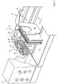
Figures 1 and2 illustrate, in front and rear perspective view, a singulator device built according to the present invention; -
Figure 3 illustrates, in perspective view, at an enlarged scale and partially in cross section, a singulator device built according to the present invention and set in a first operating position; -
Figure 4 illustrates, in perspective view, at an enlarged scale, and partially in cross section, a singulator device built according to the present invention and set in a second operating position; and -
Figure 5 illustrates operation of the device according to the invention. - In
Figures 1 and2 designated as a whole by 1 is a singulator device forpostal objects 7. - The
postal objects 7 of a flat type have a rectangular shape and are characterized by a major side L and by a minor side 1. The singulator device 1 is configured for receiving at input groups of flat rectangular postal objects grouped together in packs P (Figure 1 ) and feed at output singulatedpostal objects 7, i.e., postal objects physically separated from one another. - The device 1 comprises:
- a
singulator system 10; - a plane
rectangular resting wall 12 for the packs of postal objects, sliding on which is a motor-drivenplane belt 13; and - a drawing system 15 (built according to known techniques), which displaces the packs P along the
belt 13 parallel to a direction of advance D towards thesingulator system 10, which is set at one end of the planerectangular resting wall 12. - The
singulator system 10 is designed to withdraw individually the postal objects that form a front end face of the pack; in particular, as will be clarified hereinafter, thepostal object 7 forming the front face of the pack comes to bear upon a plane gripping portion 18 (Figure 2 ) of a motor-drivenbelt withdrawing device 19, which moves thepostal object 7 in a direction of unloading L transverse to the direction of advance D, separating it from the pack P. - The
drawing system 15 further comprises a slide 27 (represented partially), which slides under the thrust of a motor device (not illustrated) along arectilinear guide 26 parallel to the direction of advance D and carried by thewall 12. - The
slide 27 comprises a U-shaped plane pusher element (messer knife) 29 having plane of lie transverse to the direction of advance D and perpendicular to theresting wall 12 and to thebelt 13. - The
pusher element 29 is designed to come to bear upon a rear face of a pack P ofpostal objects 7 resting on the top surface of thebelt 13 for moving the front face of the pack P towards thesingulation system 10. - The device 1 comprises an electronic control unit C (illustrated schematically in
Figure 1 ) which controls, amongst other things, the motion of theslide 27 and of thepusher element 29, which move from a first end of the wall 12 (not illustrated) towards a second end of thewall 12 in the proximity of which thesingulation system 10 is located. In this way, the packs P of postal objects resting on theresting wall 12 are pushed by the pusher element (messer knife) 29 and by thebelt 13, which co-operates synchronously with the knife 29 (i.e., they are moved by the same mechanism), towards thesingulation system 10 and advance in the direction of advance D. - The motor-driven
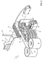
belt withdrawing device 19 extends between a pair of motor-drivenpulleys 30, which have axes perpendicular to thewall 12; in this way, the motor-drivenbelt withdrawing device 19 defines a pair of plane portions, one of which faces thepusher element 29 to provide theplane gripping portion 18. - In greater detail, the motor-driven
belt withdrawing device 19 comprises fourbelts pulleys 30 and each separated from the adjacent one/ones by a preset axial pitch P. Thebelts - In this way, between
adjacent belts 19a/19b, 19b/19c and 19c/19d arectangular window 32 opens. In particular - in the example of embodiment described - threerectangular windows 32 are present parallel to one another and arranged at different heights (Figures 1 and2 ). - Each withdrawing
belt holes 33, which communicate with a suction system S (of a known type - illustrated partially) set in the space delimited towards the outside by thebelts pulleys 30. - The
plane gripping portion 18 is then provided by a plane portion of thebelts wall 12; on theplane gripping portion 18 threerectangular windows 32 open. The direction of advance D is moreover perpendicular to the plane of theplane gripping portion 18. - An end postal object of the pack P comes into contact with the plane gripping portion of the
belts belts belt 19 enables displacement of the postal object attached to thebelts - The
postal object 7 slides along the unloading path until it sets itself between a pair of motor-drivenpinch rollers 35 set up against one another, which have axes perpendicular to thewall 12 and are designed to send the postal object (that sets itself between the two pinch rollers 35) towards a conveying system 36 of a known type that moves the postal object at a constant speed V. - The motor-driven
pinch rollers 35 are provided with an outer surface coated with rubber with a high coefficient of friction and turn at constant speed. The speed of rotation is very high, such as to guarantee on the tangent to the point of contact a speed of the postal object equal to the speed V of the conveying system 36. - According to the present invention, the motor-driven
belt withdrawing device 19 is coupled to aseparator device 40, which moves between at least two positions, of which: - a resting position (
Figure 3 ), in which theseparator device 40 does not interfere with thebelt withdrawing device 19 and with the postal object during withdrawal from the pack by the withdrawingdevice 19; and - an activation position (
Figure 4 ), in which the separator device has a mobile portion that extends beyond the plane gripping portion towards the pack of objects and comes into contact with a rear portion of the postal object during withdrawal, moving it away from thebelt withdrawing device 19. - In particular, the mobile portion of the separator device, in the example of embodiment illustrated, comprises three
elongated bars 42, each of which is housed - in the resting position - in the space delimited betweenadjacent belts 19a/19b, 19b/19c, and 19c/19d and does not project beyond the gripping surface. Thebars 42 are rectilinear, parallel to one another and have a preferably circular cross section. Preferably, thebars 42 are made of steel having minimum coefficient of dynamic friction, in the region of 0.05-0.25. - The
bars 42 are designed to set themselves - in the activation position - in a plane parallel to that of the plane gripping portion, projecting towards the outside of thebelts respective windows 32. - The reversible motion of the
bars 42 from the resting position to the activation position (and vice versa) through thewindows 32 occurs under the thrust of an electromagnetic actuator 45 (Figure 2 ) controlled by the electronic unit and having an output member (not illustrated) that is linearly mobile with reversible motion and supports thebars 42. - A barrier of n emitter/receiver sensors C (CO, C1, C2, ....Cn - not illustrated for simplicity) is set aligned in a rectilinear direction parallel to the direction L, and the optical paths between emitters and receivers C (C0, C1, C2, ....Cn) are interrupted by the edges of the postal object that moves in the direction L. The sensor CO (first sensor) is closest to the withdrawal area, whereas the sensor Cn (last sensor) is furthest from the withdrawal area and positioned slightly downstream with respect to the point of tangency of the
pinch rollers 35. - The various operations of the device 1 carried out under the control of the electronic unit are illustrated with the aid of the flowchart of
Figure 5 . - Initially, with the postal object already accelerated by the withdrawing belt at the speed V, in block 100 a check is made to verify whether the last sensor Cn has detected the presence of a
postal object 7. The detection typically occurs following upon interruption of the optical path existing between emitter and receiver of the sensor Cn. - If the presence is not detected, block 100 is followed by a
block 110 that keeps in rotation thebelts block 110 the flow returns to block 100. In this step, theseparator device 40 is set in a resting position. - In this way, the motor-driven
belts - Otherwise (i.e., if the last sensor Cn has detected the presence of a
postal object 7 in so far as the postal object has moved away from the pack following upon its withdrawal) block 100 is followed both by ablock 120, in which a command is issued for blocking thebelts block 125, in which a command is issued for activation of the anti-slide device. - In this way, following upon obscuration of the last sensor Cn, the withdrawing belt is stopped with a controlled deceleration ramp; the
postal object 7 previously withdrawn from the pack moves at constant speed V drawn by the pair ofpinch rollers 35, which send it towards the conveying system 34. The postal object subsequent to the one withdrawn, which forms now the end face of the pack, is stationary. All the sensors of the first and second barriers have optical paths interrupted by the receding postal object or by the stationary postal object. - In addition, setting of the
separator device 40 in the activation position brings about recession of the trailing edge of thepostal object 7 from thebelts block 125, controlled practically together with operation ofblock 120, is activated when the leading edge of thepostal object 7 is gripped between thepinch rollers 35 to prevent the trailing edge of the postal object withdrawn by thepinch rollers 35 from sliding on thebelts -
Blocks block 130, where the control unit sets itself waiting for the following logic condition: - at least one first sensor Ci detects the absence of a postal object.
- Said condition corresponds to the creation of a gap between the trailing edge of the receding postal object and the leading edge of the stationary postal object.
- In other words, a gap is created, which enables passage of a signal between at least one emitter and at least one receiver of the sensor Ci.
-
Block 130 is followed by ablock 135, in which a command is issued for return of the anti-slide device into a resting position in order to enable gripping by thebelts bars 42 in the extracted position -device 40 activated - would not enable gripping by the belts on the postal object). - The withdrawing belt is still kept stationary, and there is moreover triggered (block 140 parallel to block 135) computation of a correction time TCOR (by means of algorithms known and hence not illustrated - the correction time TCOR is calculated on the basis of the position of the sensor lit up Ci and on the basis of the speed V of the receding postal object), said correction time TCOR enabling a recession of the trailing edge of the postal object that is moving with respect to the leading edge of the stationary postal object, which enables creation of a pre-set gap between the postal objects being separated.
- From
block 160 the flow returns to block 100, and thebelts - In this way, the operations previously described are repeated, thus creating a flow of postal objects separated from one another with a constant gap g without the rear portion of the receding postal object possibly sliding on the motor-driven
belt withdrawing device 19. - Added to the advantages of the present invention is the possibility of processing particular postal objects such as, for example, folded newspapers with a transverse paper band. The effect of the
anti-slide device 42 is also to prevent sliding-off of the paper band from the newspaper precisely because sliding of the band on the belts is prevented during deceleration or when the belts are stationary.
Claims (7)
- A singulator device for flat rectangular postal objects, comprising:- a resting surface (12,13) for the packs of postal objects;- a motor-driven belt withdrawing device (19); and- a drawing system (15), which displaces the packs towards a plane gripping portion of said motor-driven belt withdrawing device (19) designed to withdraw individually a postal object that constitutes a front end face of the pack, displacing it in a direction transverse to the direction of drawing and loosening it from the pack,said motor-driven belt withdrawing device (19) is coupled to a separator device (40), which moves between at least two positions, of which:- a resting position, in which the separator device (40) does not interfere with the belt withdrawing device (19) and with the postal object during withdrawal from the pack by the withdrawing device (19); and- an activation position, in which a mobile portion of the withdrawing device extends beyond the plane gripping portion towards the pack of objects to come into contact with a rear portion of the postal object during withdrawal, moving it away from the belt withdrawing device (19) and preventing sliding of the rear portion on the belt or sliding-off of a band for closing the postal object, in particular a newspaper,characterized in that said motor-driven belt withdrawing device (19) comprises at least one pair of adjacent belts carried by end pulleys (30) and separated axially, with respect to one another, by a pre-set axial pitch (P) for defining an elongated window that opens between the two adjacent belts;
said mobile portion of the separator device comprising an elongate element (42) which is housed - in the resting
position - in the space delimited between adjacent belts (19a/19b, 19b/19c and 19c/19d) and does not project beyond the surface of the plane gripping portion;
said elongated element (42) is designed to set itself - in the activation position - in a plane parallel to that of the plane gripping portion, projecting towards the outside of the belts (19a, 19b, 19c and 19d) after having traversed the respective window (32). - The device according to Claim 1, wherein said elongated element is a bar that has a substantially circular cross section.
- The device according to Claim 1 or Claim 2, wherein said elongated element is made of metal material, preferably steel, and has a coefficient of dynamic and static friction decidedly lower than the coefficient of friction of the rubber of the belts (19a, 19b, 19c and 19d).
- The device according to any of the preeceding claims wherein said elongated element has a coefficient of friction in the region of 0.05-0.25.
- The device according to Claim 1, wherein the motor-driven belt withdrawing device (19) comprises four belts (19a, 19b, 19c and 19d) separated from one another, carried by end pulleys (30) and each set at a distance from the adjacent one/ones by a preset axial pitch (P); pairs of adjacent belts (19a/19b, 19b/19c and 19c/19d) delimiting major sides of three rectangular windows (32) parallel to one another and arranged at different heights;
the mobile portion of said separator device comprising three elongated bars (42), each of which is housed - in the resting position - in the space delimited between adjacent belts (19a/19b, 19b/19c and 19c/19d) and does not project beyond the gripping surface;
said bars (42) are designed to set themselves - in the activation position - in a plane parallel to that of the plane gripping portion projecting towards the outside of the belts (19a, 19b, 19c and 19d) after having traversed the respective windows (32);
the separator device comprising an electromagnetic actuator (45) having an output member that is linearly mobile with reversible motion and supports the bars (42). - The device according to Claim 1, wherein control means are provided, designed to govern arrangement (125) of said belt withdrawing device between the resting position and the activation position when a leading edge of the receding postal object reaches a pre-set position with respect to the motor-driven belt withdrawing device.
- The device according to Claim 1, wherein control means are provided, designed to govern arrangement of said belt withdrawing device from the resting position to the activation position when a leading edge of the postal object is inserted between a pair of pinch-rollers, which are designed to send the postal object towards a conveying system.
Priority Applications (2)
| Application Number | Priority Date | Filing Date | Title |
|---|---|---|---|
| EP10425245A EP2409785B1 (en) | 2010-07-21 | 2010-07-21 | Singulator device for postal objects with anti-slide function |
| PL10425245T PL2409785T3 (en) | 2010-07-21 | 2010-07-21 | Singulator device for postal objects with anti-slide function |
Applications Claiming Priority (1)
| Application Number | Priority Date | Filing Date | Title |
|---|---|---|---|
| EP10425245A EP2409785B1 (en) | 2010-07-21 | 2010-07-21 | Singulator device for postal objects with anti-slide function |
Publications (2)
| Publication Number | Publication Date |
|---|---|
| EP2409785A1 EP2409785A1 (en) | 2012-01-25 |
| EP2409785B1 true EP2409785B1 (en) | 2013-01-16 |
Family
ID=43416300
Family Applications (1)
| Application Number | Title | Priority Date | Filing Date |
|---|---|---|---|
| EP10425245A Active EP2409785B1 (en) | 2010-07-21 | 2010-07-21 | Singulator device for postal objects with anti-slide function |
Country Status (2)
| Country | Link |
|---|---|
| EP (1) | EP2409785B1 (en) |
| PL (1) | PL2409785T3 (en) |
Families Citing this family (1)
| Publication number | Priority date | Publication date | Assignee | Title |
|---|---|---|---|---|
| CN109552872B (en) * | 2018-12-19 | 2020-07-14 | 昆山艾博机器人技术有限公司 | Automatic sheet surface material feeding device |
Family Cites Families (6)
| Publication number | Priority date | Publication date | Assignee | Title |
|---|---|---|---|---|
| DE2758007C2 (en) | 1977-12-24 | 1979-10-25 | Licentia Patent-Verwaltungs-Gmbh, 6000 Frankfurt | Method for controlling the withdrawal process in a device for the delivery of isolated mail items of different lengths and a corresponding device |
| US4634328A (en) | 1985-05-31 | 1987-01-06 | Rca Corporation | Mail singulation system |
| WO1991015416A1 (en) | 1990-04-07 | 1991-10-17 | David Sarnoff Research Center, Inc. | Flats mail singulation apparatus |
| AU7460996A (en) * | 1996-10-18 | 1998-05-15 | Bell & Howell Postal Systems Inc | Pivotal tray unloading apparatus |
| DE10140497C1 (en) | 2001-08-17 | 2003-03-13 | Siemens Dematic Ag | Separation device for mail sorting installation with operation of driven extraction device in reverse direction for returning letter upon failed separation |
| US6679491B2 (en) * | 2001-09-17 | 2004-01-20 | Siemens Aktiengesellschaft | Mail piece feeder control system and method |
-
2010
- 2010-07-21 EP EP10425245A patent/EP2409785B1/en active Active
- 2010-07-21 PL PL10425245T patent/PL2409785T3/en unknown
Also Published As
| Publication number | Publication date |
|---|---|
| PL2409785T3 (en) | 2013-10-31 |
| EP2409785A1 (en) | 2012-01-25 |
Similar Documents
| Publication | Publication Date | Title |
|---|---|---|
| US8235377B2 (en) | Multi-mode unstacker device for unstacking mailpieces | |
| US8540235B2 (en) | Conveying apparatus for envelopes and related methods | |
| EP3326945B1 (en) | Sheet cutting device | |
| EP2151404A2 (en) | Improved Pickoff Mechanism for Mail Feeder | |
| US20210284473A1 (en) | Method and apparatus for processing envelopes containing contents | |
| KR20060111477A (en) | Device for singulating overlapping flat mailings | |
| EP2409785B1 (en) | Singulator device for postal objects with anti-slide function | |
| EP1927563B1 (en) | Method and apparatus for enhanced cutter throughput using an exit motion profile | |
| US20130237397A1 (en) | Device and method for buffering a plurality of goods or groups of goods and paper handling system comprising same | |
| KR100246834B1 (en) | Device for turning the front panel of a plate-like workpiece within a folder-gluer | |
| EP1798176B1 (en) | Cutter sequencing method and apparatus | |
| US9126348B2 (en) | Method for regulating the speed of a cutting device | |
| EP3059192B1 (en) | Envelope feeder with selective suction cup assist | |
| EP2409786B1 (en) | Singulator device for postal objects coated with transparent film | |
| EP2824051B1 (en) | Sheet folding device | |
| JP6207853B2 (en) | Paper sheet processing equipment | |
| EP2660073B1 (en) | Method for adjusting at least one means of an inserting apparatus and inserting apparatus | |
| AU2015264954A1 (en) | Method and apparatus for processing envelopes containing contents |
Legal Events
| Date | Code | Title | Description |
|---|---|---|---|
| AK | Designated contracting states |
Kind code of ref document: A1 Designated state(s): AL AT BE BG CH CY CZ DE DK EE ES FI FR GB GR HR HU IE IS IT LI LT LU LV MC MK MT NL NO PL PT RO SE SI SK SM TR |
|
| AX | Request for extension of the european patent |
Extension state: BA ME RS |
|
| PUAI | Public reference made under article 153(3) epc to a published international application that has entered the european phase |
Free format text: ORIGINAL CODE: 0009012 |
|
| 17P | Request for examination filed |
Effective date: 20120412 |
|
| RIC1 | Information provided on ipc code assigned before grant |
Ipc: B65H 3/04 20060101ALI20120507BHEP Ipc: B07C 1/04 20060101AFI20120507BHEP |
|
| GRAP | Despatch of communication of intention to grant a patent |
Free format text: ORIGINAL CODE: EPIDOSNIGR1 |
|
| GRAS | Grant fee paid |
Free format text: ORIGINAL CODE: EPIDOSNIGR3 |
|
| GRAA | (expected) grant |
Free format text: ORIGINAL CODE: 0009210 |
|
| RAP1 | Party data changed (applicant data changed or rights of an application transferred) |
Owner name: SELEX ELSAG S.P.A. |
|
| AK | Designated contracting states |
Kind code of ref document: B1 Designated state(s): AL AT BE BG CH CY CZ DE DK EE ES FI FR GB GR HR HU IE IS IT LI LT LU LV MC MK MT NL NO PL PT RO SE SI SK SM TR |
|
| REG | Reference to a national code |
Ref country code: GB Ref legal event code: FG4D |
|
| REG | Reference to a national code |
Ref country code: CH Ref legal event code: EP |
|
| REG | Reference to a national code |
Ref country code: IE Ref legal event code: FG4D |
|
| REG | Reference to a national code |
Ref country code: AT Ref legal event code: REF Ref document number: 593579 Country of ref document: AT Kind code of ref document: T Effective date: 20130215 Ref country code: CH Ref legal event code: EP |
|
| REG | Reference to a national code |
Ref country code: DE Ref legal event code: R096 Ref document number: 602010004657 Country of ref document: DE Effective date: 20130307 |
|
| RAP2 | Party data changed (patent owner data changed or rights of a patent transferred) |
Owner name: SELEX ES S.P.A. |
|
| REG | Reference to a national code |
Ref country code: AT Ref legal event code: MK05 Ref document number: 593579 Country of ref document: AT Kind code of ref document: T Effective date: 20130116 |
|
| REG | Reference to a national code |
Ref country code: NL Ref legal event code: VDEP Effective date: 20130116 |
|
| REG | Reference to a national code |
Ref country code: LT Ref legal event code: MG4D |
|
| REG | Reference to a national code |
Ref country code: DE Ref legal event code: R081 Ref document number: 602010004657 Country of ref document: DE Owner name: SELEX ES S.P.A., IT Free format text: FORMER OWNER: SELEX ELSAG S.P.A., GENOVA, IT Effective date: 20130521 |
|
| PG25 | Lapsed in a contracting state [announced via postgrant information from national office to epo] |
Ref country code: IS Free format text: LAPSE BECAUSE OF FAILURE TO SUBMIT A TRANSLATION OF THE DESCRIPTION OR TO PAY THE FEE WITHIN THE PRESCRIBED TIME-LIMIT Effective date: 20130516 Ref country code: LT Free format text: LAPSE BECAUSE OF FAILURE TO SUBMIT A TRANSLATION OF THE DESCRIPTION OR TO PAY THE FEE WITHIN THE PRESCRIBED TIME-LIMIT Effective date: 20130116 Ref country code: BG Free format text: LAPSE BECAUSE OF FAILURE TO SUBMIT A TRANSLATION OF THE DESCRIPTION OR TO PAY THE FEE WITHIN THE PRESCRIBED TIME-LIMIT Effective date: 20130416 Ref country code: AT Free format text: LAPSE BECAUSE OF FAILURE TO SUBMIT A TRANSLATION OF THE DESCRIPTION OR TO PAY THE FEE WITHIN THE PRESCRIBED TIME-LIMIT Effective date: 20130116 Ref country code: BE Free format text: LAPSE BECAUSE OF FAILURE TO SUBMIT A TRANSLATION OF THE DESCRIPTION OR TO PAY THE FEE WITHIN THE PRESCRIBED TIME-LIMIT Effective date: 20130116 Ref country code: SE Free format text: LAPSE BECAUSE OF FAILURE TO SUBMIT A TRANSLATION OF THE DESCRIPTION OR TO PAY THE FEE WITHIN THE PRESCRIBED TIME-LIMIT Effective date: 20130116 Ref country code: NO Free format text: LAPSE BECAUSE OF FAILURE TO SUBMIT A TRANSLATION OF THE DESCRIPTION OR TO PAY THE FEE WITHIN THE PRESCRIBED TIME-LIMIT Effective date: 20130416 Ref country code: ES Free format text: LAPSE BECAUSE OF FAILURE TO SUBMIT A TRANSLATION OF THE DESCRIPTION OR TO PAY THE FEE WITHIN THE PRESCRIBED TIME-LIMIT Effective date: 20130427 |
|
| PG25 | Lapsed in a contracting state [announced via postgrant information from national office to epo] |
Ref country code: PT Free format text: LAPSE BECAUSE OF FAILURE TO SUBMIT A TRANSLATION OF THE DESCRIPTION OR TO PAY THE FEE WITHIN THE PRESCRIBED TIME-LIMIT Effective date: 20130516 Ref country code: FI Free format text: LAPSE BECAUSE OF FAILURE TO SUBMIT A TRANSLATION OF THE DESCRIPTION OR TO PAY THE FEE WITHIN THE PRESCRIBED TIME-LIMIT Effective date: 20130116 Ref country code: LV Free format text: LAPSE BECAUSE OF FAILURE TO SUBMIT A TRANSLATION OF THE DESCRIPTION OR TO PAY THE FEE WITHIN THE PRESCRIBED TIME-LIMIT Effective date: 20130116 Ref country code: SI Free format text: LAPSE BECAUSE OF FAILURE TO SUBMIT A TRANSLATION OF THE DESCRIPTION OR TO PAY THE FEE WITHIN THE PRESCRIBED TIME-LIMIT Effective date: 20130116 Ref country code: NL Free format text: LAPSE BECAUSE OF FAILURE TO SUBMIT A TRANSLATION OF THE DESCRIPTION OR TO PAY THE FEE WITHIN THE PRESCRIBED TIME-LIMIT Effective date: 20130116 Ref country code: GR Free format text: LAPSE BECAUSE OF FAILURE TO SUBMIT A TRANSLATION OF THE DESCRIPTION OR TO PAY THE FEE WITHIN THE PRESCRIBED TIME-LIMIT Effective date: 20130417 |
|
| PG25 | Lapsed in a contracting state [announced via postgrant information from national office to epo] |
Ref country code: HR Free format text: LAPSE BECAUSE OF FAILURE TO SUBMIT A TRANSLATION OF THE DESCRIPTION OR TO PAY THE FEE WITHIN THE PRESCRIBED TIME-LIMIT Effective date: 20130116 |
|
| REG | Reference to a national code |
Ref country code: HU Ref legal event code: AG4A Ref document number: E016788 Country of ref document: HU |
|
| PG25 | Lapsed in a contracting state [announced via postgrant information from national office to epo] |
Ref country code: CZ Free format text: LAPSE BECAUSE OF FAILURE TO SUBMIT A TRANSLATION OF THE DESCRIPTION OR TO PAY THE FEE WITHIN THE PRESCRIBED TIME-LIMIT Effective date: 20130116 Ref country code: EE Free format text: LAPSE BECAUSE OF FAILURE TO SUBMIT A TRANSLATION OF THE DESCRIPTION OR TO PAY THE FEE WITHIN THE PRESCRIBED TIME-LIMIT Effective date: 20130116 Ref country code: RO Free format text: LAPSE BECAUSE OF FAILURE TO SUBMIT A TRANSLATION OF THE DESCRIPTION OR TO PAY THE FEE WITHIN THE PRESCRIBED TIME-LIMIT Effective date: 20130116 Ref country code: SK Free format text: LAPSE BECAUSE OF FAILURE TO SUBMIT A TRANSLATION OF THE DESCRIPTION OR TO PAY THE FEE WITHIN THE PRESCRIBED TIME-LIMIT Effective date: 20130116 Ref country code: DK Free format text: LAPSE BECAUSE OF FAILURE TO SUBMIT A TRANSLATION OF THE DESCRIPTION OR TO PAY THE FEE WITHIN THE PRESCRIBED TIME-LIMIT Effective date: 20130116 |
|
| REG | Reference to a national code |
Ref country code: PL Ref legal event code: T3 |
|
| PLBE | No opposition filed within time limit |
Free format text: ORIGINAL CODE: 0009261 |
|
| STAA | Information on the status of an ep patent application or granted ep patent |
Free format text: STATUS: NO OPPOSITION FILED WITHIN TIME LIMIT |
|
| PG25 | Lapsed in a contracting state [announced via postgrant information from national office to epo] |
Ref country code: CY Free format text: LAPSE BECAUSE OF FAILURE TO SUBMIT A TRANSLATION OF THE DESCRIPTION OR TO PAY THE FEE WITHIN THE PRESCRIBED TIME-LIMIT Effective date: 20130116 |
|
| 26N | No opposition filed |
Effective date: 20131017 |
|
| REG | Reference to a national code |
Ref country code: DE Ref legal event code: R097 Ref document number: 602010004657 Country of ref document: DE Effective date: 20131017 |
|
| PG25 | Lapsed in a contracting state [announced via postgrant information from national office to epo] |
Ref country code: MC Free format text: LAPSE BECAUSE OF FAILURE TO SUBMIT A TRANSLATION OF THE DESCRIPTION OR TO PAY THE FEE WITHIN THE PRESCRIBED TIME-LIMIT Effective date: 20130116 |
|
| REG | Reference to a national code |
Ref country code: IE Ref legal event code: MM4A |
|
| PG25 | Lapsed in a contracting state [announced via postgrant information from national office to epo] |
Ref country code: HU Free format text: LAPSE BECAUSE OF NON-PAYMENT OF DUE FEES Effective date: 20130722 |
|
| PG25 | Lapsed in a contracting state [announced via postgrant information from national office to epo] |
Ref country code: IE Free format text: LAPSE BECAUSE OF NON-PAYMENT OF DUE FEES Effective date: 20130721 |
|
| REG | Reference to a national code |
Ref country code: PL Ref legal event code: LAPE |
|
| PG25 | Lapsed in a contracting state [announced via postgrant information from national office to epo] |
Ref country code: PL Free format text: LAPSE BECAUSE OF NON-PAYMENT OF DUE FEES Effective date: 20130721 |
|
| REG | Reference to a national code |
Ref country code: CH Ref legal event code: PL |
|
| PG25 | Lapsed in a contracting state [announced via postgrant information from national office to epo] |
Ref country code: LI Free format text: LAPSE BECAUSE OF NON-PAYMENT OF DUE FEES Effective date: 20140731 Ref country code: CH Free format text: LAPSE BECAUSE OF NON-PAYMENT OF DUE FEES Effective date: 20140731 |
|
| PG25 | Lapsed in a contracting state [announced via postgrant information from national office to epo] |
Ref country code: SM Free format text: LAPSE BECAUSE OF FAILURE TO SUBMIT A TRANSLATION OF THE DESCRIPTION OR TO PAY THE FEE WITHIN THE PRESCRIBED TIME-LIMIT Effective date: 20130116 |
|
| PG25 | Lapsed in a contracting state [announced via postgrant information from national office to epo] |
Ref country code: MT Free format text: LAPSE BECAUSE OF FAILURE TO SUBMIT A TRANSLATION OF THE DESCRIPTION OR TO PAY THE FEE WITHIN THE PRESCRIBED TIME-LIMIT Effective date: 20130116 Ref country code: TR Free format text: LAPSE BECAUSE OF FAILURE TO SUBMIT A TRANSLATION OF THE DESCRIPTION OR TO PAY THE FEE WITHIN THE PRESCRIBED TIME-LIMIT Effective date: 20130116 |
|
| PG25 | Lapsed in a contracting state [announced via postgrant information from national office to epo] |
Ref country code: MK Free format text: LAPSE BECAUSE OF FAILURE TO SUBMIT A TRANSLATION OF THE DESCRIPTION OR TO PAY THE FEE WITHIN THE PRESCRIBED TIME-LIMIT Effective date: 20130116 Ref country code: LU Free format text: LAPSE BECAUSE OF NON-PAYMENT OF DUE FEES Effective date: 20130721 |
|
| REG | Reference to a national code |
Ref country code: FR Ref legal event code: PLFP Year of fee payment: 7 |
|
| REG | Reference to a national code |
Ref country code: FR Ref legal event code: PLFP Year of fee payment: 8 |
|
| REG | Reference to a national code |
Ref country code: FR Ref legal event code: PLFP Year of fee payment: 9 |
|
| PG25 | Lapsed in a contracting state [announced via postgrant information from national office to epo] |
Ref country code: AL Free format text: LAPSE BECAUSE OF FAILURE TO SUBMIT A TRANSLATION OF THE DESCRIPTION OR TO PAY THE FEE WITHIN THE PRESCRIBED TIME-LIMIT Effective date: 20130116 |
|
| PGFP | Annual fee paid to national office [announced via postgrant information from national office to epo] |
Ref country code: IT Payment date: 20230706 Year of fee payment: 14 Ref country code: GB Payment date: 20230725 Year of fee payment: 14 |
|
| PGFP | Annual fee paid to national office [announced via postgrant information from national office to epo] |
Ref country code: FR Payment date: 20230725 Year of fee payment: 14 Ref country code: DE Payment date: 20230726 Year of fee payment: 14 |