EP2409725A1 - Elektrodenleitung zur medizinischen Anwendung, Isolationsschlauch sowie Verfahren zur Herstellung derselben - Google Patents
Elektrodenleitung zur medizinischen Anwendung, Isolationsschlauch sowie Verfahren zur Herstellung derselben Download PDFInfo
- Publication number
- EP2409725A1 EP2409725A1 EP11172365A EP11172365A EP2409725A1 EP 2409725 A1 EP2409725 A1 EP 2409725A1 EP 11172365 A EP11172365 A EP 11172365A EP 11172365 A EP11172365 A EP 11172365A EP 2409725 A1 EP2409725 A1 EP 2409725A1
- Authority
- EP
- European Patent Office
- Prior art keywords
- base material
- silicones
- polyurethanes
- insulation tube
- etfe
- Prior art date
- Legal status (The legal status is an assumption and is not a legal conclusion. Google has not performed a legal analysis and makes no representation as to the accuracy of the status listed.)
- Granted
Links
- 238000004519 manufacturing process Methods 0.000 title claims abstract description 16
- 239000000463 material Substances 0.000 claims abstract description 225
- 229920001296 polysiloxane Polymers 0.000 claims abstract description 82
- 229920002635 polyurethane Polymers 0.000 claims abstract description 80
- 239000004814 polyurethane Substances 0.000 claims abstract description 80
- 239000000835 fiber Substances 0.000 claims abstract description 51
- 229920001721 polyimide Polymers 0.000 claims abstract description 46
- 238000005299 abrasion Methods 0.000 claims abstract description 42
- 239000000945 filler Substances 0.000 claims abstract description 39
- 239000004642 Polyimide Substances 0.000 claims abstract description 33
- 239000002245 particle Substances 0.000 claims abstract description 30
- -1 polytetrafluoroethylene, ethylene tetrafluoroethylene Polymers 0.000 claims abstract description 13
- 238000009413 insulation Methods 0.000 claims description 98
- 229920000840 ethylene tetrafluoroethylene copolymer Polymers 0.000 claims description 46
- 229920001343 polytetrafluoroethylene Polymers 0.000 claims description 46
- 239000004810 polytetrafluoroethylene Substances 0.000 claims description 46
- 229920001577 copolymer Polymers 0.000 claims description 44
- 239000010410 layer Substances 0.000 claims description 33
- 238000011049 filling Methods 0.000 claims description 32
- 229910002113 barium titanate Inorganic materials 0.000 claims description 16
- JRPBQTZRNDNNOP-UHFFFAOYSA-N barium titanate Chemical compound [Ba+2].[Ba+2].[O-][Ti]([O-])([O-])[O-] JRPBQTZRNDNNOP-UHFFFAOYSA-N 0.000 claims description 16
- 239000000203 mixture Substances 0.000 claims description 11
- 238000000465 moulding Methods 0.000 claims description 11
- 238000001125 extrusion Methods 0.000 claims description 9
- 238000007598 dipping method Methods 0.000 claims description 8
- 239000007788 liquid Substances 0.000 claims description 7
- 229920000139 polyethylene terephthalate Polymers 0.000 claims description 7
- 239000005020 polyethylene terephthalate Substances 0.000 claims description 7
- KDLHZDBZIXYQEI-UHFFFAOYSA-N Palladium Chemical class [Pd] KDLHZDBZIXYQEI-UHFFFAOYSA-N 0.000 claims description 6
- GWEVSGVZZGPLCZ-UHFFFAOYSA-N Titan oxide Chemical compound O=[Ti]=O GWEVSGVZZGPLCZ-UHFFFAOYSA-N 0.000 claims description 6
- 230000007383 nerve stimulation Effects 0.000 claims description 6
- BASFCYQUMIYNBI-UHFFFAOYSA-N platinum Chemical class [Pt] BASFCYQUMIYNBI-UHFFFAOYSA-N 0.000 claims description 6
- 230000000638 stimulation Effects 0.000 claims description 6
- 229910052715 tantalum Inorganic materials 0.000 claims description 6
- GUVRBAGPIYLISA-UHFFFAOYSA-N tantalum atom Chemical class [Ta] GUVRBAGPIYLISA-UHFFFAOYSA-N 0.000 claims description 6
- 239000004813 Perfluoroalkoxy alkane Substances 0.000 claims description 5
- 239000004020 conductor Substances 0.000 claims description 5
- 229920011301 perfluoro alkoxyl alkane Polymers 0.000 claims description 5
- MCMNRKCIXSYSNV-UHFFFAOYSA-N ZrO2 Inorganic materials O=[Zr]=O MCMNRKCIXSYSNV-UHFFFAOYSA-N 0.000 claims description 4
- OKTJSMMVPCPJKN-UHFFFAOYSA-N Carbon Chemical class [C] OKTJSMMVPCPJKN-UHFFFAOYSA-N 0.000 claims description 3
- 239000004952 Polyamide Substances 0.000 claims description 3
- 239000004698 Polyethylene Substances 0.000 claims description 3
- 229910052799 carbon Inorganic materials 0.000 claims description 3
- 229910010293 ceramic material Inorganic materials 0.000 claims description 3
- PCHJSUWPFVWCPO-UHFFFAOYSA-N gold Chemical class [Au] PCHJSUWPFVWCPO-UHFFFAOYSA-N 0.000 claims description 3
- 229910052737 gold Inorganic materials 0.000 claims description 3
- 239000010931 gold Chemical class 0.000 claims description 3
- 229910052741 iridium Inorganic materials 0.000 claims description 3
- GKOZUEZYRPOHIO-UHFFFAOYSA-N iridium atom Chemical class [Ir] GKOZUEZYRPOHIO-UHFFFAOYSA-N 0.000 claims description 3
- 238000002955 isolation Methods 0.000 claims description 3
- 238000002156 mixing Methods 0.000 claims description 3
- 229910052763 palladium Inorganic materials 0.000 claims description 3
- 229910052697 platinum Inorganic materials 0.000 claims description 3
- 229920002647 polyamide Polymers 0.000 claims description 3
- 229920000573 polyethylene Polymers 0.000 claims description 3
- HBMJWWWQQXIZIP-UHFFFAOYSA-N silicon carbide Chemical compound [Si+]#[C-] HBMJWWWQQXIZIP-UHFFFAOYSA-N 0.000 claims description 3
- 229910010271 silicon carbide Inorganic materials 0.000 claims description 3
- 239000002356 single layer Substances 0.000 claims description 3
- 239000012815 thermoplastic material Substances 0.000 claims description 3
- 235000010627 Phaseolus vulgaris Nutrition 0.000 claims description 2
- 244000046052 Phaseolus vulgaris Species 0.000 claims description 2
- 210000005036 nerve Anatomy 0.000 claims description 2
- RVTZCBVAJQQJTK-UHFFFAOYSA-N oxygen(2-);zirconium(4+) Chemical compound [O-2].[O-2].[Zr+4] RVTZCBVAJQQJTK-UHFFFAOYSA-N 0.000 claims description 2
- 239000004408 titanium dioxide Substances 0.000 claims description 2
- 238000005538 encapsulation Methods 0.000 claims 1
- 239000012765 fibrous filler Substances 0.000 abstract description 4
- 229920001038 ethylene copolymer Polymers 0.000 abstract 2
- 239000011159 matrix material Substances 0.000 description 7
- 230000008901 benefit Effects 0.000 description 6
- 238000009826 distribution Methods 0.000 description 5
- 230000035939 shock Effects 0.000 description 5
- 230000000694 effects Effects 0.000 description 4
- 238000000227 grinding Methods 0.000 description 4
- 238000000034 method Methods 0.000 description 4
- 229910052751 metal Inorganic materials 0.000 description 3
- 239000002184 metal Substances 0.000 description 3
- 239000012071 phase Substances 0.000 description 3
- 229920002379 silicone rubber Polymers 0.000 description 3
- 239000004944 Liquid Silicone Rubber Substances 0.000 description 2
- XUIMIQQOPSSXEZ-UHFFFAOYSA-N Silicon Chemical group [Si] XUIMIQQOPSSXEZ-UHFFFAOYSA-N 0.000 description 2
- 239000000853 adhesive Substances 0.000 description 2
- 230000001070 adhesive effect Effects 0.000 description 2
- 238000005452 bending Methods 0.000 description 2
- 210000004556 brain Anatomy 0.000 description 2
- 238000010292 electrical insulation Methods 0.000 description 2
- 238000005516 engineering process Methods 0.000 description 2
- 230000007774 longterm Effects 0.000 description 2
- 238000005259 measurement Methods 0.000 description 2
- 239000002105 nanoparticle Substances 0.000 description 2
- 229920000642 polymer Polymers 0.000 description 2
- 230000008569 process Effects 0.000 description 2
- 230000007704 transition Effects 0.000 description 2
- 239000004215 Carbon black (E152) Substances 0.000 description 1
- JOYRKODLDBILNP-UHFFFAOYSA-N Ethyl urethane Chemical compound CCOC(N)=O JOYRKODLDBILNP-UHFFFAOYSA-N 0.000 description 1
- 239000004721 Polyphenylene oxide Substances 0.000 description 1
- 230000002411 adverse Effects 0.000 description 1
- 238000004873 anchoring Methods 0.000 description 1
- 239000008280 blood Substances 0.000 description 1
- 210000004369 blood Anatomy 0.000 description 1
- 238000009954 braiding Methods 0.000 description 1
- 230000015556 catabolic process Effects 0.000 description 1
- 239000011231 conductive filler Substances 0.000 description 1
- 238000010276 construction Methods 0.000 description 1
- 238000006731 degradation reaction Methods 0.000 description 1
- 238000001514 detection method Methods 0.000 description 1
- KPUWHANPEXNPJT-UHFFFAOYSA-N disiloxane Chemical class [SiH3]O[SiH3] KPUWHANPEXNPJT-UHFFFAOYSA-N 0.000 description 1
- 229930195733 hydrocarbon Natural products 0.000 description 1
- 238000007654 immersion Methods 0.000 description 1
- 230000006872 improvement Effects 0.000 description 1
- 239000007791 liquid phase Substances 0.000 description 1
- 239000004005 microsphere Substances 0.000 description 1
- 230000003387 muscular Effects 0.000 description 1
- 239000002086 nanomaterial Substances 0.000 description 1
- 230000000926 neurological effect Effects 0.000 description 1
- 125000000962 organic group Chemical group 0.000 description 1
- 125000004430 oxygen atom Chemical group O* 0.000 description 1
- 229920001692 polycarbonate urethane Polymers 0.000 description 1
- 229920000570 polyether Polymers 0.000 description 1
- 239000011241 protective layer Substances 0.000 description 1
- 229920002631 room-temperature vulcanizate silicone Polymers 0.000 description 1
- 229920006395 saturated elastomer Polymers 0.000 description 1
- 229910052710 silicon Inorganic materials 0.000 description 1
- 239000010703 silicon Substances 0.000 description 1
- 239000012798 spherical particle Substances 0.000 description 1
- 210000000278 spinal cord Anatomy 0.000 description 1
- 230000003068 static effect Effects 0.000 description 1
- 239000000126 substance Substances 0.000 description 1
- 238000002560 therapeutic procedure Methods 0.000 description 1
Images




Classifications
-
- A—HUMAN NECESSITIES
- A61—MEDICAL OR VETERINARY SCIENCE; HYGIENE
- A61N—ELECTROTHERAPY; MAGNETOTHERAPY; RADIATION THERAPY; ULTRASOUND THERAPY
- A61N1/00—Electrotherapy; Circuits therefor
- A61N1/02—Details
- A61N1/04—Electrodes
- A61N1/05—Electrodes for implantation or insertion into the body, e.g. heart electrode
- A61N1/056—Transvascular endocardial electrode systems
-
- A—HUMAN NECESSITIES
- A61—MEDICAL OR VETERINARY SCIENCE; HYGIENE
- A61L—METHODS OR APPARATUS FOR STERILISING MATERIALS OR OBJECTS IN GENERAL; DISINFECTION, STERILISATION OR DEODORISATION OF AIR; CHEMICAL ASPECTS OF BANDAGES, DRESSINGS, ABSORBENT PADS OR SURGICAL ARTICLES; MATERIALS FOR BANDAGES, DRESSINGS, ABSORBENT PADS OR SURGICAL ARTICLES
- A61L29/00—Materials for catheters, medical tubing, cannulae, or endoscopes or for coating catheters
- A61L29/12—Composite materials, i.e. containing one material dispersed in a matrix of the same or different material
- A61L29/126—Composite materials, i.e. containing one material dispersed in a matrix of the same or different material having a macromolecular matrix
-
- A—HUMAN NECESSITIES
- A61—MEDICAL OR VETERINARY SCIENCE; HYGIENE
- A61N—ELECTROTHERAPY; MAGNETOTHERAPY; RADIATION THERAPY; ULTRASOUND THERAPY
- A61N1/00—Electrotherapy; Circuits therefor
- A61N1/02—Details
- A61N1/04—Electrodes
- A61N1/05—Electrodes for implantation or insertion into the body, e.g. heart electrode
- A61N1/0551—Spinal or peripheral nerve electrodes
-
- Y—GENERAL TAGGING OF NEW TECHNOLOGICAL DEVELOPMENTS; GENERAL TAGGING OF CROSS-SECTIONAL TECHNOLOGIES SPANNING OVER SEVERAL SECTIONS OF THE IPC; TECHNICAL SUBJECTS COVERED BY FORMER USPC CROSS-REFERENCE ART COLLECTIONS [XRACs] AND DIGESTS
- Y10—TECHNICAL SUBJECTS COVERED BY FORMER USPC
- Y10T—TECHNICAL SUBJECTS COVERED BY FORMER US CLASSIFICATION
- Y10T428/00—Stock material or miscellaneous articles
- Y10T428/13—Hollow or container type article [e.g., tube, vase, etc.]
- Y10T428/1352—Polymer or resin containing [i.e., natural or synthetic]
- Y10T428/1355—Elemental metal containing [e.g., substrate, foil, film, coating, etc.]
-
- Y—GENERAL TAGGING OF NEW TECHNOLOGICAL DEVELOPMENTS; GENERAL TAGGING OF CROSS-SECTIONAL TECHNOLOGIES SPANNING OVER SEVERAL SECTIONS OF THE IPC; TECHNICAL SUBJECTS COVERED BY FORMER USPC CROSS-REFERENCE ART COLLECTIONS [XRACs] AND DIGESTS
- Y10—TECHNICAL SUBJECTS COVERED BY FORMER USPC
- Y10T—TECHNICAL SUBJECTS COVERED BY FORMER US CLASSIFICATION
- Y10T428/00—Stock material or miscellaneous articles
- Y10T428/13—Hollow or container type article [e.g., tube, vase, etc.]
- Y10T428/1352—Polymer or resin containing [i.e., natural or synthetic]
- Y10T428/1362—Textile, fabric, cloth, or pile containing [e.g., web, net, woven, knitted, mesh, nonwoven, matted, etc.]
-
- Y—GENERAL TAGGING OF NEW TECHNOLOGICAL DEVELOPMENTS; GENERAL TAGGING OF CROSS-SECTIONAL TECHNOLOGIES SPANNING OVER SEVERAL SECTIONS OF THE IPC; TECHNICAL SUBJECTS COVERED BY FORMER USPC CROSS-REFERENCE ART COLLECTIONS [XRACs] AND DIGESTS
- Y10—TECHNICAL SUBJECTS COVERED BY FORMER USPC
- Y10T—TECHNICAL SUBJECTS COVERED BY FORMER US CLASSIFICATION
- Y10T428/00—Stock material or miscellaneous articles
- Y10T428/13—Hollow or container type article [e.g., tube, vase, etc.]
- Y10T428/1352—Polymer or resin containing [i.e., natural or synthetic]
- Y10T428/1372—Randomly noninterengaged or randomly contacting fibers, filaments, particles, or flakes
Definitions
- the present invention relates to an insulation tube for an electrode lead for medical use, in particular pacemaker lead, defibrillator lead, nerve stimulation lead or the like, containing a base material, e.g. Silicone.
- the present invention further relates to such an electrode line and a method for producing an insulation tube for such an electrode line and a method for producing such an electrode line.
- Electrodes which are carried into the body of the patient and remain there for at least the time of treatment or measurement.
- the electrode lines are electrically conductively connected to the optionally implantable electronic device.
- These medical devices usually include an optionally body-compatible housing with an associated electronic circuit and a power supply, such as a battery.
- the housing has at least one connection point at which the electrode line or the electrode lines can be connected.
- the electrode lead or leads serve to transfer the electrical energy from the housing to the treated or examined body part and vice versa.
- the term "electrode lead” in medical technology not only designates an element with which electrical energy is transmitted according to the physical definition, but includes a lead with an electrical conductor together with its enveloping insulation, which is often designed as an insulation tube, as well as all other functional ones Elements that are firmly connected to the line.
- the electrode line also includes, for example, the so-called electrode tip, by means of which the electrical energy is introduced into the tissue to be treated.
- an electrode tip is also provided with anchoring elements or holding structures with which the constancy of the spatial position of the transition point of the electrical energy in the tissue to be treated is ensured.
- the electrode tip which forms a transition point of the electrical energy into the tissue, can be designed as a discharge, stimulation or measuring electrode.
- a silicone insulation tube is often used to insulate the electrically conductive elements outside the terminal and the electrode tip. Silicones have high biocompatibility, sufficient hardness and very good permanently elastic properties.
- the insulative tubing may be worn through to the detriment of electrode lead functionality.
- an insulation tube has been proposed in which a second layer which contains at least one polymer from the group consisting of polyurethane and silicone-polyurethane copolymer is arranged on the lateral surface of an inner, hollow cylindrical layer.
- polyurethane does not have sufficient long-term stability for many applications because the material degrades over time. Even with the proposed two-layer solution may be a degradation of the material can not be excluded.
- an electrode line is significantly harder than a single-layered electrode line with silicone insulation. This effect is particularly relevant for thin electrode lines.
- the concept of using an insulation tube made of two coaxially arranged layers is quite complicated in terms of manufacturing technology.
- the object of the present invention is therefore to provide an insulation tube or a corresponding electrode line, which have an improved abrasion behavior, without significantly affecting the biocompatibility or the other mechanical properties.
- the object is also to provide simple and inexpensive method for producing such an insulation tube or such an electrode line.
- an insulation tube containing a base material of at least one material of the group comprising silicones, polyurethanes, polyimide, PTFE, ETFE, copolymers of silicones and polyurethanes, wherein the insulation tube at least in a preferably forming the lateral surface volume range in addition to the base material Particulate and / or fibrous filler material which has a higher abrasion resistance than the base material used in each case.
- the filler is preferably spherical, bean and / or granular particles and / or as a fiber, fiber section or fiber braid formed.
- an insulation tube for example, small filler particles or fiber sections are added to the extrudate and then extruded into a tube or injected into a molding.
- Long fibers for example, can be woven into the tube.
- the fibers are braided around a hose inner part or a molded part, which in turn is now encapsulated again.
- Another way of braiding fibers is to braid the fibers around a core which is then overmolded and / or extruded onto it, later removing the core.
- a braid is particularly suitable a cross braid whose fibers, z. B. of polyethylene terephthalate (PET), are latticed around the lumen.
- the advantage of the insulation tube according to the invention is that base material still essentially determines the properties of the insulation tube such as biocompatibility. In an attack by a friction partner, however, the abrasion is stopped by the embedded in the base material matrix abrasion resistant particles or fibers. Accordingly, the abrasion resistance can be significantly increased overall in an insulation tube according to the invention. With regard to the properties of elasticity and hardness of the base material must be adjusted only slightly, so that the total material of base material and filler material has the desired overall elasticity and overall hardness.
- the present invention is therefore based on the recognition that not all the material of the insulation tube must be changed in order to achieve the desired abrasion resistance. Rather, it is sufficient if only a small proportion (see below for concentration information) of the material is replaced by a more abrasion-resistant filling material.
- the particulate and / or fibrous filler is different in phase or phase composition from the base material.
- a spatial area is formed in a particle or a fiber or a fiber section, in which the determining physical parameters of the matter are different from the physical parameters of the matter of the base material.
- a particle or a fiber or a fiber portion consists of a single phase, ie a homogeneous with respect to the physical parameters of matter spatial area.
- a silicone is a poly (organo) siloxane, i. a polymer understood in which silicon atoms are linked via oxygen atoms. Such a silicone may contain molecular chains and / or networks. The remaining free valence electrons of the silicon are saturated by hydrocarbon radicals.
- silicone rubbers are preferably used, preferably hot-curing liquid silicone rubber (HTV LSR) extruded from a (viscous) liquid phase and either peroxidically induced at high temperatures or platinum-catalyzed is networked.
- Advantageous materials capable of forming the filler material include at least one of the group consisting of carbon, tantalum, platinum, gold, iridium, palladium, silicone derivatives, copolymers of silicones, ceramic material, particularly silicon carbide, barium titanate, titania and zirconia, and thermoplastic material , in particular polyurethane, polyamide, polyethylene, polyimide, PTFE (polytetrafluoroethylene), PFA (perfluoroalkoxyalkane), PET (polyethylene terephthalate) and ETFE (ethylene-tetrafluoroethylene).
- the filler has a higher abrasion resistance than the base material. This can be done by selecting different material classes or by selecting different variants of the same, for example, polymeric material class. When using different variants of one and the same material class for the base material and filling material, a very good bond strength between the materials of base material and filling material can possibly be achieved.
- the filler can be made of already cross-linked fibers of more abrasion-resistant silicone. This filler can then the extrusion mass of predominantly Be added silicone, wherein the filler, since it is already crosslinked, it does not dissolve.
- the abrasion resistance can be increased in particular if the proportion of the filling material to the material of the insulation tube is 0.1% by volume to 30% by volume, preferably 1% by volume to 15% by volume.
- Fill material of very small particles or fibers is particularly preferably added in lower concentrations in the range from 1 vol.% To 5 vol.%.
- the diameter of the particulate filler material is 1 nm to 100 nm, preferably 20 nm to 60 nm, (nanoparticles).
- the diameter of the particulate filling material is determined in particular by measurement in the SEM (scanning electron microsphere). Smaller particles have the advantage that they can be used with the same effect in terms of abrasion resistance in a smaller amount. In particular, in the second specified concentration range, the particles are also still easy to process.
- the length of the fibrous filling material is 0.1 mm to 10 mm.
- the length of the fibrous filling material is determined in particular by the desired resulting stiffness of the extruded or injection-molded tube and represents the extension of the fibers in the longitudinal direction.
- longer fibers advantageously increase the flexural rigidity of the insulating tube.
- the length of the fibrous filling material is about 10 times to 100 times the fiber diameter.
- the fibrous filling material is oriented at least predominantly in such a way that the longitudinal direction of the fibers runs parallel to a longitudinal axis of the insulation tube.
- the longitudinal direction of a fiber is understood to be the direction of the respective fiber along which the fiber has the greatest extent.
- the longitudinal orientation of the fibers leads to an axial clawing of the resulting protective layer.
- Radially arranged fibers can adversely affect the bending fatigue strength of the insulation tube.
- the filling material is distributed unevenly over the cross section of the insulation tube, for example, only in a layer or partial layer or with a gradient.
- the regions of the insulating tube are specifically provided with the filling material which is to be particularly protected against abrasion, for example the regions near the outer jacket surface of the insulating tube and / or in the vicinity of the inner wall of the opening (s) in the latter Insulation tube in which or which the conductor elements are arranged.
- an electrode line having an insulation tube with the above properties wherein the insulation tube in a portion of the electrode line in which it is arranged preferably forms the outer surface of the electrode line or the electrode outside surrounds.
- the insulation tube isolates the inner electrically conductive elements of the electrode line to the outside and also provides protection against mechanical friction with a friction partner.
- a tube with the second base material in low-viscosity silicone (particularly preferably RTV silicone), which is mixed with said filling material, immersed.
- Advantageous materials containing the filler, i. the particles or fibers can form at least one material of the group consisting of carbon, tantalum, platinum, gold, iridium, palladium, ceramic material, in particular silicon carbide, barium titanate, titanium dioxide and zirconium dioxide, and thermoplastic material, in particular polyurethane, polyamide, polyethylene , Polyimide, PTFE (polytetrafluoroethylene), PFA (perfluoroalkoxyalkane), PET (polyethylene terephthalate) and ETFE (ethylene-tetrafluoroethylene).
- Extrusion and coextrusion are simple, well controlled processes for making a spaghetti with increased abrasion resistance.
- the layer thickness and the concentration of the filling material in the respective layer is simple and individually adjustable.
- a good mixing of the silicone base material with the filler material can be achieved in the respective layer.
- the above object is further achieved by a method for producing an electrode line in which an insulation tube is produced as shown above and then the insulation tube is arranged on and / or around a conductor element so that it surrounds the outside.
- the insulation tube serves both for electrical insulation of the conductor element and for its mechanical protection against abrasion. Also, this manufacturing method is simple and inexpensive, in particular due to the above-mentioned advantages for the production of the insulation tube.
- the in FIG. 1 illustrated insulation tube 100 has only a single layer 111, which is formed substantially hollow cylindrical.
- the layer 111 is composed of a base material matrix 112 of LSR (liquid silicone rubber, liquid silicone with the main component linear siloxanes) in which spherical particles 113, for example of barium titanate, are embedded as filling material.
- spherical particles 113 for example of barium titanate
- barium titanate particles 113 have an average diameter of about 2 ⁇ m.
- tantalum particles can also be embedded in the matrix matrix as filler material. These have a mean diameter of about 40 microns.
- the continuous cylindrical opening 120 of the insulating tube 100 serves to receive the conductive elements, which form the electrode or the electrodes at the distal end of the electrode line and at the proximal end a connecting element for electrically conductive connection to an electronic device.
- the barium titanate particles and / or the tantalum particles 113 each have a higher abrasion resistance than the base material LSR 112.
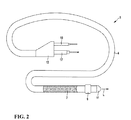
- FIG. 2 shows the application of such an insulating tube 100 using the example of an implantable shock electrode lead 5, which is used in a defibrillator.
- the insulation tube is provided with the reference numeral 4. This can be analogous to that in FIG. 1 illustrated insulation tube 100 or be constructed analogously to one of the embodiments described below.
- the electrode line 5 has a proximal end and a distal end in the longitudinal direction L.
- the shock electrode lead 5 has an elongate electrode 7 which is laid, for example, in wall contact in the heart of a patient, as well as a ring electrode 9 and a tip electrode 11 which are provided for sensing and / or stimulation purposes.
- connector elements 15, 17 extending out of a Y-distributor 13 are provided, which are assigned to the electrode 7 and the stimulation or detection electrodes 9, 11 and for electrical connection to an implantable device (not shown) serve.
- the insulation tube 300 is composed of two layers.
- the inner layer 330 which is formed substantially hollow cylindrical with a through opening 320 for receiving the conductive elements, consists of LSR.
- a second layer 311 is arranged on the outer surface (lateral surface) of the inner layer 320, which analogous to the first embodiment of the insulation tube, an LSR matrix matrix 312 and barium titanate particles 313 with an average diameter of about 2 microns having.
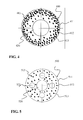
- FIG. 4 shown insulating tube 400 substantially corresponds to the in FIG. 1 shown isolation tube 100, wherein now the barium titanate particles 413 are distributed unevenly across the cross section.
- the concentration of barium titanate particles 413 increases from the inside to the outside. This has the advantage that in the outer region of the cross section, a higher abrasion resistance is achieved in order to protect the insulation tube 400, especially against external friction.
- the abrasion-resistant particles 113, 313 in the respective layer 111, 311 are distributed uniformly over the cross section of the respective layer 111, 311.
- FIG. 5 illustrated fourth embodiment of a spaghetti 500 shows analogous to those in the FIGS. 1 and 3
- the insulation tube has four further continuous, substantially cylindrical openings 521, which evenly around the central opening 520 around are arranged distributed.
- the centers of the cross sections of the openings 521 are arranged approximately on a circle, each offset by about 90 °.
- the cross-section of each opening 521 has a smaller diameter than the cross-section of the central opening 520.
- the openings 520, 521 may be optionally equipped with helical or cable leads in use for an electrode line.
- FIG. 7 illustrated embodiment of an insulating tube 700 substantially corresponds to in FIG. 5 except for the distribution of the barium titanate particles 713. These are not uniformly distributed over the cross section in the insulating tube 700, but their concentration in the layer 711 increases from the inside to the outside, ie, the concentration of the particles 713 has a gradient.
- the concentration of barium titanate particles 613 is also provided, in which case the barium titanate particles 613 are arranged substantially near the outer surface of the layer 611 in an outer sub-layer. The concentration of barium titanate particles 613 therefore does not rise gradually, but rather abruptly in the direction of the outer circumferential surface of the layer 611.
- the abrasion-resistant barium titanate particles 813 are distributed unevenly. They are essentially to be found in sub-layers of the layer 811, which form the outer circumferential surface and the inner surfaces formed by the openings 820, 821. As a result, in particular the abrasion resistance against friction partners, which are arranged in the openings 820, 821, increased. Also in this embodiment, the concentration of the barium titanate particles 813 in the vicinity of the outer circumferential surface and the inner surfaces of the openings 820, 821 tends to increase abruptly.
- the insulating tubes 400, 600, 700, 800 each having the uneven distribution of the particles can be produced, for example, by coextrusion, namely by simultaneously extruding two materials, of which only one is filled with filler material.
- the uneven distributions may be generated by extrusion, with the first layer pre-crosslinked.
- the variant in which the filling material is arranged on the walls (insulation tube 800) could be achieved by adding filler material (in particular of nanoparticles) into the air flow which is required for maintaining the lumens.
- the effect can be improved by static charging of the particles.
- An insulation tube according to the in FIG. 1 The illustrated embodiment was produced with various fillers with increased abrasion resistance, examined by means of a Abriebtests and compared with an insulation tube containing no filling material with increased abrasion resistance.
- the first table presented below shows the results for an abrasion test on abrasion on a rough metal surface rubbing on the insulation tube.
- the hose is pressed with a defined force (here, for example, 4 N) onto a rotating grinding body (here, for example, metal) with defined roughness, here for example with a roughness of Rz 6.3.
- the distance traveled by the grinding wheel (expressed in the number of revolutions) in relation to the removal of the material is a measure of the abrasion resistance of the hose, which is identical Hose geometries can be compared with each other.
- the friction path is the distance traveled by the grinding wheel at the defined force and roughness of the grinding wheel, which is required to achieve a removal of 0.3 mm.
- a base material is extrudately mixed with the filling material and thoroughly mixed before it is extruded into a tube with a conventional extruder for hot-curing materials.
- a multi-filament is inserted as an electrode lead and fixed at the ends by means of adhesive (adhesive).
Landscapes
- Health & Medical Sciences (AREA)
- Life Sciences & Earth Sciences (AREA)
- Heart & Thoracic Surgery (AREA)
- Veterinary Medicine (AREA)
- Public Health (AREA)
- Engineering & Computer Science (AREA)
- General Health & Medical Sciences (AREA)
- Animal Behavior & Ethology (AREA)
- Biomedical Technology (AREA)
- Radiology & Medical Imaging (AREA)
- Nuclear Medicine, Radiotherapy & Molecular Imaging (AREA)
- Cardiology (AREA)
- Orthopedic Medicine & Surgery (AREA)
- Neurology (AREA)
- Neurosurgery (AREA)
- Vascular Medicine (AREA)
- Chemical & Material Sciences (AREA)
- Composite Materials (AREA)
- Materials Engineering (AREA)
- Epidemiology (AREA)
- Electrotherapy Devices (AREA)
- Materials For Medical Uses (AREA)
Abstract
Description
- Die vorliegende Erfindung betrifft einen Isolationsschlauch für eine Elektrodenleitung zur medizinischen Anwendung, insbesondere Herzschrittmacherelektrodenleitung, Defibrillatorelektrodenleitung, Elektrodenleitung zur Nervenstimulation oder dergleichen, enthaltend einen Grundwerkstoff, z.B. Silikon. Die vorliegende Erfindung betrifft ferner eine derartige Elektrodenleitung sowie ein Verfahren zur Herstellung eines Isolationsschlauchs für eine solche Elektrodenleitung und ein Verfahren zur Herstellung einer derartigen Elektrodenleitung.
- Elektronische medizinische Einrichtungen wie Herzschrittmacher (Pacemaker), Defibrillatoren oder neurologische Geräte wie Hirnschrittmacher für tiefe Hirnstimulation (Deep Brain Stimulation), Rückenmarkstimulationsgeräte, TENS (Transcutaneous Electrical Nerve Stimulator) oder Geräte für muskuläre Stimulationstherapie sowie Diagnosegeräte, welche die chemischen Eigenschaften des Blutes des Patienten, anderer Körperteile oder andere Körpereigenschaften und -parameter untersuchen, verwenden häufig Elektrodenleitungen, die in den Körper des Patienten geführt werden und dort zumindest über den Zeitraum der Behandlung oder Messung verbleiben. Die Elektrodenleitungen sind mit der ggf. implantierbaren elektronischen Einrichtung elektrisch leitend verbunden.
- Diese medizinischen Einrichtungen umfassen üblicherweise ein ggf. körperverträgliches Gehäuse mit einer dazugehörigen elektronischen Schaltung und einer Energieversorgung, z.B. einer Batterie. Das Gehäuse besitzt mindestens eine Anschlussstelle, an der die Elektrodenleitung oder die Elektrodenleitungen angeschlossen werden können. Die Elektrodenleitung oder die Elektrodenleitungen dienen der Übertragung der elektrischen Energie vom Gehäuse zu dem behandelten oder untersuchten Körperteil und umgekehrt.
- Hierbei bezeichnet der Begriff "Elektrodenleitung" in der Medizintechnik nicht nur ein Element, mit dem nach physikalischer Definition elektrische Energie übertragen wird, sondern umfasst eine Leitung mit einem elektrischen Leiter zusammen mit seiner umhüllenden Isolation, die häufig als Isolationsschlauch ausgebildet ist, sowie alle weiteren funktionellen Elemente, die mit der Leitung fest verbunden sind. Die Elektrodenleitung umfasst beispielsweise auch die sogenannte Elektrodenspitze, mittels der die elektrische Energie in das zu behandelnde Gewebe eingeleitet wird. Häufig ist eine Elektrodenspitze auch mit Ankerelementen oder Haltestrukturen versehen, mit denen die Konstanz der räumlichen Lage der Übergangsstelle der elektrischen Energie in dem zu behandelnden Gewebe sichergestellt wird. Die Elektrodenspitze, die eine Übergangsstelle der elektrischen Energie in das Gewebe bildet, kann als Ableit-, Stimulations- oder Messelektrode ausgelegt sein.
- Bei derartigen Elektrodenleitungen wird häufig zur Isolation der elektrisch leitenden Elemente außerhalb des Anschlusses und der Elektrodenspitze ein Isolationsschlauch aus Silikon verwendet. Silikone weisen eine hohe Biokompatibilität, eine ausreichende Härte sowie sehr gute dauerelastische Eigenschaften auf.
- Reibt eine Elektrodenleitung beispielsweise am Schlüsselbein oder an einer zweiten Elektrodenleitung (z.B. wenn mehrere Elektrodenleitungen implantiert sind), so kann es vorkommen, dass der Isolationsschlauch so weit durchgerieben wird, dass die Funktionsfähigkeit der Elektrodenleitung beeinträchtigt wird.
- Aus diesem Grund wurde bereits nach Wegen gesucht, die Abriebfestigkeit eines Isolationsschlauchs zu erhöhen.
- In der Druckschrift
DE 10 2008 010 188 A1 wurde beispielsweise ein Isolationsschlauch vorgeschlagen, bei dem auf der Mantelfläche einer inneren, hohlzylinderförmigen Schicht eine zweite Schicht angeordnet ist, welche mindestens ein Polymer aus der Gruppe bestehend aus Polyurethan und Silikon-Polyurethan-Copolymer enthält. Polyurethan besitzt jedoch für viele Einsatzzwecke keine ausreichende Langzeitstabilität, da das Material mit der Zeit degradiert. Auch bei der vorgeschlagenen Zwei-Schicht-Lösung kann eine Degradation des Materials nicht grundsätzlich ausgeschlossen werden. Zudem ist eine solche Elektrodenleitung aufgrund der Anordnung von zwei Schichten übereinander deutlich härter als eine einschichtige Elektrodenleitung mit Silikonisolation. Dieser Effekt ist insbesondere für dünne Elektrodenleitungen relevant. Ferner ist das Konzept, einen Isolationsschlauch aus zwei koaxial angeordneten Schichten zu verwenden, fertigungstechnisch recht aufwendig. - In weiteren, bereits bekannten Lösungen wurden neue Werkstoffe entwickelt, welche die Eigenschaften von Silikon und Polyurethan verbinden, beispielsweise die Copolymere Pursil (Silikonpolyetherurethan), Carbosil (Polycarbonaturethan) oder Elast-Eon®. Diese Materialien sind noch so neu, dass für sie Langzeiterfahrungen fehlen. Demzufolge ist der Einsatz dieser Materialien für medizinische Anwendungen aufgrund umfangreicher notwendiger Tests ebenfalls aufwendig.
- Die Aufgabe der vorliegenden Erfindung besteht somit darin, einen Isolationsschlauch bzw. eine entsprechende Elektrodenleitung anzugeben, welche ein verbessertes Abriebverhalten aufweisen, ohne dass die Biokompatibilität oder die sonstigen mechanischen Eigenschaften wesentlich beeinträchtigt werden. Die Aufgabe besteht ferner darin, einfache und kostengünstige Verfahren zur Herstellung eines derartigen Isolationsschlauchs bzw. einer derartigen Elektrodenleitung anzugeben.
- Die obige Aufgabe wird gelöst durch einen Isolationsschlauch enthaltend einen Grundwerkstoff aus mindestens einem Material der Gruppe enthaltend Silikone, Polyurethane, Polyimid, PTFE, ETFE, Copolymere aus Silikonen und Polyurethanen, wobei der Isolationsschlauch zumindest in einem vorzugsweise die Mantelfläche ausbildenden Volumenbereich zusätzlich zu dem Grundwerkstoff ein partikelförmiges und/oder faserförmiges Füllmaterial aufweist, welches eine höhere Abriebfestigkeit als der jeweils verwendete Grundwerkstoff besitzt.
- Das Füllmaterial ist vorzugsweise kugel-, bohnen- und/oder kornförmige Partikel und/oder als Faser, Faserabschnitt oder Fasergeflecht, ausgebildet.
- Zur Herstellung eines erfindungsgemäßen Isolationsschlauchs werden beispielsweise kleine Füllpartikel oder Faserabschnitte dem Extrudat beigemengt und anschließend zu einem Schlauch extrudiert oder zu einem Formteil ausgespritzt. Lange Fasern können beispielsweise in den Schlauch eingeflochten werden. Hierfür werden die Fasern um ein Schlauch-Innenteil oder ein Formteil herum geflochten, welches seinerseits nun noch einmal umspritzt wird. Eine andere Möglichkeit des Einflechtens von Fasern besteht darin, die Fasern um einen Kern herum zu flechten, der danach umspritzt und/oder auf den aufextrudiert wird, wobei der Kern später entfernt wird. Als Geflecht eignet sich besonders ein Kreuzgeflecht, dessen Fasern, z. B. aus Polyethylenterephthalat (PET), gitterartig um das Lumen geflochten sind. Weitere Möglichkeiten und Einzelheiten zur Herstellung eines erfindungsgemäßen Isolationsschlauchs werden unten erläutert.
- Der Vorteil des erfindungsgemäßen Isolationsschlauchs besteht darin, dass Grundwerkstoff nach wie vor die Eigenschaften des Isolationsschlauchs wie Biokompatibilität wesentlich bestimmt. Bei einem Angriff durch einen Reibepartner wird der Abrieb jedoch durch die in die Grundwerkstoff-Matrix eingebetteten abriebfesten Partikel oder Fasern gestoppt. Demzufolge kann bei einem erfindungsgemäßen Isolationsschlauch die Abriebfestigkeit insgesamt deutlich erhöht werden. Hinsichtlich der Eigenschaften Elastizität und Härte muss der Grundwerkstoff lediglich geringfügig angepasst werden, so dass das Gesamtmaterial aus Grundwerkstoff und Füllmaterial die gewünschte Gesamtelastizität und Gesamthärte auf weist.
- Die vorliegende Erfindung beruht daher auf der Erkenntnis, dass nicht das gesamte Material des Isolationsschlauchs verändert werden muss, um die gewünschte Abriebfestigkeit zu erreichen. Es ist vielmehr ausreichend, wenn lediglich ein geringer Anteil (Konzentrationsangaben siehe unten) des Materials durch ein abriebfesteres Füllmaterial ersetzt wird. Hierbei ist das partikelförmige und/oder faserförmige Füllmaterial hinsichtlich der Phase oder Phasenzusammensetzung verschieden von dem Grundwerkstoff. Dies bedeutet, dass in einem Partikel oder einer Faser bzw. einem Faserabschnitt ein räumlicher Bereich ausgebildet ist, in dem die bestimmenden physikalischen Parameter der Materie verschieden von den physikalischen Parametern der Materie des Grundwerkstoffs sind. Vorzugsweise besteht ein Partikel oder eine Faser bzw. ein Faserabschnitt aus einer einzigen Phase, d.h. einem hinsichtlich der physikalischen Parameter der Materie homogenen räumlichen Bereich.
- In der vorliegenden Erfindung wird unter einem Silikon ein Poly(organo)siloxan, d.h. ein Polymer verstanden, bei dem Siliziumatome über Sauerstoffatome verknüpft sind. Ein solches Silikon kann Molekülketten und/oder -netze enthalten. Die restlichen freien Valenzelektronen des Siliziums sind dabei durch Kohlenwasserstoffreste abgesättigt. Für die vorliegende medizinische Anwendung eines Isolationsschlauchs werden insbesondere die folgenden Silikonkautschuke eingesetzt, vorzugsweise heißvernetzender Flüssigsilikonkautschuk (high temperature vulcanizing liquid silicone rubber oder kurz HTV LSR), der aus einer (zäh)flüssigen Phase extrudiert und bei hohen Temperaturen entweder peroxidisch induziert oder Platin-katalysiert vernetzt wird.
- Vorteilhafte Werkstoffe, die das Füllmaterial bilden können, sind mindestens ein Werkstoff der Gruppe bestehend aus Kohlenstoff, Tantal, Platin, Gold, Iridium, Palladium, Silikonderivate, Copolymere aus Silikonen, keramisches Material, insbesondere Siliziumcarbid, Bariumtitanat, Titandioxid und Zirkoniumdioxid, und thermoplastisches Material, insbesondere Polyurethan, Polyamid, Polyethylen, Polyimid, PTFE (Polytetrafluorethylen), PFA (Perfluor-Alkoxyalkan), PET (Polyethylenterephthalat) und ETFE (Ethylen-Tetrafluorethylen).
- Es soll an dieser Stelle ausdrücklich darauf hingewiesen werden, dass bei der Auswahl von Materialien aus den angegebenen Gruppen für den Grundwerkstoff und das Füllmaterial zur Realisierung der Erfindung stets Materialien mit unterschiedlichen Abriebfestigkeiten selektiert werden, wobei das Füllmaterial eine höhere Abriebfestigkeit besitzt als der Grundwerkstoff. Dies kann durch Auswahl unterschiedlicher Materialklassen oder durch Auswahl unterschiedlicher Varianten derselben, beispielsweise polymeren Materialklasse erfolgen. Bei der Verwendung unterschiedlicher Varianten ein und derselben Materialklasse für Grundwerkstoff und Füllmaterial kann unter Umständen eine sehr gute Verbundfestigkeit zwischen den Materialien von Grundwerkstoff und Füllmaterial erreicht werden. Beispielsweise kann das Füllmaterial aus bereits vernetzten Fasern aus abriebfesterem Silikon hergestellt werden. Dieses Füllmaterial kann dann der Extrusionsmasse aus überwiegend Silikon beigemengt werden, wobei sich das Füllmaterial, da es bereits vernetzt ist, dabei nicht auflöst.
- Die Abriebfestigkeit kann insbesondere dann erhöht werden, wenn der Anteil des Füllmaterials an dem Material des Isolationsschlauchs 0,1 Vol.% bis 30 Vol.%, vorzugsweise 1 Vol.% bis 15 Vol.%, beträgt. Füllmaterial aus sehr kleinen Partikeln oder Fasern (Nanomaterial) wird besonders bevorzugt in geringeren Konzentrationen im Bereich von 1 Vol.% bis 5 Vol.% zugefügt. Wie oben bereits erläutert wurde, ist, wie angegeben, bereits ein geringer Anteil an Füllmaterial mit einer höheren Abriebfestigkeit ausreichend, um die Eigenschaften des Isolationsschlauchs hinsichtlich des Abriebs signifikant zu verbessern, ohne die Eigenschaften wie Biokompatibilität des Matrix-Grundwerkstoffs zu beeinträchtigen. Bei diesen Konzentrationen wird bei der Verwendung von elektrisch leitendem Füllmaterial insgesamt auch die elektrische Isolierung der Elektrodenleitung durch den Isolationsschlauch ausreichend gewährleistet.
- In einem weiteren bevorzugten Ausführungsbeispiel beträgt der Durchmesser des partikelförmigen Füllmaterials 1 nm bis 100 nm, vorzugsweise 20 nm bis 60 nm, (Nanopartikel). Hierbei wird der Durchmesser des partikelförmigen Füllmaterials insbesondere durch Vermessung im REM (Rasterelektronenmikroksop) bestimmt. Kleinere Partikel haben den Vorteil, dass diese bei gleichem Effekt hinsichtlich Abriebfestigkeit in geringerer Menge eingesetzt werden können. Insbesondere in dem zweiten angegebenen Konzentrationsbereich sind die Partikel auch noch gut verarbeitbar.
- Aus gleichen Gründen beträgt in einem weiteren bevorzugten Ausführungsbeispiel die Länge des faserförmigen Füllmaterials 0,1 mm bis 10 mm. Hierbei wird die Länge des faserförmigen Füllmaterials insbesondere durch die gewünschte resultierende Steifigkeit des extrudierten oder gespritzten Schlauches bestimmt und stellt die Ausdehnung der Fasern in Längsrichtung dar. Insbesondere längere Fasern erhöhen in vorteilhafter Weise die Biegesteifigkeit des Isolationsschlauchs. In dieser Hinsicht ist es ebenfalls von Vorteil, wenn die Länge des faserförmigen Füllmaterials etwa das 10-fache bis 100-fache des Faserdurchmessers beträgt.
- Besonders gute Ergebnisse zur Abriebfestigkeit werden erreicht, wenn das faserförmige Füllmaterial mindestens überwiegend derart ausgerichtet ist, dass die Längsrichtung der Fasern parallel zu einer Längsachse des Isolationsschlauchs verläuft. Hierbei wird unter Längsrichtung einer Faser die Richtung der jeweiligen Faser verstanden, entlang der die Faser die größte Ausdehnung besitzt. Die Längsausrichtung der Fasern führt zu einer axialen Verkrallung der resultierenden Schutzschicht. Bei einer Biegebeanspruchung des Schlauchmaterials wird so einer Kerbwirkung senkrecht zur Schlauchachse und damit einer Bruchgefahr entgegengewirkt. Radial angeordnete Fasern können die Biegelastwechselfestigkeit des Isolationsschlauches negativ beeinflussen.
- Vorzugsweise ist das Füllmaterial über den Querschnitt des Isolationsschlauchs ungleichmäßig verteilt, beispielsweise lediglich in einer Schicht oder Teilschicht oder mit einem Gradienten. Bei ungleichmäßiger Verteilung des Füllmaterials werden gezielt die Bereiche des Isolationsschlauchs mit dem Füllmaterial versehen, die besonders gegen Abrieb geschützt werden sollen, beispielsweise die Bereiche in der Nähe der äußeren Mantelfläche des Isolationsschlauchs und/oder in der Nähe der Innenwand der Öffnung(en) in dem Isolationsschlauch, in der oder denen die Leiterelemente angeordnet sind.
- Die obige Aufgabe wird mit den oben dargestellten Vorteilen auch durch eine Elektrodenleitung gelöst, welche einen Isolationsschlauch mit oben angegebenen Eigenschaften aufweist, wobei der Isolationsschlauch in einem Abschnitt der Elektrodenleitung, in dem dieser angeordnet ist, vorzugsweise die äußere Oberfläche der Elektrodenleitung ausbildet bzw. die Elektrode außen umgibt. Der Isolationsschlauch isoliert die inneren elektrisch leitenden Elemente der Elektrodenleitung nach außen und stellt zusätzlich einen Schutz gegen mechanische Reibung mit einem Reibepartner dar.
- Ein einfaches und kostengünstiges Verfahren zur Herstellung eines erfindungsgemäßen Isolationsschlauchs besteht aus den folgenden Schritten:
- Bereitstellen mindestens eines ersten Grundwerkstoffs aus mindestens einem Material der Gruppe enthaltend Silikone, Polyurethane, Polyimid, PTFE, ETFE, Copolymere aus Silikonen und Polyurethanen, sowie eines partikelförmigen und/oder faserförmigen Füllmaterials, wobei das Füllmaterial eine höhere Abriebfestigkeit als der erste Grundwerkstoff aufweist,
- Mischen des ersten Grundwerkstoffs und des Füllmaterials,
- Formen des ein- oder mehrschichtigen Isolationsschlauchs durch
- Extrudieren oder Spritzen (Molding) der Mischung aus dem ersten Grundwerkstoff und dem Füllmaterial zu einem einschichtigen Isolationsschlauch oder
- Koextrusion der Mischung aus dem ersten Grundwerkstoff und dem Füllmaterial mit mindestens einem zweiten Grundwerkstoff aus mindestens einem Material der Gruppe enthaltend Silikone, Polyurethane, Polyimid, PTFE, ETFE, Copolymere aus Silikonen und Polyurethanen, zu einem mindestens doppelschichtigen Isolationsschlauch oder
- ein- oder mehrmalige Aufextrusion der Mischung aus dem ersten Grundwerkstoff und dem Füllmaterial auf einen Schlauch mit mindestens einem zweiten Grundwerkstoff aus mindestens einem Material der Gruppe enthaltend Silikone, Polyurethane, Polyimid, PTFE, ETFE, Copolymere aus Silikonen und Polyurethanen, zu einem mindestens doppelschichtigen Isolationsschlauch oder
- ein- oder mehrmaliges Umspritzen (Molding) der Mischung aus dem ersten Grundwerkstoff und dem Füllmaterial um einen Schlauch mit mindestens einem zweiten Grundwerkstoff aus mindestens einem Material der Gruppe enthaltend Silikone, Polyurethane, Polyimid, PTFE, ETFE, Copolymere aus Silikonen und Polyurethanen, zu einem mindestens doppelschichtigen Isolationsschlauch oder
- ein- oder mehrmaliges Tauchen (Dipping) eines Schlauchs mit mindestens einem zweiten Grundwerkstoff aus mindestens einem Material der Gruppe enthaltend Silikone, Polyurethane, Polyimid, PTFE, ETFE, Copolymere aus Silikonen und Polyurethanen in eine Mischung aus dem flüssigen ersten Grundwerkstoff und dem Füllmaterial, zur Erzeugung eines mindestens doppelschichtigen Isolationsschlauchs,
- In einem besonders bevorzugten Ausführungsbeispiel wird ein Schlauch mit dem zweiten Grundwerkstoff in dünnflüssiges Silikon (besonders bevorzugt RTV-Silikon), das mit dem genannten Füllmaterial versetzt ist, getaucht.
- Ein weiteres kostengünstiges Verfahren zur Herstellung eines erfindungsgemäßen Isolationsschlauchs weist die folgenden Schritte auf:
- Bereitstellen mindestens eines faserverstärkten ersten Grundwerkstoffs aus mindestens einem Material der Gruppe enthaltend Silikone, Polyurethane, Polyimid, PTFE, ETFE, Copolymere aus Silikonen und Polyurethanen, wobei das Material der Fasern eine höhere Abriebfestigkeit als der erste Grundwerkstoff aufweist,
- Formen des ein- oder mehrschichtigen Isolationsschlauchs durch
- Extrudieren des faserverstärkten ersten Grundwerkstoffs zu einem einschichtigen Isolationsschlauch oder
- Koextrusion des faserverstärkten ersten Grundwerkstoffs mit mindestens einem zweiten Grundwerkstoff aus mindestens einem Material der Gruppe enthaltend Silikone, Polyurethane, Polyimid, PTFE, ETFE, Copolymere aus Silikonen und Polyurethanen, zu einem mindestens doppelschichtigen Isolationsschlauch oder
- ein- oder mehrmalige Aufextrusion des faserverstärkten ersten Grundwerkstoffs auf einen Schlauch mit mindestens einem zweiten Grundwerkstoff aus mindestens einem Material der Gruppe enthaltend Silikone, Polyurethane, Polyimid, PTFE, ETFE, Copolymere aus Silikonen und Polyurethanen, zu einem mindestens doppelschichtigen Isolationsschlauch oder
- ein- oder mehrmaliges Umspritzen (Molding) des faserverstärkten ersten Grundwerkstoffs um einen Schlauch mit mindestens einem zweiten Grundwerkstoff aus mindestens einem Material der Gruppe enthaltend Silikone, Polyurethane, Polyimid, PTFE, ETFE, Copolymere aus Silikonen und Polyurethanen, zu einem mindestens doppelschichtigen Isolationsschlauch oder
- ein- oder mehrmaliges Tauchen (Dipping) eines Schlauchs mit mindestens einem zweiten Grundwerkstoff aus mindestens einem Material der Gruppe enthaltend Silikone, Polyurethane, Polyimid, PTFE, ETFE, Copolymere aus Silikonen und Polyurethanen in einen flüssigen faserverstärkten ersten Grundwerkstoff zur Erzeugung eines mindestens doppelschichtigen Isolationsschlauchs,
- Bei der Verwendung eines Fasergeflechts kann das folgende kostengünstige erfindungsgemäße Verfahren zur Herstellung eines Isolationsschlauchs eingesetzt werden:
- Bereitstellen eines Fasergeflechts und eines ersten Grundwerkstoffs aus mindestens einem Material der Gruppe enthaltend Silikone, Polyurethane, Polyimid, PTFE, ETFE, Copolymere aus Silikonen und Polyurethanen, wobei das Material der Fasern eine höhere Abriebfestigkeit als der erste Grundwerkstoff aufweist,
- Aufbringen des Fasergeflechts auf einen Kern oder auf einen Schlauch mit mindestens einem zweiten Grundwerkstoff aus mindestens einem Material der Gruppe enthaltend Silikone, Polyurethane, Polyimid, PTFE, ETFE, Copolymere aus Silikonen und Polyurethanen oder ein Formteil mit mindestens einem zweiten Grundwerkstoff aus mindestens einem Material der Gruppe enthaltend Silikone, Polyurethane, Polyimid, PTFE, ETFE, Copolymere aus Silikonen und Polyurethanen
- Formen des ein- oder mehrschichtigen Isolationsschlauchs durch
- ein- oder mehrmalige Aufextrusion des ersten Grundwerkstoffs auf das Fasergeflecht oder
- ein- oder mehrmaliges Umspritzen (Molding) des ersten Grundwerkstoffs um das Fasergeflecht oder
- ein- oder mehrmaliges Tauchen (Dipping) des Fasergeflechts oder des Fasergeflechts mit Schlauch oder mit Formteil in mindestens den flüssigen ersten Grundwerkstoff,
- Vorteilhafte Werkstoffe, die das Füllmaterial, d.h. die Partikel oder Fasern, bilden können, sind mindestens ein Werkstoff der Gruppe bestehend aus Kohlenstoff, Tantal, Platin, Gold, Iridium, Palladium, keramisches Material, insbesondere Siliziumcarbid, Bariumtitanat, Titandioxid und Zirkoniumdioxid, und thermoplastisches Material, insbesondere Polyurethan, Polyamid, Polyethylen, Polyimid, PTFE (Polytetrafluorethylen), PFA (Perfluor-Alkoxyalkan), PET (Polyethylenterephthalat) und ETFE (Ethylen-Tetrafluorethylen).
- Die Extrusion und die Koextrusion sind einfache, gut beherrschbare Verfahren für die Herstellung eines Isolationsschlauchs mit erhöhter Abriebfestigkeit. Bei diesem Verfahren ist ferner von Vorteil, dass die Schichtdicke und die Konzentration des Füllmaterials in der jeweiligen Schicht einfach und individuell einstellbar ist. Zudem kann in der jeweiligen Schicht eine gute Durchmischung des Silikon-Grundmaterials mit dem Füllmaterial erreicht werden.
- Die obige Aufgabe wird ferner durch ein Verfahren zur Herstellung einer Elektrodenleitung gelöst, bei dem ein Isolationsschlauch wie oben dargestellt hergestellt wird und anschließend der Isolationsschlauch so auf einem und/oder um ein Leiterelement angeordnet wird, dass er dieses außen umgibt. Der Isolationsschlauch dient sowohl zur elektrischen Isolierung des Leiterelements als auch zu dessen mechanischen Schutz gegen Abrieb. Auch dieses Herstellungsverfahren ist insbesondere aufgrund der oben genannten Vorteile für die Herstellung des Isolationsschlauchs einfach und kostengünstig.
- Weitere Ziele, Merkmale, Vorteile und Anwendungsmöglichkeiten der Erfindung ergeben sich aus der nachfolgenden Beschreibung von Ausführungsbeispielen und den Figuren. Dabei bilden aller beschriebenen und/oder bildlich dargestellten Merkmale für sich oder in beliebiger Kombination den Gegenstand der Erfindung, auch unabhängig von ihrer Zusammenfassung in den Ansprüchen oder deren Rückbeziehung.
- Es zeigen schematisch:
- Fig. 1
- einen Querschnitt eines ersten Ausführungsbeispiels eines erfindungsgemäßen Isolationsschlauchs,
- Fig. 2
- ein Ausführungsbeispiel einer erfindungsgemäßen Elektrodenleitung in einer Ansicht von der Seite,
- Fig. 3
- einen Querschnitt eines zweiten Ausführungsbeispiel eines erfindungsgemäßen Isolationsschlauchs,
- Fig. 4
- einen Querschnitt eines dritten Ausführungsbeispiels eines erfindungsgemäßen Isolationsschlauchs,
- Fig. 5
- einen Querschnitt eines vierten Ausführungsbeispiels eines erfindungsgemäßen Isolationsschlauchs,
- Fig. 6
- einen Querschnitt eines fünften Ausführungsbeispiels eines erfindungsgemäßen Isolationsschlauchs,
- Fig. 7
- einen Querschnitt eines sechsten Ausführungsbeispiels eines erfindungsgemäßen Isolationsschlauchs und
- Fig. 8
- einen Querschnitt eines siebten Ausführungsbeispiels eines erfindungsgemäßen Isolationsschlauchs.
- Der in
Figur 1 dargestellte Isolationsschlauch 100 weist lediglich eine einzige Schicht 111 auf, welche im Wesentlichen hohlzylindrisch ausgebildet ist. Die Schicht 111 setzt sich zusammen aus einer Grundwerkstoff-Matrix 112 aus LSR (Liquid Silicone Rubber, Flüssigsilikon mit dem Hauptbestandteil lineare Siloxane), in die kugelförmige Partikel 113, beispielsweise aus Bariumtitanat, als Füllmaterial eingebettet sind. Derartige Bariumtitanat-Partikel 113 weisen einen mittleren Durchmesser von etwa 2 µm auf. Alternativ oder zusätzlich können auch Tantal-Partikel als Füllmaterial in die Grundwerkstoff-Matrix eingebettet werden. Diese haben einen mittleren Durchmesser von etwa 40 µm. Die durchgehende zylinderförmige Öffnung 120 des Isolationsschlauchs 100 dient der Aufnahme der leitenden Elemente, welche am distalen Ende der Elektrodenleitung die Elektrode oder die Elektroden und am proximalen Ende ein Verbindungselement zur elektrisch leitenden Verbindung mit einer elektronischen Einrichtung ausbilden. Die Bariumtitanat-Partikel und/oder die Tantal-Partikel 113 besitzen jeweils eine höhere Abriebfestigkeit als der Grundwerkstoff LSR 112. -
Figur 2 zeigt die Anwendung eines derartigen Isolationsschlauchs 100 am Beispiel einer implantierbaren Schockelektrodenleitung 5, welche in einem Defibrillator eingesetzt wird. InFigur 2 ist der Isolationsschlauch mit dem Bezugszeichen 4 versehen. Dieser kann analog zu dem inFigur 1 dargestellten Isolationsschlauch 100 oder analog zu einem der nachfolgend beschriebenen Ausführungsbeispiele aufgebaut sein. Die Elektrodenleitung 5 weist in Längsrichtung L ein proximales Ende und ein distales Ende auf. An dem distalen Ende besitzt die Schockelektrodenleitung 5 eine langgestreckte Elektrode 7, die z.B. in Wandkontakt im Herzen eines Patienten verlegt wird, sowie eine Ring-Elektrode 9 und eine Tip-Elektrode 11, welche für Abtast- und/oder Stimulationszwecke vorgesehen sind. Am proximalen Ende der Schockelektrodenleitung 5 sind aus einem Y-Verteiler 13 sich hinaus erstreckende Steckerelemente 15, 17 vorgesehen, die der Elektrode 7 und den Stimulations- bzw. Detektionselektroden 9,11 zugeordnet sind und zur elektrischen Verbindung mit einem (nicht dargestellten) implantierbaren Gerät dienen. - In dem in
Figur 3 dargestellten zweiten Ausführungsbeispiel ist der Isolationsschlauch 300 aus zwei Schichten aufgebaut. Die innere Schicht 330, die im Wesentlichen hohlzylindrisch mit einer durchgehenden Öffnung 320 zur Aufnahme der leitenden Elemente geformt ist, besteht aus LSR. Konzentrisch zur inneren Schicht 320 ist eine zweite Schicht 311 auf der äußeren Oberfläche (Mantelfläche) der inneren Schicht 320 angeordnet, welche analog zu dem ersten Ausführungsbeispiel des Isolationsschlauchs eine LSR Grundwerkstoff-Matrix 312 und Partikel 313 aus Bariumtitanat mit einem mittleren Durchmesser von etwa 2 µm aufweist. - Der Aufbau des in
Figur 4 dargestellten Isolationsschlauchs 400 entspricht im Wesentlichen dem inFigur 1 gezeigten Isolationsschlauch 100, wobei nun die Bariumtitanat-Partikel 413 ungleichmäßig über den Querschnitt verteilt sind. Die Konzentration der Bariumtitanat-Partikel 413 nimmt von innen nach außen zu. Dies hat den Vorteil, dass im äußeren Bereich des Querschnitts eine höhere Abriebfestigkeit erreicht wird, um den Isolationsschlauch 400 vor allem gegen äußere Reibung zu schützen. - In den in den
Figuren 1 und2 dargestellten Ausführungsbeispielen sind demgegenüber die abriebfesten Partikel 113, 313 in der jeweiligen Schicht 111, 311 gleichmäßig über den Querschnitt der jeweiligen Schicht 111, 311 verteilt. - Das in
Figur 5 dargestellte vierte Ausführungsbeispiel eines Isolationsschlauchs 500 zeigt analog zu den in denFiguren 1 und3 dargestellten Ausführungsbeispielen eine gleichmäßige Verteilung der Bariumtitanat-Partikel 513 über den Querschnitt der Schicht 511. Neben einer mittigen, durchgehenden, im Wesentlichen zylinderförmigen Öffnung 520 weist der Isolationsschlauch vier weitere durchgehende, im Wesentlichen zylinderförmige Öffnungen 521 auf, welche gleichmäßig um die mittige Öffnung 520 herum verteilt angeordnet sind. Die Mittelpunkte der Querschnitte der Öffnungen 521 sind etwa auf einem Kreis, jeweils etwa um 90° versetzt angeordnet. Der Querschnitt jeder Öffnung 521 hat einen kleineren Durchmesser als der Querschnitt der mittigen Öffnung 520. Die Öffnungen 520, 521 können im Einsatz für eine Elektrodenleitung wahlweise mit Wendel- oder Seilzuleitungen bestückt sein. - Das in
Figur 7 dargestellte Ausführungsbeispiels eines Isolationsschlauchs 700 entspricht im Wesentlichen der inFigur 5 dargestellten Ausführungsform bis auf die Verteilung der Bariumtitanat-Partikel 713. Diese sind bei dem Isolationsschlauch 700 nicht gleichmäßig über den Querschnitt verteilt, sondern ihre Konzentration in der Schicht 711 nimmt von innen nach außen zu, d.h. die Konzentration der Partikel 713 weist einen Gradienten auf. In dem inFigur 6 dargestellten Ausführungsbeispiel eines Isolationsschlauchs 600 ist ebenfalls eine ungleichmäßige Verteilung der Bariumtitanat-Partikel 613 vorgesehen, wobei hier die Bariumtitanat-Partikel 613 im Wesentlichen nahe der äußeren Mantelfläche der Schicht 611 in einer äußeren Teilschicht angeordnet sind. Die Konzentration der Bariumtitanat-Partikel 613 steigt daher nicht graduell an, sondern eher sprunghaft in Richtung der äußeren Mantelfläche der Schicht 611. - Auch bei dem in
Figur 8 dargestellten Ausführungsbeispiel eines Isolationsschlauchs 800 sind die abriebfesten Bariumtitanat-Partikel 813 ungleichmäßig verteilt. Sie sind im Wesentlichen in Teilschichten der Schicht 811 zu finden, welche die äußere Mantelfläche und die durch die Öffnungen 820, 821 geformten Innenflächen ausbilden. Hierdurch wird insbesondere die Abriebfestigkeit gegenüber Reibepartnern, die in den Öffnungen 820, 821 angeordnet sind, erhöht. Auch bei diesem Ausführungsbeispiel steigt die Konzentration der Bariumtitanat-Partikel 813 in der Nähe der äußeren Mantelfläche und der Innenflächen der Öffnungen 820, 821 eher sprunghaft an. - Die Isolationsschläuche 400, 600, 700, 800 mit jeweils der ungleichmäßigen Verteilung der Partikel können beispielsweise durch Coextrusion hergestellt werden, nämlich indem zwei Materialien, von denen nur das eine mit Füllmaterial versetzt ist, gleichzeitig extrudiert werden. Alternativ können die ungleichmäßigen Verteilungen mittels Aufextruieren erzeugt werden, wobei die erste Schicht vorvernetzt ist. Die Variante, bei der das Füllmaterial an den Wandungen angeordnet ist (Isolationsschlauch 800), könnte durch Beimengung von Füllmaterial (insbesondere von Nanopartikeln) in den Luftstrom, der zum Aufrechthalten der Lumen erforderlich ist, erzielt werden. Gegebenenfalls kann der Effekt durch statische Aufladung der Partikel verbessert werden.
- Ein Isolationsschlauch gemäß dem in
Figur 1 abgebildeten Ausführungsbeispiel wurde mit verschiedenen Füllmaterialien mit erhöhter Abriebfestigkeit produziert, mittels eines Abriebtests untersucht und mit einem Isolationsschlauch, der kein Füllmaterial mit erhöhter Abriebfestigkeit enthielt, verglichen. Die unten dargestellte erste Tabelle zeigt die Ergebnisse für einen Abriebtest bei dem Abrieb an einer rauen Metalloberfläche, die auf dem Isolationsschlauch reibt. Bei dem Abriebtest wird der Schlauch mit einer definierten Kraft (hier z.B. 4 N) auf einen rotierenden Schleifkörper (hier z.B. Metall) mit definierter Rauigkeit, hier beispielsweise mit einer Rauigkeit von Rz 6,3, gedrückt. Der zurückgelegte Weg des Schleifkörpers (ausgedrückt in der Anzahl seiner Umdrehungen) im Verhältnis zum Abtrag des Materials ist ein Maß für die Abriebfestigkeit des Schlauches, welches bei identischen Schlauchgeometrien untereinander verglichen werden kann. Hierbei ist im Folgenden der Reibweg der zurückgelegte Weg des Schleifkörpers bei der definierten Kraft und der definierten Rauigkeit des Schleifkörpers, der benötigt wird, um einen Abtrag von 0,3 mm zu erreichen.Grundwerkstoff Füllmaterial mit erhöhter Abriebfestigkeit Anteil (in Vol.%) / Partikelgröße Reibweg des metallischen Abriebpartners (Rauigkeit Rz 6,3 / Kraft 4 N) Abriebresistenz (Faktor) Silikonschlauch aus LSR, mit einer Härte von 50 Shore - 0% 20 m 1 Silikonschlauch aus LSR, mit einer Härte von 50 Shore Bariumtitanat 15% / 3 µm 60 m 3 Silikonschlauch aus LSR, mit einer Härte von 50 Shore Tantal 15% / 44 µm 100 m 5 - Die oben dargestellten Ergebnisse zeigen, dass das Abriebverhalten eines Silikon-Isolationsschlauches mit dem angegebenen Füllmaterial gegenüber einem Silikon-Isolationsschlauch ohne Füllmaterial bei einem Abriebpartner aus Metall mit definierter Rauheit deutlich verbessert wird. Eine solche Verbesserung wird bereits durch eine mengenmäßig geringe Zugabe von lediglich 15 Vol% erreicht.
- Zur Herstellung eines Isolationsschlauchs mit Elektrodenleitung wird ein Grundwerkstoff extrudat mit dem Füllmaterial versetzt und sorgfältig vermischt, bevor es mit einem herkömmlichen Extruder für heißvernetzende Werkstoffe zu einem Schlauch extrudiert wird. In diesen Schlauch wird eine Mehrfachwendel als Elektrodenzuleitung eingeschoben und an den Enden mittels Adhesive (Klebstoff) fixiert.
-
- 4, 100, 300, 400, 500, 600, 700, 800
- Isolationsschlauch
- 5
- Schockelektrodenleitung
- 7
- Elektrode
- 9
- Ring-Elektrode
- 11
- Tip-Elektrode
- 13
- Y-Verteiler
- 15, 17
- Steckerelement
- 111,311,411,511,611,711,811
- Schicht
- 112, 312, 412, 512, 612, 712, 812
- Grundwerkstoff
- 113, 313, 413, 513, 613, 713, 813
- Partikel
- 120, 320, 420, 520, 620, 720, 820
- Öffnung
- 521,621,721,821
- Öffnung
- 330
- Schicht
- L
- Längsrichtung der Schockelektrodenleitung 5
Claims (13)
- Isolationsschlauch (4, 100, 300, 400, 500, 600, 700, 800) für eine Elektrodenleitung (5) zur medizinischen Anwendung, insbesondere Herzschrittmacherelektrodenleitung, Defibrillatorelektrodenleitung, Elektrodenleitung zur Nervenstimulation oder dergl., enthaltend einen Grundwerkstoff (112, 312, 412, 512, 612, 712, 812) aus mindestens einem Material der Gruppe enthaltend Silikone, Polyurethane, Polyimid, PTFE, ETFE, Copolymere aus Silikonen und Polyurethanen, wobei der Isolationsschlauch (4, 100, 300, 400, 500, 600, 700, 800) zumindest in einem vorzugsweise die Mantelfläche des Isolationsschlauchs (4, 100, 300, 400, 500, 600, 700, 800) ausbildendem Volumenbereich zusätzlich zu dem Grundwerkstoff (112, 312, 412, 512, 612, 712, 812) ein faserförmiges und/oder partikelförmiges Füllmaterial (113, 313, 413, 513, 613, 713, 813) aufweist, welches eine höhere Abriebfestigkeit als der jeweilige Grundwerkstoff (112, 312, 412, 512, 612, 712, 812) besitzt.
- Isolationsschlauch (4, 100, 300, 400, 500, 600, 700, 800) nach Anspruch 1, dadurch gekennzeichnet, dass das Füllmaterial (113, 313, 413, 513, 613, 713, 813) mindestens ein Material der Gruppe enthaltend Kohlenstoff, Tantal, Platin, Gold, Iridium, Palladium, Silikonderivate, Copolymere aus Silikonen, keramisches Material, insbesondere Siliziumcarbid, Bariumtitanat, Titandioxid und Zirkoniumdioxid, und thermoplastisches Material, insbesondere Polyurethan, Polyamid, Polyethylen, Polyimid, PET, PFA, PTFE und ETFE, umfasst.
- Isolationsschlauch (4, 100, 300, 400, 500, 600, 700, 800) nach einem der vorhergehenden Ansprüche, dadurch gekennzeichnet, dass der Anteil des Füllmaterials (113, 313, 413, 513, 613, 713, 813) an dem Material des Isolationsschlauchs (4, 100, 300, 400, 500, 600, 700, 800) 0,1 Vol.% bis 30 Vol.%, vorzugsweise 1 Vol.% bis 15 Vol.%, beträgt.
- Isolationsschlauch (4, 100, 300, 400, 500, 600, 700, 800) nach einem der vorhergehenden Ansprüche, dadurch gekennzeichnet, dass das Füllmaterial (113, 313, 413, 513, 613, 713, 813) als kugel-, bohnen- und/oder kornförmige Partikel und/oder als Faser, Faserabschnitt und/oder Fasergeflecht ausgebildet ist.
- Isolationsschlauch (4, 100, 300, 400, 500, 600, 700, 800) nach einem der vorhergehenden Ansprüche, dadurch gekennzeichnet, dass der Durchmesser des partikelförmigen Füllmaterials (113, 313, 413, 513, 613, 713, 813) 1 nm bis 100 nm, vorzugsweise 20 nm bis 60 nm, beträgt.
- Isolationsschlauch (4, 100, 300, 400, 500, 600, 700, 800) nach einem der vorhergehenden Ansprüche, dadurch gekennzeichnet, dass die Länge des faserförmigen Füllmaterials 0,1 mm bis 10 mm beträgt.
- Isolationsschlauch (4, 100, 300, 400, 500, 600, 700, 800) nach einem der vorhergehenden Ansprüche, dadurch gekennzeichnet, dass das faserförmige Füllmaterial mindestens überwiegend derart ausgerichtet ist, dass die Längsrichtung der Fasern parallel zu einer Längsachse des Isolationsschlauchs verläuft.
- Isolationsschlauch (4, 100, 300, 400, 500, 600, 700, 800) nach einem der vorhergehenden Ansprüche, dadurch gekennzeichnet, dass das Füllmaterial (313, 413, 613, 713, 813) über den Querschnitt des Isolationsschlauchs (300, 400, 600, 700, 800) ungleichmäßig verteilt angeordnet ist.
- Elektrodenleitung (5) zur medizinischen Anwendung, insbesondere Herzschrittmacherelektrodenleitung, Defibrillatorelektrodenleitung, Elektrodenleitung zur Nervenstimulation oder dergl., mit einem Isolationsschlauch (4, 100, 300, 400, 500, 600, 700, 800) nach einem der vorhergehenden Ansprüche, wobei der Isolationsschlauch (4, 100, 300, 400, 500, 600, 700, 800) in dem Abschnitt der Elektrodenleitung (5), in dem er entlang dieser angeordnet ist, die Elektrode außen umgibt.
- Verfahren zur Herstellung eines Isolationsschlauchs für eine Elektrodenleitung zur medizinischen Anwendung, insbesondere Herzschrittmacherelektrodenleitung, Defibrillatorelektrodenleitung, Elektrodenleitung zur Nervenstimulation oder dergl., mit folgenden Schritten:- Bereitstellen mindestens eines ersten Grundwerkstoffs aus mindestens einem Material der Gruppe enthaltend Silikone, Polyurethane, Polyimid, PTFE, ETFE, Copolymere aus Silikonen und Polyurethanen, sowie eines partikelförmigen und/oder faserförmigen Füllmaterials, wobei das Füllmaterial eine höhere Abriebfestigkeit als der erste Grundwerkstoff aufweist,- Mischen des ersten Grundwerkstoffs und des Füllmaterials,- Formen des ein- oder mehrschichtigen Isolationsschlauchs durch• Extrudieren oder Spritzen der Mischung aus dem ersten Grundwerkstoff und dem Füllmaterial zu einem einschichtigen Isolationsschlauch oder• Koextrusion der Mischung aus dem ersten Grundwerkstoff und dem Füllmaterial mit mindestens einem zweiten Grundwerkstoff aus mindestens einem Material der Gruppe enthaltend Silikone, Polyurethane, Polyimid, PTFE, ETFE, Copolymere aus Silikonen und Polyurethanen, zu einem mindestens doppelschichtigen Isolationsschlauch oder• ein- oder mehrmalige Aufextrusion der Mischung aus dem ersten Grundwerkstoff und dem Füllmaterial auf einen Schlauch mit mindestens einem zweiten Grundwerkstoff aus mindestens einem Material der Gruppe enthaltend Silikone, Polyurethane, Polyimid, PTFE, ETFE, Copolymere aus Silikonen und Polyurethanen, zu einem mindestens doppelschichtigen Isolationsschlauch oder• ein- oder mehrmaliges Umspritzen der Mischung aus dem ersten Grundwerkstoff und dem Füllmaterial um einen Schlauch mit mindestens einem zweiten Grundwerkstoff aus mindestens einem Material der Gruppe enthaltend Silikone, Polyurethane, Polyimid, PTFE, ETFE, Copolymere aus Silikonen und Polyurethanen, zu einem mindestens doppelschichtigen Isolationsschlauch oder• ein- oder mehrmaliges Tauchen eines Schlauchs mit mindestens einem zweiten Grundwerkstoff aus mindestens einem Material der Gruppe enthaltend Silikone, Polyurethane, Polyimid, PTFE, ETFE, Copolymere aus Silikonen und Polyurethanen in eine Mischung aus dem flüssigen ersten Grundwerkstoff und dem Füllmaterial, zur Erzeugung eines mindestens doppelschichtigen Isolationsschlauchs,wobei bei dem mindestens doppelschichtigen Isolationsschlauch die Schicht aus dem ersten Grundwerkstoff enthaltend das Füllmaterial vorzugsweise derart angeordnet ist, dass sie die äußere Mantelfläche des Isolationsschlauchs ausbildet.
- Verfahren zur Herstellung eines Isolationsschlauchs für eine Elektrodenleitung zur medizinischen Anwendung, insbesondere Herzschrittmacherelektrodenleitung, Defibrillatorelektrodenleitung, Elektrodenleitung zur Nervenstimulation oder dergl., mit folgenden Schritten:- Bereitstellen mindestens eines faserverstärkten ersten Grundwerkstoffs aus mindestens einem Material der Gruppe enthaltend Silikone, Polyurethane, Polyimid, PTFE, ETFE, Copolymere aus Silikonen und Polyurethanen, wobei das Material der Fasern eine höhere Abriebfestigkeit als der erste Grundwerkstoff aufweist,- Formen des ein- oder mehrschichtigen Isolationsschlauchs durch• Extrudieren des faserverstärkten ersten Grundwerkstoffs zu einem einschichtigen Isolationsschlauch oder• Koextrusion des faserverstärkten ersten Grundwerkstoffs mit mindestens einem zweiten Grundwerkstoff aus mindestens einem Material der Gruppe enthaltend Silikone, Polyurethane, Polyimid, PTFE, ETFE, Copolymere aus Silikonen und Polyurethanen, zu einem mindestens doppelschichtigen Isolationsschlauch oder• ein- oder mehrmalige Aufextrusion des faserverstärkten ersten Grundwerkstoffs auf einen Schlauch mit mindestens einem zweiten Grundwerkstoff aus mindestens einem Material der Gruppe enthaltend Silikone, Polyurethane, Polyimid, PTFE, ETFE, Copolymere aus Silikonen und Polyurethanen, zu einem mindestens doppelschichtigen Isolationsschlauch oder• ein- oder mehrmaliges Umspritzen des faserverstärkten ersten Grundwerkstoffs um einen Schlauch mit mindestens einem zweiten Grundwerkstoff aus mindestens einem Material der Gruppe enthaltend Silikone, Polyurethane, Polyimid, PTFE, ETFE, Copolymere aus Silikonen und Polyurethanen, zu einem mindestens doppelschichtigen Isolationsschlauch oder• ein- oder mehrmaliges Tauchen eines Schlauchs mit mindestens einem zweiten Grundwerkstoff aus mindestens einem Material der Gruppe enthaltend Silikone, Polyurethane, Polyimid, PTFE, ETFE, Copolymere aus Silikonen und Polyurethanen in einen flüssigen faserverstärkten ersten Grundwerkstoff zur Erzeugung eines mindestens doppelschichtigen Isolationsschlauchs,wobei bei dem mindestens doppelschichtigen Isolationsschlauch die Schicht aus dem faserverstärkten ersten Grundwerkstoff vorzugsweise derart angeordnet ist, dass sie die äußere Mantelfläche des Isolationsschlauchs ausbildet.
- Verfahren zur Herstellung eines Isolationsschlauchs für eine Elektrodenleitung zur medizinischen Anwendung, insbesondere Herzschrittmacherelektrodenleitung, Defibrillatorelektrodenleitung, Elektrodenleitung zur Nervenstimulation oder dergl., mit folgenden Schritten:- Bereitstellen eines Fasergeflechts und eines ersten Grundwerkstoffs aus mindestens einem Material der Gruppe enthaltend Silikone, Polyurethane, Polyimid, PTFE, ETFE, Copolymere aus Silikonen und Polyurethanen, wobei das Material der Fasern eine höhere Abriebfestigkeit als der erste Grundwerkstoff aufweist,- Aufbringen des Fasergeflechts auf einen Kern oder auf einen Schlauch mit mindestens einem zweiten Grundwerkstoff aus mindestens einem Material der Gruppe enthaltend Silikone, Polyurethane, Polyimid, PTFE, ETFE, Copolymere aus Silikonen und Polyurethanen oder ein Formteil mit mindestens einem zweiten Grundwerkstoff aus mindestens einem Material der Gruppe enthaltend Silikone, Polyurethane, Polyimid, PTFE, ETFE, Copolymere aus Silikonen und Polyurethanen- Formen des ein- oder mehrschichtigen Isolationsschlauchs durch• ein- oder mehrmalige Aufextrusion des ersten Grundwerkstoffs auf das Fasergeflecht oder• ein- oder mehrmaliges Umspritzen des ersten Grundwerkstoffs um das Fasergeflecht oder• ein- oder mehrmaliges Tauchen des Fasergeflechts oder des Fasergeflechts mit Schlauch oder mit Formteil in mindestens den flüssigen ersten Grundwerkstoff,wobei gegebenenfalls der Kern anschließend entfernt wird.
- Verfahren zur Herstellung einer Elektrodenleitung zur medizinischen Anwendung, insbesondere Herzschrittmacherelektrodenleitung, Defibrillatorelektrodenleitung, Elektrodenleitung zur Nervenstimulation oder dergl., wobei zuerst ein Isolationsschlauch nach einem der Ansprüche 10, 11 oder 12 hergestellt wird und anschließend der Isolationsschlauch so auf einem und/oder um ein Leiterelement angeordnet wird, dass er dieses außen umgibt.
Applications Claiming Priority (1)
| Application Number | Priority Date | Filing Date | Title |
|---|---|---|---|
| US36652910P | 2010-07-22 | 2010-07-22 |
Publications (2)
| Publication Number | Publication Date |
|---|---|
| EP2409725A1 true EP2409725A1 (de) | 2012-01-25 |
| EP2409725B1 EP2409725B1 (de) | 2014-10-08 |
Family
ID=44741035
Family Applications (1)
| Application Number | Title | Priority Date | Filing Date |
|---|---|---|---|
| EP11172365.6A Not-in-force EP2409725B1 (de) | 2010-07-22 | 2011-07-01 | Isolationsschlauch für eine Elektrodenleitung zur medizinischen Anwendung |
Country Status (2)
| Country | Link |
|---|---|
| US (1) | US8618200B2 (de) |
| EP (1) | EP2409725B1 (de) |
Cited By (3)
| Publication number | Priority date | Publication date | Assignee | Title |
|---|---|---|---|---|
| WO2013175012A1 (de) | 2012-05-25 | 2013-11-28 | Leoni Kabel Holding Gmbh | Verfahren zur herstellung eines elements, insbesondere eines kabels, aus einem|silikonartigen grundmaterial umfassend die einbringung von feststoffpartikelnin die oberfläche eines zwischenprodukts |
| CN109758617A (zh) * | 2019-03-11 | 2019-05-17 | 宁波光远致信生物科技有限公司 | 一种神经修复膜及其制备方法和应用 |
| CN113543951A (zh) * | 2019-03-05 | 2021-10-22 | 3M创新有限公司 | 包括连续层和不连续层的共挤出多层制品 |
Families Citing this family (6)
| Publication number | Priority date | Publication date | Assignee | Title |
|---|---|---|---|---|
| JP6035811B2 (ja) * | 2012-03-27 | 2016-11-30 | 富士ゼロックス株式会社 | 画像形成装置用の清掃部材、帯電装置、画像形成装置用のユニット、プロセスカートリッジ、及び画像形成装置 |
| BR112015013077B1 (pt) * | 2012-12-05 | 2022-02-08 | Micron Devices Llc | Dispositivo para fornecer uma sonda implantável com energia sem fio e sistema e método para modular tecido excitável em um corpo de um paciente |
| WO2017073516A1 (ja) * | 2015-10-26 | 2017-05-04 | 久光製薬株式会社 | 貼付剤 |
| CN114075385B (zh) * | 2020-08-21 | 2024-02-02 | 浙江脉通智造科技(集团)有限公司 | 医用管材及其制备方法 |
| US12127780B2 (en) * | 2020-09-25 | 2024-10-29 | Boston Scientific Scimed Inc. | Medical devices and related methods |
| WO2024058941A1 (en) * | 2022-09-16 | 2024-03-21 | Becton, Dickinson And Company | Catheter having reinforcement fibers and related devices and method |
Citations (5)
| Publication number | Priority date | Publication date | Assignee | Title |
|---|---|---|---|---|
| US6078839A (en) * | 1998-12-09 | 2000-06-20 | Pacesetter, Inc. | Abrasion resistant implantable lead insulation protector |
| US20050137664A1 (en) * | 2003-12-18 | 2005-06-23 | Medtronic, Inc. | Suture sleeve |
| US20090210043A1 (en) * | 2008-02-15 | 2009-08-20 | Reddy G Shantanu | Medical electrical lead with proximal armoring |
| DE102008010188A1 (de) | 2008-02-20 | 2009-08-27 | Biotronik Crm Patent Ag | Verfahren zur Herstellung eines Isolationsschlauchs und Verfahren zur Herstellung einer Elektrode |
| US20110112614A1 (en) * | 2009-11-12 | 2011-05-12 | Joshua Haarer | Fiber reinforced silicone for cardiac and neurostimulation leads |
Family Cites Families (5)
| Publication number | Priority date | Publication date | Assignee | Title |
|---|---|---|---|---|
| US5016646A (en) * | 1988-11-29 | 1991-05-21 | Telectronics, N.V. | Thin electrode lead and connections |
| WO1993020750A1 (en) * | 1992-04-10 | 1993-10-28 | Cardiorhythm | Intracardiac electrical potential reference catheter |
| JP3060869B2 (ja) * | 1994-12-12 | 2000-07-10 | 信越化学工業株式会社 | シリコーン熱収縮チューブ及びその製造方法 |
| CA2379909C (en) * | 1999-08-06 | 2011-01-04 | Board Of Regents, The University Of Texas System | Drug releasing biodegradable fiber implant |
| US20080033522A1 (en) * | 2006-08-03 | 2008-02-07 | Med Institute, Inc. | Implantable Medical Device with Particulate Coating |
-
2011
- 2011-06-28 US US13/170,840 patent/US8618200B2/en not_active Expired - Fee Related
- 2011-07-01 EP EP11172365.6A patent/EP2409725B1/de not_active Not-in-force
Patent Citations (5)
| Publication number | Priority date | Publication date | Assignee | Title |
|---|---|---|---|---|
| US6078839A (en) * | 1998-12-09 | 2000-06-20 | Pacesetter, Inc. | Abrasion resistant implantable lead insulation protector |
| US20050137664A1 (en) * | 2003-12-18 | 2005-06-23 | Medtronic, Inc. | Suture sleeve |
| US20090210043A1 (en) * | 2008-02-15 | 2009-08-20 | Reddy G Shantanu | Medical electrical lead with proximal armoring |
| DE102008010188A1 (de) | 2008-02-20 | 2009-08-27 | Biotronik Crm Patent Ag | Verfahren zur Herstellung eines Isolationsschlauchs und Verfahren zur Herstellung einer Elektrode |
| US20110112614A1 (en) * | 2009-11-12 | 2011-05-12 | Joshua Haarer | Fiber reinforced silicone for cardiac and neurostimulation leads |
Cited By (5)
| Publication number | Priority date | Publication date | Assignee | Title |
|---|---|---|---|---|
| WO2013175012A1 (de) | 2012-05-25 | 2013-11-28 | Leoni Kabel Holding Gmbh | Verfahren zur herstellung eines elements, insbesondere eines kabels, aus einem|silikonartigen grundmaterial umfassend die einbringung von feststoffpartikelnin die oberfläche eines zwischenprodukts |
| US9412501B2 (en) | 2012-05-25 | 2016-08-09 | Leoni Kabel Holding Gmbh | Article and method for producing an article with a silicone-type base material and solid material particles introduced into a surface of the article |
| CN113543951A (zh) * | 2019-03-05 | 2021-10-22 | 3M创新有限公司 | 包括连续层和不连续层的共挤出多层制品 |
| CN109758617A (zh) * | 2019-03-11 | 2019-05-17 | 宁波光远致信生物科技有限公司 | 一种神经修复膜及其制备方法和应用 |
| CN109758617B (zh) * | 2019-03-11 | 2022-06-03 | 宁波光远致信生物科技有限公司 | 一种神经修复膜及其制备方法和应用 |
Also Published As
| Publication number | Publication date |
|---|---|
| US8618200B2 (en) | 2013-12-31 |
| US20120022624A1 (en) | 2012-01-26 |
| EP2409725B1 (de) | 2014-10-08 |
Similar Documents
| Publication | Publication Date | Title |
|---|---|---|
| EP2409725B1 (de) | Isolationsschlauch für eine Elektrodenleitung zur medizinischen Anwendung | |
| US7512447B2 (en) | Medical electrical electrodes with conductive polymer | |
| DE602004005066T2 (de) | Implantierbare medizinische leitung und herstellungsverfahren | |
| DE69618028T2 (de) | Medizinische zuleitung mit kompressionslumen | |
| US8442651B2 (en) | Medical device with self-healing material | |
| DE69907475T2 (de) | Medizinische geräte mit echogener beschichtung | |
| DE69820418T2 (de) | Spulendrahtisolierung für biomedizinische leiter | |
| US10183161B2 (en) | Microlead for multipoint neuromodulation of the central nervous system | |
| US8250754B2 (en) | Method of manufacturing a medical electrical lead with insert-molded electrode | |
| US8660663B2 (en) | Lead having a conductive polymer conductor | |
| DE102006032583A1 (de) | Einführvorrichtung | |
| US10039918B2 (en) | Implantable lead having a lumen with a wear-resistant liner | |
| WO2010051328A1 (en) | Shielded conductor filar - stimulation leads | |
| EP2110154B1 (de) | Vorrichtung zur Reduktion der Störungsanfälligkeit für langgestreckte Implantate | |
| DE2822829A1 (de) | Bipolarer elektrodenkatheter fuer einen herzschrittmacher | |
| US8437864B2 (en) | Medical electrical lead with embedded electrode sub-assembly | |
| EP1872825B1 (de) | Elektrodeneinrichtung für die Elektrodiagnose und/oder -therapie | |
| DE112011102764T5 (de) | Verfahren zur Herstellung eines MRT-kompatiblen leitenden Elektrodenkörpers | |
| EP1354610B1 (de) | Elektrodenleitung aus einem intrinsisch leitfähigen Polymer | |
| DE112020006978T5 (de) | Medikamentenlösungsinjektionsnadel und Medikamentenlösungsinjektionsnadelsystem | |
| EP2918308A1 (de) | Isolationsschlauch für eine elektrische leitung zur medizinischen anwendung und verfahren zur herstellung eines solchen | |
| EP3623007B1 (de) | Kontaktbuchse | |
| DE102008010188A1 (de) | Verfahren zur Herstellung eines Isolationsschlauchs und Verfahren zur Herstellung einer Elektrode | |
| DE102016106478A1 (de) | Vorrichtung zur Energieabgabe und/oder Messung von elektrischer Aktivität | |
| DE102007062504A1 (de) | Körperelektrode |
Legal Events
| Date | Code | Title | Description |
|---|---|---|---|
| AK | Designated contracting states |
Kind code of ref document: A1 Designated state(s): AL AT BE BG CH CY CZ DE DK EE ES FI FR GB GR HR HU IE IS IT LI LT LU LV MC MK MT NL NO PL PT RO RS SE SI SK SM TR |
|
| AX | Request for extension of the european patent |
Extension state: BA ME |
|
| PUAI | Public reference made under article 153(3) epc to a published international application that has entered the european phase |
Free format text: ORIGINAL CODE: 0009012 |
|
| 17P | Request for examination filed |
Effective date: 20120723 |
|
| GRAP | Despatch of communication of intention to grant a patent |
Free format text: ORIGINAL CODE: EPIDOSNIGR1 |
|
| INTG | Intention to grant announced |
Effective date: 20140623 |
|
| GRAS | Grant fee paid |
Free format text: ORIGINAL CODE: EPIDOSNIGR3 |
|
| GRAA | (expected) grant |
Free format text: ORIGINAL CODE: 0009210 |
|
| AK | Designated contracting states |
Kind code of ref document: B1 Designated state(s): AL AT BE BG CH CY CZ DE DK EE ES FI FR GB GR HR HU IE IS IT LI LT LU LV MC MK MT NL NO PL PT RO RS SE SI SK SM TR |
|
| REG | Reference to a national code |
Ref country code: GB Ref legal event code: FG4D Free format text: NOT ENGLISH |
|
| REG | Reference to a national code |
Ref country code: AT Ref legal event code: REF Ref document number: 690274 Country of ref document: AT Kind code of ref document: T Effective date: 20141015 Ref country code: CH Ref legal event code: EP |
|
| REG | Reference to a national code |
Ref country code: IE Ref legal event code: FG4D Free format text: LANGUAGE OF EP DOCUMENT: GERMAN |
|
| REG | Reference to a national code |
Ref country code: DE Ref legal event code: R096 Ref document number: 502011004589 Country of ref document: DE Effective date: 20141120 |
|
| REG | Reference to a national code |
Ref country code: NL Ref legal event code: VDEP Effective date: 20141008 |
|
| REG | Reference to a national code |
Ref country code: LT Ref legal event code: MG4D |
|
| PG25 | Lapsed in a contracting state [announced via postgrant information from national office to epo] |
Ref country code: NL Free format text: LAPSE BECAUSE OF FAILURE TO SUBMIT A TRANSLATION OF THE DESCRIPTION OR TO PAY THE FEE WITHIN THE PRESCRIBED TIME-LIMIT Effective date: 20141008 |
|
| PG25 | Lapsed in a contracting state [announced via postgrant information from national office to epo] |
Ref country code: IS Free format text: LAPSE BECAUSE OF FAILURE TO SUBMIT A TRANSLATION OF THE DESCRIPTION OR TO PAY THE FEE WITHIN THE PRESCRIBED TIME-LIMIT Effective date: 20150208 Ref country code: FI Free format text: LAPSE BECAUSE OF FAILURE TO SUBMIT A TRANSLATION OF THE DESCRIPTION OR TO PAY THE FEE WITHIN THE PRESCRIBED TIME-LIMIT Effective date: 20141008 Ref country code: NO Free format text: LAPSE BECAUSE OF FAILURE TO SUBMIT A TRANSLATION OF THE DESCRIPTION OR TO PAY THE FEE WITHIN THE PRESCRIBED TIME-LIMIT Effective date: 20150108 Ref country code: ES Free format text: LAPSE BECAUSE OF FAILURE TO SUBMIT A TRANSLATION OF THE DESCRIPTION OR TO PAY THE FEE WITHIN THE PRESCRIBED TIME-LIMIT Effective date: 20141008 Ref country code: PT Free format text: LAPSE BECAUSE OF FAILURE TO SUBMIT A TRANSLATION OF THE DESCRIPTION OR TO PAY THE FEE WITHIN THE PRESCRIBED TIME-LIMIT Effective date: 20150209 Ref country code: LT Free format text: LAPSE BECAUSE OF FAILURE TO SUBMIT A TRANSLATION OF THE DESCRIPTION OR TO PAY THE FEE WITHIN THE PRESCRIBED TIME-LIMIT Effective date: 20141008 |
|
| PG25 | Lapsed in a contracting state [announced via postgrant information from national office to epo] |
Ref country code: SE Free format text: LAPSE BECAUSE OF FAILURE TO SUBMIT A TRANSLATION OF THE DESCRIPTION OR TO PAY THE FEE WITHIN THE PRESCRIBED TIME-LIMIT Effective date: 20141008 Ref country code: RS Free format text: LAPSE BECAUSE OF FAILURE TO SUBMIT A TRANSLATION OF THE DESCRIPTION OR TO PAY THE FEE WITHIN THE PRESCRIBED TIME-LIMIT Effective date: 20141008 Ref country code: PL Free format text: LAPSE BECAUSE OF FAILURE TO SUBMIT A TRANSLATION OF THE DESCRIPTION OR TO PAY THE FEE WITHIN THE PRESCRIBED TIME-LIMIT Effective date: 20141008 Ref country code: HR Free format text: LAPSE BECAUSE OF FAILURE TO SUBMIT A TRANSLATION OF THE DESCRIPTION OR TO PAY THE FEE WITHIN THE PRESCRIBED TIME-LIMIT Effective date: 20141008 Ref country code: GR Free format text: LAPSE BECAUSE OF FAILURE TO SUBMIT A TRANSLATION OF THE DESCRIPTION OR TO PAY THE FEE WITHIN THE PRESCRIBED TIME-LIMIT Effective date: 20150109 Ref country code: CY Free format text: LAPSE BECAUSE OF FAILURE TO SUBMIT A TRANSLATION OF THE DESCRIPTION OR TO PAY THE FEE WITHIN THE PRESCRIBED TIME-LIMIT Effective date: 20141008 Ref country code: LV Free format text: LAPSE BECAUSE OF FAILURE TO SUBMIT A TRANSLATION OF THE DESCRIPTION OR TO PAY THE FEE WITHIN THE PRESCRIBED TIME-LIMIT Effective date: 20141008 |
|
| REG | Reference to a national code |
Ref country code: DE Ref legal event code: R097 Ref document number: 502011004589 Country of ref document: DE |
|
| PG25 | Lapsed in a contracting state [announced via postgrant information from national office to epo] |
Ref country code: EE Free format text: LAPSE BECAUSE OF FAILURE TO SUBMIT A TRANSLATION OF THE DESCRIPTION OR TO PAY THE FEE WITHIN THE PRESCRIBED TIME-LIMIT Effective date: 20141008 Ref country code: SK Free format text: LAPSE BECAUSE OF FAILURE TO SUBMIT A TRANSLATION OF THE DESCRIPTION OR TO PAY THE FEE WITHIN THE PRESCRIBED TIME-LIMIT Effective date: 20141008 Ref country code: RO Free format text: LAPSE BECAUSE OF FAILURE TO SUBMIT A TRANSLATION OF THE DESCRIPTION OR TO PAY THE FEE WITHIN THE PRESCRIBED TIME-LIMIT Effective date: 20141008 Ref country code: DK Free format text: LAPSE BECAUSE OF FAILURE TO SUBMIT A TRANSLATION OF THE DESCRIPTION OR TO PAY THE FEE WITHIN THE PRESCRIBED TIME-LIMIT Effective date: 20141008 Ref country code: CZ Free format text: LAPSE BECAUSE OF FAILURE TO SUBMIT A TRANSLATION OF THE DESCRIPTION OR TO PAY THE FEE WITHIN THE PRESCRIBED TIME-LIMIT Effective date: 20141008 |
|
| PLBE | No opposition filed within time limit |
Free format text: ORIGINAL CODE: 0009261 |
|
| STAA | Information on the status of an ep patent application or granted ep patent |
Free format text: STATUS: NO OPPOSITION FILED WITHIN TIME LIMIT |
|
| PG25 | Lapsed in a contracting state [announced via postgrant information from national office to epo] |
Ref country code: IT Free format text: LAPSE BECAUSE OF FAILURE TO SUBMIT A TRANSLATION OF THE DESCRIPTION OR TO PAY THE FEE WITHIN THE PRESCRIBED TIME-LIMIT Effective date: 20141008 |
|
| 26N | No opposition filed |
Effective date: 20150709 |
|
| PG25 | Lapsed in a contracting state [announced via postgrant information from national office to epo] |
Ref country code: MC Free format text: LAPSE BECAUSE OF FAILURE TO SUBMIT A TRANSLATION OF THE DESCRIPTION OR TO PAY THE FEE WITHIN THE PRESCRIBED TIME-LIMIT Effective date: 20141008 Ref country code: SI Free format text: LAPSE BECAUSE OF FAILURE TO SUBMIT A TRANSLATION OF THE DESCRIPTION OR TO PAY THE FEE WITHIN THE PRESCRIBED TIME-LIMIT Effective date: 20141008 |
|
| GBPC | Gb: european patent ceased through non-payment of renewal fee |
Effective date: 20150701 |
|
| PG25 | Lapsed in a contracting state [announced via postgrant information from national office to epo] |
Ref country code: LU Free format text: LAPSE BECAUSE OF FAILURE TO SUBMIT A TRANSLATION OF THE DESCRIPTION OR TO PAY THE FEE WITHIN THE PRESCRIBED TIME-LIMIT Effective date: 20150701 |
|
| PG25 | Lapsed in a contracting state [announced via postgrant information from national office to epo] |
Ref country code: GB Free format text: LAPSE BECAUSE OF NON-PAYMENT OF DUE FEES Effective date: 20150701 |
|
| REG | Reference to a national code |
Ref country code: FR Ref legal event code: ST Effective date: 20160331 |
|
| PG25 | Lapsed in a contracting state [announced via postgrant information from national office to epo] |
Ref country code: FR Free format text: LAPSE BECAUSE OF NON-PAYMENT OF DUE FEES Effective date: 20150731 |
|
| PG25 | Lapsed in a contracting state [announced via postgrant information from national office to epo] |
Ref country code: MT Free format text: LAPSE BECAUSE OF FAILURE TO SUBMIT A TRANSLATION OF THE DESCRIPTION OR TO PAY THE FEE WITHIN THE PRESCRIBED TIME-LIMIT Effective date: 20141008 |
|
| PG25 | Lapsed in a contracting state [announced via postgrant information from national office to epo] |
Ref country code: SM Free format text: LAPSE BECAUSE OF FAILURE TO SUBMIT A TRANSLATION OF THE DESCRIPTION OR TO PAY THE FEE WITHIN THE PRESCRIBED TIME-LIMIT Effective date: 20141008 Ref country code: BG Free format text: LAPSE BECAUSE OF FAILURE TO SUBMIT A TRANSLATION OF THE DESCRIPTION OR TO PAY THE FEE WITHIN THE PRESCRIBED TIME-LIMIT Effective date: 20141008 Ref country code: HU Free format text: LAPSE BECAUSE OF FAILURE TO SUBMIT A TRANSLATION OF THE DESCRIPTION OR TO PAY THE FEE WITHIN THE PRESCRIBED TIME-LIMIT; INVALID AB INITIO Effective date: 20110701 |
|
| PG25 | Lapsed in a contracting state [announced via postgrant information from national office to epo] |
Ref country code: BE Free format text: LAPSE BECAUSE OF NON-PAYMENT OF DUE FEES Effective date: 20150731 |
|
| PG25 | Lapsed in a contracting state [announced via postgrant information from national office to epo] |
Ref country code: TR Free format text: LAPSE BECAUSE OF FAILURE TO SUBMIT A TRANSLATION OF THE DESCRIPTION OR TO PAY THE FEE WITHIN THE PRESCRIBED TIME-LIMIT Effective date: 20141008 |
|
| REG | Reference to a national code |
Ref country code: AT Ref legal event code: MM01 Ref document number: 690274 Country of ref document: AT Kind code of ref document: T Effective date: 20160701 |
|
| PG25 | Lapsed in a contracting state [announced via postgrant information from national office to epo] |
Ref country code: AT Free format text: LAPSE BECAUSE OF NON-PAYMENT OF DUE FEES Effective date: 20160701 |
|
| PG25 | Lapsed in a contracting state [announced via postgrant information from national office to epo] |
Ref country code: MK Free format text: LAPSE BECAUSE OF FAILURE TO SUBMIT A TRANSLATION OF THE DESCRIPTION OR TO PAY THE FEE WITHIN THE PRESCRIBED TIME-LIMIT Effective date: 20141008 |
|
| PG25 | Lapsed in a contracting state [announced via postgrant information from national office to epo] |
Ref country code: AL Free format text: LAPSE BECAUSE OF FAILURE TO SUBMIT A TRANSLATION OF THE DESCRIPTION OR TO PAY THE FEE WITHIN THE PRESCRIBED TIME-LIMIT Effective date: 20141008 |
|
| PGFP | Annual fee paid to national office [announced via postgrant information from national office to epo] |
Ref country code: DE Payment date: 20200722 Year of fee payment: 10 Ref country code: IE Payment date: 20200717 Year of fee payment: 10 |
|
| PGFP | Annual fee paid to national office [announced via postgrant information from national office to epo] |
Ref country code: CH Payment date: 20200724 Year of fee payment: 10 |
|
| REG | Reference to a national code |
Ref country code: DE Ref legal event code: R119 Ref document number: 502011004589 Country of ref document: DE |
|
| REG | Reference to a national code |
Ref country code: CH Ref legal event code: PL |
|
| PG25 | Lapsed in a contracting state [announced via postgrant information from national office to epo] |
Ref country code: LI Free format text: LAPSE BECAUSE OF NON-PAYMENT OF DUE FEES Effective date: 20210731 Ref country code: DE Free format text: LAPSE BECAUSE OF NON-PAYMENT OF DUE FEES Effective date: 20220201 Ref country code: CH Free format text: LAPSE BECAUSE OF NON-PAYMENT OF DUE FEES Effective date: 20210731 |
|
| PG25 | Lapsed in a contracting state [announced via postgrant information from national office to epo] |
Ref country code: IE Free format text: LAPSE BECAUSE OF NON-PAYMENT OF DUE FEES Effective date: 20210701 |