EP2409409B1 - Adaptive communication in an electronic toll collection system - Google Patents
Adaptive communication in an electronic toll collection system Download PDFInfo
- Publication number
- EP2409409B1 EP2409409B1 EP10753033.9A EP10753033A EP2409409B1 EP 2409409 B1 EP2409409 B1 EP 2409409B1 EP 10753033 A EP10753033 A EP 10753033A EP 2409409 B1 EP2409409 B1 EP 2409409B1
- Authority
- EP
- European Patent Office
- Prior art keywords
- transponder
- vehicle
- predetermined communication
- control device
- antenna
- Prior art date
- Legal status (The legal status is an assumption and is not a legal conclusion. Google has not performed a legal analysis and makes no representation as to the accuracy of the status listed.)
- Active
Links
Images


Classifications
-
- G—PHYSICS
- G07—CHECKING-DEVICES
- G07B—TICKET-ISSUING APPARATUS; FARE-REGISTERING APPARATUS; FRANKING APPARATUS
- G07B15/00—Arrangements or apparatus for collecting fares, tolls or entrance fees at one or more control points
- G07B15/06—Arrangements for road pricing or congestion charging of vehicles or vehicle users, e.g. automatic toll systems
- G07B15/063—Arrangements for road pricing or congestion charging of vehicles or vehicle users, e.g. automatic toll systems using wireless information transmission between the vehicle and a fixed station
Definitions
- the present invention relates to electronic toll collection systems and, in particular, to adaptive communications systems and methods for communicating with a transponder in a moving vehicle.
- ETC Electronic toll collection systems
- AVI Automatic Vehicle Identification
- electronic toll systems use a series of antennas that are mounted near the roadway which provide coverage areas that extend the width of a lane.
- Radio frequency (“RF") transponders are mounted on or within a vehicle to communicate with the antennas.
- RF Radio frequency
- a roadside AVI reader typically interrogates the transponder using the antenna.
- the roadside reader is connected to a vehicle detector and imaging system which permits vehicles to be detected, classified, and photographed, and the license plate numbers analyzed in order to permit the operator of the toll system to apply appropriate charges to the owner of the vehicle.
- the reader After the AVI reader has read the data transmitted by the transponder, the reader typically transmits updated information to the transponder using at least one of the antennas. For example, the reader may transmit a record of the plaza and lane for subsequent retrieval at a later toll plaza, or it may transmit information to control audio and visual displays associated with the transponder.
- the AVI reader also typically re-interrogates the transponder to ensure the updated information has been programmed.
- a transmission problem may occur resulting in a failed programming attempt.
- the transponder or the AVI reader may not receive a signal if the transponder has traveled outside of the coverage area of the antenna used to transmit the programming signal. Inferference caused by other electrical devices may also result in the programming signal or a portion of the programming signal not being received by the transponder.
- a transmission error may also occur due to reflections, multipath and the attenuation of the RF programming signal as it passes from the exterior of the vehicle to the interior of the vehicle where the transponder is typically located.
- Document D1 discloses an electronic toll collection system which enables the toll collection from a vehicle (mobile station).
- the user selects an application to be used (i.e. tolling application), whereupon the mobile station transmits an "application discrimination word" and toll relevant data to a base station.
- the base station obtains priority information from an application priority database. This priority information can be used to assign a radio communication channel preferentially to a mobile station, i.e. by assigning more time slots to a specific mobile station.
- the present application describes an adaptative communication system and a method of adjusting at least one variable communication parameter in the system for communicating with a transponder according to the subject-matter of independent claims 1 and 12 respectively.
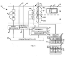
- an embodiment of an electronic toll collection system having an adaptive communication system illustrated generally by reference numeral 10.
- the electronic toll collection system may be used in a variety of applications.
- the electronic toll collection system is associated with a gated toll plaza.
- the system is associated with an open road toll processing zone.
- Other applications of the electronic toll collection system will be appreciated by those skilled in the art.
- the electronic toll collection system is applied to roadway 12 having first and second adjacent lanes 14 and 16.
- the roadway 12 may be a two lane access roadway leading towards or away from a toll highway.
- the electronic toll collection system 10 includes three roadway antennas 18A, 18B, and 18C, each of which is connected to a signal processing means, namely an Automatic Vehicle Identification ("AVI") reader 17.
- AVI Automatic Vehicle Identification
- FIG. 1 the exemplary embodiment of FIG. 1 could be modified to eliminate the midpoint antenna 18B so that only two roadway antennas 18A, 18C would be used to provide coverage to the two lanes 14 and 16.
- the antennas 18A, 18B, 18C may, in some embodiments, be mounted to an overhead gantry or other structure.
- the AVI reader 17 is a control device that processes signals that are sent and received by the roadway antennas 18A, 18B, and 18C, and includes a processor 35 and a Radio Frequency (“RF") module 24.
- RF Radio Frequency
- the RF module 24 is configured to modulate signals from the processor 35 for transmission as RF signals over the roadway antennas 18A, 18B and 18C, and to de-modulate RF signals received by the roadway antennas 18A, 18B and 18C into a form suitable for use by the processor 35.
- the AVI reader 17 employs hardware and signal processing techniques that are well known in the art.
- the processor 35 includes a programmable processing unit, volatile and non-volatile memory storing instructions and data necessary for the operation of the processor 35, and communications interfaces to permit the processor 35 to communicate with the RF module 24 and a roadside controller 30.
- the roadway antennas 18A, 18B and 18C and the AVI reader 17 function to trigger or activate a transponder 20 (shown in the windshield of vehicle 22) to record information and to acknowledge to the transponder 20 that a validated exchange has taken place. It will be appreciated by those skilled in the art that the transponder 20 may also be mounted in other locations on the vehicle 22, for example on the roof, the front grill, the license plate, etc.
- the roadway antennas 18A, 18B and 18C are directional transmit and receive antennas which, in the illustrated embodiment, have an orientation such that each of the roadway antennas 18A, 18B and 18C can only receive signals transmitted from a transponder 20 when the transponder 20 is located within a roughly elliptical coverage area associated with the antenna.
- the roadway antennas 18A, 18B and 18C are located above the roadway 12 and arranged such that they have coverage areas 26A, 26B and 26C which are aligned along an axis 28 that is orthogonal to the travel path along roadway 12.
- the major axis of the elliptical coverage areas 26A, 26B and 26C are co-linear with each other, and extend orthogonally to the direction of travel.
- the coverage area 26A provides complete coverage of the first lane 14, and the coverage area 26C provides complete coverage of the second lane 16.
- the coverage area 26B overlaps both of the coverage areas 26A and 26C.
- the coverage area 26A, 26B, 26C of each antenna 18A, 18B, 18C includes at least a portion of the roadway.
- coverage areas 26A, 26B and 26C are illustrated as having identical, perfect elliptical shapes, in reality the actual shapes of the coverage areas 26A, 26B and 26C will typically not be perfectly elliptical, but will have a shape that is dependent upon a number of factors, including RF reflections or interference caused by nearby structures, the antenna pattern and mounting orientation.
- the AVI reader 17 is connected to a roadside controller 30.
- the electronic toll collection system 10 will often include a vehicle imaging system, which is indicated generally by reference numeral 34.
- the imaging system 34 includes an image processor 42 which is connected to a number of cameras 36 arranged to cover the width of the roadway for capturing images of vehicles as they cross a camera line 38 that extends orthogonally across the roadway 12.
- the image processor 42 is connected to the roadside controller 30, and operation of the cameras 36 is synchronized by the roadside controller 30 in conjunction with a vehicle detector 40.
- the vehicle detector 40 which is connected to the roadside controller 30 detects when a vehicle has crossed a vehicle detection line 44 that extends orthogonally across the roadway 12, which is located before the camera line 38 (relative to the direction of travel).
- the output of the vehicle detector 40 is used by the roadside controller 30 to control the operation of the cameras 36.
- the vehicle detector 40 can take a number of different configurations that are well known in the art, for example it can be a device which detects the obstruction of light by an object.
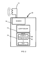
- the vehicle detection system utilizes a transponder 20 that is located in a vehicle 22 traveling on the roadway 12.
- the transponder 20 has a modem 78 that is configured to de-modulate RF signals received by a transponder antenna 72 into a form suitable for use by a transponder controller 74.
- the modem 78 is also configured to modulate signals from the transponder controller 74 for transmission as an RF signal over the transponder antenna 72.
- the transponder 20 also includes a transponder memory 76 that is connected to the transponder controller 74.
- the transponder controller 74 may access the transponder memory 76 to store and retrieve data.
- the transponder memory 76 may be random access memory (RAM) or flash memory.
- the transponder memory 76 is the integrated memory of a microcontroller.
- the transponder memory 76 is used to store configuration type data 82 for the vehicle 22 associated with the transponder 20 or for the transponder 20 itself.
- the configuration type data 82 may include data relating to the vehicle 22 and/or the transponder 20 and/or the transponder mounting.
- the configuration type data 82 may include the make and/or the model of the vehicle 22.
- the configuration type data 82 may indicate that the vehicle 22 is a HondaTM CivicTM.
- the configuration type data 82 may include data representing the class of the vehicle 22.
- the configuration type data 82 may indicate whether the vehicle 22 is an SUV, car, truck, van, mini-van, etc.
- the configuration type data 82 may also include data representing the size of the vehicle 22.
- the configuration type data 82 may indicate whether the vehicle is a compact, small, medium, or large vehicle.
- the configuration type data 82 may also include data representing the weight and/or number of axles of the vehicle 22.
- the configuration type data 82 may include data representing the type of the transponder 20, such as a model type.
- the configuration type data 82 may indicate that the transponder 20 is a 3 rd generation flat-pack model.
- the configuration type data 82 may include data representing the mounting location of the transponder 20 on the vehicle 22.
- the configuration type data 82 may indicate that the transponder 22 is mounted on the vehicle 20 windshield, license plate, front grill, roof, etc. It will be appreciated by those skilled in the art that these embodiments and examples are not exhaustive and that the configuration type data 82 may comprise other data not specifically identified in the examples above.
- the transponder memory 76 may also store other information which may be necessary for electronic toll-collection.
- the transponder memory 76 may store a unique transponder identification number 80.
- the unique transponder identification number 80 may be transmitted by the transponder 20 as a part of any of its transmissions and used by the AVI reader 17 for determining the identity of the source of the transmission.
- the AVI reader 17 may also include the unique transponder identification number 80 in any transmission originating from the antennas 18A, 18B, and 18C and destined for the transponder 20 that corresponds to the unique identification number 80.
- the communication system 10 ensures that communications which are transmitted by the antennas 18A, 18B, or 18C that are intended to be received by a specific transponder 20 are disregarded by other transponders which share the coverage areas 26A, 26B, and 26C with the transponder 20.
- the transponder 20 may be configured to cause the transponder antenna 72 to transmit at least some of the data stored in the transponder memory 76 upon the receipt of an appropriate signal from one of the roadway antennas 18A, 18B, and 18C.
- the AVI reader 17 is configured to cause the roadway antennas 18A, 18B, and 18C to periodically transmit an interrogation signal.
- the transponder controller 74 may read the contents of the transponder memory 76 and transmit at least some of the contents of the transponder memory 76 using the transponder antenna 72.
- the transponder controller 74 will be configured to cause the transponder antenna 72 to transmit all of the contents of the transponder memory 76 in response to the receipt of an interrogation signal from one of the roadway antennas 18A, 18B or 18C.
- the adaptive communication system 10 includes a system memory 50 connected to the AVI reader 17.
- the system memory 50 includes a database 52 which associates at least one predetermined communication parameter 58, 60 with various configuration types 54, 56. In some embodiments, more than one predetermined communication parameter 58, 60 may be listed for each configuration type 54, 56.
- the database 52 contains data associated with at least two types of configurations. For example, it may contain data associated with two or more vehicle 22 types and/or data associated with two or more transponder 20 types and/or data associated with two or more transponder mounting location types.
- the predetermined communication parameters 58, 60 represent variables which may be altered by the communication system 10 in order to provide a greater likelihood of a successful communication between the communication system 10 and the transponder 20.
- the predetermined communication parameters 58 and 60 include variables that have a tendency to vary for different types of vehicles, transponders and/or mounting locations.
- the predetermined communication parameter 58 or 60 represents a predetermined communication position 27 for the transponder 20 if the transponder 20 is located in a vehicle 22 of a specified type.
- the predetermined communication parameter 27 may be ten feet from one of the roadway antennas 18A, 18B or 18C if the vehicle type is a sports utility vehicle.
- the predetermined communication parameter 58 or 60 represents the transmit power level or levels of the roadway antennas 18A, 18B and 18C. In yet a further embodiment, the predetermined communication parameter 58, 60 represents the receive sensitivity or sensitivities of the roadway antennas 18A, 18B, and 18C when they are receiving transmissions from the transponder 20.
- the receive sensitivity is a measure of how faint a signal can be successfully received by the roadway antennas 18A, 18B, 18C.
- the predetermined communication parameter 58 or 60 may be an expected threshold of successful interrogation responses for use in lane assignment techniques such as those described in US Patent Number 6,219,613 and US Patent Number 7,385,525 both of which are incorporated herein by reference.
- the predetermined communication parameters 58 and 60 for various types of vehicles, transponders and/or mounting locations may be determined in a controlled test environment or may be determined by compiling data at the communications system 10 installed on the roadway 12. In either case, the predetermined communication parameters 58 and 60 may be determined by periodically adjusting a variable communication parameter and monitoring whether the adjustment has enhanced or decreased the likelihood of successful communications between the communication system 10 and the transponder 20.
- the predetermined communication position 27 for a given transponder 20 may be determined by monitoring the change in the received signal strength at the transponder 20 at various distances.
- FIG. 3 an exemplary graph is shown illustrating the signal strength of communications with transponders 20 which are located in vehicles 22 of two different types.
- a first data line 302 illustrates the signal strength of communication signals received at a transponder 20 located in a vehicle of a first type and a second data line 304 illustrates the signal strength of communication signals received at a transponder 20 located in a vehicle of a second type.
- Communications with the transponder in the vehicle of the first type have a peak signal strength at a point 308 which occurs when the transponder is between 7 and 8 feet from the antenna 18A, 18B, 18C.
- Communications with the transponder in the vehicle of the second type have a peak signal strength at a point 306 which occurs when the transponder is approximately 9 feet from the antenna 18A, 18B, 18C.
- the AVI reader 17 would then be configured to attempt to program transponders 20 that are located in vehicles of the first type when the transponder 20 is between 7 and 8 feet from the antenna 18A, 18B, 18C and to attempt to program transponders 20 that are located in vehicles of the second type when the transponder 20 is 9 feet from the antenna.
- the AVI reader 17 In operation, in response to the receipt of configuration type data 82 from the transponder 20, the AVI reader 17 is configured to determine from the database 52 the predetermined communication parameters 58, 60 corresponding to the received configuration type data 82. The AVI reader 17 is configured to subsequently adjust at least one variable communication parameter based on the predetermined communication parameters 58, 60 determined to correspond to the received configuration type data 82.
- the AVI reader 17 may contain at least one attenuator 43.
- the predetermined communication parameter 58, 60 and at least one variable communication parameter for each type 54, 56 represent the transmit power level of one or more of the antennas 18A, 18B, 18C. That is, the predetermined communication parameter 58, 60 in the database 52 is a predetermined transmit power level.
- the attenuator 43 may be used to adjust the transmit power level of one or more of the antennas based on the predetermined transmit power level in the database 52 which corresponds to the configuration type 54, 56.
- the predetermined communication parameter 58, 60 and at least one variable communication parameter for each configuration type 54, 56 may also represent an antenna receive sensitivity of one or more of the antennas 18A, 18B, 18C. That is, the predetermined communication parameter 58, 60 in the database 52 is a predetermined antenna receive sensitivity.
- the attenuator 43 may be used to adjust the antenna receive sensitivity of at least one of the antennas 18A, 18B, 18C based on the predetermined antenna receive sensitivity in the database 52 which corresponds to the configuration type 54, 56.
- the database 52 is typically indexed by configuration type 54, 56.
- the configuration type data 82 comprises data representing the make and model of the vehicle
- the database 52 may be indexed by vehicle make and/or model.
- the configuration type data 82 comprises data representing the transponder type (such as a make and/or model)
- the database 52 may be indexed by transponder type.
- the configuration type data 82 comprises data representing the transponder mount location
- the database 52 may be indexed by transponder mount location.
- the configuration type data 82 comprises data representing the size of the vehicle
- the database 52 may be indexed by vehicle size.
- the database 52 may be indexed by transponder type. In embodiments where the configuration type data 82 comprises data representing the class of the vehicle, the database 52 may be indexed by vehicle class. It will be appreciated by those skilled in the art that the indexing may be by both single parameter, e.g. vehicle type, and/or by compound parameter, e.g combination of vehicle type, transponder type and mounting location. Furthermore, it will be appreciated that the database may be indexed by other variables not specifically mentioned.
- the predetermined communication parameters 58 and 60 represent the predetermined communication position 27 of the transponder 20.
- the predetermined communication position 27 of the transponder 20 may be measured relative to the roadway antenna 18A, 18B or 18C. It will be appreciated, however, that the predetermined communication position 27 may be measured relative to other reference points. For example, the predetermined communication position 27 may be measured relative to a point of entry into the coverage area 26A, 26B, 26C upstream from the antennas 18A, 18B, 18C.
- the AVI reader 17 may contain a vehicle position tracking module for tracking the position of the transponder 20 and communicating with the transponder 20 during a time slot during which the transponder 20 is in the predetermined communication position.
- the vehicle position tracking module may use predictive algorithms in order to determine when the transponder 20 will be in the predetermined communication position 27.
- the system 10 may include a vehicle velocity determining module 41 for determining and reporting a velocity of the vehicle to the AVI reader 17.
- the vehicle velocity determining module 41 may be included in the AVI reader 17.
- the vehicle velocity determining module 41 may be implemented using the processor 35 in the AVI reader 17.
- the vehicle velocity determining module may be physically distinct from the AVI reader 17.
- the velocity of the vehicle 22 will be considered to be vehicle specific. That is, the vehicle velocity determining module 41 determines the velocity of the specific vehicle 22 carrying the transponder 20. In other embodiments, the velocity of the vehicle will not be considered to be vehicle specific and the speed of traffic will be determined based on the prevailing traffic speed of the roadway. Information regarding the speed of traffic in the roadway may be input to the vehicle velocity determining module 41 from an external source. For example, the vehicle velocity determining module 41 may receive roadway traffic speed data from an external system that measures the traffic speed. Such an external system may rely upon roadway sensors, radar guns, laser guns, or other mechanisms for determining the speed of vehicles. In another embodiment, the vehicle traffic velocity may be provided by a third-party entity, such as a municipal or regional traffic authority.
- the vehicle velocity determining module 41 determines the velocity of traffic by examining the number of times the AVI reader 17 has communicated with a vehicle 22.
- the AVI reader 17 may determine the velocity of traffic from the number of communications and a known size of the coverage areas 26A, 26B, 26C. It will be appreciated that other methods of determining the velocity of a vehicle 22 are also possible.
- the predetermined communication position 27 in the database 52 will be measured relative to the point of entry of a vehicle into the coverage areas 26A, 26B, 26C. That is, it will be at a point upstream of the antennas 18A, 18B, 18C at the periphery of the coverage area 26A, 26B, 26C.
- the AVI reader 17 may determine the time at which the AVI reader 17 first receives a response from a transponder 20 following the transmission of an interrogation signal. That is, the AVI reader 17 may determine an approximate time at which the transponder 20 enters the coverage area 26A, 26B, 26C. Using the velocity of the vehicle, the time at which the response signal is first received, and the distance from the point of entry to the predetermined communication position 27, it is possible to determine an approximate time at which the transponder 20 will be in the predetermined communication position 27 .
- the AVI reader 17 may include a signal power level sensing module for determining the signal power level of a signal transmitted by the transponder 20 and received by the roadway antennas 18A, 18B, 18C. Since the received signal strength varies with the distance between the transponder 20 and the roadway antennas 18A, 18B, 18C, the signal power level sensing module may be used to determine an approximate distance of the transponder 20 from the roadway antennas 18A, 18B or 18C. In other embodiments, the AVI reader 17 is configured to determine an approximate position of the transponder 20 based on the signal power level of signals received periodically from the transponder 20 at the antennas 18A, 18B, 18C. The AVI reader 17 is configured to determine the time slot during which the transponder 20 will be in the predetermined communication position 27 based on the approximate position of the transponder and the velocity of the vehicle 22 at the time at which the transmission from the transponder 20 was received.
- the signal strength may be measured using a signal power level sensing module connected to the roadway antennas 18A, 18B, or 18C.
- the signal strength of the signal that is transmitted by the transponder 20 in response to the interrogation signal may be measured.
- the transponder 20 may include a signal power sensing means to measure the signal strength of the interrogation signal itself. The transponder 20 may communicate the signal strength data to the communication system 10 as part of its response to the interrogation signal.
- the signal power sensing module in the AVI reader 17 or signal power sensing means in the transponder 20 may be of any type suitable for determining a signal strength level of an analog signal.
- the signal power sensing module in the AVI reader 17 or the signal power sensing means in the transponder 20 may be an analog to digital converter.
- the analog to digital converter determines a signal power level in order to determine whether a signal is above or below a threshold (and is therefore a one or a zero).
- the analog to digital converter may report the signal power level of a received signal to the processor 35.
- the signal strength may be used to approximate the distance of the vehicle 22 to the roadway antenna 18A, 18B, or 18C. That is, the signal strength will typically vary with the distance of the transponder 20 to the roadway antennas 18A, 18B, 18C.
- the memory 50 may include a distance look up table 90.
- the distance look up table 90 may be indexed by signal strength values 92, 94. For each signal strength value 92 and 94, the distance look up table 90 has a corresponding estimated distance value 96, 98 assigned. In some instances, the signal strength that is measured by the signal strength sensor may be in between the signal strength values 92, 94 in the distance look up table 90.
- a distance value may be calculated by interpolation.
- meas_sig is the measured signal strength
- high_sig is the signal strength value 92 or 94 in the distance look up table 90 which is immediately higher than the measured signal strength
- low_sig is the signal strength value 92 or 94 which is immediately lower than the measured signal strength
- high_dist is the distance value 96 or 98 corresponding to the signal strength value 92 or 94 which is immediately higher than the measured signal strength
- low_dist is the distance value 96 or 98 corresponding to the signal strength value 92 or 94 which is immediately lower than the measured signal strength.
- the distance values 96 and 98 for various signal strengths 92 and 94 are typically determined in a controlled test environment.
- FIG. 1 depicts an embodiment wherein the distance look up table 90 is implemented using the same system memory 50 as the database 52, it will be appreciated that more than one memory device may be used to implement these features.
- the AVI reader 17 receives the measured power level from the signal power level sensing module and looks up the corresponding distance value 96 or 98 in the memory.
- the AVI reader 17 may also be used to perform interpolation calculations as required and as specified above.
- the memory 50 will have more than one distance look up table 90.
- the memory 50 may have one distance look up table 90 for each of the various classes of configuration type.
- the AVI reader 17 relies on the configuration type data 82 received from the transponder 20 by one of the roadway antennas 18A, 18B, or 18C.
- the AVI reader 17 uses the distance look up table that corresponds to the configuration type data 82 to look up the distance value 96 or 98 which corresponds to the signal strength value 92 or 94.
- Free space path loss may be determined as the difference between the transmit power and the received signal power for communications between the transponder 20 and the antennas 18A, 18B, 18C.
- the AVI reader 17 may determine that the transponder 20 will be at the predetermined communication position 27 during a time slot which has already been reserved for communications with another vehicle. To ensure that the AVI reader 17 does not reserve a slot in which the transponder 20 has left the coverage area 26A, 26B, 26C, the AVI reader 17 may be configured to reserve an adjacent time slot. The AVI reader 17 may be configured to reserve an earlier adjacent time slot.
- the communication system 10 also includes a vehicle lateral position determination system for determining a lateral position of the vehicle. That is, the vehicle lateral position determination system determines which antenna 18A, 18B, 18C is most appropriate for communicating with the transponder 20. For example, in the example shown in FIG. 1 , the first antenna 18A would likely be best suited for communicating with the transponder 20 since the coverage area of the first antenna 18A best covers the path of travel of the vehicle 22. In systems which include a vehicle lateral position determination system, the AVI reader 17 may be configured to adjust the variable communication parameters for the antenna 18A, 18B, 18C that corresponds to the lateral position of the vehicle 22.
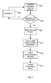
- the AVI reader 17 is configured to repeatedly perform interrogation cycles.
- the AVI reader 17 is programmed so that during each interrogation cycle all of the first to "nth" coverage areas of the communication system 10 are subsequently interrogated in time division multiplex manner.
- the roadway antennas 18A, 18B, and 18C and the AVI reader 17 will listen for a response from the transponder 20. If no response is received, an interrogation signal will be transmitted on another roadway antenna 18A, 18B, or 18C (Steps 206, 202).
- the communication system 10 may attempt to determine the lane location of the transponder 20. It will be appreciated by a person skilled in the art that, since the coverage areas 26A, 26B, and 26C of the antennas 18A, 18B and 18C may be partially overlapping, more than one antenna 18A, 18B or 18C may receive the transponder 20 response to the interrogation signal. In some embodiments, it is desirable to determine which of the antennas 18A, 18B or 18C is best suited for sending and receiving communications to the transponder 20 (Step 208).
- a vehicle lateral position determination system may be used to determine the lateral position of the vehicle 22 and/or which of the antennas 18A, 18B or 18C is best suited for communicating with the transponder 20.
- Various methods are known for determining which antenna is best suited for transmission. In many of these methods the communication system 10 will only attempt to determine the lane position of the vehicle 22 after a number of handshakes between the transponder 20 and the communication system 10.
- the signal power level sensing module may be used to determine which roadway antenna 18A, 18B, or 18C is receiving the strongest communication signal from the transponder 20.
- the preferred antenna roadway 18A, 18B, or 18C for transmitting signals to the transponder 20 will be the roadway antenna 18A, 18B, or 18C which has received the strongest communication signal from the transponder 20.
- the response to the interrogation signal typically includes the data stored in the transponder memory 76 including the transponder identification number 80 and the configuration type data 82.
- the configuration type data 82 in the transponder memory 76 corresponds to one of the various configuration types 54 or 56 in the memory 50 of the communication system 10.
- the communication system 10 looks up the predetermined communication parameter 58 or 60 that corresponds to the configuration type data 82 in the memory 50 of the communication system 10.
- more than one communication parameter corresponds to each configuration type 54 or 56.
- each configuration type may have a predetermined communication parameter representing the receiver sensitivity level, and another predetermined communication parameter representing the transmit power level.
- the AVI reader 17 adjusts variable communication parameters of the communication system 10 using the predetermined communication parameters 58 or 60.
- the predetermined communication parameters, 58 or 60 represent the transmit power level
- the attenuators 43 may be used to adjust the power level of the roadway antennas 18A, 18B, and 18C.
- the predetermined communication parameters 58 or 60 represent the receiver sensitivity of the roadway antennas 18A, 18B, or 18C
- attenuators 43 may be used to adjust the sensitivity of one or more of the antennas 18A, 18B, and 18C.
- the adjustment may be made to all antennas 18A, 18B, 18C and that, in other embodiments, the adjustment is only made to a subset of all available antennas 18A, 18B, or 18C. For example, in some embodiments, the adjustment is only made to one antenna.
- variable communication parameter is only adjusted for one roadway antenna 18A, 18B, or 18C.
- variable communication parameter may only be adjusted for the roadway antenna 18A, 18B, or 18C which is determined at step 208 to be best suited for communicating with the transponder 20 due to the lane position of the vehicle 22.
- the method will include a step of updating data in the transponder.
- This data may be a record of passage, to be retrieved at a subsequent toll location to be used to compute the toll fee.
- This data may also be commands to activate the audio & visual indicators on the transponder.
- the communication system 10 may transmit a programming signal to the transponder 20.
- the programming signal may include, for example, the current plaza and lane number to be stored to the transponder memory 76.
- the communication system 10 is used to transmit a programming signal to the transponder 20 using at least one of the roadway antennas 18A, 18B or 18C.
- the communication system 10 may transmit the programming signal to the transponder 20 using the roadway antenna 18A, 18B or 18C that is selected at step 208 to be best suited for communicating with the transponder 20.
- the transponder 20 Upon receipt of the programming signal by the transponder 20, the transponder 20 will program at least some of the data embedded in the programming signal to the transponder memory 76.
- the predetermined communication parameter 58 or 60 is a predetermined communication position 27 for the transponder 20.
- the predetermined communication position 27 for the transponder 20 is the position at which the transponder 20 in the vehicle 22 is at a distance from the roadway antennas 18A, 18B, or 18C which will maximize the likelihood of successful communications between the roadway antennas 18A, 18B, or 18C and the transponder 20.
- the predetermined communication position 27 will vary based on the type of the vehicle 22.
- the method wherein the predetermined communication parameter 58 or 60 is the predetermined communication position 27 for the transponder 20 is similar to the method discussed above where the predetermined communication parameter 58 or 60 is the transmit power level of the roadway antennas 18A, 18B, and 18C or the receive sensitivity of the roadway antennas 18A, 18B, 18C.
- the predetermined communication parameter 58 or 60 is the predetermined communication position 27 for the transponder 20
- the communication system 10 measures the speed of the vehicle 22 carrying the transponder 20.
- the AVI reader 17 adjusts variable communication parameters of the communication system 10 using the predetermined communication parameters 58 or 60.
- the AVI reader 17 calculates a time slot during which the communication system 10 may attempt to program the transponder 20.
- the AVI reader 17 calculates the time period after which the transponder will be in the predetermined communication position 27 using the vehicle velocity and the distance value which was determined using the measured signal strength and the distance look up table 90.
- d2 is the distance of the transponder 20 from the antennas 18A, 18B, 18C when the signal strength was measured, as determined by the distance look up table 90
- d1 is the predetermined communication position 27 of the transponder
- v is the velocity of the vehicle.
- other predictive algorithms may also be used.
- the time calculations will be performed using the measured signal strength which is the greatest. In other embodiments, the time calculations will be performed using the signal strength that is measured at the roadway antenna 18A, 18B, or 18C which was selected at step 208 to be the best antenna for communicating with the transponder 20 due to the lane position of the transponder 20.
- the AVI reader 17 After the AVI reader 17 has calculated the time at which the transponder 20 in the vehicle 22 will likely be in the predetermined communication position 27, it reserves a time slot with the roadway antenna 18A, 18B or 18C which was determined at step 208 to be the most suitable antenna for communicating with the transponder 20. If the desired time slot is already reserved, the AVI reader 17 may be configured to select the nearest unreserved time slot for that roadway antenna 18A, 18B or 18C.
- the AVI reader 17 is illustrated as being implemented as a single unit, the components that make up the AVI reader 17 may be physically separated.
- the attenuator 43 may be mounted on the gantry in close proximity to the antennas 18A, 18B, 18C.
Landscapes
- Engineering & Computer Science (AREA)
- Computer Networks & Wireless Communication (AREA)
- Business, Economics & Management (AREA)
- Finance (AREA)
- Physics & Mathematics (AREA)
- General Physics & Mathematics (AREA)
- Traffic Control Systems (AREA)
- Devices For Checking Fares Or Tickets At Control Points (AREA)
- Mobile Radio Communication Systems (AREA)
Priority Applications (2)
| Application Number | Priority Date | Filing Date | Title |
|---|---|---|---|
| SI201031116T SI2409409T1 (sl) | 2009-03-20 | 2010-03-22 | Adaptivna komunikacija v sistemu elektronskega cestninjenja |
| PL10753033T PL2409409T3 (pl) | 2009-03-20 | 2010-03-22 | Sposób adaptacyjnej komunikacji w elektronicznym systemie poboru opłat drogowych |
Applications Claiming Priority (2)
| Application Number | Priority Date | Filing Date | Title |
|---|---|---|---|
| US16185909P | 2009-03-20 | 2009-03-20 | |
| PCT/CA2010/000384 WO2010105349A1 (en) | 2009-03-20 | 2010-03-22 | Adaptive communication in an electronic toll collection system |
Publications (3)
| Publication Number | Publication Date |
|---|---|
| EP2409409A1 EP2409409A1 (en) | 2012-01-25 |
| EP2409409A4 EP2409409A4 (en) | 2013-11-06 |
| EP2409409B1 true EP2409409B1 (en) | 2015-11-11 |
Family
ID=42737048
Family Applications (1)
| Application Number | Title | Priority Date | Filing Date |
|---|---|---|---|
| EP10753033.9A Active EP2409409B1 (en) | 2009-03-20 | 2010-03-22 | Adaptive communication in an electronic toll collection system |
Country Status (8)
| Country | Link |
|---|---|
| US (1) | US8508341B2 (pl) |
| EP (1) | EP2409409B1 (pl) |
| DK (1) | DK2409409T3 (pl) |
| ES (1) | ES2560558T3 (pl) |
| PL (1) | PL2409409T3 (pl) |
| PT (1) | PT2409409E (pl) |
| SI (1) | SI2409409T1 (pl) |
| WO (1) | WO2010105349A1 (pl) |
Families Citing this family (37)
| Publication number | Priority date | Publication date | Assignee | Title |
|---|---|---|---|---|
| US20110307305A1 (en) * | 2010-06-14 | 2011-12-15 | Japjeev Kohli | Multi-protocol electronic toll collection system |
| EP2625886B1 (en) * | 2010-10-05 | 2016-12-07 | UTC Fire & Security Corporation | Bi-directional link margin establishment for wireless embedded systems |
| CA2744625C (en) | 2011-06-28 | 2018-02-06 | Kapsch Trafficcom Ag | Rf-link margin measurement method and system |
| CN102622784B (zh) * | 2012-03-29 | 2014-03-05 | 北京速通科技有限公司 | 利用正交相控阵天线实现多车道自由流电子收费的方法 |
| CN105205872A (zh) * | 2012-12-27 | 2015-12-30 | 深圳市金溢科技股份有限公司 | 唤醒模块、车载单元及唤醒车载单元的方法 |
| DK2840554T3 (en) * | 2013-08-23 | 2016-09-12 | Kapsch Trafficcom Ag | METHOD AND RADIO FIRE FOR LOCATION OF AN ONBOARD DEVICE |
| CA2824703C (en) * | 2013-08-26 | 2021-03-16 | Alastair Malarky | Methods and systems for determining vehicle position in an automatic vehicle identification system |
| CA2824704A1 (en) * | 2013-08-26 | 2015-02-26 | Alastair Malarky | Methods and systems for determining a range rate for a backscatter transponder |
| US9754171B1 (en) | 2014-06-27 | 2017-09-05 | Blinker, Inc. | Method and apparatus for receiving vehicle information from an image and posting the vehicle information to a website |
| US10867327B1 (en) | 2014-06-27 | 2020-12-15 | Blinker, Inc. | System and method for electronic processing of vehicle transactions based on image detection of vehicle license plate |
| US10515285B2 (en) | 2014-06-27 | 2019-12-24 | Blinker, Inc. | Method and apparatus for blocking information from an image |
| US9600733B1 (en) | 2014-06-27 | 2017-03-21 | Blinker, Inc. | Method and apparatus for receiving car parts data from an image |
| US9563814B1 (en) | 2014-06-27 | 2017-02-07 | Blinker, Inc. | Method and apparatus for recovering a vehicle identification number from an image |
| US9558419B1 (en) | 2014-06-27 | 2017-01-31 | Blinker, Inc. | Method and apparatus for receiving a location of a vehicle service center from an image |
| US9779318B1 (en) | 2014-06-27 | 2017-10-03 | Blinker, Inc. | Method and apparatus for verifying vehicle ownership from an image |
| US9760776B1 (en) | 2014-06-27 | 2017-09-12 | Blinker, Inc. | Method and apparatus for obtaining a vehicle history report from an image |
| US10540564B2 (en) | 2014-06-27 | 2020-01-21 | Blinker, Inc. | Method and apparatus for identifying vehicle information from an image |
| US9589202B1 (en) | 2014-06-27 | 2017-03-07 | Blinker, Inc. | Method and apparatus for receiving an insurance quote from an image |
| US10733471B1 (en) | 2014-06-27 | 2020-08-04 | Blinker, Inc. | Method and apparatus for receiving recall information from an image |
| US9818154B1 (en) | 2014-06-27 | 2017-11-14 | Blinker, Inc. | System and method for electronic processing of vehicle transactions based on image detection of vehicle license plate |
| US10572758B1 (en) | 2014-06-27 | 2020-02-25 | Blinker, Inc. | Method and apparatus for receiving a financing offer from an image |
| US9607236B1 (en) | 2014-06-27 | 2017-03-28 | Blinker, Inc. | Method and apparatus for providing loan verification from an image |
| US9773184B1 (en) | 2014-06-27 | 2017-09-26 | Blinker, Inc. | Method and apparatus for receiving a broadcast radio service offer from an image |
| US10579892B1 (en) | 2014-06-27 | 2020-03-03 | Blinker, Inc. | Method and apparatus for recovering license plate information from an image |
| US9594971B1 (en) | 2014-06-27 | 2017-03-14 | Blinker, Inc. | Method and apparatus for receiving listings of similar vehicles from an image |
| US9892337B1 (en) | 2014-06-27 | 2018-02-13 | Blinker, Inc. | Method and apparatus for receiving a refinancing offer from an image |
| US9589201B1 (en) | 2014-06-27 | 2017-03-07 | Blinker, Inc. | Method and apparatus for recovering a vehicle value from an image |
| JP6543857B2 (ja) * | 2015-11-30 | 2019-07-17 | 三菱重工機械システム株式会社 | 通信制御装置、料金収受システム、通信制御方法及びプログラム |
| EP3261060B1 (de) * | 2016-06-24 | 2021-08-04 | Skidata Ag | Verfahren zur zugangskontrolle bei einem zugangskontrollsystem für personen oder fahrzeuge sowie zugangskontrollsystem |
| EP3301653B1 (en) | 2016-09-29 | 2020-04-29 | Kapsch TrafficCom AG | Method for calibrating an onboard unit, system, and onboard unit therefor |
| SE542649C2 (en) | 2017-06-28 | 2020-06-23 | Tagmaster Ab | Method and system for remotely detecting a vehicle |
| US11158136B2 (en) * | 2019-07-30 | 2021-10-26 | Electronic Transaction Consultants Corp. | Tolling system using vehicle identifier correlation |
| US11615650B2 (en) * | 2020-02-12 | 2023-03-28 | Electronic Transaction Consultants, Llc | Tolling system using both fully and limited equipped detection systems |
| CN111325864A (zh) * | 2020-03-27 | 2020-06-23 | 深圳复芯微科技有限公司 | 车载单元接收灵敏度的控制方法、装置及设备 |
| CN115131890B (zh) * | 2021-03-26 | 2024-12-10 | 深圳引望智能技术有限公司 | 通行控制方法及装置 |
| CN113706731A (zh) * | 2021-07-15 | 2021-11-26 | 北京无限感测科技有限公司 | 一种etc集成天线功率自适应调整方法和装置 |
| EP4213509B1 (en) * | 2022-01-18 | 2025-11-26 | Kapsch TrafficCom AG | Method and apparatus for determining a lateral vehicle position |
Family Cites Families (8)
| Publication number | Priority date | Publication date | Assignee | Title |
|---|---|---|---|---|
| US5086389A (en) * | 1990-05-17 | 1992-02-04 | Hassett John J | Automatic toll processing apparatus |
| EP1240034B1 (en) | 1999-12-15 | 2003-07-02 | The Goodyear Tire & Rubber Company | An rf transponder comprising a programmable trimmer and method of trimming operating characteristics of an rf transponder |
| JP3903695B2 (ja) | 2000-07-12 | 2007-04-11 | 株式会社日立製作所 | マルチアプリケーション対応デジタル無線通信システム、その基地局及び移動局 |
| US7545287B2 (en) * | 2004-08-31 | 2009-06-09 | Raytheon Company | Enforcement transponder |
| US7233260B2 (en) * | 2004-10-05 | 2007-06-19 | Mark Iv Industries Corp. | Electronic toll collection system |
| US7385525B2 (en) * | 2005-07-07 | 2008-06-10 | Mark Iv Industries Corporation | Dynamic timing adjustment in an electronic toll collection system |
| CA2560398C (en) * | 2005-09-21 | 2015-06-16 | Mark Iv Industries Corp. | Transceiver redundancy in an electronic toll collection system |
| US8106753B2 (en) * | 2008-08-27 | 2012-01-31 | The Boeing Company | Determining and providing vehicle conditions and capabilities |
-
2010
- 2010-03-19 US US12/727,964 patent/US8508341B2/en active Active
- 2010-03-22 WO PCT/CA2010/000384 patent/WO2010105349A1/en not_active Ceased
- 2010-03-22 PL PL10753033T patent/PL2409409T3/pl unknown
- 2010-03-22 EP EP10753033.9A patent/EP2409409B1/en active Active
- 2010-03-22 SI SI201031116T patent/SI2409409T1/sl unknown
- 2010-03-22 ES ES10753033.9T patent/ES2560558T3/es active Active
- 2010-03-22 DK DK10753033.9T patent/DK2409409T3/en active
- 2010-03-22 PT PT107530339T patent/PT2409409E/pt unknown
Also Published As
| Publication number | Publication date |
|---|---|
| EP2409409A4 (en) | 2013-11-06 |
| EP2409409A1 (en) | 2012-01-25 |
| US8508341B2 (en) | 2013-08-13 |
| DK2409409T3 (en) | 2016-02-15 |
| ES2560558T3 (es) | 2016-02-19 |
| WO2010105349A1 (en) | 2010-09-23 |
| WO2010105349A8 (en) | 2011-11-24 |
| US20100237998A1 (en) | 2010-09-23 |
| PT2409409E (pt) | 2016-02-29 |
| PL2409409T3 (pl) | 2016-05-31 |
| SI2409409T1 (sl) | 2016-03-31 |
Similar Documents
| Publication | Publication Date | Title |
|---|---|---|
| EP2409409B1 (en) | Adaptive communication in an electronic toll collection system | |
| US9019151B2 (en) | Method and device for determining the distance between a radio beacon and an onboard unit | |
| US8730066B2 (en) | Real-time vehicle position determination using communications with variable latency | |
| US8228205B2 (en) | Vehicle lane discrimination in an electronic toll collection system | |
| EP0802515B1 (en) | Vehicle identification system for electric toll collection system | |
| EP2541503B1 (en) | Rf-link margin measurement method and system | |
| WO2008055338A1 (en) | Monopulse traffic sensor and method | |
| EP4071499A1 (en) | Method for radar interference mitigation with cooperative rules | |
| EP3965067A1 (en) | Vehicle detection | |
| US20220326344A1 (en) | Methods for Radar Interference Mitigation with Broadcasting Center | |
| CN111951417A (zh) | 一种多路侧单元信号同步发送方法及装置 | |
| CN111105509B (zh) | 基于毫米波雷达的etc车辆检测方法、系统及存储介质 | |
| CN118433690B (zh) | 一种针对etc交易的数据传输方法、装置及电子设备 | |
| KR100875564B1 (ko) | 근거리 물체 감지 시스템 | |
| EP3301653B1 (en) | Method for calibrating an onboard unit, system, and onboard unit therefor | |
| JPH08223080A (ja) | 車両用通信装置 | |
| Koelmeyer et al. | Tagless tolling using dsrc for intelligent transport system: An interference study | |
| EP4213509B1 (en) | Method and apparatus for determining a lateral vehicle position | |
| JP4127584B2 (ja) | 交通量計測システムと交通量計測システムの交通量計測方法 | |
| JP4060542B2 (ja) | 路側無線装置、車載装置および無線通信方法 | |
| JP2004199586A (ja) | 自動料金収受システム及び車載機 | |
| JP2000030101A (ja) | ノンストップ自動料金収受システム |
Legal Events
| Date | Code | Title | Description |
|---|---|---|---|
| PUAI | Public reference made under article 153(3) epc to a published international application that has entered the european phase |
Free format text: ORIGINAL CODE: 0009012 |
|
| 17P | Request for examination filed |
Effective date: 20110929 |
|
| AK | Designated contracting states |
Kind code of ref document: A1 Designated state(s): AT BE BG CH CY CZ DE DK EE ES FI FR GB GR HR HU IE IS IT LI LT LU LV MC MK MT NL NO PL PT RO SE SI SK SM TR |
|
| RAP1 | Party data changed (applicant data changed or rights of an application transferred) |
Owner name: KAPSCH TRAFFICCOM AG |
|
| DAX | Request for extension of the european patent (deleted) | ||
| A4 | Supplementary search report drawn up and despatched |
Effective date: 20131009 |
|
| RIC1 | Information provided on ipc code assigned before grant |
Ipc: G07B 15/06 20110101ALI20131002BHEP Ipc: H04B 1/59 20060101AFI20131002BHEP Ipc: G07B 15/00 20110101ALI20131002BHEP |
|
| 17Q | First examination report despatched |
Effective date: 20140910 |
|
| GRAP | Despatch of communication of intention to grant a patent |
Free format text: ORIGINAL CODE: EPIDOSNIGR1 |
|
| INTG | Intention to grant announced |
Effective date: 20150612 |
|
| GRAS | Grant fee paid |
Free format text: ORIGINAL CODE: EPIDOSNIGR3 |
|
| GRAA | (expected) grant |
Free format text: ORIGINAL CODE: 0009210 |
|
| AK | Designated contracting states |
Kind code of ref document: B1 Designated state(s): AT BE BG CH CY CZ DE DK EE ES FI FR GB GR HR HU IE IS IT LI LT LU LV MC MK MT NL NO PL PT RO SE SI SK SM TR |
|
| REG | Reference to a national code |
Ref country code: GB Ref legal event code: FG4D |
|
| REG | Reference to a national code |
Ref country code: CH Ref legal event code: EP |
|
| REG | Reference to a national code |
Ref country code: IE Ref legal event code: FG4D |
|
| REG | Reference to a national code |
Ref country code: AT Ref legal event code: REF Ref document number: 760901 Country of ref document: AT Kind code of ref document: T Effective date: 20151215 |
|
| REG | Reference to a national code |
Ref country code: DE Ref legal event code: R096 Ref document number: 602010029010 Country of ref document: DE |
|
| REG | Reference to a national code |
Ref country code: DK Ref legal event code: T3 Effective date: 20160212 |
|
| REG | Reference to a national code |
Ref country code: ES Ref legal event code: FG2A Ref document number: 2560558 Country of ref document: ES Kind code of ref document: T3 Effective date: 20160219 |
|
| REG | Reference to a national code |
Ref country code: SE Ref legal event code: TRGR |
|
| REG | Reference to a national code |
Ref country code: PT Ref legal event code: SC4A Free format text: AVAILABILITY OF NATIONAL TRANSLATION Effective date: 20160125 |
|
| REG | Reference to a national code |
Ref country code: LT Ref legal event code: MG4D |
|
| REG | Reference to a national code |
Ref country code: NO Ref legal event code: T2 Effective date: 20151111 Ref country code: FR Ref legal event code: PLFP Year of fee payment: 7 |
|
| REG | Reference to a national code |
Ref country code: NL Ref legal event code: FP |
|
| PG25 | Lapsed in a contracting state [announced via postgrant information from national office to epo] |
Ref country code: LT Free format text: LAPSE BECAUSE OF FAILURE TO SUBMIT A TRANSLATION OF THE DESCRIPTION OR TO PAY THE FEE WITHIN THE PRESCRIBED TIME-LIMIT Effective date: 20151111 Ref country code: IS Free format text: LAPSE BECAUSE OF FAILURE TO SUBMIT A TRANSLATION OF THE DESCRIPTION OR TO PAY THE FEE WITHIN THE PRESCRIBED TIME-LIMIT Effective date: 20160311 Ref country code: HR Free format text: LAPSE BECAUSE OF FAILURE TO SUBMIT A TRANSLATION OF THE DESCRIPTION OR TO PAY THE FEE WITHIN THE PRESCRIBED TIME-LIMIT Effective date: 20151111 |
|
| PG25 | Lapsed in a contracting state [announced via postgrant information from national office to epo] |
Ref country code: GR Free format text: LAPSE BECAUSE OF FAILURE TO SUBMIT A TRANSLATION OF THE DESCRIPTION OR TO PAY THE FEE WITHIN THE PRESCRIBED TIME-LIMIT Effective date: 20160212 Ref country code: LV Free format text: LAPSE BECAUSE OF FAILURE TO SUBMIT A TRANSLATION OF THE DESCRIPTION OR TO PAY THE FEE WITHIN THE PRESCRIBED TIME-LIMIT Effective date: 20151111 Ref country code: FI Free format text: LAPSE BECAUSE OF FAILURE TO SUBMIT A TRANSLATION OF THE DESCRIPTION OR TO PAY THE FEE WITHIN THE PRESCRIBED TIME-LIMIT Effective date: 20151111 |
|
| REG | Reference to a national code |
Ref country code: SK Ref legal event code: T3 Ref document number: E 20536 Country of ref document: SK |
|
| REG | Reference to a national code |
Ref country code: DE Ref legal event code: R097 Ref document number: 602010029010 Country of ref document: DE |
|
| PG25 | Lapsed in a contracting state [announced via postgrant information from national office to epo] |
Ref country code: BE Free format text: LAPSE BECAUSE OF NON-PAYMENT OF DUE FEES Effective date: 20160331 Ref country code: EE Free format text: LAPSE BECAUSE OF FAILURE TO SUBMIT A TRANSLATION OF THE DESCRIPTION OR TO PAY THE FEE WITHIN THE PRESCRIBED TIME-LIMIT Effective date: 20151111 Ref country code: RO Free format text: LAPSE BECAUSE OF FAILURE TO SUBMIT A TRANSLATION OF THE DESCRIPTION OR TO PAY THE FEE WITHIN THE PRESCRIBED TIME-LIMIT Effective date: 20151111 Ref country code: SM Free format text: LAPSE BECAUSE OF FAILURE TO SUBMIT A TRANSLATION OF THE DESCRIPTION OR TO PAY THE FEE WITHIN THE PRESCRIBED TIME-LIMIT Effective date: 20151111 |
|
| PLBE | No opposition filed within time limit |
Free format text: ORIGINAL CODE: 0009261 |
|
| STAA | Information on the status of an ep patent application or granted ep patent |
Free format text: STATUS: NO OPPOSITION FILED WITHIN TIME LIMIT |
|
| 26N | No opposition filed |
Effective date: 20160812 |
|
| PG25 | Lapsed in a contracting state [announced via postgrant information from national office to epo] |
Ref country code: LU Free format text: LAPSE BECAUSE OF FAILURE TO SUBMIT A TRANSLATION OF THE DESCRIPTION OR TO PAY THE FEE WITHIN THE PRESCRIBED TIME-LIMIT Effective date: 20160322 Ref country code: MC Free format text: LAPSE BECAUSE OF FAILURE TO SUBMIT A TRANSLATION OF THE DESCRIPTION OR TO PAY THE FEE WITHIN THE PRESCRIBED TIME-LIMIT Effective date: 20151111 |
|
| REG | Reference to a national code |
Ref country code: IE Ref legal event code: MM4A |
|
| PG25 | Lapsed in a contracting state [announced via postgrant information from national office to epo] |
Ref country code: BE Free format text: LAPSE BECAUSE OF FAILURE TO SUBMIT A TRANSLATION OF THE DESCRIPTION OR TO PAY THE FEE WITHIN THE PRESCRIBED TIME-LIMIT Effective date: 20151111 |
|
| PG25 | Lapsed in a contracting state [announced via postgrant information from national office to epo] |
Ref country code: IE Free format text: LAPSE BECAUSE OF NON-PAYMENT OF DUE FEES Effective date: 20160322 |
|
| REG | Reference to a national code |
Ref country code: FR Ref legal event code: PLFP Year of fee payment: 8 |
|
| PG25 | Lapsed in a contracting state [announced via postgrant information from national office to epo] |
Ref country code: MT Free format text: LAPSE BECAUSE OF FAILURE TO SUBMIT A TRANSLATION OF THE DESCRIPTION OR TO PAY THE FEE WITHIN THE PRESCRIBED TIME-LIMIT Effective date: 20151111 |
|
| REG | Reference to a national code |
Ref country code: FR Ref legal event code: PLFP Year of fee payment: 9 |
|
| PG25 | Lapsed in a contracting state [announced via postgrant information from national office to epo] |
Ref country code: CY Free format text: LAPSE BECAUSE OF FAILURE TO SUBMIT A TRANSLATION OF THE DESCRIPTION OR TO PAY THE FEE WITHIN THE PRESCRIBED TIME-LIMIT Effective date: 20151111 Ref country code: HU Free format text: LAPSE BECAUSE OF FAILURE TO SUBMIT A TRANSLATION OF THE DESCRIPTION OR TO PAY THE FEE WITHIN THE PRESCRIBED TIME-LIMIT; INVALID AB INITIO Effective date: 20100322 |
|
| PG25 | Lapsed in a contracting state [announced via postgrant information from national office to epo] |
Ref country code: MT Free format text: LAPSE BECAUSE OF FAILURE TO SUBMIT A TRANSLATION OF THE DESCRIPTION OR TO PAY THE FEE WITHIN THE PRESCRIBED TIME-LIMIT Effective date: 20160331 Ref country code: TR Free format text: LAPSE BECAUSE OF FAILURE TO SUBMIT A TRANSLATION OF THE DESCRIPTION OR TO PAY THE FEE WITHIN THE PRESCRIBED TIME-LIMIT Effective date: 20151111 Ref country code: MK Free format text: LAPSE BECAUSE OF FAILURE TO SUBMIT A TRANSLATION OF THE DESCRIPTION OR TO PAY THE FEE WITHIN THE PRESCRIBED TIME-LIMIT Effective date: 20151111 |
|
| PG25 | Lapsed in a contracting state [announced via postgrant information from national office to epo] |
Ref country code: BG Free format text: LAPSE BECAUSE OF FAILURE TO SUBMIT A TRANSLATION OF THE DESCRIPTION OR TO PAY THE FEE WITHIN THE PRESCRIBED TIME-LIMIT Effective date: 20151111 |
|
| REG | Reference to a national code |
Ref country code: AT Ref legal event code: UEP Ref document number: 760901 Country of ref document: AT Kind code of ref document: T Effective date: 20151111 |
|
| PGFP | Annual fee paid to national office [announced via postgrant information from national office to epo] |
Ref country code: DK Payment date: 20200324 Year of fee payment: 11 Ref country code: NL Payment date: 20200319 Year of fee payment: 11 Ref country code: PT Payment date: 20200221 Year of fee payment: 11 Ref country code: GB Payment date: 20200323 Year of fee payment: 11 Ref country code: PL Payment date: 20200305 Year of fee payment: 11 Ref country code: NO Payment date: 20200326 Year of fee payment: 11 |
|
| PGFP | Annual fee paid to national office [announced via postgrant information from national office to epo] |
Ref country code: SI Payment date: 20200221 Year of fee payment: 11 Ref country code: CZ Payment date: 20200318 Year of fee payment: 11 Ref country code: SK Payment date: 20200318 Year of fee payment: 11 Ref country code: CH Payment date: 20200319 Year of fee payment: 11 |
|
| PGFP | Annual fee paid to national office [announced via postgrant information from national office to epo] |
Ref country code: IT Payment date: 20200318 Year of fee payment: 11 |
|
| REG | Reference to a national code |
Ref country code: NO Ref legal event code: MMEP |
|
| PG25 | Lapsed in a contracting state [announced via postgrant information from national office to epo] |
Ref country code: CZ Free format text: LAPSE BECAUSE OF NON-PAYMENT OF DUE FEES Effective date: 20210322 |
|
| REG | Reference to a national code |
Ref country code: CH Ref legal event code: PL |
|
| REG | Reference to a national code |
Ref country code: DK Ref legal event code: EBP Effective date: 20210331 |
|
| REG | Reference to a national code |
Ref country code: NL Ref legal event code: MM Effective date: 20210401 |
|
| GBPC | Gb: european patent ceased through non-payment of renewal fee |
Effective date: 20210322 |
|
| REG | Reference to a national code |
Ref country code: SK Ref legal event code: MM4A Ref document number: E 20536 Country of ref document: SK Effective date: 20210322 |
|
| PG25 | Lapsed in a contracting state [announced via postgrant information from national office to epo] |
Ref country code: PT Free format text: LAPSE BECAUSE OF NON-PAYMENT OF DUE FEES Effective date: 20210922 |
|
| PG25 | Lapsed in a contracting state [announced via postgrant information from national office to epo] |
Ref country code: GB Free format text: LAPSE BECAUSE OF NON-PAYMENT OF DUE FEES Effective date: 20210322 Ref country code: SK Free format text: LAPSE BECAUSE OF NON-PAYMENT OF DUE FEES Effective date: 20210322 Ref country code: NL Free format text: LAPSE BECAUSE OF NON-PAYMENT OF DUE FEES Effective date: 20210401 Ref country code: NO Free format text: LAPSE BECAUSE OF NON-PAYMENT OF DUE FEES Effective date: 20210331 Ref country code: LI Free format text: LAPSE BECAUSE OF NON-PAYMENT OF DUE FEES Effective date: 20210331 Ref country code: CH Free format text: LAPSE BECAUSE OF NON-PAYMENT OF DUE FEES Effective date: 20210331 |
|
| REG | Reference to a national code |
Ref country code: SI Ref legal event code: KO00 Effective date: 20211129 |
|
| PG25 | Lapsed in a contracting state [announced via postgrant information from national office to epo] |
Ref country code: SI Free format text: LAPSE BECAUSE OF NON-PAYMENT OF DUE FEES Effective date: 20210323 |
|
| PG25 | Lapsed in a contracting state [announced via postgrant information from national office to epo] |
Ref country code: IT Free format text: LAPSE BECAUSE OF NON-PAYMENT OF DUE FEES Effective date: 20210322 Ref country code: DK Free format text: LAPSE BECAUSE OF NON-PAYMENT OF DUE FEES Effective date: 20210331 |
|
| PG25 | Lapsed in a contracting state [announced via postgrant information from national office to epo] |
Ref country code: PL Free format text: LAPSE BECAUSE OF NON-PAYMENT OF DUE FEES Effective date: 20210322 |
|
| P01 | Opt-out of the competence of the unified patent court (upc) registered |
Effective date: 20230513 |
|
| PGFP | Annual fee paid to national office [announced via postgrant information from national office to epo] |
Ref country code: SE Payment date: 20250321 Year of fee payment: 16 |
|
| PGFP | Annual fee paid to national office [announced via postgrant information from national office to epo] |
Ref country code: DE Payment date: 20250319 Year of fee payment: 16 |
|
| PGFP | Annual fee paid to national office [announced via postgrant information from national office to epo] |
Ref country code: AT Payment date: 20250320 Year of fee payment: 16 |
|
| PGFP | Annual fee paid to national office [announced via postgrant information from national office to epo] |
Ref country code: FR Payment date: 20250325 Year of fee payment: 16 |
|
| PGFP | Annual fee paid to national office [announced via postgrant information from national office to epo] |
Ref country code: ES Payment date: 20250425 Year of fee payment: 16 |