EP2409134B1 - Detektor für doppelbrechende objekte - Google Patents
Detektor für doppelbrechende objekte Download PDFInfo
- Publication number
- EP2409134B1 EP2409134B1 EP10710907.6A EP10710907A EP2409134B1 EP 2409134 B1 EP2409134 B1 EP 2409134B1 EP 10710907 A EP10710907 A EP 10710907A EP 2409134 B1 EP2409134 B1 EP 2409134B1
- Authority
- EP
- European Patent Office
- Prior art keywords
- hair
- polarization state
- optical radiation
- source
- skin surface
- Prior art date
- Legal status (The legal status is an assumption and is not a legal conclusion. Google has not performed a legal analysis and makes no representation as to the accuracy of the status listed.)
- Active
Links
- 230000010287 polarization Effects 0.000 claims description 136
- 210000004209 hair Anatomy 0.000 claims description 108
- 230000003287 optical effect Effects 0.000 claims description 86
- 230000005855 radiation Effects 0.000 claims description 67
- 238000001514 detection method Methods 0.000 claims description 30
- 238000003384 imaging method Methods 0.000 claims description 26
- 241001465754 Metazoa Species 0.000 claims description 10
- 230000001131 transforming effect Effects 0.000 claims description 3
- 230000009466 transformation Effects 0.000 claims description 2
- 230000008859 change Effects 0.000 description 10
- 238000000034 method Methods 0.000 description 10
- 230000003695 hair diameter Effects 0.000 description 7
- 238000001218 confocal laser scanning microscopy Methods 0.000 description 6
- 230000008569 process Effects 0.000 description 6
- 230000003595 spectral effect Effects 0.000 description 5
- 239000012530 fluid Substances 0.000 description 4
- 238000007654 immersion Methods 0.000 description 4
- 238000001228 spectrum Methods 0.000 description 4
- 206010040880 Skin irritation Diseases 0.000 description 2
- 230000001419 dependent effect Effects 0.000 description 2
- 230000005684 electric field Effects 0.000 description 2
- 238000005265 energy consumption Methods 0.000 description 2
- 239000011521 glass Substances 0.000 description 2
- 238000002347 injection Methods 0.000 description 2
- 239000007924 injection Substances 0.000 description 2
- 238000005259 measurement Methods 0.000 description 2
- 230000036556 skin irritation Effects 0.000 description 2
- 231100000475 skin irritation Toxicity 0.000 description 2
- XLYOFNOQVPJJNP-UHFFFAOYSA-N water Substances O XLYOFNOQVPJJNP-UHFFFAOYSA-N 0.000 description 2
- 101100028791 Caenorhabditis elegans pbs-5 gene Proteins 0.000 description 1
- 206010013786 Dry skin Diseases 0.000 description 1
- 238000010521 absorption reaction Methods 0.000 description 1
- 239000003570 air Substances 0.000 description 1
- 230000015556 catabolic process Effects 0.000 description 1
- 230000001427 coherent effect Effects 0.000 description 1
- 230000023077 detection of light stimulus Effects 0.000 description 1
- 230000037336 dry skin Effects 0.000 description 1
- 238000005401 electroluminescence Methods 0.000 description 1
- 238000005516 engineering process Methods 0.000 description 1
- 230000001747 exhibiting effect Effects 0.000 description 1
- 239000000835 fiber Substances 0.000 description 1
- 239000006260 foam Substances 0.000 description 1
- 238000005286 illumination Methods 0.000 description 1
- 230000003752 improving hair Effects 0.000 description 1
- 230000004807 localization Effects 0.000 description 1
- 230000010363 phase shift Effects 0.000 description 1
- 230000009467 reduction Effects 0.000 description 1
- 210000002374 sebum Anatomy 0.000 description 1
- 239000004065 semiconductor Substances 0.000 description 1
- 238000004904 shortening Methods 0.000 description 1
- 239000007787 solid Substances 0.000 description 1
Images


Classifications
-
- G—PHYSICS
- G01—MEASURING; TESTING
- G01N—INVESTIGATING OR ANALYSING MATERIALS BY DETERMINING THEIR CHEMICAL OR PHYSICAL PROPERTIES
- G01N21/00—Investigating or analysing materials by the use of optical means, i.e. using sub-millimetre waves, infrared, visible or ultraviolet light
- G01N21/17—Systems in which incident light is modified in accordance with the properties of the material investigated
- G01N21/21—Polarisation-affecting properties
- G01N21/23—Bi-refringence
-
- G—PHYSICS
- G01—MEASURING; TESTING
- G01N—INVESTIGATING OR ANALYSING MATERIALS BY DETERMINING THEIR CHEMICAL OR PHYSICAL PROPERTIES
- G01N21/00—Investigating or analysing materials by the use of optical means, i.e. using sub-millimetre waves, infrared, visible or ultraviolet light
- G01N21/17—Systems in which incident light is modified in accordance with the properties of the material investigated
- G01N21/25—Colour; Spectral properties, i.e. comparison of effect of material on the light at two or more different wavelengths or wavelength bands
- G01N21/31—Investigating relative effect of material at wavelengths characteristic of specific elements or molecules, e.g. atomic absorption spectrometry
- G01N21/314—Investigating relative effect of material at wavelengths characteristic of specific elements or molecules, e.g. atomic absorption spectrometry with comparison of measurements at specific and non-specific wavelengths
Definitions
- the invention relates to a shaving device adapted for detecting and for cutting a hair near a skin surface of a human body part or an animal body part, comprising a detector adapted for detecting the hair, wherein the shaving device further comprises an optical cutting source, preferably a cutting laser, which is arranged to supply an amount of optical energy to at least a portion of at least one hair and is adapted for cutting the hair.
- an optical cutting source preferably a cutting laser
- Document WO 2008/072151 A2 describes a device for imaging a hair near a skin surface of a body part, comprising a light source and a detector for detecting radiation returning from the hair, wherein the device further comprises a linear, elliptical, or preferably circular polarizer between the source and the skin surface.
- the device also comprises a ratio increaser means for increasing the ratio of radiation coming from the hair to radiation coming from the skin surface.
- the ratio increaser may be an additional or the same elliptical polarizer.
- Using elliptically or even circularly polarized light makes hair detection independent of the orientation of hair with respect to light direction and polarization, which renders the detection more reliable.
- the document further describes an imaging method and a hair-shortening device and method.
- An entry point in optical shaving technology with a potential to improve closeness of the shaving process comprises the development of an optical shaver, also referred to as shaving device in the following, wherein the shaving device is adapted for cutting a hair at the skin surface or below the skin surface of a human or animal body part or any other body part.
- a shaving device of the kind mentioned in the opening paragraph, wherein the detector comprises a source adapted for emitting optical radiation comprising at least a first wavelength, a second wavelength and an incident polarization state, and an imaging unit adapted for imaging the hair near the skin surface, wherein the imaging unit comprises a detection unit arranged for separately detecting, and separately at the first wavelength and at the second wavelength, optical radiation scattered and/or reflected by the hair and/or the skin surface comprising a first polarization state corresponding to the incident polarization state and optical radiation scattered and/or reflected by the hair and/or the skin surface comprising a second polarization state being different from the first polarization state, and wherein the imaging unit further comprises a control unit adapted for processing a signal from the detection unit for discrimination between the hair and the skin surface, the control unit being further adapted for controlling the optical cutting source, and wherein the detector is characterized in that the control unit is adapted for performing a mathematical subtraction and/or
- the term "near a skin surface” means "on and/or below the skin surface”.
- the skin surface preferably corresponds to a skin surface of a human body part or an animal body part.
- the detector is also referred to as hair detector, preferably adapted for being integrated in a shaving device.
- a hair near a skin surface means that the hair protrudes from the skin surface and/or is located on or somewhat below the skin surface.
- the optical radiation emitted from the source preferably comprises a wavelength ⁇ 180 nm and/or ⁇ 3000 nm, more preferably a wavelength ⁇ 200 nm and/or ⁇ 2000 nm.
- the detection unit of the imaging unit is positioned in an optical path of the optical radiation between the source and the hair.
- the second polarization state is orthogonal or perpendicular to the first polarization state.
- the first polarization state and the second polarization state are not orthogonal to each other, showing a slight deviation, but still both polarization states remain separable from each other.
- the detection unit is preferably adapted for detecting optical radiation comprising a horizontal and a vertical polarization at each wavelength.
- This kind of detection corresponds to a polarization-sensitive confocal detection of optical radiation scattered and/or reflected by a hair. Therefore, it becomes possible to detect or discriminate a polarization change induced by the birefringence of the hair or any other birefringent object that needs to be detected.
- the first wavelength and the second wavelength are related to two predetermined single wavelengths being different from each other, or are comprised by at least two predetermined wavelength ranges being at least partially different from each other.
- the incident polarization state can be radiated directly to the hair near the skin surface.
- the imaging unit preferably further comprises a polarization transformer adapted for transforming the incident polarization state comprised by the optical radiation emitted from the source to another polarization state comprised by an output beam directed to the surface.
- the imaging unit further comprises a plurality of lenses and/or a focusing unit adapted for focusing the output beam directed to the skin surface. Therefore, only the desired location on the skin surface is illuminated by the output beam.
- the focusing unit preferably comprises a lens, a microscopic objective and/or an optical element, such as an optical blade.
- a pinhole is preferably arranged in the optical path between the polarization transformer and the focusing unit.
- the incident polarization state comprises a linear polarization state, a circular polarization state and/or an elliptical polarization state
- the transformation to another polarization state comprises a polarization state corresponding to a polarization state different from the incident polarization state.
- the polarization transformer preferably comprises a quarter-wave plate or any other retardation wave plate that can be adequately applied.
- a polarization transformer comprises an optical retardation plate which has its usual meaning herein, i.e. a plate which is transparent to the used optical radiation and which has the property that the speed of propagation for a polarization direction in a first orientation, also referred to as “fast axis", is higher than in the direction perpendicular thereto, also referred to as “slow axis”.
- This causes a phase difference between the two component parts of a light wave along those two directions. If the appropriate angle with respect to the direction of polarization of the linearly polarized light and the thickness of the retardation plate, which determines the phase difference, are suitably selected, the net result will be that the light becomes elliptically polarized. It is also possible to make circularly polarized light in a manner known to those skilled in the art.
- the imaging unit further comprises a ratio increaser unit arranged in an optical path of the optical radiation between the skin surface or the hair and the detection unit, wherein the ratio increaser unit is adapted for increasing a ratio of the optical radiation that returns from the hair to the optical radiation that returns from the skin surface.
- the ratio increaser unit comprises at least one of a beam splitter and a polarization beam splitter, more preferably a beam splitter and a polarization beam splitter arranged in a common optical path, and/or a Faraday isolator.
- the source comprises at least one of a semiconductor laser, such as a laser diode, a solid state laser, such as a fiber laser, and a broadband source, such as a super luminescent laser diode, adapted for emitting incoherent optical radiation.
- a semiconductor laser such as a laser diode
- a solid state laser such as a fiber laser
- a broadband source such as a super luminescent laser diode
- the source can be any source working in pulsed or continuous-wave mode.
- the source comprises a broadband source, such as a super luminescent laser diode, preferably with a bandwidth of at least 30 nm, more preferably a bandwidth of at least 50 nm, and most preferably a bandwidth of at least 80 nm.
- the predetermined wavelength range is preferably chosen in function of at least one of the following parameters: diameter of the hair, birefringence of the hair and center wavelength of the source.
- the center wavelength of the broadband source comprises the range between 400 nm and 2000 nm, more preferably the range between 800 nm and 1100 nm, most preferably the range between 1400 nm and 700 nm.
- the center wavelength of the broadband source comprises the range between 810 nm to 850 nm.
- the source comprises a first linearly polarized optical radiation source and a second linearly polarized optical radiation source, wherein a combiner, preferably a dichroic beam combiner, combines a first beam emitted from the first linearly polarized optical radiation source and a second beam emitted from the second lineearly polarized optical radiation source.
- the detection unit comprises at least two photo detectors, more preferably at least four photo detectors. Most preferably each photo detector corresponds to an avalanche photo detector, wherein the optical path between each photo detector and the ratio increaser unit comprises at least a focusing element or a combiner, wherein the combiner preferably corresponds to a dichroic beam splitter.
- the shaving device further comprises a glass plate adapted for providing a plain surface to the skin surface comprising at least one hair and/or an element adapted for manipulating hairs protruding from the skin.
- a refractive index matching medium adapted for providing a refractive index corresponding to a refractive index of the skin surface of a human or an animal body part is preferably comprised by the shaving device.
- the polarization change induced by the hair is wavelength dependent and this is due to hair birefringence.
- a first wavelength and a second wavelength for illumination and once these wavelengths are detected separately, the differences in polarization change in different wavelength channels are recognizable. It is noted that the latter statement is not valid for the skin since upper layers of the skin are not birefringent. Therefore, in at least two wavelength channels, the hair appears to be different due to the changes in polarization, whereas the skin remains the same or almost unmodified. This leads to a large hair-skin specificity.
- a broadband light source instead of using at least two discrete wavelengths, is used.
- the whole spectrum of the broadband source is preferably divided into a set of at least two wavelength ranges.
- three predetermined wavelength ranges are chosen, such as the range between 600 nm and 700 nm representing the first predetermined wavelength range, the range between 700 nm and 800 nm representing the second predetermined wavelength range, and the range between 800 nm and 900 nm representing the third predetermined wavelength range.
- the wavelength range provided by the broadband source is divided into two wavelength channels, such as in the range between 600 nm to 750 nm representing the first predetermined wavelength range, and in the range between 750 nm and 900 nm representing the second predetermined wavelength range. Accordingly, dependent on how many channels are chosen for the application, the wavelength range provided is split into at least two wavelength channels. Using different wavelengths, different polarization changes in hair, but not in skin, are preferably induced.
- the invention applies the principle of polarization-sensitive confocal laser scanning microscopy, PSCLSM for short, adapted for improving hair detection efficiency. Therefore, detection and localization of a hair as a birefringent object showing a high shaving efficacy and specificity becomes possible. It is noted that each hair is detectable and thus false-negatives are avoided.
- this is performed with a high resolution, more preferably with micron-resolution. At the same time the maximum hair-skin-contrast is achieved and thus false-positives are avoided, which also corresponds to the reduction of skin irritation and to an increase in shaving safety.
- Laser-induced optical breakdown, LIOB for short, adapted for cutting a hair is advantageously only created at the desired location of the hair near a skin surface.
- a hair can be cut based on thermal absorption. It is worth noting that also a low energy consumption of the optical cutting source comprised by the shaving device is achieved since the optical cutting source does not need to be continuously on and, therefore, energy can be saved.
- a polarization change provides the basis for discrimination between a hair and the skin surface.
- the change in polarization of a hair as a birefringent object is chosen as a function of at least one of the following parameters: wavelength, such as center wavelength of the source, hair birefringence and hair diameter.
- Differential polarization imaging is applied, i.e. light or radiation comprising a first polarization state corresponding to an incident polarization state and, in a second polarization state, being perpendicular, also referred to as orthogonal, to the first polarization state is detected. This is preferably done by illuminating either with at least two light sources of different wavelengths or with a broadband source adapted for emitting incoherent radiation. According to other preferred embodiments of the invention, also other sources are applicable.
- the discrimination between a hair and the surrounding medium is performed in order to avoid false-positives and thus to reduce skin irritation.
- Discrimination between a hair and skin surface preferably comprises two criteria: a high signal and the hair shape.
- the hair shape is important since a high signal per-se is difficult to be used as a specific feature in order to discriminate between a hair and skin surface. This is due to dry skin, sebum and/or bubbles due to immersion fluid which can result in a high signal observed in the measurement.
- the immersion fluid is applied to the hair for cutting by using LIOB. However, the use of immersion fluid adapted for thermal cutting of a hair is also possible.
- hair is illuminated using a light beam or radiation, such as optical radiation, preferably comprising a linear polarization state and detecting radiation preferably comprising a polarization state being orthogonal to the polarization state of the illuminating beam.
- a light beam or radiation such as optical radiation
- detecting radiation preferably comprising a polarization state being orthogonal to the polarization state of the illuminating beam.
- a hair as a birefringent object appears as a sample exhibiting a different brightness depending on the direction of the incident polarization state with respect to the axis of the hair.
- the signal originating from the skin does not show such a dependency due to the fact that superficial layers of the skin are not birefringent.
- the amount of light or radiation originating from the skin comprising a polarization state being orthogonal to the incident polarization state does not depend on the orientation of the incident polarization.
- a signal adapted for recognizing a hair can simply be obtained by subtracting preferably two images acquired using different polarization states of the illuminating light or radiation.
- a control unit subtracts and/or divides a signal comprising a first polarization state from a signal that comprises a second polarization state, wherein the second polarization state is preferably orthogonal to the first polarization state.
- the values for the ordinary and extraordinary refractive indices for hair correspond to 1.541 and 1.548, respectively.
- the corresponding value of birefringence ⁇ i.e. corresponding to the difference between extraordinary and ordinary refractive indices, is equal to 0.007.
- Fig. 1 shows a plot of wavelength ranges required between two sources for different hair diameters as a function of wavelength in order to achieve a phase retardation of ⁇ /4 between two polarizations dedicated to the fast and slow axis of the hair as a birefringent object. It can be seen from Fig. 1 that the smaller the hair diameter, the longer the wavelength range needed. Further, it can be seen that with increasing wavelength the wavelength range needed increases almost linearly.
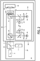
- a hair detector 26 according to a second example is shown in Fig. 2 .
- the hair detector 26 is based on a source 27 comprising two light sources 1, 2 of different wavelengths and linear polarization states following on a hair.
- the source 27 is adapted for emitting optical radiation comprising an incident polarization state.
- the source 27 comprises a first linearly polarized optical radiation source 1 and a second linearly polarized optical radiation source 2, wherein a combiner 32, in the second example a dichroic beam combiner 3, combines a first beam emitted from the first linearly polarized optical radiation source 1 and a second beam emitted from the second linearly polarized optical radiation source.
- the hair detector 26 further comprises an imaging unit 28 adapted for imaging a hair on a skin surface of a human or animal body part, wherein the imaging unit 28 comprises a detection unit 29 adapted for detecting optical radiation scattered and/or reflected by the hair and a control unit adapted for processing a signal from the detection unit 29 in order to recognize the hair.
- the control unit is not shown in Fig. 2 .
- the detection unit comprises four avalanche photo detectors 16, 18, 21, 23, wherein the optical path between each photo detector and a ratio increaser unit 30 comprises at least a focusing element 15, 17, 20, 22 or a combiner 14, 19, wherein the combiner 14, 19 corresponds to a dichroic beam splitter according to the second example.
- the imaging unit 28 further comprises a polarization transformer 9.
- the polarization transformer 9 corresponds to a quarter-wave plate, adapted for transforming the incident polarization state comprised by the optical radiation emitted from the source 27 to another polarization state comprised by an output beam directed to the skin surface.
- the detection unit 29 is positioned or arranged in an optical path of the optical radiation between the source 27 and the skin surface and/or the hair and is adapted for detecting scattered and/or reflected optical radiation comprising a first polarization state corresponding to the incident polarization state and a second polarization state being orthogonal to the first polarization state.
- the imaging unit 28 further comprises a lens comprised by the focusing unit 10, wherein the lens is adapted for focusing the output beam directed to the skin surface.
- a pinhole 33 is arranged in the optical path between the polarization transformer 9 and the focusing unit 10.
- the ratio increaser unit 30 arranged in an optical path of the optical radiation between the skin surface and the detection unit 29 is adapted for increasing the ratio of the optical radiation that returns from the hair to the optical radiation that returns from the skin surface, wherein the ratio increaser unit 30 comprises a beam splitter 24 being nearly or completely insensitive to a polarization change and a polarization beam splitter 5 being polarization-sensitive.
- Linearly polarized light emitted from the two light sources 1, 2 is combined by the combiner 32 and is transmitted through the beam splitter 24 and the polarization beam splitter 5, PBS for short.
- the resulting polarization state comprises a circular polarization state.
- the circularly polarized light comprised by the resulting light beam can be represented as a sum of two orthogonal linearly polarized components shifted in phase by plus or minus 90 degrees.
- This light beam is then focused by the focusing element 10 at the skin surface comprising a hair. Light is partially reflected at the interface between the skin and the immersion medium, such as air, water or any other medium, and at the interface between a hair and a medium and also scattered by the hair and the skin.
- the birefringence of the hair cortex induces a polarization change which is chosen as a function of hair diameter and wavelength.
- Light reflection from the medium-skin interface comprises a reflection from a dielectric surface comprising a refractive index larger than the refractive index of the light propagation medium, such as air for which it holds that n ⁇ 1. This introduces a phase shift of 180 degrees of one of the components of the incident circularly polarized light.
- the resulting polarization state comprises a linear polarization state comprising the same or a different orientation than that of the incident polarization state of the incident light, depending on the polarization change.
- each wavelength ⁇ 1 , ⁇ 2 of this light is separately detected by, respectively, the photo detectors 16 and 18.
- the light or radiation comprising the parallel polarization state is transmitted to the beam splitter 24, and each wavelength ⁇ 1 , ⁇ 2 of this light is separately detected by, respectively, the photo detectors 21 and 23.
- each wavelength ⁇ 1 , ⁇ 2 is detected separately.
- the control unit performs a mathematical subtraction and/or a division on a first signal, measured at the first wavelength ⁇ 1 and obtained by subtracting a signal corresponding to the detected optical radiation comprising the polarization state identical to the incident polarization state from a signal corresponding to the detected optical radiation comprising the polarization state orthogonal to the incident polarization state, relative to a second signal, measured at the second wavelength ⁇ 2 and obtained by subtracting a signal corresponding to the detected optical radiation comprising the polarization state identical to the incident polarization state from a signal corresponding to the detected optical radiation comprising the polarization state orthogonal to the incident polarization state.
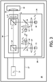
- the source 27 corresponds to a broadband source 31, which is shown in Fig. 3 .
- the broadband source corresponds to a super luminescent laser diode emitting in the ultraviolet-near infrared spectral range, UV-NIR for short, comprising a bandwidth of at least 50 nm and a central wavelength of 830 nm.
- Differential polarization imaging is applied in a similar way, by means of an imaging unit 28 and a control unit as described with respect to the second example shown in Fig. 2 , for light detected comprising two polarization states, i.e.
- a polarization state being equal to the incident polarization state or being shifted by 180 degrees and a polarization state being perpendicular to the incident polarization state used for at least two wavelength ranges, such as from a first wavelength to the center wavelength and from the center wavelength to a second wavelength.
- a broadband source 31 is applied instead of two light sources, such as the light source according to the second preferred embodiment of the invention. Since the polarization change for two specific wavelengths is chosen as a function of hair diameter, which in turn varies between 50 ⁇ m and 300 ⁇ m, the use of a super luminescent laser diode, SLD for short, makes the performance of the system independent of the hair diameter.
- the detection unit 29 detects scattered and/or reflected optical radiation in such predetermined wavelength ranges.
- the spectral bandwidth of the SLD is tuned by changing the drive current and temperature. This makes it possible to optimize the performance of the system, depending on the requirements needed.
- a laser diode shows multimode operation and, therefore, a number of axial modes are excited within the Gaussian gain profile, resulting in an effective larger spectral bandwidth.
- a light or optical power spectrum as a function of drive current representing the spectral bandwidth variation and the optical power vs. injection current characteristics of the SLD is shown in Fig. 4 , according to the third example.
- the inset shows the electroluminescence intensity spectra, EL intensity spectra for short, of the SLD for different currents. As expected, the light power increases with increasing current, however only to a saturation value. From a perspective of system implementation, this reduces the costs and size of the device.
- Fig. 5 shows a preferred embodiment of the invention, diagrammatically illustrating a shaving device 25.
- the shaving device 25 is adapted for detecting and for cutting a hair.
- the shaving device 25 comprises the hair detector 26 according to the second example, and is adapted for detecting the hair.
- the shaving device 25 further comprises a cutting laser comprised by an optical cutting source 6 arranged to supply an amount of optical energy to at least a portion of at least one hair and adapted for cutting the hair.
- the shaving device 25 comprises a glass plate 11 adapted for providing a plain surface, and a refractive index matching medium 12 adapted for providing a refractive index corresponding to a refractive index of a skin surface 13 of a human or animal body part.
- Fig. 5 also shows a reflecting mirror 4 for the detection wavelengths comprised by the dichroic beam combiner 3, a further reflecting mirror 7 at an end of the hair detector 26, wherein the reflecting mirror 7 is adapted for separating the radiation emitted from the hair detector 26 and the optical cutting source 6, and a scanning mirror 8.
- An application of the present disclosure is imaging hairs as birefringent objects in a non-birefringent background formed by the near skin.
- a high contrast is obtainable. Therefore, it becomes possible to detect hair with micron resolution and increased hair-skin contrast. Furthermore, it becomes possible to cut the hair with methods, such as LIOB methods or thermal methods.
- the increased specificity of the measurements i.e. reducing false-positives, makes discrimination between a hair and a skin structure distinct. This improves the detection efficiency and thus significantly improves the shaving quality.
Landscapes
- Physics & Mathematics (AREA)
- Health & Medical Sciences (AREA)
- Life Sciences & Earth Sciences (AREA)
- Chemical & Material Sciences (AREA)
- Analytical Chemistry (AREA)
- Biochemistry (AREA)
- General Health & Medical Sciences (AREA)
- General Physics & Mathematics (AREA)
- Immunology (AREA)
- Pathology (AREA)
- Investigating Or Analysing Materials By Optical Means (AREA)
- Dry Shavers And Clippers (AREA)
- Eye Examination Apparatus (AREA)
Claims (11)
- Rasiervorrichtung (25), die zum Detektieren und Schneiden eines Haares in der Nähe einer Hautoberfläche eines menschlichen Körperteils oder eines tierischen Körperteils angepasst ist, umfassend einen Detektor (26), der zum Detektieren des Haares angepasst ist, wobei die Rasiervorrichtung (25) weiter eine optische Schneidquelle (6), vorzugsweise einen Schneidlaser, umfasst, die so angeordnet ist, dass sie eine Menge an optischer Energie an mindestens einen Abschnitt mindestens eines Haares liefert und zum Schneiden des Haares angepasst ist, und wobei der Detektor (26) umfasst:- eine Quelle (27), die zum Emittieren optischer Strahlung angepasst ist, die mindestens eine erste Wellenlänge, eine zweite Wellenlänge und einen Einfalls-Polarisationszustand umfasst, und- eine Bildgebungseinheit (28), die zur Bildgebung des Haares in der Nähe der Hautoberfläche angepasst ist, wobei die Bildgebungseinheit (28) umfasst:- eine Detektionseinheit (29), die angeordnet ist zum separaten Detektieren, und separat bei der ersten Wellenlänge und der zweiten Wellenlänge, von optischer Strahlung, die vom Haar und/oder der Hautoberfläche gestreut und/oder reflektiert wird, umfassend einen ersten Polarisationszustand entsprechend dem Einfalls-Polarisationszustand, und optischer Strahlung, die vom Haar und/oder der Hautoberfläche gestreut und/oder reflektiert wird, umfassend einen zweiten Polarisationszustand, der sich vom ersten Polarisationszustand unterscheidet, und- eine Steuereinheit, die zum Verarbeiten eines Signals von der Detektionseinheit (29) zur Unterscheidung zwischen dem Haar und der Hautoberfläche angepasst ist, wobei die Steuereinheit weiter zum Steuern der optischen Schneidquelle (6) angepasst ist,wobei die Steuereinheit zum Durchführen einer mathematischen Subtraktion und/oder einer Division eines ersten Signals angepasst ist, das bei der ersten Wellenlänge gemessen und durch Subtrahieren eines Signals erhalten wird, das der erfassten optischen Strahlung entspricht, die den ersten Polarisationszustand umfasst, von einem Signal, das der erfassten optischen Strahlung entspricht, die den zweiten Polarisationszustand umfasst, relativ zu einem zweiten Signal, das bei der zweiten Wellenlänge gemessen und durch Subtrahieren eines Signals erhalten wird, das der erfassten optischen Strahlung entspricht, die den ersten Polarisationszustand umfasst, von einem Signal, das der erfassten optischen Strahlung entspricht, die den zweiten Polarisationszustand umfasst, zur Unterscheidung zwischen dem Haar und der Hautoberfläche.
- Rasiervorrichtung (25) nach Anspruch 1, wobei die Bildgebungseinheit (28) weiter einen Polarisationstransformator (9) umfasst, der angepasst ist zum Transformieren des Einfalls-Polarisationszustandes, der durch die von der Quelle (27) emittierte optische Strahlung umfasst wird, in einen anderen Polarisationszustand, der durch einen auf die Hautoberfläche gerichteten Ausgangsstrahl umfasst wird.
- Rasiervorrichtung (25) nach einem der vorstehenden Ansprüche, wobei die Bildgebungseinheit (28) weiter eine Vielzahl von Linsen und/oder eine Fokussiereinheit (10) umfasst, die zum Fokussieren des auf die Hautoberfläche gerichteten Ausgangsstrahls angepasst ist.
- Rasiervorrichtung (25) nach Anspruch 3, wobei die Fokussiereinheit (10) eine Linse, ein mikroskopisches Objektiv und/oder eine optische Klinge umfasst.
- Rasiervorrichtung (25) nach einem der Ansprüche 2 bis 4, wobei der Einfalls-Polarisationszustand einen linearen Polarisationszustand, einen zirkulären Polarisationszustand und/oder einen elliptischen Polarisationszustand umfasst, und das Transformieren in einen anderen Polarisationszustand einen Polarisationszustand umfasst, der einem Polarisationszustand entspricht, der sich von dem Einfalls-Polarisationszustand unterscheidet.
- Rasiervorrichtung (25) nach einem der vorstehenden Ansprüche, wobei die Bildgebungseinheit (28) weiter eine Verhältnis-Erhöhungseinheit (30) umfasst, die in einem optischen Pfad der optischen Strahlung zwischen der Hautoberfläche und der Detektionseinheit (29) angeordnet ist, wobei die Verhältnis-Erhöhungseinheit (30) angepasst ist, um ein Verhältnis der optischen Strahlung, die vom Haar zurückkehrt, zu der optischen Strahlung zu erhöhen, die von der Hautoberfläche zurückkehrt.
- Rasiervorrichtung (25) nach Anspruch 6, wobei die Verhältnis-Erhöhungseinheit (30) mindestens einen von einem Strahlteiler (24) und einem Polarisationsstrahlteiler (5), vorzugsweise einen Strahlteiler (24) und einen Polarisationsstrahlteiler (5), und/oder einen Faraday-Isolator umfasst.
- Rasiervorrichtung (25) nach einem der vorstehenden Ansprüche, wobei die Quelle (27) eine Breitbandquelle (31), vorzugsweise eine superlumineszierende Laserdiode mit einer Bandbreite von mindestens 30 nm, vorzugsweise einer Bandbreite von mindestens 50 nm, am besonders bevorzugt einer Bandbreite von mindestens 80 nm umfasst.
- Rasiervorrichtung (25) nach einem der Ansprüche 2 bis 8, wobei ein vorbestimmter Wellenlängenbereich zwischen der ersten und zweiten Wellenlänge in Abhängigkeit von mindestens einem der folgenden Parameter gewählt wird: Durchmesser des Haares, Doppelbrechung des Haares und Mittelwellenlänge der Quelle (27).
- Rasiervorrichtung (25) nach einem der vorstehenden Ansprüche, wobei die Quelle (27) eine erste linear polarisierte optische Strahlungsquelle (1) und eine zweite linear polarisierte optische Strahlungsquelle (2) umfasst, wobei ein Kombinierer (32), vorzugsweise ein dichroitischer Strahlkombinierer (3), einen ersten von der ersten linear polarisierten optischen Strahlungsquelle (1) emittierten Strahl und einen zweiten von der zweiten linear polarisierten optischen Strahlungsquelle (2) emittierten Strahl kombiniert.
- Rasiervorrichtung (25) nach einem der vorstehenden Ansprüche, wobei die Detektionseinheit (29) mindestens zwei Photodetektoren, vorzugsweise mindestens vier Photodetektoren (16, 18, 21, 23) umfasst, wobei bevorzugter jeder Photodetektor einem Lawinen-Photodetektor entspricht, wobei der optische Pfad zwischen jedem Photodetektor und der Verhältnis-Erhöhungseinheit (30) mindestens ein Fokussierelement (15, 17, 20, 22) oder einen Kombinierer (14, 19) umfasst, wobei der Kombinierer (14, 19) vorzugsweise einem dichroitischen Strahlteiler entspricht.
Priority Applications (1)
| Application Number | Priority Date | Filing Date | Title |
|---|---|---|---|
| EP10710907.6A EP2409134B1 (de) | 2009-03-19 | 2010-03-15 | Detektor für doppelbrechende objekte |
Applications Claiming Priority (3)
| Application Number | Priority Date | Filing Date | Title |
|---|---|---|---|
| EP09155609 | 2009-03-19 | ||
| EP10710907.6A EP2409134B1 (de) | 2009-03-19 | 2010-03-15 | Detektor für doppelbrechende objekte |
| PCT/IB2010/051100 WO2010106480A1 (en) | 2009-03-19 | 2010-03-15 | Detector for birefringent objects |
Publications (2)
| Publication Number | Publication Date |
|---|---|
| EP2409134A1 EP2409134A1 (de) | 2012-01-25 |
| EP2409134B1 true EP2409134B1 (de) | 2019-05-08 |
Family
ID=42235651
Family Applications (1)
| Application Number | Title | Priority Date | Filing Date |
|---|---|---|---|
| EP10710907.6A Active EP2409134B1 (de) | 2009-03-19 | 2010-03-15 | Detektor für doppelbrechende objekte |
Country Status (7)
| Country | Link |
|---|---|
| US (1) | US8699026B2 (de) |
| EP (1) | EP2409134B1 (de) |
| JP (1) | JP5738835B2 (de) |
| CN (1) | CN102356310B (de) |
| BR (1) | BRPI1006401B1 (de) |
| RU (1) | RU2521735C2 (de) |
| WO (1) | WO2010106480A1 (de) |
Families Citing this family (20)
| Publication number | Priority date | Publication date | Assignee | Title |
|---|---|---|---|---|
| US20100186234A1 (en) | 2009-01-28 | 2010-07-29 | Yehuda Binder | Electric shaver with imaging capability |
| WO2012164441A1 (en) | 2011-05-30 | 2012-12-06 | Koninklijke Philips Electronics N.V. | Hair treatment device having a light-based hair detector |
| JP5961265B2 (ja) * | 2011-08-22 | 2016-08-02 | コーニンクレッカ フィリップス エヌ ヴェKoninklijke Philips N.V. | 毛検出器を備えたヘアトリートメント装置 |
| WO2013068932A1 (en) | 2011-11-10 | 2013-05-16 | Koninklijke Philips Electronics N.V. | Hair detector with multiple focal points |
| IN2014CN04967A (de) | 2011-12-22 | 2015-09-18 | Koninkl Philips Nv | |
| CN104254274B (zh) * | 2012-04-24 | 2016-10-19 | 皇家飞利浦有限公司 | 具有基于光的毛发检测器的毛发处理设备 |
| US9457431B2 (en) * | 2012-05-22 | 2016-10-04 | Koninklijke Philips N.V. | Cutting head for a device for cutting hair |
| US10441357B2 (en) | 2012-05-22 | 2019-10-15 | Koninklijke Philips N.V. | Device for cutting hair |
| EP2854684B1 (de) * | 2012-06-04 | 2017-01-11 | Koninklijke Philips N.V. | Auf liob basierende haarschneidevorrichtung |
| CN104379079B (zh) * | 2012-07-31 | 2018-02-16 | 皇家飞利浦有限公司 | 激光的毛发切割器 |
| EP3498211B1 (de) | 2013-08-09 | 2024-12-25 | The General Hospital Corporation | Vorrichtung zur melasma-behandlung |
| US20170156796A1 (en) * | 2014-07-25 | 2017-06-08 | Koninklijke Philips N.V. | A device for cutting hair |
| WO2018007547A1 (en) * | 2016-07-07 | 2018-01-11 | Koninklijke Philips N.V. | Generating a guidance indicator and indicator signal |
| US20180149584A1 (en) * | 2016-11-29 | 2018-05-31 | Carol Y. Scarlett | Circular birefringence identification of materials |
| FR3067111B1 (fr) * | 2017-05-31 | 2019-08-30 | Saint-Gobain Glass France | Dispositifs optiques pour l'analyse qualite d'un vitrage. |
| CN107367487A (zh) * | 2017-06-12 | 2017-11-21 | 中国科学院苏州生物医学工程技术研究所 | 一种手持便携式皮肤疾病辅助检测装置 |
| MX2020001315A (es) * | 2017-08-01 | 2020-03-20 | Zoetis Services Llc | Aparato para analizar un medio, y aparato y metodo asociados para la identificacion de huevos. |
| US11003048B1 (en) * | 2019-12-13 | 2021-05-11 | VG Technology Inc. | Polarized imaging apparatus for use with a mobile device |
| EP3838339A1 (de) * | 2019-12-20 | 2021-06-23 | Koninklijke Philips N.V. | Behandlungsvorrichtungen und -verfahren |
| JP7641534B2 (ja) * | 2021-02-16 | 2025-03-07 | パナソニックIpマネジメント株式会社 | 電気かみそり |
Citations (1)
| Publication number | Priority date | Publication date | Assignee | Title |
|---|---|---|---|---|
| WO2004081549A1 (en) * | 2003-03-11 | 2004-09-23 | Koninklijke Philips Electronics N.V. | Spectroscopic analysis apparatus and method with excitation system and focus monitoring system |
Family Cites Families (14)
| Publication number | Priority date | Publication date | Assignee | Title |
|---|---|---|---|---|
| US3900252A (en) | 1973-10-31 | 1975-08-19 | Redken Laboratories Inc | Method and apparatus for analyzing hair structure |
| IL97531A (en) * | 1991-03-12 | 1995-12-31 | Kelman Elliot | Hair cutting apparatus |
| JPH05142156A (ja) * | 1991-11-20 | 1993-06-08 | Matsushita Electric Ind Co Ltd | 異物検査装置 |
| IL109882A0 (en) * | 1994-06-02 | 1994-10-07 | Kelman Elliot | Hair cutting apparatus |
| RU2083354C1 (ru) * | 1996-07-16 | 1997-07-10 | Владимир Викторович Касьяненко | Способ ухода за волосами и кожей и устройство для его осуществления |
| RU2181572C2 (ru) * | 2000-06-30 | 2002-04-27 | Горбатова Наталья Евгеньевна | Лазерный медицинский прибор |
| DE10137340A1 (de) | 2001-07-31 | 2003-02-20 | Heidelberger Druckmasch Ag | Verfahren und Vorrichtung zur Erkennung von Fremdkörpern und Oberflächendefekten auf einer transparenten Vorlage sowie zur Korrektur von dadurch verursachten Bildfehlern einer Abbildung der Vorlage |
| BRPI0417255B1 (pt) * | 2003-12-03 | 2018-02-14 | Fpinnovations | Aparelho para determinar retardos de fase relativos e orientações dos eixos ópticos de diferentes camadas em um espécime de fibra celulósica birrefringente de diversas camadas, e, método para determinar o retardo de fase relativo relacionado à espessura de parede e ângulo de fibrila de uma fibra de madeira intacta |
| WO2005102153A1 (en) | 2004-04-20 | 2005-11-03 | Koninklijke Philips Electronics N.V. | A hair-detection device |
| US20060241495A1 (en) * | 2005-03-23 | 2006-10-26 | Eastman Kodak Company | Wound healing monitoring and treatment |
| US7460248B2 (en) * | 2006-05-15 | 2008-12-02 | Carestream Health, Inc. | Tissue imaging system |
| CN101557770B (zh) | 2006-12-12 | 2011-04-13 | 皇家飞利浦电子股份有限公司 | 减少毛发生长的设备 |
| EP2143180A2 (de) | 2007-03-29 | 2010-01-13 | Koninklijke Philips Electronics N.V. | Verfahren und vorrichtung zur erzeugung eines laserstrahls, laserbehandlungsvorrichtung und lasererkennungsvorrichtung |
| US8223322B2 (en) * | 2009-09-25 | 2012-07-17 | Bossa Nova Technologies, Llc | Visual appearance measurement method and system for randomly and regularly arranged birefringent fibers |
-
2010
- 2010-03-15 EP EP10710907.6A patent/EP2409134B1/de active Active
- 2010-03-15 BR BRPI1006401-0A patent/BRPI1006401B1/pt not_active IP Right Cessation
- 2010-03-15 JP JP2012500349A patent/JP5738835B2/ja not_active Expired - Fee Related
- 2010-03-15 WO PCT/IB2010/051100 patent/WO2010106480A1/en not_active Ceased
- 2010-03-15 CN CN201080012467.8A patent/CN102356310B/zh not_active Expired - Fee Related
- 2010-03-15 US US13/256,513 patent/US8699026B2/en not_active Expired - Fee Related
- 2010-03-15 RU RU2011142161/28A patent/RU2521735C2/ru not_active IP Right Cessation
Patent Citations (1)
| Publication number | Priority date | Publication date | Assignee | Title |
|---|---|---|---|---|
| WO2004081549A1 (en) * | 2003-03-11 | 2004-09-23 | Koninklijke Philips Electronics N.V. | Spectroscopic analysis apparatus and method with excitation system and focus monitoring system |
Also Published As
| Publication number | Publication date |
|---|---|
| EP2409134A1 (de) | 2012-01-25 |
| WO2010106480A1 (en) | 2010-09-23 |
| BRPI1006401A8 (pt) | 2017-09-19 |
| US20120002204A1 (en) | 2012-01-05 |
| CN102356310A (zh) | 2012-02-15 |
| CN102356310B (zh) | 2015-04-22 |
| BRPI1006401A2 (pt) | 2016-06-07 |
| JP2012520721A (ja) | 2012-09-10 |
| RU2011142161A (ru) | 2013-04-27 |
| RU2521735C2 (ru) | 2014-07-10 |
| BRPI1006401B1 (pt) | 2019-10-01 |
| US8699026B2 (en) | 2014-04-15 |
| JP5738835B2 (ja) | 2015-06-24 |
Similar Documents
| Publication | Publication Date | Title |
|---|---|---|
| EP2409134B1 (de) | Detektor für doppelbrechende objekte | |
| EP2091457B1 (de) | Vorrichtung und verfahren zur bilddarstellung von hautobjekten und verfahren und vorrichtung zur reduzierung des haarwuchses damit | |
| US6734974B2 (en) | Terahertz imaging with dynamic aperture | |
| RU2631195C2 (ru) | Устройство для ухода за волосами с датчиком волос на основе света | |
| JP2009300108A (ja) | テラヘルツ分光装置 | |
| US9295520B2 (en) | Hair detector with multiple focal points | |
| CN103826529B (zh) | 具有毛发检测器的毛发处理设备 | |
| JP2000352558A (ja) | テラヘルツ波分光器 | |
| US20120062879A1 (en) | Measuring Instrument for Determining the Tissue Alcohol Concentration | |
| Parnet et al. | Orthogonality breaking through few-mode optical fiber | |
| JP6541366B2 (ja) | テラヘルツ波計測装置 | |
| US7608827B2 (en) | Near-field terahertz imaging | |
| Benelajla et al. | Modal imaging of a laser Gaussian-beam reflected off a surface | |
| Wu et al. | The spectral characteristics of the splitting angle for double Wollaston prism | |
| Sun et al. | Confocal photothermal microscopy of thin films based on etalon and thermal lensing effects | |
| Afshinmanesh et al. | An integrated plasmonic polarimeter | |
| JP2019144276A (ja) | テラヘルツ波計測装置 |
Legal Events
| Date | Code | Title | Description |
|---|---|---|---|
| PUAI | Public reference made under article 153(3) epc to a published international application that has entered the european phase |
Free format text: ORIGINAL CODE: 0009012 |
|
| 17P | Request for examination filed |
Effective date: 20111019 |
|
| AK | Designated contracting states |
Kind code of ref document: A1 Designated state(s): AT BE BG CH CY CZ DE DK EE ES FI FR GB GR HR HU IE IS IT LI LT LU LV MC MK MT NL NO PL PT RO SE SI SK SM TR |
|
| DAX | Request for extension of the european patent (deleted) | ||
| RAP1 | Party data changed (applicant data changed or rights of an application transferred) |
Owner name: KONINKLIJKE PHILIPS N.V. |
|
| STAA | Information on the status of an ep patent application or granted ep patent |
Free format text: STATUS: EXAMINATION IS IN PROGRESS |
|
| 17Q | First examination report despatched |
Effective date: 20170413 |
|
| GRAP | Despatch of communication of intention to grant a patent |
Free format text: ORIGINAL CODE: EPIDOSNIGR1 |
|
| STAA | Information on the status of an ep patent application or granted ep patent |
Free format text: STATUS: GRANT OF PATENT IS INTENDED |
|
| INTG | Intention to grant announced |
Effective date: 20181017 |
|
| GRAS | Grant fee paid |
Free format text: ORIGINAL CODE: EPIDOSNIGR3 |
|
| GRAA | (expected) grant |
Free format text: ORIGINAL CODE: 0009210 |
|
| STAA | Information on the status of an ep patent application or granted ep patent |
Free format text: STATUS: THE PATENT HAS BEEN GRANTED |
|
| AK | Designated contracting states |
Kind code of ref document: B1 Designated state(s): AT BE BG CH CY CZ DE DK EE ES FI FR GB GR HR HU IE IS IT LI LT LU LV MC MK MT NL NO PL PT RO SE SI SK SM TR |
|
| REG | Reference to a national code |
Ref country code: GB Ref legal event code: FG4D |
|
| REG | Reference to a national code |
Ref country code: CH Ref legal event code: EP Ref country code: AT Ref legal event code: REF Ref document number: 1130933 Country of ref document: AT Kind code of ref document: T Effective date: 20190515 |
|
| REG | Reference to a national code |
Ref country code: DE Ref legal event code: R096 Ref document number: 602010058725 Country of ref document: DE Ref country code: IE Ref legal event code: FG4D |
|
| REG | Reference to a national code |
Ref country code: NL Ref legal event code: MP Effective date: 20190508 |
|
| REG | Reference to a national code |
Ref country code: LT Ref legal event code: MG4D |
|
| PG25 | Lapsed in a contracting state [announced via postgrant information from national office to epo] |
Ref country code: FI Free format text: LAPSE BECAUSE OF FAILURE TO SUBMIT A TRANSLATION OF THE DESCRIPTION OR TO PAY THE FEE WITHIN THE PRESCRIBED TIME-LIMIT Effective date: 20190508 Ref country code: LT Free format text: LAPSE BECAUSE OF FAILURE TO SUBMIT A TRANSLATION OF THE DESCRIPTION OR TO PAY THE FEE WITHIN THE PRESCRIBED TIME-LIMIT Effective date: 20190508 Ref country code: PT Free format text: LAPSE BECAUSE OF FAILURE TO SUBMIT A TRANSLATION OF THE DESCRIPTION OR TO PAY THE FEE WITHIN THE PRESCRIBED TIME-LIMIT Effective date: 20190908 Ref country code: SE Free format text: LAPSE BECAUSE OF FAILURE TO SUBMIT A TRANSLATION OF THE DESCRIPTION OR TO PAY THE FEE WITHIN THE PRESCRIBED TIME-LIMIT Effective date: 20190508 Ref country code: NL Free format text: LAPSE BECAUSE OF FAILURE TO SUBMIT A TRANSLATION OF THE DESCRIPTION OR TO PAY THE FEE WITHIN THE PRESCRIBED TIME-LIMIT Effective date: 20190508 Ref country code: ES Free format text: LAPSE BECAUSE OF FAILURE TO SUBMIT A TRANSLATION OF THE DESCRIPTION OR TO PAY THE FEE WITHIN THE PRESCRIBED TIME-LIMIT Effective date: 20190508 Ref country code: HR Free format text: LAPSE BECAUSE OF FAILURE TO SUBMIT A TRANSLATION OF THE DESCRIPTION OR TO PAY THE FEE WITHIN THE PRESCRIBED TIME-LIMIT Effective date: 20190508 Ref country code: NO Free format text: LAPSE BECAUSE OF FAILURE TO SUBMIT A TRANSLATION OF THE DESCRIPTION OR TO PAY THE FEE WITHIN THE PRESCRIBED TIME-LIMIT Effective date: 20190808 |
|
| PG25 | Lapsed in a contracting state [announced via postgrant information from national office to epo] |
Ref country code: GR Free format text: LAPSE BECAUSE OF FAILURE TO SUBMIT A TRANSLATION OF THE DESCRIPTION OR TO PAY THE FEE WITHIN THE PRESCRIBED TIME-LIMIT Effective date: 20190809 Ref country code: LV Free format text: LAPSE BECAUSE OF FAILURE TO SUBMIT A TRANSLATION OF THE DESCRIPTION OR TO PAY THE FEE WITHIN THE PRESCRIBED TIME-LIMIT Effective date: 20190508 Ref country code: BG Free format text: LAPSE BECAUSE OF FAILURE TO SUBMIT A TRANSLATION OF THE DESCRIPTION OR TO PAY THE FEE WITHIN THE PRESCRIBED TIME-LIMIT Effective date: 20190808 |
|
| REG | Reference to a national code |
Ref country code: AT Ref legal event code: MK05 Ref document number: 1130933 Country of ref document: AT Kind code of ref document: T Effective date: 20190508 |
|
| PG25 | Lapsed in a contracting state [announced via postgrant information from national office to epo] |
Ref country code: RO Free format text: LAPSE BECAUSE OF FAILURE TO SUBMIT A TRANSLATION OF THE DESCRIPTION OR TO PAY THE FEE WITHIN THE PRESCRIBED TIME-LIMIT Effective date: 20190508 Ref country code: SK Free format text: LAPSE BECAUSE OF FAILURE TO SUBMIT A TRANSLATION OF THE DESCRIPTION OR TO PAY THE FEE WITHIN THE PRESCRIBED TIME-LIMIT Effective date: 20190508 Ref country code: CZ Free format text: LAPSE BECAUSE OF FAILURE TO SUBMIT A TRANSLATION OF THE DESCRIPTION OR TO PAY THE FEE WITHIN THE PRESCRIBED TIME-LIMIT Effective date: 20190508 Ref country code: DK Free format text: LAPSE BECAUSE OF FAILURE TO SUBMIT A TRANSLATION OF THE DESCRIPTION OR TO PAY THE FEE WITHIN THE PRESCRIBED TIME-LIMIT Effective date: 20190508 Ref country code: EE Free format text: LAPSE BECAUSE OF FAILURE TO SUBMIT A TRANSLATION OF THE DESCRIPTION OR TO PAY THE FEE WITHIN THE PRESCRIBED TIME-LIMIT Effective date: 20190508 Ref country code: AT Free format text: LAPSE BECAUSE OF FAILURE TO SUBMIT A TRANSLATION OF THE DESCRIPTION OR TO PAY THE FEE WITHIN THE PRESCRIBED TIME-LIMIT Effective date: 20190508 |
|
| REG | Reference to a national code |
Ref country code: DE Ref legal event code: R097 Ref document number: 602010058725 Country of ref document: DE |
|
| PG25 | Lapsed in a contracting state [announced via postgrant information from national office to epo] |
Ref country code: IT Free format text: LAPSE BECAUSE OF FAILURE TO SUBMIT A TRANSLATION OF THE DESCRIPTION OR TO PAY THE FEE WITHIN THE PRESCRIBED TIME-LIMIT Effective date: 20190508 Ref country code: SM Free format text: LAPSE BECAUSE OF FAILURE TO SUBMIT A TRANSLATION OF THE DESCRIPTION OR TO PAY THE FEE WITHIN THE PRESCRIBED TIME-LIMIT Effective date: 20190508 |
|
| PLBE | No opposition filed within time limit |
Free format text: ORIGINAL CODE: 0009261 |
|
| STAA | Information on the status of an ep patent application or granted ep patent |
Free format text: STATUS: NO OPPOSITION FILED WITHIN TIME LIMIT |
|
| RAP2 | Party data changed (patent owner data changed or rights of a patent transferred) |
Owner name: KONINKLIJKE PHILIPS N.V. |
|
| PG25 | Lapsed in a contracting state [announced via postgrant information from national office to epo] |
Ref country code: TR Free format text: LAPSE BECAUSE OF FAILURE TO SUBMIT A TRANSLATION OF THE DESCRIPTION OR TO PAY THE FEE WITHIN THE PRESCRIBED TIME-LIMIT Effective date: 20190508 |
|
| 26N | No opposition filed |
Effective date: 20200211 |
|
| PG25 | Lapsed in a contracting state [announced via postgrant information from national office to epo] |
Ref country code: PL Free format text: LAPSE BECAUSE OF FAILURE TO SUBMIT A TRANSLATION OF THE DESCRIPTION OR TO PAY THE FEE WITHIN THE PRESCRIBED TIME-LIMIT Effective date: 20190508 |
|
| PGFP | Annual fee paid to national office [announced via postgrant information from national office to epo] |
Ref country code: GB Payment date: 20200327 Year of fee payment: 11 |
|
| PG25 | Lapsed in a contracting state [announced via postgrant information from national office to epo] |
Ref country code: SI Free format text: LAPSE BECAUSE OF FAILURE TO SUBMIT A TRANSLATION OF THE DESCRIPTION OR TO PAY THE FEE WITHIN THE PRESCRIBED TIME-LIMIT Effective date: 20190508 |
|
| PGFP | Annual fee paid to national office [announced via postgrant information from national office to epo] |
Ref country code: FR Payment date: 20200326 Year of fee payment: 11 |
|
| PGFP | Annual fee paid to national office [announced via postgrant information from national office to epo] |
Ref country code: DE Payment date: 20200330 Year of fee payment: 11 |
|
| PG25 | Lapsed in a contracting state [announced via postgrant information from national office to epo] |
Ref country code: MC Free format text: LAPSE BECAUSE OF FAILURE TO SUBMIT A TRANSLATION OF THE DESCRIPTION OR TO PAY THE FEE WITHIN THE PRESCRIBED TIME-LIMIT Effective date: 20190508 |
|
| REG | Reference to a national code |
Ref country code: CH Ref legal event code: PL |
|
| REG | Reference to a national code |
Ref country code: BE Ref legal event code: MM Effective date: 20200331 |
|
| PG25 | Lapsed in a contracting state [announced via postgrant information from national office to epo] |
Ref country code: LU Free format text: LAPSE BECAUSE OF NON-PAYMENT OF DUE FEES Effective date: 20200315 |
|
| PG25 | Lapsed in a contracting state [announced via postgrant information from national office to epo] |
Ref country code: LI Free format text: LAPSE BECAUSE OF NON-PAYMENT OF DUE FEES Effective date: 20200331 Ref country code: IE Free format text: LAPSE BECAUSE OF NON-PAYMENT OF DUE FEES Effective date: 20200315 Ref country code: CH Free format text: LAPSE BECAUSE OF NON-PAYMENT OF DUE FEES Effective date: 20200331 |
|
| PG25 | Lapsed in a contracting state [announced via postgrant information from national office to epo] |
Ref country code: BE Free format text: LAPSE BECAUSE OF NON-PAYMENT OF DUE FEES Effective date: 20200331 |
|
| REG | Reference to a national code |
Ref country code: DE Ref legal event code: R119 Ref document number: 602010058725 Country of ref document: DE |
|
| GBPC | Gb: european patent ceased through non-payment of renewal fee |
Effective date: 20210315 |
|
| PG25 | Lapsed in a contracting state [announced via postgrant information from national office to epo] |
Ref country code: FR Free format text: LAPSE BECAUSE OF NON-PAYMENT OF DUE FEES Effective date: 20210331 Ref country code: GB Free format text: LAPSE BECAUSE OF NON-PAYMENT OF DUE FEES Effective date: 20210315 Ref country code: DE Free format text: LAPSE BECAUSE OF NON-PAYMENT OF DUE FEES Effective date: 20211001 |
|
| PG25 | Lapsed in a contracting state [announced via postgrant information from national office to epo] |
Ref country code: MT Free format text: LAPSE BECAUSE OF FAILURE TO SUBMIT A TRANSLATION OF THE DESCRIPTION OR TO PAY THE FEE WITHIN THE PRESCRIBED TIME-LIMIT Effective date: 20190508 Ref country code: CY Free format text: LAPSE BECAUSE OF FAILURE TO SUBMIT A TRANSLATION OF THE DESCRIPTION OR TO PAY THE FEE WITHIN THE PRESCRIBED TIME-LIMIT Effective date: 20190508 |
|
| PG25 | Lapsed in a contracting state [announced via postgrant information from national office to epo] |
Ref country code: MK Free format text: LAPSE BECAUSE OF FAILURE TO SUBMIT A TRANSLATION OF THE DESCRIPTION OR TO PAY THE FEE WITHIN THE PRESCRIBED TIME-LIMIT Effective date: 20190508 Ref country code: IS Free format text: LAPSE BECAUSE OF FAILURE TO SUBMIT A TRANSLATION OF THE DESCRIPTION OR TO PAY THE FEE WITHIN THE PRESCRIBED TIME-LIMIT Effective date: 20190908 |