EP2408703B1 - Electromagnetic safety trigger - Google Patents
Electromagnetic safety trigger Download PDFInfo
- Publication number
- EP2408703B1 EP2408703B1 EP09841987.2A EP09841987A EP2408703B1 EP 2408703 B1 EP2408703 B1 EP 2408703B1 EP 09841987 A EP09841987 A EP 09841987A EP 2408703 B1 EP2408703 B1 EP 2408703B1
- Authority
- EP
- European Patent Office
- Prior art keywords
- speed
- car
- safety
- over
- link
- Prior art date
- Legal status (The legal status is an assumption and is not a legal conclusion. Google has not performed a legal analysis and makes no representation as to the accuracy of the status listed.)
- Not-in-force
Links
Images


Classifications
-
- B—PERFORMING OPERATIONS; TRANSPORTING
- B66—HOISTING; LIFTING; HAULING
- B66B—ELEVATORS; ESCALATORS OR MOVING WALKWAYS
- B66B5/00—Applications of checking, fault-correcting, or safety devices in elevators
- B66B5/02—Applications of checking, fault-correcting, or safety devices in elevators responsive to abnormal operating conditions
- B66B5/04—Applications of checking, fault-correcting, or safety devices in elevators responsive to abnormal operating conditions for detecting excessive speed
- B66B5/06—Applications of checking, fault-correcting, or safety devices in elevators responsive to abnormal operating conditions for detecting excessive speed electrical
Definitions
- the present invention relates generally to an electronic over-acceleration and over-speed protection system for an elevator.
- Elevators include a safety system to stop an elevator from traveling at excessive speeds in response to an elevator component breaking or otherwise becoming inoperative.
- elevator safety systems include a mechanical speed sensing device typically referred to as a governor and safeties or clamping mechanisms that are mounted to the elevator car frame for selectively gripping elevator guide rails. If the hoist ropes break or other elevator operational components fail, causing the elevator car to travel at an excessive speed, the governor triggers the safeties to slow or stop the car.
- the safeties include brake pads that are mounted for movement with the governor rope and brake housings that are mounted for movement with the elevator car.
- the brake housings are wedge shaped, such that as the brake pads are moved in a direction opposite from the brake housings, the brake pads are forced into frictional contact with the guide rails. Eventually the brake pads become wedged between the guide rails and the brake housing such that there is no relative movement between the elevator car and the guide rails.
- the brake housing i.e., the elevator car
- the brake housing must be moved upward while the governor rope is simultaneously released.
- An electromagnetic safety trigger for engaging a safety of an elevator system mass includes a link kinematically connected to the safety, a linear actuator connected to the mass, an electromagnet connected to the linear actuator, and a spring connected between the link and the mass.
- the electromagnet is operable to release the link to allow the spring to move the link to engage the safety.
- FIG. 1 shows prior art elevator system 10, which includes cables 12, car frame 14, car 16, roller guides 18, guide rails 20, governor 22, safeties 24, linkages 26, levers 28, and lift rods 30.
- Governor 22 includes governor sheave 32, rope loop 34, and tensioning sheave 36.
- Cables 12 are connected to car frame 14 and a counterweight (not shown in FIG. 1 ) inside a hoistway.
- Car 16, which is attached to car frame 14, moves up and down the hoistway by force transmitted through cables 12 to car frame 14 by an elevator drive (not shown) commonly located in the machine room at the top of the hoistway.
- Roller guides 18 are attached to car frame 14 and guide car frame 14 and car 16 up and down the hoistway along guide rails 20.
- Governor sheave 32 is mounted at an upper end of the hoistway.
- Rope loop 34 is wrapped partially around governor sheave 32 and partially around tensioning sheave 36 (located in this embodiment at a bottom end of the hoistway). Rope loop 34 is also connected to elevator car 16 at lever 28, ensuring that the angular velocity of governor sheave 32 is directly related to the speed of elevator car 16.
- governor 22 In elevator system 10 as shown in FIG. 1 , governor 22, an electromechanical brake (not shown) located in the machine room, and safeties 24 act to stop elevator car 16 if car 16 exceeds a set speed as it travels inside the hoistway. If car 16 reaches an over-speed condition, governor 22 is triggered initially to engage a switch, which in turn cuts power to the elevator drive and drops the brake to arrest movement of the drive sheave and thereby arrest movement of car 16. If, however, cables 12 break or car 16 otherwise experiences a free-fall condition unaffected by the brake, governor 22 may then act to trigger safeties 24 to arrest movement of car 16. In addition to engaging a switch to drop the brake, governor 22 also releases a clutching device that grips the governor rope 34.
- governor rope 34 is connected to safeties 24 through mechanical linkages 26, levers 28, and lift rods 30. As car 16 continues its descent unaffected by the brake, governor rope 34, which is now prevented from moving by actuated governor 22, pulls on operating lever 28. Operating lever 28 "sets" safeties 24 by moving linkages 26 connected to lift rods 30, which lift rods 30 cause safeties 24 to engage guide rails 20 to bring car 16 to a stop.
- Embodiments of the present invention therefore include an electronic system capable of triggering the machine room brake and releasing an electromagnetic safety trigger with low hysteresis and with minimal power requirements to engage the safeties when particular car over-speed and/or over-acceleration conditions are detected.
- the electromagnetic trigger may be reset automatically and may be released to engage the safeties during the reset procedure.
- An over-speed and over-acceleration detection and processing system is configured to decrease response time and to reduce the occurrence of false triggers caused by conditions unrelated to passenger safety, such as passengers jumping inside the elevator car.
- FIG. 2 is a schematic of elevator system 40 according to the present invention including car 16, speed detector 42, acceleration detector 44, electromagnetic safety trigger 46, and controller 48.
- Speed detector 42 is an electromechanical device configured to measure the speed of car 16 as it travels inside the hoistway during operation of elevator system 40 and to electronically communicate with controller 48.
- speed detector 42 may be a tachometer, which is also referred to as a generator.
- a tachometer is a device that measures the speed of a rotating component in, for example, revolutions per minute (RPM).
- RPM revolutions per minute
- the tachometer will either electronically measure the mechanical rotation or will translate a mechanical measurement into electronic signals for interpretation by controller 48.
- Acceleration detector 44 may be an electronic device that is configured to measure the acceleration of the car 16. Acceleration detector 44 may be, for example, an accelerometer.
- One type of accelerometer that may be used is a micro electro-mechanical system (MEMS) that commonly consists of a cantilever beam with a proof mass (also known as seismic mass). Under the influence of acceleration, the proof mass deflects from its neutral position. The deflection of the proof mass may be measured by analog or digital methods. For example, the variation in capacitance between a set of fixed beams and a set of beams attached to the proof mass may be measured.
- MEMS micro electro-mechanical system
- Controller 48 may be, for example, a circuit board including microprocessor 48A, input/output (I/O) interface 48B, indicators 48C (which may be, for example, light emitting diodes), and safety chain switch 48D. Controller 48 is powered by power source 50 with battery backup 52.
- I/O input/output
- indicators 48C which may be, for example, light emitting diodes
- safety chain switch 48D safety chain switch 48D. Controller 48 is powered by power source 50 with battery backup 52.
- speed detector 42, acceleration detector 44, electromagnetic safety trigger 46, and controller 48 are all connected to car 16.
- speed detector 42 is mounted to the top of car 16
- acceleration detector 44 may be mounted on a circuit board of controller 48.
- speed detector 42 and acceleration detector 44 may be mounted to car 16 in various locations that are appropriate for making speed/acceleration measurements.
- Controller 48 is configured to receive and interpret signals from the speed detector 42 and acceleration detector 44, and to control electromagnetic safety trigger 46.
- the tachometer may be mounted to an idler sheave on top of car 16.
- the idler sheave will rotate at a speed related to the speed of car 16.
- the tachometer may therefore be configured to measure the speed of the car indirectly by measuring the speed at which the idler sheave rotates.
- a static rope may be suspended in the hoistway adjacent to car 16 and the tachometer may be connected to the rope.
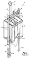
- FIG. 3A-3C show tachometer 54 including mounting bracket 56, electrical generator 58, drive sheave 60, and tensioning sheave 62.
- FIG. 3A is a plan view of tachometer 54.
- FIGS. 3B and 3C are elevation front and side views of tachometer 54 respectively.
- Tachometer 54 may be connected to car 16 by mounting bracket 56.
- Generator 58, drive sheave 60, and tensioning sheave 62 are all connected to mounting bracket 56.
- Drive sheave 60 is rotatably connected to generator 58.
- a static rope suspended in the hoistway may run up from the bottom of the hoistway and wrap partially over the top of tensioning sheave 62, under drive sheave 60 and up toward the top of the hoistway.
- a tachometer may be driven by engaging the stationary guide rails along which car 16 is guided up and down the hoistway.
- Controller 48 receives inputs from speed detector 42 and acceleration detector 44, and provides an output electromagnetic safety trigger 46. Controller 48 also includes safety chain switch 48D, which forms a part of safety chain 64 of elevator system 40. Safety chain 64 is a series of electro-mechanical devices distributed inside the hoistway and connected to the elevator drive and brake in the machine room.
- Electromagnetic safety trigger 46 is arranged on car 16 to be connected to the car safeties, which, for clarity, are not shown in FIG. 2 but which may be arranged and function similar to safeties 24 described with reference to FIG. 1.
- FIG. 1 shows safeties 24 arranged toward the bottom of car 16, and electromagnetic safety trigger 46 may also be mounted on the bottom of car 16.
- Alternative embodiments include elevator systems with safeties and electromagnetic safety trigger 46 arranged toward the top of the car.
- controller 48 receives signals from speed detector 42 and acceleration detector 44, and interprets the information to determine if an unsafe over-speed and/or over-acceleration condition has occurred. In the event car 16 experiences an unsafe over-speed and/or over-acceleration condition, controller 48 first opens safety chain switch 48D to safety chain 64 of elevator system 40. Opening switch 48D breaks safety chain 64 to interrupt power to the elevator drive 66 (typically located in the machine room at the upper end of the hoistway) and activate or drop brake 68 on the drive sheave of elevator drive 66.
- FIGS. 4A and 4B are schematic illustrations of electromagnetic safety trigger 46 according to the present invention employed in an elevator system including safeties 70A and 70B.
- Safety trigger 46 includes link 72, linear actuator 74, electromagnet 76, and spring 78.
- FIG. 4A shows trigger 46 in a ready state waiting to be released to engage safeties 70A, 70B.
- FIG. 4B shows trigger 46 released to engage safeties 70A, 70B.
- the components of trigger 46 and safeties 70A, 70B will, generally speaking, be mounted to the elevator system mass against which they are guarding unsafe conditions including, for example, a car or a counterweight.
- Safeties 70A, 70B may be similar in arrangement and configuration to safeties 24 shown in FIG. 1 , or may be any other safety device capable of being mechanically engaged by trigger 46 and of slowing or stopping an elevator system mass in an unsafe over-speed and/or over-acceleration condition.
- link 72 is kinematically connected to safeties 70A, 70B by pivot points 80A, 80B and safety lift rods 82A, 82B, respectively.
- link 72 may be connected to safeties 70A, 70B by simpler or more complex kinematic mechanisms in any arrangement that causes safeties 70A, 70B to be engaged when link 72 is moved.
- alternative embodiments may include a trigger 46 for each safety 70.
- Linear actuator 74 is connected to one side of elevator car 16.
- Electromagnet 76 is connected to linear actuator 74 and magnetically connected to link 72.
- Spring 78 is connected between link 72 and car 16.
- electromagnetic safety trigger 46 is operable to engage safeties 70, 70B in the event an unsafe over-speed or over-acceleration condition is detected for car 16.
- trigger 46 is configured to break the magnetic connection between electromagnet 76 and link 72 by actuating electromagnet 76 when an over-speed or over-acceleration condition occurs.
- link 72 is allowed to move away from electromagnetic 76, which releases the energy stored in compressed spring 78 to cause spring 78 to decompress. Decompressing spring 78, in turn, moves link 72 to raise lift rods 82A, 82B and thereby engage safeties 70A, 70B to slow or stop car 16.
- trigger 46 may be automatically reset.
- Linear actuator 74 is configured to extend to position electromagnet 76 to grab link 72, i.e. reestablish the magnetic connection, after link 72 has moved to engage safeties 70, 70B.
- Linear actuator 74 may then retract electromagnet 76, which is magnetically connected to link 72 to compress spring 78 and disengage safeties 70, 70B.
- trigger 46 may engage safeties 70, 70B during a reset operation by causing electromagnet 76 to release link 72 while linear actuator 74 is retracting.
- FIG. 5 is a broken plane view showing one implementation of electromagnetic safety trigger 86 according to the present invention mounted toward the bottom of elevator car 16 adjacent safety lift rod 90.
- Trigger 86 includes link 92, linear actuator 94, electromagnet 96, and coil spring 98.
- one end of link 92 is connected to lift rod 90.
- the opposite end of link 92 is connected to coil spring 98 and magnetically connected to electromagnet 96.
- link 92 is pivotally connected to car 88 at pivot point 100.
- Linear actuator 94 is connected to electromagnet 96.
- Coil spring 98 is connected to car 88.
- Trigger 86 is shown in a ready state with coil spring 98 fully compressed and electromagnet 96 magnetically connected to link 92.
- Electromagnet 96 is configured to be magnetized when in a de-energized state and demagnetized when in an energized state. Therefore, during normal safe operation of car 88, electromagnet 96 holds link 92 and compressed coil spring 98 without the need for a continuous supply of electricity.
- trigger 86 may be released to engage the safety connected to lift rod 90 by sending an electrical pulse to electromagnet 96 to defeat the magnetic connection to link 92, thereby releasing the energy stored in compressed spring 98 to cause spring 98 to decompress. Decompressing spring 98, in turn, moves link 92 to move lift rod 90 and thereby engage the safety to slow or stop car 88.
- Linear actuator 94 is an electrical actuator including electric motor 94a operably connected to drive shaft 94b.
- Motor 94a may employ, for example, a ball screw or worm screw drive system to translate the rotational motion of motor 94a into linear motion of shaft 94b.
- motor 94a may be non-backdrivable to make trigger 86 more energy efficient and less complex.
- Non-backdrivable actuators may be set to a particular position, e.g. the extension or retraction position of shaft 94b, and held there without supplying the actuator with a continuous supply of electricity.
- Drive shaft 94b will only move during a reset operation, first to connect to electromagnet 96, and then to move the safety mechanism back to its reset location.
- trigger 86 shown in FIG. 5 employs coil spring 98
- alternative embodiments may include different mechanical springs or other resilient members.
- trigger 86 could employ a torsion spring connected to link 92 at pivot point 100. The torsion spring could be set to be held in compression when actuator 94 is retracted and electromagnet 96 is magnetically connected to link 92.
- elevator systems are designed to detect and engage the elevator safeties under runaway and free fall conditions.
- a runaway condition is when the elevator machine room brakes fail to hold the car as it travels in either direction generating a threshold maximum acceleration.
- a free fall condition is an elevator traveling down at 1g. Activation of the safeties commonly means that disengaging the drive system and dropping the machine room brake has failed or is expected to fail to stop the elevator car from traveling at unsafe speeds and/or accelerations.
- Elevator codes specify the maximum speed at which the safeties are required to apply a stopping force to the elevator. Some jurisdictions also specify two speed settings, one to drop the brake and disengage the drive system and one to apply the safeties.
- Elevator safety devices should not react to these disturbances. Examples of passenger disturbances that do not create unsafe conditions include jumping in the car or bouncing causing the car to oscillate. A passenger can cause, for example, a 2 to 4 hertz oscillation with a 0.4 m/s (1.3 ft/s) amplitude. The safeties should also not be falsely engaged under emergency braking or buffer strikes. Speed signals are usually obtained by some form of traction encoder or transducer including, for example, the tachometer arrangements described above. These devices are subject to momentary false readings due to traction loss.
- Embodiments of over-acceleration and over-speed detection and processing systems detect elevator system runaway and free fall conditions by distinguishing between over-acceleration and over-speed caused by conditions unrelated to passenger safety and over-acceleration and over-speed caused by unsafe conditions.
- the systems Upon detecting an actual runaway and/or free fall condition, the systems electronically activate the machine room brake and, where appropriate, trigger the safeties.
- Over-acceleration and over-speed detection and processing systems include an electromechanical speed detector and an acceleration detector connected and configured to send signals to a controller as described with reference to and shown in FIG. 2 .
- the controller may include a microprocessor and associated circuitry.
- Speed and acceleration detection and processing algorithm(s) included in the system can be implemented in embedded software or may be stored in memory for use by the microprocessor.
- On board memory may include, for example, flash memory.
- FIG. 6 is a flow chart of method 120 according to the present invention for detecting and processing over-acceleration and over-speed conditions for an elevator system mass (e.g. a car or counterweight).
- method 120 may be implemented as one or more software or hardware based algorithms carried out by a controller.
- Method 120 includes receiving a sensed speed of the mass from a speed detector (step 122) and receiving a sensed acceleration of the mass from an acceleration detector (step 124).
- a filtered speed of the mass is calculated as a function of the sensed speed and the sensed acceleration (step 126).
- the filtered speed is compared to a threshold speed to determine if the mass has reached an over-speed condition (step 128).
- the raw speed signal captured by the speed detector can be subject to a variety of errors, the most typical being slipping of, for example, a tachometer employed as the speed detector.
- the sensed speed can be combined with a sensed acceleration in such a way as to create a combined (filtered) speed that has an overall smaller error.
- the filtered speed can be calculated (step 126) using, for example, a proportional plus integral (PI) filter with the measured acceleration fed into the loop to adjust for error conditions including, for example, slippage of the speed detector.
- PI proportional plus integral
- the filtered speed can be calculated as a function of the sensed speed and the sensed acceleration (step 126) by initially multiplying a speed error by a gain to determine a proportional speed error.
- the speed error is also integrated, and the integrated speed error is multiplied by the gain to determine an integrated proportional speed error.
- the proportional speed error, the integrated proportional speed error, and the measured acceleration are summed to determine a filtered acceleration.
- the filtered acceleration is integrated to determine the filtered speed.
- the filtered speed calculation may be implemented in a continuous loop in which the speed error is equal to the sensed speed minus the filtered speed calculated by the controller in the previous cycle through the loop.
- the effect of the PI filtering is to make the acceleration information dominate at higher frequencies where the acceleration detector displays higher accuracy than the speed detector, and the speed information dominate at lower frequencies where the speed detector displays higher accuracy than the acceleration detector.
- the acceleration error and the speed error can be monitored during normal elevator operation to detect a failure in the speed or the acceleration detector.
- the acceleration error and the speed error can be put through a low pass filter and a detector error may be declared if the acceleration error or speed error exceeds a threshold error level.
- method 120 includes comparing the filtered speed to a threshold speed to determine if the mass has reached an over-speed condition (step 128).
- An initial over-speed detection point typically occurs when the speed of the elevator mass exceeds an over-speed threshold that is commonly specified by industry code authorities. The drive and brake system are de-energized when the threshold over-speed is exceeded. However, if an over-speed condition is detected without additional conditions, the system will be sensitive to a variety of disturbances including, for example, people jumping in the car. In order to mitigate these disturbances, a variety of processing techniques may be used, including, for example, signaling an over-speed condition only when the speed of the mass exceeds the threshold speed for a continuous period of time ("over-speed period of time").
- the over-speed period of time may be a fixed value including, for example, 1 second.
- the over-speed period of time may be calculated as a function of the amount that the filtered speed exceeds the threshold speed.
- FIG. 7 is a graph of the over-speed period of time as a function of the difference between the filtered speed of the elevator mass and the threshold speed that initially signals a possible over-speed condition.
- Curve 130 in FIG. 7 represents one way to implement the additional condition of an over-speed time before signaling that the elevator mass is an over-speed condition.
- over-speed time is exponentially inversely related to the amount that the filtered speed exceeds the threshold speed.
- the over-speed time i.e. the time the mass must stay at a speed above the threshold before signaling an over-speed condition
- the over-speed time decreases exponentially.
- step 128) which may include determining if the filtered speed of the mass is greater than the threshold for the over-speed time, method 120 can also include dropping the drive sheave mechanical brake.
- Method 120 therefore can include the step of releasing an electromechanical safety trigger to engage an elevator safety when the mass stays in the over-speed condition after the drive sheave mechanical brake has been dropped.
- the trip point at which a runaway condition is signaled can be a function of the speed V T at which the mass accelerating at a set rate A will take a set amount of time T s to reach a code required speed V c for applying the stopping force of the safeties.
- a separate unsafe condition known as free fall must be accounted for in elevator safety systems.
- a free falling elevator system mass is falling unimpeded by any braking or safety activation.
- a free fall condition occurs when the mass is traveling down at 1g. Because, a free falling mass is unencumbered by brakes or safeties, it will travel from the initial over-speed threshold to the point at which the safeties must start to apply a stopping force in a shorter period of time than a runaway. For example, a 1 m/sec elevator in free fall can travel from an over-speed threshold of 1.057 m/sec to the code required trip point in 45 milliseconds.
- Method 120 therefore can also include the steps of comparing a filtered acceleration to a threshold acceleration, and measuring how long the mass has been in the over-speed condition.
- the filtered acceleration is calculated as part of calculating the filtered speed of the mass (step 126) and is equal to the sum of the proportional speed error, the integrated proportional speed error, and the measured acceleration.
- method 120 can also include dropping the drive sheave brake and engaging the elevator safety simultaneously.
- the machine room brake and the safeties can be actuated if the filtered acceleration exceeds 5g and the elevator mass is traveling down at a speed greater than the over-speed threshold continuously for 10 milliseconds. Requiring a relatively small continuous period of time over the speed threshold avoids tripping on impact conditions such as a person impacting the platform in a jump. Qualifying the acceleration with the speed information prevents trips during other events including, for example, emergency stops and buffer strikes.
- Method 120 can also include filtering raw acceleration measurements at one or more frequencies in order to lessen the influence of external disturbances.
- Filtering the measured acceleration can include filtering the measured acceleration through one or more of a low pass filter and a bandstop filter in a range of hoistway resonances.
- the measured acceleration can first be run through a low pass filter to remove high frequency disturbances.
- the acceleration can be run though a bandstop filter to remove the effects from non-safety related oscillations including, for example, people jumping in the car and system excitation during emergency stops.
- the goal of the bandstop filter is to lessen the effects of hoistway resonances, which can include, for example, 10db cut off at frequencies 2.5 to 6 Hz.
Landscapes
- Maintenance And Inspection Apparatuses For Elevators (AREA)
Description
- The present invention relates generally to an electronic over-acceleration and over-speed protection system for an elevator.
- Elevators include a safety system to stop an elevator from traveling at excessive speeds in response to an elevator component breaking or otherwise becoming inoperative. Traditionally, elevator safety systems include a mechanical speed sensing device typically referred to as a governor and safeties or clamping mechanisms that are mounted to the elevator car frame for selectively gripping elevator guide rails. If the hoist ropes break or other elevator operational components fail, causing the elevator car to travel at an excessive speed, the governor triggers the safeties to slow or stop the car.
- The safeties include brake pads that are mounted for movement with the governor rope and brake housings that are mounted for movement with the elevator car. The brake housings are wedge shaped, such that as the brake pads are moved in a direction opposite from the brake housings, the brake pads are forced into frictional contact with the guide rails. Eventually the brake pads become wedged between the guide rails and the brake housing such that there is no relative movement between the elevator car and the guide rails. To reset the safety system, the brake housing (i.e., the elevator car) must be moved upward while the governor rope is simultaneously released.
- One disadvantage with this traditional safety system is that the installation of the governor, including governor and tensioning sheaves and governor rope, is very time consuming. Another disadvantage is the significant number of components that are required to effectively operate the system. The governor sheave assembly, governor rope, and tension sheave assembly are costly and take up a significant amount of space within the hoistway, pit, and machine room. Also, the operation of the governor rope and sheave assemblies generates a significant amount of noise, which is undesirable. Further, the high number of components and moving parts increases maintenance costs. Finally, in addition to being inconvenient, manually resetting the governor and safeties can be time consuming and costly. These disadvantages have an even greater impact in modem high-speed elevators.
- Document
US2006157306 A1 shows a device according to the preamble of claim 1. - An electromagnetic safety trigger for engaging a safety of an elevator system mass includes a link kinematically connected to the safety, a linear actuator connected to the mass, an electromagnet connected to the linear actuator, and a spring connected between the link and the mass. The electromagnet is operable to release the link to allow the spring to move the link to engage the safety.
- Further embodiments of the invention are set out in the claims.
-
-
FIG. 1 shows a prior art elevator system employing a mechanical governor. -
FIG. 2 is a schematic of an elevator system according to the present invention that includes an electronic over-speed and over-acceleration protection system. -
FIGS. 3A-3C show a tachometer appropriate for in the electronic over-speed and over-acceleration protection system shown inFIG. 2 . -
FIGS. 4A and 4B are schematic illustrations of an electromagnetic safety trigger that is employed in an elevator system. -
FIG. 5 is a broken plan view showing one implementation of an electromagnetic safety trigger that is mounted on an elevator car. -
FIG. 6 is a flow chart of a method according to the present invention for detecting and processing over-acceleration and over-speed conditions for an elevator system mass.FIG. 7 is a graph of over-speed period of time plotted as a function of the difference between the filtered speed of an elevator mass and the threshold speed that initially signals an over-speed condition. -
FIG. 1 shows priorart elevator system 10, which includescables 12,car frame 14,car 16,roller guides 18,guide rails 20,governor 22,safeties 24,linkages 26,levers 28, andlift rods 30.Governor 22 includes governor sheave 32,rope loop 34, and tensioningsheave 36.Cables 12 are connected tocar frame 14 and a counterweight (not shown inFIG. 1 ) inside a hoistway.Car 16, which is attached tocar frame 14, moves up and down the hoistway by force transmitted throughcables 12 tocar frame 14 by an elevator drive (not shown) commonly located in the machine room at the top of the hoistway.Roller guides 18 are attached tocar frame 14 andguide car frame 14 andcar 16 up and down the hoistway alongguide rails 20. Governor sheave 32 is mounted at an upper end of the hoistway.Rope loop 34 is wrapped partially around governorsheave 32 and partially around tensioning sheave 36 (located in this embodiment at a bottom end of the hoistway).Rope loop 34 is also connected toelevator car 16 atlever 28, ensuring that the angular velocity ofgovernor sheave 32 is directly related to the speed ofelevator car 16. - In
elevator system 10 as shown inFIG. 1 , governor 22, an electromechanical brake (not shown) located in the machine room, andsafeties 24 act to stopelevator car 16 ifcar 16 exceeds a set speed as it travels inside the hoistway. Ifcar 16 reaches an over-speed condition, governor 22 is triggered initially to engage a switch, which in turn cuts power to the elevator drive and drops the brake to arrest movement of the drive sheave and thereby arrest movement ofcar 16. If, however,cables 12 break orcar 16 otherwise experiences a free-fall condition unaffected by the brake,governor 22 may then act to triggersafeties 24 to arrest movement ofcar 16. In addition to engaging a switch to drop the brake, governor 22 also releases a clutching device that grips the governor rope 34.Governor rope 34 is connected tosafeties 24 throughmechanical linkages 26, levers 28, andlift rods 30. Ascar 16 continues its descent unaffected by the brake,governor rope 34, which is now prevented from moving by actuatedgovernor 22, pulls on operatinglever 28.Operating lever 28 "sets"safeties 24 by movinglinkages 26 connected tolift rods 30, which liftrods 30 causesafeties 24 to engageguide rails 20 to bringcar 16 to a stop. - As described above, there are many disadvantages to traditional elevator safety systems including mechanical governors. Embodiments of the present invention therefore include an electronic system capable of triggering the machine room brake and releasing an electromagnetic safety trigger with low hysteresis and with minimal power requirements to engage the safeties when particular car over-speed and/or over-acceleration conditions are detected. The electromagnetic trigger may be reset automatically and may be released to engage the safeties during the reset procedure. An over-speed and over-acceleration detection and processing system is configured to decrease response time and to reduce the occurrence of false triggers caused by conditions unrelated to passenger safety, such as passengers jumping inside the elevator car.
-
FIG. 2 is a schematic ofelevator system 40 according to the presentinvention including car 16,speed detector 42,acceleration detector 44,electromagnetic safety trigger 46, andcontroller 48.Speed detector 42 is an electromechanical device configured to measure the speed ofcar 16 as it travels inside the hoistway during operation ofelevator system 40 and to electronically communicate withcontroller 48. For example,speed detector 42 may be a tachometer, which is also referred to as a generator. Generally speaking, a tachometer is a device that measures the speed of a rotating component in, for example, revolutions per minute (RPM). In embodiments of the present invention, the tachometer will either electronically measure the mechanical rotation or will translate a mechanical measurement into electronic signals for interpretation bycontroller 48. -
Acceleration detector 44 may be an electronic device that is configured to measure the acceleration of thecar 16.Acceleration detector 44 may be, for example, an accelerometer. One type of accelerometer that may be used is a micro electro-mechanical system (MEMS) that commonly consists of a cantilever beam with a proof mass (also known as seismic mass). Under the influence of acceleration, the proof mass deflects from its neutral position. The deflection of the proof mass may be measured by analog or digital methods. For example, the variation in capacitance between a set of fixed beams and a set of beams attached to the proof mass may be measured. -
Controller 48 may be, for example, a circuitboard including microprocessor 48A, input/output (I/O)interface 48B,indicators 48C (which may be, for example, light emitting diodes), andsafety chain switch 48D.Controller 48 is powered bypower source 50 withbattery backup 52. - As shown in
FIG. 2 ,speed detector 42,acceleration detector 44,electromagnetic safety trigger 46, andcontroller 48 are all connected tocar 16. InFIG. 2 ,speed detector 42 is mounted to the top ofcar 16, andacceleration detector 44 may be mounted on a circuit board ofcontroller 48. In alternative embodiments,speed detector 42 andacceleration detector 44 may be mounted tocar 16 in various locations that are appropriate for making speed/acceleration measurements.Controller 48 is configured to receive and interpret signals from thespeed detector 42 andacceleration detector 44, and to controlelectromagnetic safety trigger 46. - In embodiments where
speed detector 42 is a tachometer, the tachometer may be mounted to an idler sheave on top ofcar 16. The idler sheave will rotate at a speed related to the speed ofcar 16. The tachometer may therefore be configured to measure the speed of the car indirectly by measuring the speed at which the idler sheave rotates. In an alternative embodiment employing a tachometer, for example, in an elevator system with a 1:1 roping arrangement that does not include an idler sheave on the car, a static rope may be suspended in the hoistway adjacent tocar 16 and the tachometer may be connected to the rope. For example,FIGS. 3A- 3C show tachometer 54 including mountingbracket 56,electrical generator 58,drive sheave 60, and tensioningsheave 62.FIG. 3A is a plan view oftachometer 54.FIGS. 3B and 3C are elevation front and side views oftachometer 54 respectively.Tachometer 54 may be connected tocar 16 by mountingbracket 56.Generator 58,drive sheave 60, and tensioningsheave 62 are all connected to mountingbracket 56. Drivesheave 60 is rotatably connected togenerator 58. A static rope suspended in the hoistway may run up from the bottom of the hoistway and wrap partially over the top of tensioningsheave 62, underdrive sheave 60 and up toward the top of the hoistway. Ascar 16 moves up and down the hoistway, the action of the static rope ontachometer 54 will rotate drivesheave 60, which in turn will drivegenerator 58. The output of generator is a function of the speed at which generator is driven, and may be measured to provide an indication of speed ofcar 16. In yet another embodiment, a tachometer may be driven by engaging the stationary guide rails along whichcar 16 is guided up and down the hoistway. -
Controller 48 receives inputs fromspeed detector 42 andacceleration detector 44, and provides an outputelectromagnetic safety trigger 46.Controller 48 also includessafety chain switch 48D, which forms a part ofsafety chain 64 ofelevator system 40.Safety chain 64 is a series of electro-mechanical devices distributed inside the hoistway and connected to the elevator drive and brake in the machine room. -
Electromagnetic safety trigger 46 is arranged oncar 16 to be connected to the car safeties, which, for clarity, are not shown inFIG. 2 but which may be arranged and function similar tosafeties 24 described with reference toFIG. 1. FIG. 1 showssafeties 24 arranged toward the bottom ofcar 16, andelectromagnetic safety trigger 46 may also be mounted on the bottom ofcar 16. Alternative embodiments include elevator systems with safeties andelectromagnetic safety trigger 46 arranged toward the top of the car. - During operation of
elevator system 40,speed detector 42 andacceleration detector 44 sense the speed and acceleration ofcar 16 traveling inside the hoistway.Controller 48 receives signals fromspeed detector 42 andacceleration detector 44, and interprets the information to determine if an unsafe over-speed and/or over-acceleration condition has occurred. In theevent car 16 experiences an unsafe over-speed and/or over-acceleration condition,controller 48 first openssafety chain switch 48D tosafety chain 64 ofelevator system 40.Opening switch 48D breakssafety chain 64 to interrupt power to the elevator drive 66 (typically located in the machine room at the upper end of the hoistway) and activate or dropbrake 68 on the drive sheave ofelevator drive 66. In the event that movement ofcar 16 is unaffected by dropping the machine room brake 68 (for example, ifcables 12 connected tocar 16 fail), the over-speed or over-acceleration condition continues to be sensed, andcontroller 48 releaseselectromagnetic safety trigger 46. Releasingsafety trigger 46 causes the elevator safeties, including, for example,safeties 24 shown inFIG. 1 , to be engaged to slow or stopcar 16. Embodiments of electromagnetic safety triggers and over-speed and over-acceleration detection and processing systems according to the present invention will now be shown and described in greater detail. -
FIGS. 4A and 4B are schematic illustrations ofelectromagnetic safety trigger 46 according to the present invention employed in an elevatorsystem including safeties Safety trigger 46 includeslink 72,linear actuator 74,electromagnet 76, andspring 78.FIG. 4A showstrigger 46 in a ready state waiting to be released to engagesafeties FIG. 4B showstrigger 46 released to engagesafeties FIGS. 4A and 4B . However, as described above, the components oftrigger 46 andsafeties Safeties safeties 24 shown inFIG. 1 , or may be any other safety device capable of being mechanically engaged bytrigger 46 and of slowing or stopping an elevator system mass in an unsafe over-speed and/or over-acceleration condition. - In
FIGS. 4A and 4B , link 72 is kinematically connected tosafeties pivot points safety lift rods safeties safeties link 72 is moved. Additionally, there may be more than oneelectromagnetic safety trigger 46 employed in the elevator system. For example, instead of onetrigger 46 engaging bothsafeties FIGS. 4A and 4B , alternative embodiments may include atrigger 46 for each safety 70.Linear actuator 74 is connected to one side ofelevator car 16.Electromagnet 76 is connected tolinear actuator 74 and magnetically connected to link 72.Spring 78 is connected betweenlink 72 andcar 16. - During elevator operation,
electromagnetic safety trigger 46 is operable to engagesafeties 70, 70B in the event an unsafe over-speed or over-acceleration condition is detected forcar 16. As illustrated inFIG. 4B , trigger 46 is configured to break the magnetic connection betweenelectromagnet 76 and link 72 by actuatingelectromagnet 76 when an over-speed or over-acceleration condition occurs. Whenelectromagnet 76 is actuated, link 72 is allowed to move away from electromagnetic 76, which releases the energy stored in compressedspring 78 to causespring 78 to decompress. Decompressingspring 78, in turn, moves link 72 to raiselift rods safeties car 16. - After the safety condition for
car 16 has been resolved, trigger 46 may be automatically reset.Linear actuator 74 is configured to extend to positionelectromagnet 76 to grablink 72, i.e. reestablish the magnetic connection, afterlink 72 has moved to engagesafeties 70, 70B.Linear actuator 74 may then retractelectromagnet 76, which is magnetically connected to link 72 to compressspring 78 and disengagesafeties 70, 70B. Finally, trigger 46 may engagesafeties 70, 70B during a reset operation by causingelectromagnet 76 to releaselink 72 whilelinear actuator 74 is retracting. -
FIG. 5 is a broken plane view showing one implementation ofelectromagnetic safety trigger 86 according to the present invention mounted toward the bottom ofelevator car 16 adjacentsafety lift rod 90.Trigger 86 includeslink 92,linear actuator 94,electromagnet 96, andcoil spring 98. InFIG. 5 , one end oflink 92 is connected to liftrod 90. The opposite end oflink 92 is connected tocoil spring 98 and magnetically connected toelectromagnet 96. Between the two ends, link 92 is pivotally connected to car 88 atpivot point 100.Linear actuator 94 is connected toelectromagnet 96.Coil spring 98 is connected to car 88.Trigger 86 is shown in a ready state withcoil spring 98 fully compressed andelectromagnet 96 magnetically connected to link 92. -
Electromagnet 96 is configured to be magnetized when in a de-energized state and demagnetized when in an energized state. Therefore, during normal safe operation of car 88,electromagnet 96 holds link 92 andcompressed coil spring 98 without the need for a continuous supply of electricity. When an unsafe over-speed or over-acceleration condition is detected, trigger 86 may be released to engage the safety connected to liftrod 90 by sending an electrical pulse toelectromagnet 96 to defeat the magnetic connection to link 92, thereby releasing the energy stored in compressedspring 98 to causespring 98 to decompress. Decompressingspring 98, in turn, moves link 92 to movelift rod 90 and thereby engage the safety to slow or stop car 88. -
Linear actuator 94 is an electrical actuator includingelectric motor 94a operably connected to driveshaft 94b.Motor 94a may employ, for example, a ball screw or worm screw drive system to translate the rotational motion ofmotor 94a into linear motion ofshaft 94b. In any case,motor 94a may be non-backdrivable to maketrigger 86 more energy efficient and less complex. Non-backdrivable actuators may be set to a particular position, e.g. the extension or retraction position ofshaft 94b, and held there without supplying the actuator with a continuous supply of electricity. Driveshaft 94b will only move during a reset operation, first to connect toelectromagnet 96, and then to move the safety mechanism back to its reset location. - Although
trigger 86 shown inFIG. 5 employscoil spring 98, alternative embodiments may include different mechanical springs or other resilient members. For example, trigger 86 could employ a torsion spring connected to link 92 atpivot point 100. The torsion spring could be set to be held in compression whenactuator 94 is retracted andelectromagnet 96 is magnetically connected to link 92. - Over-Acceleration and Over-Speed Detection and Processing System Generally speaking, elevator systems are designed to detect and engage the elevator safeties under runaway and free fall conditions. A runaway condition is when the elevator machine room brakes fail to hold the car as it travels in either direction generating a threshold maximum acceleration. A free fall condition is an elevator traveling down at 1g. Activation of the safeties commonly means that disengaging the drive system and dropping the machine room brake has failed or is expected to fail to stop the elevator car from traveling at unsafe speeds and/or accelerations.
- Elevator codes specify the maximum speed at which the safeties are required to apply a stopping force to the elevator. Some jurisdictions also specify two speed settings, one to drop the brake and disengage the drive system and one to apply the safeties.
- Passengers in elevators can create disturbances over a short period of time that will make the system appear to be over-speeding and/or over-accelerating. Elevator safety devices should not react to these disturbances. Examples of passenger disturbances that do not create unsafe conditions include jumping in the car or bouncing causing the car to oscillate. A passenger can cause, for example, a 2 to 4 hertz oscillation with a 0.4 m/s (1.3 ft/s) amplitude. The safeties should also not be falsely engaged under emergency braking or buffer strikes. Speed signals are usually obtained by some form of traction encoder or transducer including, for example, the tachometer arrangements described above. These devices are subject to momentary false readings due to traction loss. Embodiments of over-acceleration and over-speed detection and processing systems according to the present invention detect elevator system runaway and free fall conditions by distinguishing between over-acceleration and over-speed caused by conditions unrelated to passenger safety and over-acceleration and over-speed caused by unsafe conditions. Upon detecting an actual runaway and/or free fall condition, the systems electronically activate the machine room brake and, where appropriate, trigger the safeties.
- Over-acceleration and over-speed detection and processing systems include an electromechanical speed detector and an acceleration detector connected and configured to send signals to a controller as described with reference to and shown in
FIG. 2 . The controller may include a microprocessor and associated circuitry. Speed and acceleration detection and processing algorithm(s) included in the system can be implemented in embedded software or may be stored in memory for use by the microprocessor. On board memory may include, for example, flash memory. -
FIG. 6 is a flow chart ofmethod 120 according to the present invention for detecting and processing over-acceleration and over-speed conditions for an elevator system mass (e.g. a car or counterweight). As described above,method 120 may be implemented as one or more software or hardware based algorithms carried out by a controller.Method 120 includes receiving a sensed speed of the mass from a speed detector (step 122) and receiving a sensed acceleration of the mass from an acceleration detector (step 124). A filtered speed of the mass is calculated as a function of the sensed speed and the sensed acceleration (step 126). The filtered speed is compared to a threshold speed to determine if the mass has reached an over-speed condition (step 128). - The raw speed signal captured by the speed detector can be subject to a variety of errors, the most typical being slipping of, for example, a tachometer employed as the speed detector. In order to reduce the impact of such errors on the system, the sensed speed can be combined with a sensed acceleration in such a way as to create a combined (filtered) speed that has an overall smaller error. The filtered speed can be calculated (step 126) using, for example, a proportional plus integral (PI) filter with the measured acceleration fed into the loop to adjust for error conditions including, for example, slippage of the speed detector.
- The filtered speed can be calculated as a function of the sensed speed and the sensed acceleration (step 126) by initially multiplying a speed error by a gain to determine a proportional speed error. The speed error is also integrated, and the integrated speed error is multiplied by the gain to determine an integrated proportional speed error. The proportional speed error, the integrated proportional speed error, and the measured acceleration are summed to determine a filtered acceleration. The filtered acceleration is integrated to determine the filtered speed. The filtered speed calculation may be implemented in a continuous loop in which the speed error is equal to the sensed speed minus the filtered speed calculated by the controller in the previous cycle through the loop. The effect of the PI filtering is to make the acceleration information dominate at higher frequencies where the acceleration detector displays higher accuracy than the speed detector, and the speed information dominate at lower frequencies where the speed detector displays higher accuracy than the acceleration detector.
- In some embodiments, the acceleration error and the speed error can be monitored during normal elevator operation to detect a failure in the speed or the acceleration detector. The acceleration error and the speed error can be put through a low pass filter and a detector error may be declared if the acceleration error or speed error exceeds a threshold error level.
- In addition to calculating the filtered speed (step 126),
method 120 includes comparing the filtered speed to a threshold speed to determine if the mass has reached an over-speed condition (step 128). An initial over-speed detection point typically occurs when the speed of the elevator mass exceeds an over-speed threshold that is commonly specified by industry code authorities. The drive and brake system are de-energized when the threshold over-speed is exceeded. However, if an over-speed condition is detected without additional conditions, the system will be sensitive to a variety of disturbances including, for example, people jumping in the car. In order to mitigate these disturbances, a variety of processing techniques may be used, including, for example, signaling an over-speed condition only when the speed of the mass exceeds the threshold speed for a continuous period of time ("over-speed period of time"). - The over-speed period of time may be a fixed value including, for example, 1 second. Alternatively, the over-speed period of time may be calculated as a function of the amount that the filtered speed exceeds the threshold speed. For example,
FIG. 7 is a graph of the over-speed period of time as a function of the difference between the filtered speed of the elevator mass and the threshold speed that initially signals a possible over-speed condition.Curve 130 inFIG. 7 represents one way to implement the additional condition of an over-speed time before signaling that the elevator mass is an over-speed condition. As shown inFIG. 7 , over-speed time is exponentially inversely related to the amount that the filtered speed exceeds the threshold speed. Therefore, as the filtered speed of the elevator mass exceeds the threshold speed in increasing amounts, the over-speed time (i.e. the time the mass must stay at a speed above the threshold before signaling an over-speed condition) decreases exponentially. After comparing the filtered speed to a threshold speed to determine if the mass has reached an over-speed condition - (step 128), which may include determining if the filtered speed of the mass is greater than the threshold for the over-speed time,
method 120 can also include dropping the drive sheave mechanical brake. - As described above, in certain circumstances dropping the drive sheave brake will fail to stop the elevator mass, signaling a runaway condition.
Method 120 therefore can include the step of releasing an electromechanical safety trigger to engage an elevator safety when the mass stays in the over-speed condition after the drive sheave mechanical brake has been dropped. The trip point at which a runaway condition is signaled can be a function of the speed VT at which the mass accelerating at a set rate A will take a set amount of time Ts to reach a code required speed Vc for applying the stopping force of the safeties. As an example, a 1 m/sec elevator accelerating at an acceleration of 0.26g may travel from an initial over-speed threshold of 1.057 m/s to a code required speed Vc of 1.43 m/s in 145 milliseconds. It requires 25 milliseconds to activate and engage the safeties. Therefore, the trip speed VT= 1.35m/s, which is the speed at 120 milliseconds (145-25) from 1.057 m/s. This trip speed allows the necessary time (25 milliseconds) to activate the safeties before the code required speed is reached. - In addition to runaway conditions, a separate unsafe condition known as free fall must be accounted for in elevator safety systems. As the name implies, a free falling elevator system mass is falling unimpeded by any braking or safety activation. Mathematically, a free fall condition occurs when the mass is traveling down at 1g. Because, a free falling mass is unencumbered by brakes or safeties, it will travel from the initial over-speed threshold to the point at which the safeties must start to apply a stopping force in a shorter period of time than a runaway. For example, a 1 m/sec elevator in free fall can travel from an over-speed threshold of 1.057 m/sec to the code required trip point in 45 milliseconds. If the elevator safety system uses the speed of the mass alone, the actuation of the safeties would have to start at a much lower speed, resulting in more false trips from non-safety related disturbances. Therefore a filtered acceleration qualified by speed may be used to remove disturbances and allow for a quicker reaction time.
-
Method 120 therefore can also include the steps of comparing a filtered acceleration to a threshold acceleration, and measuring how long the mass has been in the over-speed condition. The filtered acceleration is calculated as part of calculating the filtered speed of the mass (step 126) and is equal to the sum of the proportional speed error, the integrated proportional speed error, and the measured acceleration. In the event the filtered acceleration and the over-speed time exceed set thresholds,method 120 can also include dropping the drive sheave brake and engaging the elevator safety simultaneously. For example, the machine room brake and the safeties can be actuated if the filtered acceleration exceeds 5g and the elevator mass is traveling down at a speed greater than the over-speed threshold continuously for 10 milliseconds. Requiring a relatively small continuous period of time over the speed threshold avoids tripping on impact conditions such as a person impacting the platform in a jump. Qualifying the acceleration with the speed information prevents trips during other events including, for example, emergency stops and buffer strikes. -
Method 120 can also include filtering raw acceleration measurements at one or more frequencies in order to lessen the influence of external disturbances. Filtering the measured acceleration can include filtering the measured acceleration through one or more of a low pass filter and a bandstop filter in a range of hoistway resonances. For example, the measured acceleration can first be run through a low pass filter to remove high frequency disturbances. Next the acceleration can be run though a bandstop filter to remove the effects from non-safety related oscillations including, for example, people jumping in the car and system excitation during emergency stops. The goal of the bandstop filter is to lessen the effects of hoistway resonances, which can include, for example, 10db cut off at frequencies 2.5 to 6 Hz. - Although the present invention has been described with reference to particular embodiments, workers skilled in the art will recognize that changes may be made in form and detail without departing from the scope of the invention as defined by the claims that follow.
Claims (11)
- A device configured to engage a safety of an elevator system mass, the device comprising:a link (72) kinematically connected to the safety;a linear actuator (74);a spring (78); andan electromagnet (76) connected to the linear actuator (74) and magnetically connected to the link (72), and operable to release the link (72) allowing the spring (78) to move the link (72) to engage the safety;characterized in thatthe linear actuator (74) is connected to the elevator system mass; andthe spring (78) is connected between the link (72) and the elevator system mass.
- The device of claim 1, wherein the electromagnet (76) is configured to hold the link (72) when de-energized and release the link (72) when energized.
- The device of claim 1 or 2, wherein the linear actuator (74) comprises an electric motor.
- The device of claim 3, wherein the linear actuator (74) comprises one of a ball screw and a worm screw.
- The device of claim 3 or 4, wherein the linear actuator (74) is non-backdrivable.
- The device of any of claims 1 to 5, wherein the linear actuator (74) is configured to extend to position the electromagnet (76) to grab the link (72) after it has moved to engage the safety.
- The device of claim 6, wherein the linear actuator (74) is configured to retract the electromagnet (76) magnetically connected to the link (72) to compress the spring (78) and disengage the safety.
- The device of claim 7, wherein the electromagnet (76) is configured to release the link (72) to engage the safety while the linear actuator (74) is retracting.
- The device of any of claims 1 to 8, wherein the spring (78) comprises one of a coil spring and a torsion spring.
- The device of any of claims 1 to 9, wherein the link (72) comprises:a first end connected to the safety;a second end magnetically connected to the electromagnet (78); anda pivotal connection to the mass between the first end and the second end.
- An elevator comprising:a car;a counterweight;a safety connected to one of the car and the counterweight that is configured to arrest movement thereof; anda device configured to engage the safety, according to any of claims 1 to 10,the linear actuator being connected to the one of the car and the counterweight.
Applications Claiming Priority (1)
| Application Number | Priority Date | Filing Date | Title |
|---|---|---|---|
| PCT/US2009/001647 WO2010107408A1 (en) | 2009-03-16 | 2009-03-16 | Electromagnetic safety trigger |
Publications (3)
| Publication Number | Publication Date |
|---|---|
| EP2408703A1 EP2408703A1 (en) | 2012-01-25 |
| EP2408703A4 EP2408703A4 (en) | 2015-04-29 |
| EP2408703B1 true EP2408703B1 (en) | 2016-11-09 |
Family
ID=42739882
Family Applications (1)
| Application Number | Title | Priority Date | Filing Date |
|---|---|---|---|
| EP09841987.2A Not-in-force EP2408703B1 (en) | 2009-03-16 | 2009-03-16 | Electromagnetic safety trigger |
Country Status (6)
| Country | Link |
|---|---|
| US (1) | US8631909B2 (en) |
| EP (1) | EP2408703B1 (en) |
| JP (1) | JP5468128B2 (en) |
| CN (1) | CN102348627B (en) |
| ES (1) | ES2614438T3 (en) |
| WO (1) | WO2010107408A1 (en) |
Families Citing this family (43)
| Publication number | Priority date | Publication date | Assignee | Title |
|---|---|---|---|---|
| BRPI0924457A2 (en) * | 2009-03-16 | 2016-02-16 | Otis Elevator Co | elevator security system and elevator |
| JP6012596B2 (en) * | 2011-04-01 | 2016-10-25 | 三菱電機株式会社 | Elevator equipment |
| US10618776B2 (en) | 2014-06-12 | 2020-04-14 | Otis Elevator Company | Brake member actuation mechanism |
| CN106458511B (en) | 2014-06-12 | 2019-04-12 | 奥的斯电梯公司 | Braking system for suspended structure resets mechanism |
| EP3233707A1 (en) * | 2014-12-17 | 2017-10-25 | Inventio AG | Damper unit for an elevator |
| CN104590967B (en) * | 2015-01-26 | 2016-08-24 | 北京诺安舟应急缓降机械装置有限公司 | The safety system of a kind of high-rise rescue run equipment and using method thereof |
| US9988240B2 (en) * | 2015-03-24 | 2018-06-05 | Thyssenkrupp Elevator Ag | Elevator with master controller |
| US10654686B2 (en) | 2015-06-30 | 2020-05-19 | Otis Elevator Company | Electromagnetic safety trigger |
| US11066274B2 (en) | 2015-06-30 | 2021-07-20 | Otis Elevator Company | Electromagnetic safety trigger |
| DE102015217423A1 (en) * | 2015-09-11 | 2017-03-16 | Thyssenkrupp Ag | Electrically actuated safety gear for an elevator installation and method for triggering such |
| US20170073190A1 (en) * | 2015-09-14 | 2017-03-16 | Otis Elevator Company | Actuator assembly for an elevator governor system and method |
| CN106542392B (en) * | 2015-09-16 | 2020-09-15 | 奥的斯电梯公司 | Elevator brake control system |
| EP3386899A1 (en) | 2015-12-07 | 2018-10-17 | Otis Elevator Company | Robust electrical safety actuation module |
| DE102017110256A1 (en) * | 2017-05-11 | 2018-11-15 | Thyssenkrupp Ag | Safety device for an elevator installation, elevator installation and method for operating a safety installation |
| EP3459890B1 (en) * | 2017-09-20 | 2024-04-03 | Otis Elevator Company | Health monitoring of safety braking systems for elevators |
| US11046552B2 (en) * | 2018-03-27 | 2021-06-29 | Otis Elevator Company | Method and system of reducing false actuation of safety brakes in elevator system |
| EP3549896A1 (en) * | 2018-04-06 | 2019-10-09 | KONE Corporation | Resetting device for resetting an actuator for actuating a safety gear of an elevator |
| US11155444B2 (en) * | 2018-05-01 | 2021-10-26 | Otis Elevator Company | Elevator door interlock assembly |
| US11040852B2 (en) | 2018-05-01 | 2021-06-22 | Otis Elevator Company | Elevator car control to address abnormal passenger behavior |
| US11046557B2 (en) | 2018-05-01 | 2021-06-29 | Otis Elevator Company | Elevator door interlock assembly |
| US11040858B2 (en) | 2018-05-01 | 2021-06-22 | Otis Elevator Company | Elevator door interlock assembly |
| US11034548B2 (en) | 2018-05-01 | 2021-06-15 | Otis Elevator Company | Elevator door interlock assembly |
| US11117781B2 (en) | 2018-05-02 | 2021-09-14 | Otis Elevator Company | Vertical bounce detection and mitigation |
| WO2019213803A1 (en) * | 2018-05-07 | 2019-11-14 | G.A.L. Manufacturing Company, Llc | Elevator emergency brake with shoes |
| US10822200B2 (en) * | 2018-10-12 | 2020-11-03 | Otis Elevator Company | Elevator safety actuator systems |
| JP7204448B2 (en) * | 2018-11-28 | 2023-01-16 | 株式会社日立製作所 | Emergency stop device and elevator |
| EP3670416A1 (en) | 2018-12-20 | 2020-06-24 | Otis Elevator Company | Safety brake for a counterweight activated by a tension member |
| EP3670414B1 (en) * | 2018-12-20 | 2023-06-14 | KONE Corporation | An elevator safety gear trigger and reset system |
| CN117383486A (en) * | 2019-04-05 | 2024-01-12 | 奥斯克什公司 | Lifting vehicle |
| CN110219905B (en) * | 2019-06-20 | 2024-01-26 | 迈格钠磁动力股份有限公司 | Centrifugal trigger type retarder and lifting and transporting device |
| EP4005960A4 (en) * | 2019-07-23 | 2023-03-29 | Hitachi, Ltd. | Elevator apparatus |
| JP7157718B2 (en) * | 2019-09-06 | 2022-10-20 | 株式会社日立製作所 | Emergency stop device and elevator |
| JP2022554006A (en) * | 2019-10-31 | 2022-12-27 | インベンテイオ・アクテイエンゲゼルシヤフト | Braking device for elevator car with integrated load measuring device, use of braking device in elevator system, and method |
| JP7292230B2 (en) * | 2020-02-20 | 2023-06-16 | 株式会社日立製作所 | Emergency stop device and elevator |
| WO2021214867A1 (en) * | 2020-04-21 | 2021-10-28 | 株式会社日立製作所 | Emergency stop device and elevator |
| JP7558754B2 (en) * | 2020-10-29 | 2024-10-01 | 株式会社日立製作所 | Emergency stop devices and elevators |
| WO2022224351A1 (en) * | 2021-04-20 | 2022-10-27 | 株式会社日立製作所 | Elevator apparatus |
| CN115676549A (en) * | 2021-07-21 | 2023-02-03 | 奥的斯电梯公司 | Elevator safety system and elevator equipment |
| JP7556160B2 (en) | 2021-09-13 | 2024-09-25 | 株式会社日立製作所 | Elevator Equipment |
| CN114030966B (en) * | 2021-11-24 | 2024-08-06 | 广东佳登曼电梯有限公司 | Multiple protection device of reply car elevator condition of punching roof |
| EP4234470A1 (en) * | 2022-02-23 | 2023-08-30 | Elgo Batscale AG | Trigger unit for a catching device |
| US11760604B1 (en) | 2022-05-27 | 2023-09-19 | Otis Elevator Company | Versatile elevator door interlock assembly |
| CN117303157A (en) * | 2023-11-27 | 2023-12-29 | 江苏省方正电梯有限公司 | Elevator anti-falling device |
Family Cites Families (28)
| Publication number | Priority date | Publication date | Assignee | Title |
|---|---|---|---|---|
| US1225962A (en) * | 1914-10-20 | 1917-05-15 | Otis Elevator Co | Safety device. |
| US1517936A (en) * | 1923-10-10 | 1924-12-02 | Baker Casing Shoe Company | Elevator safety device |
| US1764303A (en) * | 1928-05-03 | 1930-06-17 | Westinghouse Electric & Mfg Co | Safety device for elevators |
| US1929680A (en) * | 1930-10-20 | 1933-10-10 | Westinghouse Electric & Mfg Co | Quick acting safety grip |
| JPS52136365U (en) * | 1976-04-13 | 1977-10-17 | ||
| JPH04365771A (en) * | 1991-06-13 | 1992-12-17 | Toshiba Corp | Elevator |
| CA2072187C (en) * | 1992-06-23 | 1996-09-03 | Dermot Camack | Emergency braking systems for hoists |
| US5228540A (en) * | 1992-07-24 | 1993-07-20 | Hollister-Whitney Elevator Corp. | Elevator car brake with shoes actuated by springs |
| JP3090809B2 (en) * | 1993-03-05 | 2000-09-25 | 株式会社東芝 | Self-propelled elevator |
| US5495919A (en) * | 1994-04-25 | 1996-03-05 | Otis Elevator Company | Safety brake apparatus for an elevator car or counterweight |
| JP3390578B2 (en) * | 1995-07-26 | 2003-03-24 | 三菱電機株式会社 | Elevator governor |
| CN1167595C (en) * | 1998-02-26 | 2004-09-22 | 三菱电机株式会社 | Method of inspecting and adjusting governor of elevator |
| US6173813B1 (en) * | 1998-12-23 | 2001-01-16 | Otis Elevator Company | Electronic control for an elevator braking system |
| JP2001019292A (en) * | 1999-06-25 | 2001-01-23 | Inventio Ag | Device and method to prevent vertical directional displacement and vertical directional vibration of load support means of vertical carrier device |
| JP2004262652A (en) | 2002-09-23 | 2004-09-24 | Inventio Ag | Safety device for elevator |
| SG134994A1 (en) * | 2002-10-29 | 2007-09-28 | Inventio Ag | Lift counterweight |
| MY135853A (en) * | 2003-02-04 | 2008-07-31 | Inventio Ag | Safety device for an elevator |
| DE502004007232D1 (en) * | 2003-06-16 | 2008-07-03 | Invento Ag | CABLE BRAKE FOR ONE ELEVATOR |
| DE10334654A1 (en) * | 2003-07-22 | 2005-02-10 | Thyssenkrupp Elevator Ag | cable brake |
| EP1731469B1 (en) | 2004-03-29 | 2017-01-04 | Mitsubishi Denki Kabushiki Kaisha | Method for inspecting operation of actuator and actuator operation inspector |
| WO2005102899A1 (en) * | 2004-04-20 | 2005-11-03 | Mitsubishi Denki Kabushiki Kaisha | Emergency stop system of elevator |
| CN100406689C (en) * | 2004-04-27 | 2008-07-30 | 三菱扶桑卡客车公司 | Variable valve gear of internal combustion engine |
| ES2537756T3 (en) * | 2004-12-03 | 2015-06-11 | Otis Elevator Company | Safety device for use in an elevator system |
| AT501326B1 (en) * | 2005-01-21 | 2008-06-15 | Wittur Gmbh | EMERGENCY BRAKING EQUIPMENT FOR A LIFT CABIN |
| BRPI0601926B1 (en) | 2005-06-17 | 2018-06-12 | Inventio Aktiengesellschaft | BRAKE PARACHUTE DEVICE |
| KR20070004277A (en) * | 2005-07-04 | 2007-01-09 | (주)제이앤디 | A emergency brake device for elevator |
| JP5200409B2 (en) * | 2007-04-18 | 2013-06-05 | フジテック株式会社 | Multi-car elevator safety device |
| CN102791604B (en) * | 2010-03-18 | 2015-10-07 | 因温特奥股份公司 | For actuator and the elevator installation of brake equipment |
-
2009
- 2009-03-16 EP EP09841987.2A patent/EP2408703B1/en not_active Not-in-force
- 2009-03-16 WO PCT/US2009/001647 patent/WO2010107408A1/en active Application Filing
- 2009-03-16 US US13/256,900 patent/US8631909B2/en active Active
- 2009-03-16 ES ES09841987.2T patent/ES2614438T3/en active Active
- 2009-03-16 CN CN200980158182.2A patent/CN102348627B/en active Active
- 2009-03-16 JP JP2012500750A patent/JP5468128B2/en not_active Expired - Fee Related
Non-Patent Citations (1)
| Title |
|---|
| None * |
Also Published As
| Publication number | Publication date |
|---|---|
| CN102348627A (en) | 2012-02-08 |
| US8631909B2 (en) | 2014-01-21 |
| WO2010107408A1 (en) | 2010-09-23 |
| CN102348627B (en) | 2016-06-01 |
| ES2614438T3 (en) | 2017-05-31 |
| EP2408703A4 (en) | 2015-04-29 |
| JP5468128B2 (en) | 2014-04-09 |
| JP2012520810A (en) | 2012-09-10 |
| EP2408703A1 (en) | 2012-01-25 |
| US20120000732A1 (en) | 2012-01-05 |
Similar Documents
| Publication | Publication Date | Title |
|---|---|---|
| EP2408703B1 (en) | Electromagnetic safety trigger | |
| EP2408701B1 (en) | Elevator over-acceleration and over-speed protection system | |
| EP2408702B1 (en) | Over-acceleration and over-speed detection and processing system | |
| EP2108609B1 (en) | Electronic elevator safety system | |
| JP5247690B2 (en) | Elevator safety device | |
| EP2636626B1 (en) | Elevator device | |
| JP5026078B2 (en) | Elevator equipment | |
| CN213294328U (en) | Device for online detection of function of ascending safety gear of elevator car |
Legal Events
| Date | Code | Title | Description |
|---|---|---|---|
| PUAI | Public reference made under article 153(3) epc to a published international application that has entered the european phase |
Free format text: ORIGINAL CODE: 0009012 |
|
| 17P | Request for examination filed |
Effective date: 20110914 |
|
| AK | Designated contracting states |
Kind code of ref document: A1 Designated state(s): AT BE BG CH CY CZ DE DK EE ES FI FR GB GR HR HU IE IS IT LI LT LU LV MC MK MT NL NO PL PT RO SE SI SK TR |
|
| DAX | Request for extension of the european patent (deleted) | ||
| REG | Reference to a national code |
Ref country code: DE Ref legal event code: R079 Ref document number: 602009042347 Country of ref document: DE Free format text: PREVIOUS MAIN CLASS: B66B0005100000 Ipc: B66B0005060000 |
|
| RA4 | Supplementary search report drawn up and despatched (corrected) |
Effective date: 20150330 |
|
| RIC1 | Information provided on ipc code assigned before grant |
Ipc: B66B 5/06 20060101AFI20150324BHEP |
|
| GRAP | Despatch of communication of intention to grant a patent |
Free format text: ORIGINAL CODE: EPIDOSNIGR1 |
|
| INTG | Intention to grant announced |
Effective date: 20160714 |
|
| GRAS | Grant fee paid |
Free format text: ORIGINAL CODE: EPIDOSNIGR3 |
|
| GRAA | (expected) grant |
Free format text: ORIGINAL CODE: 0009210 |
|
| AK | Designated contracting states |
Kind code of ref document: B1 Designated state(s): AT BE BG CH CY CZ DE DK EE ES FI FR GB GR HR HU IE IS IT LI LT LU LV MC MK MT NL NO PL PT RO SE SI SK TR |
|
| REG | Reference to a national code |
Ref country code: GB Ref legal event code: FG4D |
|
| REG | Reference to a national code |
Ref country code: AT Ref legal event code: REF Ref document number: 843716 Country of ref document: AT Kind code of ref document: T Effective date: 20161115 Ref country code: CH Ref legal event code: EP |
|
| REG | Reference to a national code |
Ref country code: IE Ref legal event code: FG4D |
|
| REG | Reference to a national code |
Ref country code: DE Ref legal event code: R096 Ref document number: 602009042347 Country of ref document: DE |
|
| REG | Reference to a national code |
Ref country code: FR Ref legal event code: PLFP Year of fee payment: 9 |
|
| PG25 | Lapsed in a contracting state [announced via postgrant information from national office to epo] |
Ref country code: LV Free format text: LAPSE BECAUSE OF FAILURE TO SUBMIT A TRANSLATION OF THE DESCRIPTION OR TO PAY THE FEE WITHIN THE PRESCRIBED TIME-LIMIT Effective date: 20161109 |
|
| REG | Reference to a national code |
Ref country code: LT Ref legal event code: MG4D |
|
| REG | Reference to a national code |
Ref country code: NL Ref legal event code: MP Effective date: 20161109 |
|
| REG | Reference to a national code |
Ref country code: AT Ref legal event code: MK05 Ref document number: 843716 Country of ref document: AT Kind code of ref document: T Effective date: 20161109 |
|
| PG25 | Lapsed in a contracting state [announced via postgrant information from national office to epo] |
Ref country code: SE Free format text: LAPSE BECAUSE OF FAILURE TO SUBMIT A TRANSLATION OF THE DESCRIPTION OR TO PAY THE FEE WITHIN THE PRESCRIBED TIME-LIMIT Effective date: 20161109 Ref country code: NL Free format text: LAPSE BECAUSE OF FAILURE TO SUBMIT A TRANSLATION OF THE DESCRIPTION OR TO PAY THE FEE WITHIN THE PRESCRIBED TIME-LIMIT Effective date: 20161109 Ref country code: NO Free format text: LAPSE BECAUSE OF FAILURE TO SUBMIT A TRANSLATION OF THE DESCRIPTION OR TO PAY THE FEE WITHIN THE PRESCRIBED TIME-LIMIT Effective date: 20170209 Ref country code: GR Free format text: LAPSE BECAUSE OF FAILURE TO SUBMIT A TRANSLATION OF THE DESCRIPTION OR TO PAY THE FEE WITHIN THE PRESCRIBED TIME-LIMIT Effective date: 20170210 Ref country code: LT Free format text: LAPSE BECAUSE OF FAILURE TO SUBMIT A TRANSLATION OF THE DESCRIPTION OR TO PAY THE FEE WITHIN THE PRESCRIBED TIME-LIMIT Effective date: 20161109 |
|
| PG25 | Lapsed in a contracting state [announced via postgrant information from national office to epo] |
Ref country code: AT Free format text: LAPSE BECAUSE OF FAILURE TO SUBMIT A TRANSLATION OF THE DESCRIPTION OR TO PAY THE FEE WITHIN THE PRESCRIBED TIME-LIMIT Effective date: 20161109 Ref country code: PT Free format text: LAPSE BECAUSE OF FAILURE TO SUBMIT A TRANSLATION OF THE DESCRIPTION OR TO PAY THE FEE WITHIN THE PRESCRIBED TIME-LIMIT Effective date: 20170309 Ref country code: HR Free format text: LAPSE BECAUSE OF FAILURE TO SUBMIT A TRANSLATION OF THE DESCRIPTION OR TO PAY THE FEE WITHIN THE PRESCRIBED TIME-LIMIT Effective date: 20161109 Ref country code: IS Free format text: LAPSE BECAUSE OF FAILURE TO SUBMIT A TRANSLATION OF THE DESCRIPTION OR TO PAY THE FEE WITHIN THE PRESCRIBED TIME-LIMIT Effective date: 20170309 Ref country code: FI Free format text: LAPSE BECAUSE OF FAILURE TO SUBMIT A TRANSLATION OF THE DESCRIPTION OR TO PAY THE FEE WITHIN THE PRESCRIBED TIME-LIMIT Effective date: 20161109 Ref country code: PL Free format text: LAPSE BECAUSE OF FAILURE TO SUBMIT A TRANSLATION OF THE DESCRIPTION OR TO PAY THE FEE WITHIN THE PRESCRIBED TIME-LIMIT Effective date: 20161109 |
|
| REG | Reference to a national code |
Ref country code: ES Ref legal event code: FG2A Ref document number: 2614438 Country of ref document: ES Kind code of ref document: T3 Effective date: 20170531 |
|
| REG | Reference to a national code |
Ref country code: DE Ref legal event code: R082 Ref document number: 602009042347 Country of ref document: DE Representative=s name: SCHMITT-NILSON SCHRAUD WAIBEL WOHLFROM PATENTA, DE |
|
| PG25 | Lapsed in a contracting state [announced via postgrant information from national office to epo] |
Ref country code: EE Free format text: LAPSE BECAUSE OF FAILURE TO SUBMIT A TRANSLATION OF THE DESCRIPTION OR TO PAY THE FEE WITHIN THE PRESCRIBED TIME-LIMIT Effective date: 20161109 Ref country code: SK Free format text: LAPSE BECAUSE OF FAILURE TO SUBMIT A TRANSLATION OF THE DESCRIPTION OR TO PAY THE FEE WITHIN THE PRESCRIBED TIME-LIMIT Effective date: 20161109 Ref country code: RO Free format text: LAPSE BECAUSE OF FAILURE TO SUBMIT A TRANSLATION OF THE DESCRIPTION OR TO PAY THE FEE WITHIN THE PRESCRIBED TIME-LIMIT Effective date: 20161109 Ref country code: DK Free format text: LAPSE BECAUSE OF FAILURE TO SUBMIT A TRANSLATION OF THE DESCRIPTION OR TO PAY THE FEE WITHIN THE PRESCRIBED TIME-LIMIT Effective date: 20161109 Ref country code: CZ Free format text: LAPSE BECAUSE OF FAILURE TO SUBMIT A TRANSLATION OF THE DESCRIPTION OR TO PAY THE FEE WITHIN THE PRESCRIBED TIME-LIMIT Effective date: 20161109 |
|
| REG | Reference to a national code |
Ref country code: DE Ref legal event code: R097 Ref document number: 602009042347 Country of ref document: DE |
|
| PG25 | Lapsed in a contracting state [announced via postgrant information from national office to epo] |
Ref country code: BE Free format text: LAPSE BECAUSE OF FAILURE TO SUBMIT A TRANSLATION OF THE DESCRIPTION OR TO PAY THE FEE WITHIN THE PRESCRIBED TIME-LIMIT Effective date: 20161109 Ref country code: BG Free format text: LAPSE BECAUSE OF FAILURE TO SUBMIT A TRANSLATION OF THE DESCRIPTION OR TO PAY THE FEE WITHIN THE PRESCRIBED TIME-LIMIT Effective date: 20170209 Ref country code: IT Free format text: LAPSE BECAUSE OF FAILURE TO SUBMIT A TRANSLATION OF THE DESCRIPTION OR TO PAY THE FEE WITHIN THE PRESCRIBED TIME-LIMIT Effective date: 20161109 |
|
| RAP2 | Party data changed (patent owner data changed or rights of a patent transferred) |
Owner name: OTIS ELEVATOR COMPANY |
|
| PLBE | No opposition filed within time limit |
Free format text: ORIGINAL CODE: 0009261 |
|
| STAA | Information on the status of an ep patent application or granted ep patent |
Free format text: STATUS: NO OPPOSITION FILED WITHIN TIME LIMIT |
|
| 26N | No opposition filed |
Effective date: 20170810 |
|
| REG | Reference to a national code |
Ref country code: CH Ref legal event code: PL |
|
| GBPC | Gb: european patent ceased through non-payment of renewal fee |
Effective date: 20170316 |
|
| PG25 | Lapsed in a contracting state [announced via postgrant information from national office to epo] |
Ref country code: MC Free format text: LAPSE BECAUSE OF FAILURE TO SUBMIT A TRANSLATION OF THE DESCRIPTION OR TO PAY THE FEE WITHIN THE PRESCRIBED TIME-LIMIT Effective date: 20161109 Ref country code: SI Free format text: LAPSE BECAUSE OF FAILURE TO SUBMIT A TRANSLATION OF THE DESCRIPTION OR TO PAY THE FEE WITHIN THE PRESCRIBED TIME-LIMIT Effective date: 20161109 |
|
| REG | Reference to a national code |
Ref country code: IE Ref legal event code: MM4A |
|
| PG25 | Lapsed in a contracting state [announced via postgrant information from national office to epo] |
Ref country code: LU Free format text: LAPSE BECAUSE OF NON-PAYMENT OF DUE FEES Effective date: 20170316 |
|
| REG | Reference to a national code |
Ref country code: FR Ref legal event code: PLFP Year of fee payment: 10 |
|
| PG25 | Lapsed in a contracting state [announced via postgrant information from national office to epo] |
Ref country code: GB Free format text: LAPSE BECAUSE OF NON-PAYMENT OF DUE FEES Effective date: 20170316 Ref country code: CH Free format text: LAPSE BECAUSE OF NON-PAYMENT OF DUE FEES Effective date: 20170331 Ref country code: LI Free format text: LAPSE BECAUSE OF NON-PAYMENT OF DUE FEES Effective date: 20170331 Ref country code: IE Free format text: LAPSE BECAUSE OF NON-PAYMENT OF DUE FEES Effective date: 20170316 |
|
| PG25 | Lapsed in a contracting state [announced via postgrant information from national office to epo] |
Ref country code: MT Free format text: LAPSE BECAUSE OF NON-PAYMENT OF DUE FEES Effective date: 20170316 |
|
| PGFP | Annual fee paid to national office [announced via postgrant information from national office to epo] |
Ref country code: DE Payment date: 20190219 Year of fee payment: 11 |
|
| PGFP | Annual fee paid to national office [announced via postgrant information from national office to epo] |
Ref country code: FR Payment date: 20190220 Year of fee payment: 11 |
|
| PG25 | Lapsed in a contracting state [announced via postgrant information from national office to epo] |
Ref country code: HU Free format text: LAPSE BECAUSE OF FAILURE TO SUBMIT A TRANSLATION OF THE DESCRIPTION OR TO PAY THE FEE WITHIN THE PRESCRIBED TIME-LIMIT; INVALID AB INITIO Effective date: 20090316 |
|
| PGFP | Annual fee paid to national office [announced via postgrant information from national office to epo] |
Ref country code: ES Payment date: 20190401 Year of fee payment: 11 |
|
| PG25 | Lapsed in a contracting state [announced via postgrant information from national office to epo] |
Ref country code: CY Free format text: LAPSE BECAUSE OF NON-PAYMENT OF DUE FEES Effective date: 20161109 |
|
| PG25 | Lapsed in a contracting state [announced via postgrant information from national office to epo] |
Ref country code: MK Free format text: LAPSE BECAUSE OF FAILURE TO SUBMIT A TRANSLATION OF THE DESCRIPTION OR TO PAY THE FEE WITHIN THE PRESCRIBED TIME-LIMIT Effective date: 20161109 |
|
| PG25 | Lapsed in a contracting state [announced via postgrant information from national office to epo] |
Ref country code: TR Free format text: LAPSE BECAUSE OF FAILURE TO SUBMIT A TRANSLATION OF THE DESCRIPTION OR TO PAY THE FEE WITHIN THE PRESCRIBED TIME-LIMIT Effective date: 20161109 |
|
| REG | Reference to a national code |
Ref country code: DE Ref legal event code: R119 Ref document number: 602009042347 Country of ref document: DE |
|
| PG25 | Lapsed in a contracting state [announced via postgrant information from national office to epo] |
Ref country code: DE Free format text: LAPSE BECAUSE OF NON-PAYMENT OF DUE FEES Effective date: 20201001 Ref country code: FR Free format text: LAPSE BECAUSE OF NON-PAYMENT OF DUE FEES Effective date: 20200331 |
|
| REG | Reference to a national code |
Ref country code: ES Ref legal event code: FD2A Effective date: 20210802 |
|
| PG25 | Lapsed in a contracting state [announced via postgrant information from national office to epo] |
Ref country code: ES Free format text: LAPSE BECAUSE OF NON-PAYMENT OF DUE FEES Effective date: 20200317 |