EP2408649B1 - Retaining profile and composite part for lining a motor vehicle interior - Google Patents
Retaining profile and composite part for lining a motor vehicle interior Download PDFInfo
- Publication number
- EP2408649B1 EP2408649B1 EP10710248.5A EP10710248A EP2408649B1 EP 2408649 B1 EP2408649 B1 EP 2408649B1 EP 10710248 A EP10710248 A EP 10710248A EP 2408649 B1 EP2408649 B1 EP 2408649B1
- Authority
- EP
- European Patent Office
- Prior art keywords
- skin
- seam
- holding profile
- groove
- wings
- Prior art date
- Legal status (The legal status is an assumption and is not a legal conclusion. Google has not performed a legal analysis and makes no representation as to the accuracy of the status listed.)
- Active
Links
- 239000002131 composite material Substances 0.000 title claims description 64
- 238000000034 method Methods 0.000 claims description 23
- 239000000463 material Substances 0.000 claims description 15
- 239000004033 plastic Substances 0.000 claims description 11
- 229920003023 plastic Polymers 0.000 claims description 11
- 239000004744 fabric Substances 0.000 claims description 7
- 238000004519 manufacturing process Methods 0.000 claims description 6
- 239000010985 leather Substances 0.000 claims description 5
- 239000002759 woven fabric Substances 0.000 claims 1
- 238000009958 sewing Methods 0.000 description 22
- 230000008569 process Effects 0.000 description 9
- 239000000969 carrier Substances 0.000 description 7
- 101100390736 Danio rerio fign gene Proteins 0.000 description 4
- 101100390738 Mus musculus Fign gene Proteins 0.000 description 4
- 239000004743 Polypropylene Substances 0.000 description 4
- 230000008901 benefit Effects 0.000 description 4
- 239000000835 fiber Substances 0.000 description 4
- 229920001155 polypropylene Polymers 0.000 description 4
- 230000032258 transport Effects 0.000 description 4
- QNRATNLHPGXHMA-XZHTYLCXSA-N (r)-(6-ethoxyquinolin-4-yl)-[(2s,4s,5r)-5-ethyl-1-azabicyclo[2.2.2]octan-2-yl]methanol;hydrochloride Chemical compound Cl.C([C@H]([C@H](C1)CC)C2)CN1[C@@H]2[C@H](O)C1=CC=NC2=CC=C(OCC)C=C21 QNRATNLHPGXHMA-XZHTYLCXSA-N 0.000 description 3
- 238000005520 cutting process Methods 0.000 description 3
- 238000005516 engineering process Methods 0.000 description 3
- 238000001125 extrusion Methods 0.000 description 3
- 238000003801 milling Methods 0.000 description 3
- 239000000203 mixture Substances 0.000 description 3
- 125000006850 spacer group Chemical group 0.000 description 3
- 238000009966 trimming Methods 0.000 description 3
- 239000012876 carrier material Substances 0.000 description 2
- 239000011248 coating agent Substances 0.000 description 2
- 238000000576 coating method Methods 0.000 description 2
- 239000003000 extruded plastic Substances 0.000 description 2
- 238000003780 insertion Methods 0.000 description 2
- 230000037431 insertion Effects 0.000 description 2
- 238000003475 lamination Methods 0.000 description 2
- -1 polypropylene Polymers 0.000 description 2
- 239000002994 raw material Substances 0.000 description 2
- 244000198134 Agave sisalana Species 0.000 description 1
- 244000025254 Cannabis sativa Species 0.000 description 1
- 235000012766 Cannabis sativa ssp. sativa var. sativa Nutrition 0.000 description 1
- 235000012765 Cannabis sativa ssp. sativa var. spontanea Nutrition 0.000 description 1
- 206010019196 Head injury Diseases 0.000 description 1
- 240000006240 Linum usitatissimum Species 0.000 description 1
- 235000004431 Linum usitatissimum Nutrition 0.000 description 1
- 229920005830 Polyurethane Foam Polymers 0.000 description 1
- 230000009471 action Effects 0.000 description 1
- 239000000853 adhesive Substances 0.000 description 1
- 238000004026 adhesive bonding Methods 0.000 description 1
- 230000001070 adhesive effect Effects 0.000 description 1
- 235000009120 camo Nutrition 0.000 description 1
- 235000005607 chanvre indien Nutrition 0.000 description 1
- 150000001875 compounds Chemical class 0.000 description 1
- 238000007796 conventional method Methods 0.000 description 1
- 230000007547 defect Effects 0.000 description 1
- 230000001419 dependent effect Effects 0.000 description 1
- 238000013461 design Methods 0.000 description 1
- 239000002657 fibrous material Substances 0.000 description 1
- 239000006260 foam Substances 0.000 description 1
- 239000003365 glass fiber Substances 0.000 description 1
- 239000011487 hemp Substances 0.000 description 1
- 238000009776 industrial production Methods 0.000 description 1
- 238000009434 installation Methods 0.000 description 1
- 239000002649 leather substitute Substances 0.000 description 1
- 230000014759 maintenance of location Effects 0.000 description 1
- 238000005259 measurement Methods 0.000 description 1
- 239000012528 membrane Substances 0.000 description 1
- 230000003287 optical effect Effects 0.000 description 1
- 239000011496 polyurethane foam Substances 0.000 description 1
- 230000002265 prevention Effects 0.000 description 1
- 238000004826 seaming Methods 0.000 description 1
- 238000004904 shortening Methods 0.000 description 1
- 238000012360 testing method Methods 0.000 description 1
- 239000004753 textile Substances 0.000 description 1
- 229920001169 thermoplastic Polymers 0.000 description 1
- 229920001187 thermosetting polymer Polymers 0.000 description 1
- 230000007704 transition Effects 0.000 description 1
- 230000000007 visual effect Effects 0.000 description 1
- 239000002023 wood Substances 0.000 description 1
Images


Classifications
-
- B—PERFORMING OPERATIONS; TRANSPORTING
- B60—VEHICLES IN GENERAL
- B60R—VEHICLES, VEHICLE FITTINGS, OR VEHICLE PARTS, NOT OTHERWISE PROVIDED FOR
- B60R13/00—Elements for body-finishing, identifying, or decorating; Arrangements or adaptations for advertising purposes
- B60R13/02—Internal Trim mouldings ; Internal Ledges; Wall liners for passenger compartments; Roof liners
- B60R2013/0281—Internal Trim mouldings ; Internal Ledges; Wall liners for passenger compartments; Roof liners made of a plurality of visible parts
-
- B—PERFORMING OPERATIONS; TRANSPORTING
- B60—VEHICLES IN GENERAL
- B60R—VEHICLES, VEHICLE FITTINGS, OR VEHICLE PARTS, NOT OTHERWISE PROVIDED FOR
- B60R13/00—Elements for body-finishing, identifying, or decorating; Arrangements or adaptations for advertising purposes
- B60R13/02—Internal Trim mouldings ; Internal Ledges; Wall liners for passenger compartments; Roof liners
- B60R2013/0293—Connection or positioning of adjacent panels
Definitions
- the invention relates to a method for producing a composite part and a composite part having a first skin, a second skin and a holding profile connected to the first and second skin by means of a respective seam and a holding profile for such a method or composite part.
- the coating presented there has a first and a second skin, which are interconnected by means of a functional seam.
- the interconnected First and second skins are additionally sewn by means of decorative stitching with a retaining profile, wherein the retaining profile has a pin arranged on the underside of the retaining profile.
- the consisting of the hides and the retaining profile composite part is connected to a carrier, wherein the pin of the holding profile engages in a recess of the carrier.
- alignment of the position of the first and second seam or the functional seam on the holding profile seaming swords are necessary, which must be milled at great expense according to CAD data.
- the correct positioning of the first and second skin prior to the introduction of the decorative seams and before the material connection with the retaining profile designed difficult.
- the composite part disclosed therein has at least a first and a second skin connected to the first, which are each connected to a holding profile.
- the retaining profile has substantially perpendicular to the seam extending tooth-like profiles, which engage behind the first and the second skin with the retaining profile of this and can be omitted a previous cohesive bonding between the first and second skin and the retaining profile. This has the advantage that the seams can be separated again in case of incorrect positions.
- An integral connection between the retaining profile and the first or second skin is made only after the sewing of the first and second skin with the holding profile.
- the composite part comprises a first and a second skin, which are arranged in a groove of a holding profile.
- a seam is introduced, which also serves as a functional and decorative stitching of the composite part.
- the retaining profile must protrude clearly from the carrier, so that the problem of producing a flat seam can not be solved satisfactorily.
- the precise adjustment of the seam course is difficult here as well, since the holding profile protrudes from the carrier.
- the object of the present invention is to improve a method for producing a composite part and a composite part, a holding profile and a sewing device used in the method, so that the disadvantages listed are avoided.
- the invention is achieved by means of a holding profile with the features of claim 1, a method having the features of claim 4 and a composite part having the features of claim 12.
- the composite part according to the invention has a holding profile according to the invention with a groove extending in a first direction, wherein in each case an end section of a first and an end section of a second skin are arranged in the groove.
- the end portion of the first skin and the end portion of the second skin are first inserted into this groove extending in a first direction of the retaining profile.
- the first direction is determined by the course of the seam, i. if the holding profile is curved, the first direction is also "curved".
- the groove By means of the groove, the end portions of the first and second skin can be held and / or guided, whereby the actual positioning of the first and second skin on the holding profile itself is greatly simplified.
- the groove preferably extends over the entire length of the holding profile in the first direction.
- the first and second skin may be connected to a first functional seam, wherein the functional seam is connected only to the first and second skin.
- the holding profile which is formed with one, preferably two, extending from the open end of the groove and the side walls in a second, to the first direction of Nutverlaufs substantially perpendicular, extending direction wings, with the connected skins, for example, on a Carrier can be arranged, wherein the holding profile is positively or materially connected to the carrier.
- the skins can be laminated on the carrier without any decorative or decorative seams applied.
- the course of the seam is predetermined by the functional seam, the retaining profile and a recess corresponding to the retaining profile. It is preferred if the holding profile is flexible or bendable and thus adapts to the profile of the recess of the carrier.
- the at least one wing of the retaining profile serves for the connection between a subsection of the first and second skin adjoining the end section and a first or second of the at least one wing of the retaining profile by means of a first or second seam.
- the first and second seams comprise at least one yarn. This means in particular that the connection between the end portion of the first and second skin and the first and second wings is such that at least one yarn at least partially engages behind the first and second wings from a visible side of the first and second skin ,
- the first and second seams are preferably decorative or decorative seams.
- first and second skin Since the end portions of the first and second skin are respectively held in the groove, only one layer of the first and second skin needs to be sutured to the first and second wings, respectively. This reduces the amount of material to be used of the first and second skin. Furthermore, the force to be applied for introducing the seam is reduced since only one layer of the first or second skin has to be pierced.
- first and second skin may be slightly pinched or loosely held in the groove. This makes it possible to influence the shape or the appearance of the visible from the visible side of the first and second skin joint between the first and second skin.
- the wings allow accurate positioning of the retaining profile in a recess of a carrier and serve as a distance or position holder. By means of the wings, an exact dimension of the depth and width of the recess is no longer necessary, since the wings are supported on a respective side wall of the groove mounted and opposing flange on the next to the recess and this limiting surface of the support.
- the wings have a material thickness which is smaller than the depth of the groove and in the range of less than 1.5 mm, preferably less than 1 mm, the slight elevation of the holding profile falls from the surface of the carrier, which is caused by the wing, not noticeably in the weight.
- the wing or wings are as a survey, especially when a first and a second skin are arranged in the retaining profile and the wing overlap the visible side, not substantially recognizable.
- a substantially planar conclusion between a visible side surface and the support arranged in a recess of the support profile without complicated adjustment is effected.
- first functional seam engages in addition to a first introduced into the wing seam first functional seam at least one side wall of the groove of the retaining profile.
- the composite part has a second functional seam connecting the first and second skin, which is arranged above the first functional seam from a visible side of the later composite part arranged on a carrier.
- the second functional seam viewed from the visible side, is closer than the first functional seam.
- the second functional seam is visibly arranged for the viewer and is perceived by a viewer as the actual functional seam connecting the first and second skin, since the first functional seam lying below this second functional seam is covered by the second functional seam.
- the first and the second functional seam can be introduced substantially simultaneously or within a single operation, which reduces the workload.
- first and the second skin are connected to one another by means of a functional seam arranged between the partial section and the end section, wherein the connection is preferably made prior to the insertion of the end sections into the groove.
- the functional seam can be arranged lying in the groove such that the functional seam is at least partially visible as a connection between the first and second skin from the visible side of the first and second skin forth.
- the functional suture described in the previous section is different from the first and second sutures described in the previous section, since they are introduced independently of them, before the first and second skin are guided into the groove.
- the end portions of the first and second skin have a length of 0.5 mm to 3 mm.
- the groove has a depth between 1 mm and 4 mm, preferably between 1.2 mm and 2.5 mm, and can accommodate the end portions and the functional seam without the end portions touching the bottom of the groove. As a result, bulges of the first and second skin in the region of the groove are avoided.
- the end portions may also be inserted into the groove such that one or both end portions rest on the bottom of the groove.
- the wing thickness or wall thickness of the wings is between 0.05 mm and 1 mm, preferably between 0.2 mm and 0.6 mm and particularly preferably between 0.35 mm and 0.5 mm.
- the wall thickness is in this case measured in the same direction as the depth of the groove, i. a substantially perpendicular to the first direction and from the second direction different, preferably substantially perpendicular to the second direction, third direction measured.
- the wall thickness is preferably selected such that the maximum holding force of a seam connecting the wing and a skin is greater than that for demolition of a wing in the third direction tearing force.
- This has advantages when trying to pull out a retaining profile from a recess of a wearer (eg in subsequently recognized quality defects), since too much stress tears the much cheaper retaining profile before the decorative stitching and the skin is not damaged.
- a breaking force of 15N is selected as the maximum breaking force, ie a pull of more than 15 N on a wing tears it off the retaining profile.
- the width of a wing along the second direction measured from the inside of the side wall of the groove to the outer edge of the wing towards between 2mm and 7mm, preferably between 2.5mm and 5mm.
- the wall thickness of a groove bounding the sidewall along the second direction is between 0.2mm and 2mm, with the width of the wing chosen to be flanged to the sidewall, i. the wing is wider than the width of the side wall. And so can serve as a flange.
- the width of the groove along the second direction is measured between the groove bounding inner sides of the side walls between 1mm and 4mm, preferably between 1.5mm and 3mm.
- the bottom of the groove delimiting bottom has a thickness in the range between 0.1 mm and 2mm. A measured from the outside of the side walls width of the groove is thus between 1.4mm and 8mm.
- the retaining profile is guided and / or held in a throat plate of a sewing device.
- the throat plate has a channel extending in the first direction Guide the holding profile on.
- the sewing apparatus also has two needles, with the channel for guiding the holding profile extending between the two needles.
- the first needle introduces the first functional seam
- the second needle introduces the second functional seam.
- only the first functional seam engages behind the side walls of the groove.
- the second functional seam only engages behind the first and second skin.
- the second needle is guided for this purpose at a small distance of preferably less than 2 mm along the open side of the groove.
- the process speed for producing a composite part of a first and second skin which are significantly increased with a holding profile via at least one first functional seam arranged in the groove, wherein the predetermined tolerance values can be maintained as described above.
- a second functional seam can be introduced by means of a second needle in a timely or simultaneous manner.
- the end sections of the first and second skin are guided by means of a center guide into the groove of the retaining profile and / or held in the groove of the retaining profile.
- a center guide in particular a seam center guide used in the presence of a functional seam, between the first and second skin is particularly suitable with regard to the mechanical production of the first and second seams.
- the center guide is adjusted so that the first and second skin are held securely in the groove, so that a subsequent introduction of the first and second seam with a required tolerance value of ⁇ 1 mm, preferably ⁇ 0.5 mm.
- the center guide presses the first and second skin or their end portions into the groove from the open side of the groove.
- the holding profile is guided and / or held in a throat plate of a sewing device.
- the throat plate has a channel extending in the first direction for guiding the holding profile.
- the sewing apparatus also has two needles, with the channel for guiding the holding profile extending between the two needles.
- the optional center guide is arranged centrally between the two needles in the channel for guiding the holding profile, so that an optional center guide can also engage centrally in the groove of the holding profile.
- the process speed for producing a composite part of a first and second skin, which are connected to a holding profile by means of a first and second seam can be significantly increased, wherein the predetermined tolerance values can be maintained as described above.
- the first and second skin connected to the retaining profile projects beyond the retaining profile in the first direction.
- the holding profile is shorter than the connecting line formed between the first and second skin, wherein the connecting line is preferably given by a functional seam.
- the connecting line is preferably given by a functional seam.
- the latter is inserted into a recess of a carrier such that the first and second decorative seams are visible from the visible side and the retaining profile is positively and / or materially bonded to the carrier is connected.
- a carrier such that the first and second decorative seams are visible from the visible side and the retaining profile is positively and / or materially bonded to the carrier is connected.
- it is also possible en the holding profile in a corresponding recess of the carrier.
- the retaining profile preferably has a pin on a underside facing the carrier, wherein the pin engages in the recess of the carrier and preferably has at least one armature for improved retention of the retaining profile.
- an improved positive clamping action of the pin can be achieved in the recess of the wearer.
- the recess of the carrier it is possible for the recess of the carrier to be stepped, ie for a first step to pick up the actual holding profile and the second step further projecting into the carrier receives the pin.
- Any stud, as measured along the third direction described in the previous section, measured from the bottom of the bottom of the groove has a length between 2mm and 6mm.
- Anchors arranged on the pin have a width measured in the second direction, which is preferably chosen such that an anchor arm of the anchor projects beyond the outside of the side wall of the groove between 0.1 mm and 1 mm.
- the at least two wings of the holding profile have a multiplicity of teeth and / or slots.
- rhombic cut-outs can be introduced into the wing.
- the teeth or the slots or rhombic sections of the wings extend transversely to the first direction of the groove. Due to the slots or the teeth, it is possible to curve the holding profile according to easily, with radii of curvature up to 30 mm are possible. As a result, a complicated seam course, which has curvatures, can be created in a simple manner. The geometry of the seam course is predetermined by the cut of the first and second skin.
- the holding profile consists of a preferably extruded plastic and has a Shore hardness between 25 and 100, preferably between 40 and 70.
- a holding profile made of a corresponding plastic has the necessary softness to create complicated curved seam courses.
- a Shore A hardness of the holding profile of> 50 if the first and / or second skin have a Shore A hardness of ⁇ 50 to meet the safety requirements for the prevention of head injuries.
- the measurement of the Shore A hardness can be carried out by means of a dynamic test according to the standard European "Commision for Europe (ECE) R21 Annex 4".
- the wings of the holding profile can be realized via textile, fleece or knitted fabric flags, in contrast to a holding profile produced in one piece by means of extrusion.
- the wings are glued or welded, for example.
- first and / or second skin materials such as leather, synthetic leather, plastics such.
- Suitable carriers are carriers with a spacer knitted fabric, front-foamed carriers or hard-laminated carriers made of plastics or knitted fabrics, wherein the carrier may have a retaining profile-receiving rail.
- a particularly advantageous embodiment provides that the holding profile and / or parts of the end portions are shortened at a defined distance from the course of the first functional seam.
- This shortening can be done parallel to the introduction of functional seams or also below.
- a component having two superposed end portions which are housed in a groove of a holding part, passed through a sewing machine.
- This sewing machine is designed so that it has a needle plate with a feed dog for further transport of the component during sewing.
- a transport wheel may be provided.
- At least one needle is provided, which connects the holding part with the two end portions. Parallel to this seam then a cutting blade is guided (see also Fig. 1a ), so that in a defined distance to the functional seam is given a straight conclusion. In this way, on the one hand, a smooth finish is achieved, and it is ensured that in any case the end sections and the retaining section are connected to one another, so that detachment can not occur here.
- the distance from the cutting edge can be very small in this case (for example in the range between 0.8 and 5 mm, preferably between 0.9 and 3 mm, particularly preferably between 1 and 2 mm).
- a corresponding sewing machine would therefore contain: at least one needle for introducing a respective seam and a throat plate for guiding a composite part to be created, wherein the sewing device has a needle for connecting a holding part on the one hand with two ends of a decorative part on the other.
- a wheel can be given, which is on the upper of the two end portions rolls, alternatively a transporter (this is preferred in embodiments in which the holding elements and / or the end sections still have "wings").
- This embodiment of the composite part has advantages in that the end of the retainer (retaining profile) is trimmed during the sewing process or subsequently in order to achieve an exact overall height. This results in a dimensionally accurate and also straight and aligned positioning in a corresponding carrier. As a result, on the one hand, the external appearance of a later composite part is very attractive. In particular, however, the overall height is limited or it does not necessarily increase in the seam, so that space can be saved accordingly.
- a second seam can still be provided, on the side facing away from the trim.
- This seam connects only two end portions just above or in alignment with an upper edge of the holding means.
- This seam has the task to make a functional seam visible and to preserve the visual impression of the functional seam. It would also be sufficient merely to provide only the seam closer to the trimming, but then the optical seam pattern would no longer be visible.
- radii of curvature in the range between about 40mm and 60mm are sought, as this has a particularly successful feel.
- Concave and convex areas are also possible, the retaining profile is universally applicable for composite parts, which are push-soft (spacer fabric), front foamed carriers or hard-laminated carriers.
- the composite of profile (piping) / decorative material is limited to a permanently defined length in the area of the seam. In this case, attaching a dipper / wave structure to the sides of the profile / piping adjacent to the groove can also be provided.
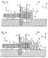
- the Fig. 1a shows a not belonging to the invention composite part 50, which is produced by means of a sewing device 100.
- the composite part 50 comprises a first skin 3, a first skin 4 and a retaining profile 2.
- the retaining profile has a groove 20 which is delimited by side walls 29 and a bottom 24 shown as a bottom. The groove extends in a first direction, which is given here by the y-direction.
- the wing thickness, the depth of the groove and the bottom thickness are measured here along the third direction z.
- the wing width, the width of the side wall and the width of the groove are measured along the second direction x.
- the first skin 3 and the second skin 4 are connected to each other before insertion of the end portions 31, 41 into the groove 20 by means of a functional seam 7.
- the functional seam 7 is introduced by the stitching of a yarn and defines the right side of the functional seam 7 lying end portions 31, 41 and the left
- the functional seam 7 helps to insert the first and second skin and is optional to the first functional seam 70 and to the second functional seam 71.
- the retaining profile 2 also has two adjoining the side walls 29 and each having a first wing 21 and a second wing 22 opposite the first wing 21, which adjoin the open end of the groove.
- the retaining profile is guided and held by means of a throat plate 16 with the skins 3, 4 introduced in the groove.
- the sewing device 100 has a feed dog 18 arranged on the throat plate 16.
- the throat plate 16 has a channel 17 for guiding a wing of the holding profile.
- the first wing 21 is guided in the channel 17.
- the guided by the conveyor 18 holding profile is guided in the region of a first needle 13 'and a second needle 14' of the sewing device 100, wherein the first needle 13 'for introducing the first functional seam 70 and the second needle 14' for introducing the second functional seam 71 is formed.
- the retaining profile 2 has the wings 21, 22, it is not necessary to connect the sections of the skins with the corresponding wings. In the Figures 3 and the following is devoted to the introduction of decorative stitching.
- the Fig. 2a shows a composite part 1, which was prepared according to a variant of the method according to the invention.
- the composite part 1 has a retaining profile 2, a first skin 3, a second skin 4 and a first seam 5 and a second seam 6.
- the first seam 5 and the second seam 6 are hereinafter referred to as decorative seams.
- a functional seam 7 connecting the first skin 3 and the second skin 4 is shown.
- the functional seam 7 is arranged such that it separates the end sections 31 and 41 of the first skin 3 and second skin 4 and the sections 32 and 42 of the first skin 3 and second skin 4, respectively.
- the holding profile 2 has a groove 20 into which the end portions 31 and 41 are inserted.
- the functional seam 7 is arranged such that it lies within the groove 20.
- a first wing 21 and a second wing 22 close.
- the groove 20 extends in the first direction, which in the present case the y-direction is.
- the composite part 1 is thus shown in cross section of the xz plane.
- the first seam 5 and the second seam 6 are introduced, whereby a connection between the first skin 3 and the first wing 21 and the second skin 4 and the second Wing 22 is made.
- the seam is a seam of yarn, which engages behind the respective wing at least in sections.
- a needle of a sewing device which introduces the first or second seam penetrates the first wing 21 and the second wing 22, respectively, so that the respective seam engages behind the respective wing at least in sections.
- a previous material connection between the first and second skin and the retaining profile 2 is not necessary, but may be present.
- the functional seam 7 was introduced and then cut with the aid of a cutting tool, the end portions 31 and 41 to a length of 1 mm.
- the end portions 31, 41 are shortened so that they do not touch the bottom of the groove, so that no bulge is visible.
- the composite part 1 of Fig. 2a Each has only one connected to the first wing 21 and second wing 22 layer of the first skin 3 and second skin 4.
- the view of a two-ply skin in the area of the suture can be achieved either by a surplus of the skin or a corresponding embodiment of the first and second wing.
- the wings can taper away from the groove.
- the composite part 1 ' has the composite part 1, which is arranged on a carrier 8.
- a transition between the carrier 8 and the retaining profile 2 is not visible or noticeable.
- the upper side is in this case the side of the carrier 8 facing the visible side S.
- the Fig. 3a shows a composite part 1, which was prepared according to a variant of the method according to the invention.
- the composite part 1 has the retaining profile 2, the first skin 3, the second skin 4 and a first seam 5 and a second seam 6.
- the first seam 5 and the second seam 6 are hereinafter referred to as decorative seams.
- a functional seam 7 connecting the first skin 3 and the second skin 4 is shown.
- the first functional seam 70 as in the description of FIGS. 1 introduced.
- the first functional seam 70 is arranged below the functional seam 7.
- the Fig. 3b merely shows an alternative arrangement of the first functional seam 70 and the composite part used in a carrier 8.
- the holding profile 2 is shown in a three-dimensional representation.
- the first wing 21 and the second wing 22 each have slits 25 extending along the x-axis.
- the slots 25 By incorporating the slots 25 in the wings, it is particularly easy to follow curvatures of the coating formed from a first skin and second skin. In particular, small radii of curvature can be realized.
- the groove 20 of the retaining profile 2 is substantially rectangular, other geometries may be used. Thus, for example, lying in the negative z-direction bottom of the groove 20 is formed rounded be, or the side walls of the groove, which extend along the z-axis, can be inclined to each other, so that the groove assumes a triangular shape.
- the groove should have a geometric shape, so that a possibly introduced functional seam 7 is still visible from the visible side.
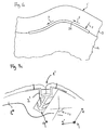
- FIG. 4b An alternative geometry of a holding profile is in the Fig. 4b shown.
- the retaining profile 2 ' has a groove 20' extending in a first direction, wherein the groove 20 'is again rectangular. Furthermore, the retaining profile 2 'has two wings 21' and 22 'adjoining the side walls of the groove 20', wherein the wings 21 'and 22' have a multiplicity of teeth 26 '.
- the function of the teeth 26 ' can be compared with that of the slots 25. It can easily be seen that, given a curvature of the retaining profile 2 'in the xy plane, the recesses of the wings 21' or 22 'due to the teeth 26' result in a simplified introduction of a curvature.
- the wings 21 'and 22' also include parts of the side walls of the groove 20 ', which is particularly illustrated by the projection 23'.
- a recess arranged in a carrier adapts to the corresponding design of the underside of the holding profile.
- rhombic cutouts can also be provided, with the axis of a rhombus preferably extending along the second direction.
- the retaining profile 2 ' is inserted into a carrier such that the pin 27' with the anchors 28 'in a second stage of a recess of a Support is anchored.
- the holding profile 2 ' is shown in cross-section perpendicular to the first direction. It can be clearly seen that the wings taper away from the groove tapering from the height H to the height h. As a result, when connecting the first and second skin, the impression of a two-ply skin is awakened for the viewer. However, the holding profile 2 'is not visible to the viewer due to the overlap by the first and second skin.
- the wing may also have a constant wall thickness, such as in the Fig. 2a shown.
- FIGS. 5a-c reference should be made to further aspects of the method, in particular in connection with an embodiment of a sewing device for introducing the decorative seams in the first and / or second wings.
- a suturing device 10 which has a needle plate 11, a first needle 13, a second needle 14 and a conveyor 15 includes.
- the throat plate 11 also has a channel 12 in which, for example, the holding profile 2 can be held and guided by means of the conveyor 15.
- the conveyor 15 transports the holding profile 2 held in the channel 12 in the direction of the first and second needle 13 and 14, respectively.
- the holding profile 2 is arranged in the channel 12 which is open in the z-direction such that the groove is likewise open in the z-direction, wherein the first and second needles 13, 14 are also aligned along the z-direction.
- the wings 21, 22 have a width along the x-direction and run as well as the introduced seams along the y-direction.
- FIG. 5a only the retaining profile 2 without the first and second skin 3 and 4 is shown.
- the presence of the skins is in the Fig. 5b shown.
- Fig. 5b which form a section IIIb through the composite part of the Fig. 5a shows, guided in the channel 12 of the needle plate 11 holding profile 2 with the not yet connected to the retaining profile 2 first skin 3 and second skin 4 are shown.
- the first skin 3 and the second skin 4 which are connected by means of the functional seam 7, held with a center guide 16 in the groove 20 of the retaining profile 2.
- the thus held in the groove 20 first skin 3 and second skin 4 is pulled by means of the conveyor 15 together with the holding profile 2 in the direction of the first needle 13 and the second needle 14.
- the corresponding seams 5 and 6 are introduced.
- FIG. 5c An alternative embodiment of a throat plate is in the Fig. 5c shown.
- the throat plate 11 ' also shown in cross section to the first direction y of the holding profile 2'. That in the FIGS. 2b and 2c shown retaining profile 2 ', a pin 27' with anchors 28 'on.
- the channel 12 'for guiding the holding profile 2' formed deeper, so that the pin 27 'is held in this without the first wing 21' and second wing 22 'from the surface of the needle plate 11' and the transporters 15 'is lifted, ie the wings 21, 22 abut the surface of the throat plate.
- FIG. 6 2 shows the underside of the first skin 3, the underside of the first skin 4 and the underside 24 of the retaining profile 2.
- the retaining profile 2 is surmounted by the composite of the first skin 3 and the second skin 4 in the first direction y, ie the direction of the course of the groove of the retaining profile 2.
- the composite part 1 "produced in this way is connected to a carrier, wherein the carrier has a As a result of this, the seam position with respect to the carrier is determined and the rejects are further reduced.
- Fig. 7a-c be different embodiments of a composite part according to the invention with a holding profile 2 as in the FIGS. 1 shown, but the functional seam 70 is not incorporated.
- the composite part 1 "'of Fig. 7a comprises a carrier 8 'made of natural fibers, which has a recess 9' for receiving the holding profile 2 " otherwise designated, the same numerals designate the same components as in the FIGS. 1 and 2 ,
- the same numerals designate the same components as in the FIGS. 1 and 2 .
- a sinking of the wings in the carrier is achieved, so that the wings close almost flush with the support surface.
- the milling must not be exactly planar, since the comparatively large contact surface of the underside of the wing compensates or corrects bumps. Even without milling, a satisfactory result is already achieved.
- the retaining profile consists of a one-piece extruded plastic profile of Shore A hardness of 55, the first and second skin 3, 4 are each made of leather. There is no further layer between the wearer and the skin. However, an additional foam layer can also be arranged as on the surface of the carrier. Suitable carrier materials are plastics such as polypropylene (PP) or glass fiber reinforced PP (PPLGF), natural fiber materials or polyurethane foams.
- PP polypropylene
- PPLGF glass fiber reinforced PP
- natural fiber materials or polyurethane foams.
- FIG. 7b A variant of a carrier 8 "of a composite part 1""is shown, which is provided outside the region of the recess with a spacer fabric 91.
- the carrier 8" itself consists of a natural fiber / plastic mixture.
- the natural fiber / plastic mixture projects as far as the visible side surface of the carrier in order to ensure sufficient stability of the recess when the holding profile is pressed into the recess Bottom of the wings directly on the natural fiber / plastic compound of the carrier.
- a further variant of a carrier 8 * is shown.
- Fig. 7c also discloses that a second direction x 'along the first direction y along which the wings extend must not be perpendicular to the mirror axis of symmetry of the holding profile, ie to the third direction z, but adapted according to the surface condition, ie the curvature of the composite part can.
- the length of a holding profile or the draft angle of the recess of the carrier is also dependent on the choice of material of the wearer. If a plastic such as PPLGF is selected as the material, the retaining profile or a journal of the retaining profile can have up to 3, preferably 2, superposed anchors and the journal can have a length between 3 mm and 10 mm. Accordingly, the depth of the recess of the carrier is chosen, which is greater than the composite length of the pin and the depth of the groove of the holding profile is.
- the draft angle can be between 90 ° +/- 30 °.
- the holding profile preferably has only one anchor, wherein the pin has a length between 2 mm and 6 mm and the depth of the recess is selected accordingly. Accordingly, the depth of the recess of the carrier is selected, which is greater than the composite length of the pin and the depth of the groove of the retaining profile.
- the draft angle can be between 90 ° +/- 15 °.
- the mass density of the carrier is less than 3000 g / m 2, preferably less than 2000 g / m 2, more preferably between 900 g / m 2 and 1400 or 1800 g / m 2.
Landscapes
- Engineering & Computer Science (AREA)
- Mechanical Engineering (AREA)
- Sewing Machines And Sewing (AREA)
- Lining Or Joining Of Plastics Or The Like (AREA)
- Vehicle Interior And Exterior Ornaments, Soundproofing, And Insulation (AREA)
Description
Gegenstand der Erfindung ist ein Verfahren zur Herstellung eines Verbundteils sowie ein Verbundteil mit einer ersten Haut, einer zweiten Haut und einem mit der ersten und zweiten Haut mittels jeweils einer Naht verbundenen Halteprofil sowie ein Halteprofil für ein derartiges Verfahren bzw. Verbundteil.The invention relates to a method for producing a composite part and a composite part having a first skin, a second skin and a holding profile connected to the first and second skin by means of a respective seam and a holding profile for such a method or composite part.
Entsprechend dem Stand der Technik besteht, insbesondere bei höherwertigen Kraftfahrzeugen, der Bedarf, Oberflächenbezüge aus hochwertigen Materialien wie etwa Leder zur Verkleidung des Innenraums zur Verfügung zu stellen. Ein derartiger Oberflächenbezug ist beispielsweise aus der, gattungsbildenden
Eine Weiterbildung findet sich in der
Ein weiteres Verbundteil wird in der
Aufgabe der vorliegenden Erfindung ist es, ein Verfahren zur Herstellung eines Verbundteils sowie ein Verbundteil, ein Halteprofil und eine im Verfahren eingesetzte Nähvorrichtung zu verbessern, so dass die aufgeführten Nachteile vermieden werden.The object of the present invention is to improve a method for producing a composite part and a composite part, a holding profile and a sewing device used in the method, so that the disadvantages listed are avoided.
Die Erfindung wird mithilfe eines Halteprofils mit den Merkmalen des Anspruchs 1, eines Verfahrens mit den Merkmalen des Anspruchs 4 sowie eines Verbundteils mit den Merkmalen des Anspruchs 12 gelöst.The invention is achieved by means of a holding profile with the features of
Verschiedene Ausführungsformen werden in den untergeordneten Ansprüchen und den Ausführungsbeispielen aufgeführt.Various embodiments are set forth in the subordinate claims and the embodiments.
Das erfindungsgemäße Verbundteil weist ein erfindungsgemäßes Halteprofil mit einer sich in einer ersten Richtung erstreckenden Nut auf, wobei jeweils ein Endabschnitt einer ersten und ein Endabschnitt einer zweiten Haut in der Nut angeordnet sind. Der Endabschnitt der ersten Haut und der Endabschnitt der zweiten Haut werden zunächst in diese sich in einer ersten Richtung erstreckende Nut des Halteprofils eingeführt. Die erste Richtung wird durch den Verlauf der Naht bestimmt, d.h. falls das Halteprofil gekrümmt wird, wird auch die erste Richtung "gekrümmt".The composite part according to the invention has a holding profile according to the invention with a groove extending in a first direction, wherein in each case an end section of a first and an end section of a second skin are arranged in the groove. The end portion of the first skin and the end portion of the second skin are first inserted into this groove extending in a first direction of the retaining profile. The first direction is determined by the course of the seam, i. if the holding profile is curved, the first direction is also "curved".
Mithilfe der Nut können die Endabschnitte der ersten und zweiten Haut gehalten und/oder geführt werden, wodurch die eigentliche Positionierung der ersten und zweiten Haut auf dem Halteprofil selbst stark vereinfacht wird. Die Nut erstreckt sich dabei vorzugsweise über die gesamte Länge des Halteprofils in der ersten Richtung. Die erste und zweite Haut können mit einer ersten Funktionsnaht verbunden sein, wobei die Funktionsnaht nur mit der ersten und zweiten Haut verbunden ist.By means of the groove, the end portions of the first and second skin can be held and / or guided, whereby the actual positioning of the first and second skin on the holding profile itself is greatly simplified. The groove preferably extends over the entire length of the holding profile in the first direction. The first and second skin may be connected to a first functional seam, wherein the functional seam is connected only to the first and second skin.
Anschließend kann das Halteprofil, welches mit einem, bevorzugt zwei, sich von dem offenen Ende der Nut und der Seitenwände aus in einer zweiten, zur ersten Richtung des Nutverlaufs im Wesentlichen senkrecht stehenden, Richtung erstreckenden Flügel ausgebildet ist, mit den verbundenen Häuten beispielsweise auf einem Träger angeordnet werden, wobei das Halteprofil mit dem Träger formschlüssig oder stoffschlüssig verbunden wird. Anschließend können die Häute auch ohne eingebrachte Zier- oder Dekornähte auf den Träger kaschiert werden. Der Verlauf der Naht ist durch die Funktionsnaht, das Halteprofil und einer zum Halteprofil korrespondierenden Ausnehmung vorgegeben. Dabei ist es bevorzugt, wenn das Halteprofil flexibel oder krümmbar ist und sich so an den Verlauf der Ausnehmung des Trägers anpasst.Subsequently, the holding profile, which is formed with one, preferably two, extending from the open end of the groove and the side walls in a second, to the first direction of Nutverlaufs substantially perpendicular, extending direction wings, with the connected skins, for example, on a Carrier can be arranged, wherein the holding profile is positively or materially connected to the carrier. Subsequently, the skins can be laminated on the carrier without any decorative or decorative seams applied. The course of the seam is predetermined by the functional seam, the retaining profile and a recess corresponding to the retaining profile. It is preferred if the holding profile is flexible or bendable and thus adapts to the profile of the recess of the carrier.
Der mindestens eine Flügel des Halteprofils dient der Verbindung zwischen einem an den Endabschnitt anschließenden Teilabschnitt der ersten bzw. zweiten Haut mit einem ersten bzw. zweiten des mindestens einen Flügels des Halteprofils mittels einer ersten bzw. zweiten Naht. Die erste und zweite Naht umfassen dabei zumindest ein Garn. Dies bedeutet insbesondere, dass die Verbindung zwischen dem Endabschnitt der ersten bzw. zweiten Haut und dem ersten bzw. zweiten Flügel derart ist, dass mindestens ein Garn den ersten bzw. zweiten Flügel von einer Sichtseite der ersten bzw. zweiten Haut aus betrachtet zumindest abschnittsweise hintergreift. Bei der ersten und zweiten Naht handelt es sich bevorzugt um Dekor- oder Ziernähte.The at least one wing of the retaining profile serves for the connection between a subsection of the first and second skin adjoining the end section and a first or second of the at least one wing of the retaining profile by means of a first or second seam. The first and second seams comprise at least one yarn. This means in particular that the connection between the end portion of the first and second skin and the first and second wings is such that at least one yarn at least partially engages behind the first and second wings from a visible side of the first and second skin , The first and second seams are preferably decorative or decorative seams.
Das Vorhandensein zweier Flügel ist notwendig, wenn eine erste bzw. zweite Naht auf beiden Seiten der Verbindungsstelle der ersten und zweiten Haut eingebracht werden soll.The presence of two wings is necessary if a first or second seam on both sides of the Junction of the first and second skin to be introduced.
Da die Endabschnitte der ersten und zweiten Haut jeweils in der Nut geführt bzw. gehalten sind, muss lediglich eine Lage der ersten bzw. zweiten Haut mit dem ersten bzw. zweiten Flügel vernäht werden. Dies reduziert die Menge des zu verwendenden Materials der ersten und zweiten Haut. Des Weiteren wird die zum Einbringen der Naht aufzuwendende Kraft verringert, da lediglich eine Lage der ersten bzw. zweiten Haut durchstoßen werden muss.Since the end portions of the first and second skin are respectively held in the groove, only one layer of the first and second skin needs to be sutured to the first and second wings, respectively. This reduces the amount of material to be used of the first and second skin. Furthermore, the force to be applied for introducing the seam is reduced since only one layer of the first or second skin has to be pierced.
Es bedarf keines vorherigen Verklebens zwischen dem Halteprofil und der ersten bzw. zweiten Haut. Auch das Mitnähen eines Nahtbandes, wie in vorhergehenden Verfahren erforderlich, kann entfallen. Aufgrund der Tiefe und der Breite der Nut können die erste bzw. zweite Haut beispielsweise leicht eingeklemmt oder locker in der Nut gehalten werden. Hierdurch ist es möglich, die Form bzw. die Optik der von der Sichtseite der ersten bzw. zweiten Haut sichtbaren Verbindungsstelle zwischen der ersten und zweiten Haut zu beeinflussen.It does not require any previous bonding between the retaining profile and the first and second skin. It is also not necessary to sew a seam band, as required in previous methods. For example, due to the depth and width of the groove, the first and second skin may be slightly pinched or loosely held in the groove. This makes it possible to influence the shape or the appearance of the visible from the visible side of the first and second skin joint between the first and second skin.
Die Flügel erlauben eine genaue Positionierung des Halteprofils in einer Ausnehmung eines Trägers und dienen als Abstands- oder Positionshalter. Mittels der Flügel ist eine exakte Abmessung der Tiefe und Breite der Ausnehmung nicht länger notwendig, da sich die Flügel einem jeweils an einer Seitenwand der Nut angebrachten und sich gegenüberliegenden Flansch gleichend auf der sich neben der Ausnehmung befindenden und diese begrenzenden Oberfläche des Trägers abstützen.The wings allow accurate positioning of the retaining profile in a recess of a carrier and serve as a distance or position holder. By means of the wings, an exact dimension of the depth and width of the recess is no longer necessary, since the wings are supported on a respective side wall of the groove mounted and opposing flange on the next to the recess and this limiting surface of the support.
Da die Flügel eine Materialstärke bzw. Flügelstärke aufweisen, welche kleiner als die Tiefe der Nut ist und im Bereich von weniger als 1,5 mm, vorzugsweise von weniger als 1 mm, liegt, fällt die leichte Erhebung des Halteprofils aus der Oberfläche des Trägers, welche durch den Flügel verursacht wird, nicht merklich ins Gewicht. Somit kann mit Hilfe der Flügel eine genaue, einfach zu erlangende und im Erscheinungsbild unauffällige Positionierung des Naht- bzw. Nutverlaufs erreicht werden. Die oder der Flügel sind als Erhebung insbesondere dann, wenn eine erste und eine zweite Haut im Halteprofil angeordnet sind und den Flügel sichtseitig überdecken, im Wesentlichen nicht erkennbar. Somit wird ein im Wesentlichen planer Abschluss zwischen einer sichtseitigen Trägeroberfläche und dem in einer Ausnehmung des Trägers angeordneten Halteprofil ohne aufwendige Justage bewirkt.Since the wings have a material thickness which is smaller than the depth of the groove and in the range of less than 1.5 mm, preferably less than 1 mm, the slight elevation of the holding profile falls from the surface of the carrier, which is caused by the wing, not noticeably in the weight. Thus, with the help of the wings an accurate, easy to obtain and inconspicuous in the appearance positioning of the seam or Nutverlaufs can be achieved. The wing or wings are as a survey, especially when a first and a second skin are arranged in the retaining profile and the wing overlap the visible side, not substantially recognizable. Thus, a substantially planar conclusion between a visible side surface and the support arranged in a recess of the support profile without complicated adjustment is effected.
Mit Hilfe des erfindungsgemäßen Profils und des erfindungsgemäßen Verbundteils ist eine Zeitersparnis zwischen 20% und 80% gegenüber herkömmlichen Verfahren zur Herstellung eines Verbundteils nach dem Stand der Technik erreichbar.With the help of the profile according to the invention and the composite part according to the invention a time savings between 20% and 80% over conventional methods for producing a composite part according to the prior art can be achieved.
Weitere Ausführungsformen können den untergeordneten Ansprüchen entnommen werden.Further embodiments may be taken from the subordinate claims.
In einer Ausführungsform der Erfindung hintergreift eine zusätzlich zu einer ersten in den Flügel eingebrachten Naht erste Funktionsnaht mindestens eine Seitenwand der Nut des Halteprofils. Hierdurch wird eine formschlüssige Verbindung zwischen der ersten und/oder zweiten Haut und dem Halteprofil hergestellt. Prozesstechnisch ist es besonders einfach, wenn die erste Funktionsnaht zwei sich gegenüberliegende und die Nut begrenzende Seitenwände hintergreift, wobei die erste und die zweite Haut durch die erste Funktionsnaht zumindest punktuell durchstoßen werden.In one embodiment of the invention engages in addition to a first introduced into the wing seam first functional seam at least one side wall of the groove of the retaining profile. As a result, a positive connection between the first and / or second skin and the holding profile is produced. In terms of process technology, it is particularly simple if the first functional seam is located opposite two and engages behind the groove limiting side walls, wherein the first and the second skin are pierced at least selectively by the first functional seam.
In einer weiteren Ausführungsform weist das Verbundteil eine zweite die erste und zweite Haut verbindende Funktionsnaht auf, welche von einer Sichtseite des späteren auf einen Träger angeordneten Verbundteils oberhalb der ersten Funktionsnaht angeordnet ist. Oberhalb bedeutet hierbei, dass die zweite Funktionsnaht von der Sichtseite her betrachtet näher liegt als die erste Funktionsnaht. Die zweite Funktionsnaht ist für den Betrachter sichtbar angeordnet und wird von einem Betrachter als die eigentliche die erste und zweite Haut verbindende Funktionsnaht wahrgenommen, da die unterhalb dieser zweiten Funktionsnaht liegende erste Funktionsnaht von der zweiten Funktionsnaht überdeckt wird. Die erste und die zweite Funktionsnaht können im Wesentlichen gleichzeitig oder innerhalb eines einzigen Arbeitsgangs eingebracht werden, was den Arbeitsaufwand reduziert.In a further embodiment, the composite part has a second functional seam connecting the first and second skin, which is arranged above the first functional seam from a visible side of the later composite part arranged on a carrier. Above this means that the second functional seam, viewed from the visible side, is closer than the first functional seam. The second functional seam is visibly arranged for the viewer and is perceived by a viewer as the actual functional seam connecting the first and second skin, since the first functional seam lying below this second functional seam is covered by the second functional seam. The first and the second functional seam can be introduced substantially simultaneously or within a single operation, which reduces the workload.
Prozesstechnisch ist es bevorzugt, wenn die erste und die zweite Haut mit einer zwischen dem Teilabschnitt und dem Endabschnitt angeordneten Funktionsnaht miteinander verbunden werden, wobei die Verbindung vorzugsweise vor dem Einführen der Endabschnitte in die Nut hergestellt wird. Hierdurch kann insbesondere die Zeit, welche zum Einbringen der ersten und zweiten Haut in die Nut benötigt wird, reduziert werden. Zudem kann die Funktionsnaht derart in der Nut liegend angeordnet werden, dass die Funktionsnaht zumindest ansatzweise als Verbindung zwischen der ersten und zweiten Haut von der Sichtseite der ersten und zweiten Haut her sichtbar ist.In terms of process technology, it is preferable if the first and the second skin are connected to one another by means of a functional seam arranged between the partial section and the end section, wherein the connection is preferably made prior to the insertion of the end sections into the groove. As a result, in particular the time required for introducing the first and second skin into the groove can be reduced. In addition, the functional seam can be arranged lying in the groove such that the functional seam is at least partially visible as a connection between the first and second skin from the visible side of the first and second skin forth.
Die im vorhergehenden Abschnitt beschriebene Funktionsnaht ist von der im vorhergehenden Abschnitt beschriebenen erste und zweiten Funktionsnaht verschieden, da sie unabhängig von diesen eingebracht werden, bevor die erste und zweite Haut in die Nut geführt werden.The functional suture described in the previous section is different from the first and second sutures described in the previous section, since they are introduced independently of them, before the first and second skin are guided into the groove.
Bevorzugt weisen die Endabschnitte der ersten bzw. zweiten Haut eine Länge von 0,5 mm bis 3 mm auf. In einer weiteren Ausführungsform weist die Nut eine Tiefe zwischen 1 mm und 4 mm, vorzugsweise zwischen 1,2 mm und 2,5 mm, auf und kann die Endabschnitte und die Funktionsnaht aufnehmen, ohne dass die Endabschnitte den Boden der Nut berühren. Hierdurch werden Aufwellungen der ersten und zweiten Haut im Bereich der Nut vermieden. Die Endabschnitte können jedoch auch derart in die Nut eingeführt sein, dass einer oder beide Endabschnitte am Boden der Nut aufliegen.Preferably, the end portions of the first and second skin have a length of 0.5 mm to 3 mm. In a further embodiment, the groove has a depth between 1 mm and 4 mm, preferably between 1.2 mm and 2.5 mm, and can accommodate the end portions and the functional seam without the end portions touching the bottom of the groove. As a result, bulges of the first and second skin in the region of the groove are avoided. However, the end portions may also be inserted into the groove such that one or both end portions rest on the bottom of the groove.
Nachfolgend werden bevorzugte Materialstärken der Komponenten des Halteprofils angegeben.Hereinafter, preferred material thicknesses of the components of the holding profile are specified.
Die Flügelstärke bzw. Wandstärke der Flügel beträgt zwischen 0,05mm und 1mm, vorzugsweise zwischen 0,2mm und 0,6mm und besonders vorzugsweise zwischen 0,35mm und 0,5mm. Die Wandstärke wird hierbei in derselben Richtung wie die Tiefe der Nut gemessen, d.h. einer im Wesentlichen senkrecht zur ersten Richtung und von der zweiten Richtung verschiedene, bevorzugt im Wesentlichen senkrecht zur zweiten Richtung stehenden, dritten Richtung gemessen.The wing thickness or wall thickness of the wings is between 0.05 mm and 1 mm, preferably between 0.2 mm and 0.6 mm and particularly preferably between 0.35 mm and 0.5 mm. The wall thickness is in this case measured in the same direction as the depth of the groove, i. a substantially perpendicular to the first direction and from the second direction different, preferably substantially perpendicular to the second direction, third direction measured.
Die Wandstärke wird bevorzugt derart gewählt, dass die maximale Haltekraft einer den Flügel und eine Haut verbindenen Naht größer ist als die zum Abriss eines Flügels in die dritte Richtung gerichteten Reißkraft. Dies birgt Vorteile beim Versuch des Herausziehens eines Halteprofils aus einer Ausnehmung eines Trägers (z.B. bei nachträglich erkannter Qualitätsmängel), da bei zu großer Belastung das wesentlich kostengünstigere Halteprofil vor der Ziernaht reißt und die Haut nicht beschädigt wird. Als maximale Reißkraft wird beispielsweise eine Reißkraft von 15N ausgewählt, d.h. wirkt ein Zug von mehr als 15 N auf einen Flügel reißt dieser vom Halteprofil ab.The wall thickness is preferably selected such that the maximum holding force of a seam connecting the wing and a skin is greater than that for demolition of a wing in the third direction tearing force. This has advantages when trying to pull out a retaining profile from a recess of a wearer (eg in subsequently recognized quality defects), since too much stress tears the much cheaper retaining profile before the decorative stitching and the skin is not damaged. For example, a breaking force of 15N is selected as the maximum breaking force, ie a pull of more than 15 N on a wing tears it off the retaining profile.
Die Breite eines Flügels entlang der zweiten Richtung beträgt gemessen von der Innenseite der Seitenwand der Nut zum äußeren Rand des Flügels hin zwischen 2mm und 7mm, bevorzugt zwischen 2,5mm und 5mm. Die Wandstärke einer die Nut begrenzenden Seitenwand entlang der zweiten Richtung beträgt zwischen 0,2mm und 2mm, wobei die Breite des Flügels derart gewählt ist, dass dieser sich flanschartig an die Seitenwand anschließt, d.h. der Flügel breiter als die Breite der Seitenwand ist. Und so als Flansch dienen kann. Die Breite der Nut entlang der zweiten Richtung beträgt gemessen zwischen den die Nut begrenzenden Innenseiten der Seitenwände zwischen 1mm und 4mm, bevorzugt zwischen 1,5mm und 3mm. Der die Nut nach unten hin begrenzende Boden weist eine Dicke im Bereich zwischen 0,1 mm und 2mm auf. Eine von der Außenseite der Seitenwände gemessene Breite der Nut beträgt somit zwischen 1,4mm und 8mm.The width of a wing along the second direction, measured from the inside of the side wall of the groove to the outer edge of the wing towards between 2mm and 7mm, preferably between 2.5mm and 5mm. The wall thickness of a groove bounding the sidewall along the second direction is between 0.2mm and 2mm, with the width of the wing chosen to be flanged to the sidewall, i. the wing is wider than the width of the side wall. And so can serve as a flange. The width of the groove along the second direction is measured between the groove bounding inner sides of the side walls between 1mm and 4mm, preferably between 1.5mm and 3mm. The bottom of the groove delimiting bottom has a thickness in the range between 0.1 mm and 2mm. A measured from the outside of the side walls width of the groove is thus between 1.4mm and 8mm.
In einer weiteren Ausführungsform, insbesondere in Hinblick auf die industrielle Herstellung eines erfindungsgemäßen Verbundteils, wird das Halteprofil in einer Stichplatte einer Nähvorrichtung geführt und/oder gehalten. Die Stichplatte weist dabei einen sich in der ersten Richtung erstreckenden Kanal zur Führung des Halteprofils auf. Die Nähvorrichtung weist zudem zwei Nadeln auf, wobei sich der Kanal zur Führung des Halteprofils zwischen den zwei Nadeln erstreckt. Die erste Nadel bringt die erste Funktionsnaht ein, wohingegen die zweite Nadel die zweite Funktionsnaht einbringt. Bevorzugt hintergreift lediglich die erste Funktionsnaht die Seitenwände der Nut. Die zweite Funktionsnaht hintergreift dementsprechend nur die erste und zweite Haut. Die zweite Nadel wird dazu in einem geringen Abstand von vorzugsweise weniger als 2mm an der offenen Seite der Nut entlang geführt.In a further embodiment, in particular with regard to the industrial production of a composite part according to the invention, the retaining profile is guided and / or held in a throat plate of a sewing device. The throat plate has a channel extending in the first direction Guide the holding profile on. The sewing apparatus also has two needles, with the channel for guiding the holding profile extending between the two needles. The first needle introduces the first functional seam, whereas the second needle introduces the second functional seam. Preferably, only the first functional seam engages behind the side walls of the groove. Accordingly, the second functional seam only engages behind the first and second skin. The second needle is guided for this purpose at a small distance of preferably less than 2 mm along the open side of the groove.
Mithilfe der vorgenannten Stichplatte kann die Prozessgeschwindigkeit zum Herstellen eines Verbundteils aus einer ersten und zweiten Haut, welche mit einem Halteprofil über mindestens eine in der Nut angeordnete erste Funktionsnaht deutlich erhöht werden, wobei die vorgegebenen Toleranzwerte wie oben beschrieben eingehalten werden können. Optional kann zeitnah oder zeitgleich eine zweite Funktionsnaht mittels einer zweiten Nadel eingebracht werden.By means of the aforesaid stitch plate, the process speed for producing a composite part of a first and second skin, which are significantly increased with a holding profile via at least one first functional seam arranged in the groove, wherein the predetermined tolerance values can be maintained as described above. Optionally, a second functional seam can be introduced by means of a second needle in a timely or simultaneous manner.
In einer weiteren Ausführungsform werden die Endabschnitte der ersten und zweiten Haut mithilfe einer Mittenführung in die Nut des Halteprofils geführt und/oder in der Nut des Halteprofils gehalten. Die Verwendung einer Mittenführung, insbesondere einer beim Vorliegen einer Funktionsnaht verwendeten Nahtmittenführung, zwischen der ersten und zweiten Haut bietet sich insbesondere im Hinblick auf die maschinelle Herstellung der ersten und zweiten Naht an. Die Mittenführung wird dabei so eingestellt, dass die erste und zweite Haut sicher in der Nut gehalten sind, so dass ein anschließendes Einbringen der ersten und zweiten Naht mit einem geforderten Toleranzwert von ±1 mm, vorzugsweise ±0,5 mm, stattfinden kann. Die Mittenführung drückt dabei von der offenen Seite der Nut her die erste und zweite Haut bzw. deren Endabschnitte in die Nut.In a further embodiment, the end sections of the first and second skin are guided by means of a center guide into the groove of the retaining profile and / or held in the groove of the retaining profile. The use of a center guide, in particular a seam center guide used in the presence of a functional seam, between the first and second skin is particularly suitable with regard to the mechanical production of the first and second seams. The center guide is adjusted so that the first and second skin are held securely in the groove, so that a subsequent introduction of the first and second seam with a required tolerance value of ± 1 mm, preferably ± 0.5 mm. The center guide presses the first and second skin or their end portions into the groove from the open side of the groove.
In einer weiteren Ausführungsform und insbesondere auf die maschinelle Herstellung eines erfindungsgemäßen Verbundteils gerichtet wird das Halteprofil in einer Stichplatte einer Nähvorrichtung geführt und/oder gehalten. Die Stichplatte weist dabei einen sich in der ersten Richtung erstreckenden Kanal zur Führung des Halteprofils auf. Die Nähvorrichtung weist zudem zwei Nadeln auf, wobei sich der Kanal zur Führung des Halteprofils zwischen den zwei Nadeln erstreckt. Die optionale Mittenführung wird zwischen den beiden Nadeln mittig im Kanal zur Führung des Halteprofils angeordnet, so dass eine optionale Mittenführung ebenfalls mittig in die Nut des Halteprofils eingreifen kann. Mithilfe der vorgenannten Stichplatte kann die Prozessgeschwindigkeit zum Herstellen eines Verbundteils aus einer ersten und zweiten Haut, welche mit einem Halteprofil mittels einer ersten und zweiten Naht verbunden werden, deutlich erhöht werden, wobei die vorgegebenen Toleranzwerte wie oben beschrieben eingehalten werden können.In a further embodiment and directed in particular to the machine production of a composite part according to the invention, the holding profile is guided and / or held in a throat plate of a sewing device. The throat plate has a channel extending in the first direction for guiding the holding profile. The sewing apparatus also has two needles, with the channel for guiding the holding profile extending between the two needles. The optional center guide is arranged centrally between the two needles in the channel for guiding the holding profile, so that an optional center guide can also engage centrally in the groove of the holding profile. By means of the aforementioned stitch plate, the process speed for producing a composite part of a first and second skin, which are connected to a holding profile by means of a first and second seam, can be significantly increased, wherein the predetermined tolerance values can be maintained as described above.
In einer weiteren Ausführungsform überragt die erste und zweite mit dem Halteprofil verbundene Haut das Halteprofil in der ersten Richtung. Dies bedeutet, dass das Halteprofil kürzer ist als die zwischen der ersten und zweiten Haut entstehende Verbindungslinie, wobei die Verbindungslinie vorzugsweise durch eine Funktionsnaht gegeben ist. Hierdurch wird es beim späteren Anordnen des Verbundteils auf einem Träger leichter, die das Halteprofil überragenden Randbereiche der ersten und zweiten Haut mit dem Träger entsprechend zu verbinden. Um beim Verfahren zur Herstellung des Verbundteils das Überragen der ersten und zweiten Haut zu gewährleisten, werden zunächst die erste und zweite Haut derart in ein erstes Ende des Halteprofils eingeführt, dass die erste und zweite Haut das erste Ende bereits zu Beginn eines Nähvorgangs überragen. Anschließend wird das Halteprofil beispielsweise in eine erfindungsgemäße Nähvorrichtung eingelegt und eine erste und zweite Naht zur Verbindung des Halteprofils mit der ersten und zweiten Haut eingebracht.In a further embodiment, the first and second skin connected to the retaining profile projects beyond the retaining profile in the first direction. This means that the holding profile is shorter than the connecting line formed between the first and second skin, wherein the connecting line is preferably given by a functional seam. In this way, when the composite part is later arranged on a carrier, it becomes easier for the edge regions of the first and second skin which project beyond the holding profile to correspond to the carrier connect to. In order to ensure the protrusion of the first and second skin in the method for producing the composite part, first the first and second skin are introduced into a first end of the retaining profile in such a way that the first and second skin already project beyond the first end at the beginning of a sewing process. Subsequently, the retaining profile is inserted, for example, in a sewing device according to the invention and introduced a first and second seam for connecting the holding profile with the first and second skin.
In einer weiteren Ausführungsform wird nach dem Verbinden der Teilabschnitte der ersten und zweiten Haut mit dem Halteprofil dieses in eine Ausnehmung eines Trägers derart eingesetzt, dass die erste und zweite Ziernaht von der Sichtseite her sichtbar sind und das Halteprofil formschlüssig und/oder stoffschlüssig mit dem Träger verbunden wird. Beispielsweise ist es möglich, die der Innenseite der Nut abgewandte Unterseite des Halteprofils mit einem Kleber zu versehen und so eine stoffschlüssige Verbindung mit dem Träger herbeizuführen. Andererseits ist es auch möglich, das Halteprofil in eine entsprechende Ausnehmung des Trägers einzuklipsen.In a further embodiment, after connecting the subsections of the first and second skin to the retaining profile, the latter is inserted into a recess of a carrier such that the first and second decorative seams are visible from the visible side and the retaining profile is positively and / or materially bonded to the carrier is connected. For example, it is possible to provide the inside of the groove facing away from underside of the retaining profile with an adhesive and thus bring about a material connection with the carrier. On the other hand, it is also possible einzuklipsen the holding profile in a corresponding recess of the carrier.
Dabei weist das Halteprofil vorzugsweise an einer dem Träger zugewandten Unterseite einen Zapfen auf, wobei der Zapfen in die Ausnehmung des Trägers eingreift und vorzugsweise mindestens einen Anker zur verbesserten Halterung des Halteprofils aufweist. Mithilfe eines Ankers kann eine verbesserte formschlüssige Klemmwirkung des Zapfens in der Ausnehmung des Trägers erreicht werden. Hierbei ist es möglich, dass die Ausnehmung des Trägers gestuft ist, d. h. eine erste Stufung das eigentliche Halteprofil aufnimmt und die zweite weiter in den Träger ragende Stufung den Zapfen aufnimmt.In this case, the retaining profile preferably has a pin on a underside facing the carrier, wherein the pin engages in the recess of the carrier and preferably has at least one armature for improved retention of the retaining profile. By means of an anchor, an improved positive clamping action of the pin can be achieved in the recess of the wearer. In this case, it is possible for the recess of the carrier to be stepped, ie for a first step to pick up the actual holding profile and the second step further projecting into the carrier receives the pin.
Ein etwaiger Zapfen weist entlang der im vorhergehenden Abschnitt beschriebenen dritten Richtung von der Unterseite des Bodens der Nut an gemessen ein Länge zwischen 2mm und 6mm auf. An dem Zapfen angeordnete Anker weisen eine in der zweiten Richtung gemessene Breite auf, welche vorzugsweise derart gewählt ist, dass ein Ankerarm des Ankers die Außenseite der Seitenwand der Nut zwischen 0,1mm und 1mm, überragt.Any stud, as measured along the third direction described in the previous section, measured from the bottom of the bottom of the groove has a length between 2mm and 6mm. Anchors arranged on the pin have a width measured in the second direction, which is preferably chosen such that an anchor arm of the anchor projects beyond the outside of the side wall of the groove between 0.1 mm and 1 mm.
In einer weiteren Ausführungsform weisen die mindestens zwei Flügel des Halteprofils eine Vielzahl von Zähnen und/oder Schlitzen auf. Alternativ können in den Flügel rhombenförmige Ausschnitte eingebracht werden. Hierbei verlaufen die Zähne bzw. die Schlitze oder Rhombenausschnitte der Flügel quer zur ersten Richtung der Nut. Aufgrund der Schlitze bzw. der Zähne ist es möglich, das Halteprofil entsprechend leicht zu krümmen, wobei Krümmungsradien bis zu 30 mm möglich sind. Hierdurch kann auf einfache Weise ein komplizierter Nahtverlauf, welcher Krümmungen aufweist, erstellt werden. Die Geometrie des Nahtverlaufs wird dabei durch den Zuschnitt der ersten und zweiten Haut vorgegeben.In a further embodiment, the at least two wings of the holding profile have a multiplicity of teeth and / or slots. Alternatively, rhombic cut-outs can be introduced into the wing. Here, the teeth or the slots or rhombic sections of the wings extend transversely to the first direction of the groove. Due to the slots or the teeth, it is possible to curve the holding profile according to easily, with radii of curvature up to 30 mm are possible. As a result, a complicated seam course, which has curvatures, can be created in a simple manner. The geometry of the seam course is predetermined by the cut of the first and second skin.
Es ist bevorzugt, wenn das Halteprofil aus einem vorzugsweise extrudierten Kunststoff besteht und eine Shore-Härte zwischen 25 und 100, vorzugsweise zwischen 40 und 70, aufweist. Ein aus einem dementsprechenden Kunststoff hergestelltes Halteprofil weist die notwendige Weichheit zum Erstellen komplizierter gekrümmter Nahtverläufe auf. Zudem ist es mittels des Extrusionsverfahrens möglich, beliebig lange Halteprofile herzustellen, wobei die erste Richtung des Halteprofils im Wesentlichen mit der Extrusionsrichtung übereinstimmt.It is preferred if the holding profile consists of a preferably extruded plastic and has a Shore hardness between 25 and 100, preferably between 40 and 70. A holding profile made of a corresponding plastic has the necessary softness to create complicated curved seam courses. In addition, it is possible by means of the extrusion process to produce any desired length retaining profiles, wherein the first direction of the Holding profile substantially coincides with the extrusion direction.
Besonders bevorzugt ist eine Shore A Härte des Halteprofils von > 50, wenn die erste und/oder zweite Haut eine Shore A Härte von < 50 besitzen, um die Sicherheitsauflagen zur Vermeidung von Kopfverletzungen zu erfüllen. Die Messung der Shore A Härte kann mittels eines dynamischen Tests nach der Norm European "Commision for Europe (ECE) R21 Annex 4" vorgenommen werden.Particularly preferred is a Shore A hardness of the holding profile of> 50, if the first and / or second skin have a Shore A hardness of <50 to meet the safety requirements for the prevention of head injuries. The measurement of the Shore A hardness can be carried out by means of a dynamic test according to the standard European "Commision for Europe (ECE)
Alternativ können die Flügel des Halteprofils über Textil-, Vlies- oder Gewirkefahnen realisiert sein, im Gegensatz zu einem einstückig mittels Extrusion hergestellten Halteprofils. Die Flügel werden dabei beispielsweise angeklebt oder angeschweißt.Alternatively, the wings of the holding profile can be realized via textile, fleece or knitted fabric flags, in contrast to a holding profile produced in one piece by means of extrusion. The wings are glued or welded, for example.
Besonders bevorzugt werden als erste und/oder zweite Haut Materialien wie Leder, Kunstleder, Kunststoffe wie z. B. Alcantara oder Gewebe oder Gewirke verwendet. Als Träger kommen Träger mit einem Abstandsgewirke, frontgeschäumte Träger oder hartkaschierte Träger aus Kunststoffen oder Gewirken in Frage, wobei der Träger eine das Halteprofil aufnehmende Schiene aufweisen kann.Particularly preferred as the first and / or second skin materials such as leather, synthetic leather, plastics such. B. Alcantara or woven or knitted fabric used. Suitable carriers are carriers with a spacer knitted fabric, front-foamed carriers or hard-laminated carriers made of plastics or knitted fabrics, wherein the carrier may have a retaining profile-receiving rail.
Eine besonders vorteilhafte Weiterbildung sieht vor, dass das Halteprofil und/oder Teile der Endabschnitte in einem definierten Abstand zum Verlauf der ersten Funktionsnaht gekürzt werden.A particularly advantageous embodiment provides that the holding profile and / or parts of the end portions are shortened at a defined distance from the course of the first functional seam.
Dieses Kürzen kann parallel zum Einbringen von Funktionsnähten oder auch nachfolgend erfolgen.This shortening can be done parallel to the introduction of functional seams or also below.
In einer bevorzugten Ausführungsform wird, wie in
Diese Nähmaschine ist so gestaltet, dass sie eine Stichplatte aufweist mit einem Transporteur zum Weitertransport des Bauteils beim Nähen. Außerdem kann zusätzlich (oder alternativ zu einem Transporteur) ein Transportrad vorgesehen sein.This sewing machine is designed so that it has a needle plate with a feed dog for further transport of the component during sewing. In addition, in addition (or as an alternative to a transporter) a transport wheel may be provided.
Essentiell ist jedoch, dass zumindest eine Nadel vorgesehen ist, die das Halteteil mit den beiden Endabschnitten verbindet. Parallel zu dieser Naht wird dann ein Schnittmesser geführt (s. auch
Eine entsprechende Nähmaschine würde also enthalten: mindestens eine Nadel zum Einbringen jeweils einer Naht sowie einer Stichplatte zum Führen eines zu erstellenden Verbundteils, wobei die Nähvorrichtung eine Nadel aufweist zur Verbindung eines Halteteils einerseits mit zwei Enden eines Dekorteils andererseits. Zum Transport kann hierbei ein Rad gegeben sein, welches auf dem oberen der beiden Endabschnitte abrollt, alternativ ein Transporteur (dies bevorzugt bei Ausführungsvarianten, bei denen die Halteelemente und/oder die Endabschnitte noch "Flügel" haben).A corresponding sewing machine would therefore contain: at least one needle for introducing a respective seam and a throat plate for guiding a composite part to be created, wherein the sewing device has a needle for connecting a holding part on the one hand with two ends of a decorative part on the other. For transport, in this case a wheel can be given, which is on the upper of the two end portions rolls, alternatively a transporter (this is preferred in embodiments in which the holding elements and / or the end sections still have "wings").
Diese Ausführungsform des Verbundteils hat Vorteile, da das Ende des Retainers (Halteprofils) während des Nähprozesses bzw. nachfolgend beschnitten wird, um eine exakte Gesamthöhe zu erreichen. Hierdurch ergibt sich eine maßmäßig exakte und außerdem gerade und fluchtende Positionierung in einem entsprechenden Träger. Hierdurch wird einerseits das äußere Erscheinungsbild eines späteren Verbundteils sehr ansehnlich. Insbesondere wird allerdings auch die Gesamthöhe beschränkt bzw. kommt es nicht notwendigerweise zu einer Erhöhung im Bereich der Naht, so dass entsprechend Bauraum gespart werden kann.This embodiment of the composite part has advantages in that the end of the retainer (retaining profile) is trimmed during the sewing process or subsequently in order to achieve an exact overall height. This results in a dimensionally accurate and also straight and aligned positioning in a corresponding carrier. As a result, on the one hand, the external appearance of a later composite part is very attractive. In particular, however, the overall height is limited or it does not necessarily increase in the seam, so that space can be saved accordingly.
In einer weitergehenden Ausführungsform kann noch eine zweite Naht vorgesehen sein, und zwar auf der von dem Beschnitt abweisenden Seite. Diese Naht verbindet lediglich zwei Endabschnitte kurz oberhalb bzw. fluchtend mit einer Oberkante des Haltemittels. Diese Naht hat die Aufgabe, eine Funktionsnaht sichtbar zu machen und den optischen Eindruck der Funktionsnaht zu wahren. Es würde auch ausreichen, lediglich nur die dem Beschnitt nähere Naht vorzusehen, allerdings würde dann das optische Nahtbild nicht mehr sichtbar sein. Mit dieser neuen Technologie wird ein Toleranzfeld von +/-0,5 mm erreicht. Besondere Vorteile liegen darin, dass die Ausschussrate geringer wird, enge Radien (Biegungen in der Nahtlängsachse mit bis zu weniger als r = 20 mm Krümmungsradius) sind möglich. Dabei werden bevorzugt Krümmungsradien im Bereich zwischen ca. 40mm und 60mm angestrebt, da dies eine besonders gelungene Haptik aufweist. Konkave und konvexe Bereiche sind ebenfalls möglich, das Halteprofil ist universell anwendbar bei Verbundteilen, die schubweich sind (Abstandsgewirke), frontgeschäumten Trägern bzw. hartkaschierten Trägern.In a further embodiment, a second seam can still be provided, on the side facing away from the trim. This seam connects only two end portions just above or in alignment with an upper edge of the holding means. This seam has the task to make a functional seam visible and to preserve the visual impression of the functional seam. It would also be sufficient merely to provide only the seam closer to the trimming, but then the optical seam pattern would no longer be visible. With this new technology, a tolerance field of +/- 0.5 mm is achieved. Particular advantages are that the reject rate is lower, narrow radii (bends in the seam longitudinal axis with up to less than r = 20 mm radius of curvature) are possible. In this case, preferred radii of curvature in the range between about 40mm and 60mm are sought, as this has a particularly successful feel. Concave and convex areas are also possible, the retaining profile is universally applicable for composite parts, which are push-soft (spacer fabric), front foamed carriers or hard-laminated carriers.
Zusammengefasst kann also gesagt werden, dass insbesondere bei begrenztem Bauraum bzw. begrenzter Tiefe der Nut von entsprechenden Trägern diese vorteilhafte Variante sinnvoll ist. Dasselbe gilt zur Minimierung von auftretenden Toleranzschwankungen durch die Positionierung der Beschnitte im Nähprozess durch den jeweiligen Bearbeiter.In summary, it can therefore be said that, in particular with limited installation space or limited depth of the groove of corresponding carriers, this advantageous variant makes sense. The same applies to the minimization of tolerance variations occurring due to the positioning of the cuts in the sewing process by the respective operator.
Als Lösungsansatz wird also zum Toleranzausgleich der Zuschnittspositionierung durch die Beschnitteinrichtung ein festes Maß ausgeglichen / korrigiert. Der Verbund aus Profil (Keder) / Dekormaterial wird im Bereich der Naht auf ein fest definiertes Längenmaß limitiert. Hierbei kann auch ein Anbringen einer Dipper-/ Wellenstruktur an den der Nut anliegenden Seiten des Profils / Keder gegeben sein.As a solution, therefore, a fixed amount is compensated / corrected for tolerance compensation of the blank positioning by the trimming device. The composite of profile (piping) / decorative material is limited to a permanently defined length in the area of the seam. In this case, attaching a dipper / wave structure to the sides of the profile / piping adjacent to the groove can also be provided.
Die Anbringung der Naht bzw. des Beschnittes kann sowohl mit einer Nähvorrichtung als Säulenmaschine oder auch als Flachbettmaschine gegeben sein.
Nachfolgend soll die Erfindung anhand einiger Ausführungsbeispiele genauer erläutert werden. Die im Rahmen der verschiedenen Ausführungsbeispiele offenbarten einzelnen Merkmale können zu weiteren Ausführungsbeispielen miteinander kombiniert werden. Es zeigen:
- Fig. 1a, 1b
- nicht zur Erfindung gehörende Ausführungsformen eines Verbundteils;
- Fig. 2a, 2b
- erfindungsgemäße Ausführungsformen eines Verbundteils;
- Fign. 3a, 3b
- weitere erfindungsgemäße Ausführungsformen eines Verbundteils;
- Fign. 4a-c
- Ausführungsformen eines Halteprofils;
- Fign. 5a-c
- verschiedene Ansichten eines Halteprofils und einer Nähvorrichtung;
- Fig. 6
- Ansicht der Unterseite einer Ausführungsform eines Verbundteils;
- Fign. 7a-c
- verschiedene erfindungsgemäße Ausführungsformen eines Verbundteils.
Below, the invention will be explained in more detail with reference to some embodiments. The individual features disclosed in the various exemplary embodiments can be combined with one another to form further exemplary embodiments. Show it:
- Fig. 1a, 1b
- not belonging to the invention embodiments of a composite part;
- Fig. 2a, 2b
- embodiments of a composite part according to the invention;
- FIGS. 3a, 3b
- further embodiments of a composite part according to the invention;
- FIGS. 4a-c
- Embodiments of a holding profile;
- FIGS. 5a-c
- different views of a holding profile and a sewing device;
- Fig. 6
- View of the underside of an embodiment of a composite part;
- FIGS. 7a-c
- various embodiments of a composite part according to the invention.
Die
Die Flügelstärke, die Tiefe der Nut sowie die Bodendicke werden vorliegend entlang der dritten Richtung z gemessen. Die Flügelbreite, die Breite der Seitenwand und die Breite der Nut werden entlang der zweiten Richtung x gemessen.The wing thickness, the depth of the groove and the bottom thickness are measured here along the third direction z. The wing width, the width of the side wall and the width of the groove are measured along the second direction x.
Die erste Haut 3 und die zweite Haut 4 werden vor dem Einführen der Endabschnitte 31, 41 in die Nut 20 mittels einer Funktionsnaht 7 miteinander verbunden. Die Funktionsnaht 7 wird durch das Vernähen eines Garns eingebracht und definiert die rechts der Funktionsnaht 7 liegenden Endabschnitte 31, 41 und die links der Funktionsnaht 7 liegenden Teilabschnitte 32, 42. Die Funktionsnaht 7 hilft beim Einführen der ersten und zweiten Haut und ist optional zur ersten Funktionsnaht 70 und zur zweiten Funktionsnaht 71.The
Das Halteprofil 2 weist zudem zwei an die Seitenwände 29 anschließende und jeweils einen ersten Flügel 21 und einen dem ersten Flügel 21 gegenüberliegenden zweiten Flügel 22 auf, welche sich an das offene Ende der Nut anschließen. Zum Einbringen der ersten Funktionsnaht 70 und der zweiten Funktionsnaht 71 wird das Halteprofil mit den in der Nut eingebrachten Häuten 3, 4 mittels einer Stichplatte 16 geführt und gehalten. Um das Halteprofil 2 zu bewegen weist die Nähvorrichtung 100 einen an der Stichplatte 16 angeordneten Transporteur 18 auf.The retaining
Die Stichplatte 16 weist einen Kanal 17 zur Führung eines Flügels des Halteprofils auf. In der
Die mittels der ersten Nadel 13' eingebrachte erste Funktionsnaht 70 hintergreift die zwei Seitenwände 29 und durchstößt die erste Haut 3 und die zweite Haut 4 punktuell, welche somit sicher in der Nut 20 gehalten sind. Die zweite Nadel 14' wird in geringem Abstand von weniger als 1mm zur offenen in der x-Richtung verlaufenden Seite der Nut geführt und verbindet lediglich die erste und zweite Haut mittels der zweiten Funktionsnaht 71, welche von der Sichtseite S aus betrachtet sichtbar ist. Obgleich das Halteprofil 2 die Flügel 21, 22 aufweist, ist es nicht notwendig die Teilabschnitte der Häute mit den entsprechenden Flügeln zu verbinden. In den
Das in der
Die
Das Halteprofil 2 weist eine Nut 20 auf, in welche die Endabschnitte 31 und 41 eingeführt sind. Auch die Funktionsnaht 7 ist derart angeordnet, dass diese innerhalb der Nut 20 liegt. An die Seitenwände der Nut 20 schließen sich ein erster Flügel 21 und ein zweiter Flügel 22 an. Die Nut 20 erstreckt sich in der ersten Richtung, welche im vorliegenden Falle die y-Richtung ist. Das Verbundteil 1 ist somit im Querschnitt der xz-Ebene gezeigt.The holding
Nachdem die Endabschnitte 31 bzw. 41 in die Nut 20 eingeführt worden sind, werden die erste Naht 5 bzw. die zweite Naht 6 eingebracht, wodurch eine Verbindung zwischen der ersten Haut 3 und dem ersten Flügel 21 bzw. der zweiten Haut 4 und dem zweiten Flügel 22 hergestellt wird. Bei der Naht handelt es sich um eine Naht aus Garn, welche den jeweiligen Flügel jeweils zumindest abschnittsweise hintergreift. Bei dem in der
Bevor die Endabschnitte 31 bzw. 41 in die Nut 20 eingeführt werden, wurde die Funktionsnaht 7 eingebracht und anschließend mithilfe eines Schnittwerkzeuges die Endabschnitte 31 bzw. 41 auf eine Länge von 1 mm gekürzt. Die Endabschnitte 31, 41 sind dabei derart gekürzt, dass diese den Boden der Nut nicht berühren, so dass keine Aufwölbung sichtbar ist.Before the
Das Verbundteil 1 der
Aufgrund der in die Nut 20 eingeführten Endabschnitte 31 bzw. 41 ist ein Vorpositionierwerkzeug mit Nahtschwert nicht länger notwendig. Hierdurch werden die Positionierzeiten der ersten und zweiten Haut auf dem Halteprofil 2 deutlich verkürzt. Da vor dem Einbringen der Ziernähte 5 und 6 keine stoffschlüssige Verbindung zwischen dem Halteprofil 2 und der ersten Haut 3 bzw. zweiten Haut 4 besteht, kann bei einer Fehlstellung die Naht 5 bzw. 6 jederzeit wieder gelöst werden. Eine endgültige Verbindung zwischen dem Halteprofil und der ersten bzw. zweiten Haut kann nach dem Einbringen der Fugentemperatur durch die jeweilige Haut erzeugt werden. Üblicherweise erfolgt dies nach dem Presskaschieren oder dem Membrankaschieren des Verbundteils mit einem Träger.Due to the introduced into the
In der
Es sei betont, dass für sämtliche der hier gezeigten Ausführungsformen ein Beschnitt des Verbundteils / des Halteprofils möglich ist. Dies gilt insbesondere für die Ausführungsform von
Die
In der
Eine alternative Geometrie eines Halteprofils ist in der
An die dem Boden der Nut 20' abgewandte Seite des Halteprofils 2' schließt sich ein Zapfen 27' mit Ankern 28' an. Nachdem die erste und zweite Haut in die Nut 20' eingeführt worden sind und die Teilabschnitte der ersten und zweiten Haut mit dem ersten bzw. zweiten Flügel 21' bzw. 22' verbunden worden sind, wird das Halteprofil 2' derart in einen Träger eingesetzt, dass der Zapfen 27' mit den Ankern 28' in einer zweiten Stufe einer Ausnehmung eines Trägers verankert wird. Beim Einbringen der Nähte, welche den ersten Flügel 21' und den zweiten Flügel 22' hintergreifen, können auch die zwischen zwei Zähnen 26' gelegenen Bereiche der die Zähne 26' überdeckenden ersten bzw. zweiten Haut mit der Naht versehen werden, wobei sie dort die Flügel 21' bzw. 22' nicht hintergreifen. Die Verbindung wird lediglich durch das Durchstoßen und Hintergreifen bzw. das ausschließliche Hintergreifen der Zähne 26' in anderen Abschnitten gewährleistet.At the bottom of the groove 20 'facing away from the holding profile 2' is followed by a pin 27 'with anchors 28' at. After the first and second skin have been inserted into the groove 20 'and the subsections the first and second skin have been connected to the first and second wings 21 'and 22', the retaining profile 2 'is inserted into a carrier such that the pin 27' with the anchors 28 'in a second stage of a recess of a Support is anchored. When introducing the seams, which engage behind the first wing 21 'and the second wing 22', the areas of the teeth 26 'covering the first and second skin between two teeth 26' can be provided with the seam, where they Do not engage behind wings 21 'and 22'. The connection is ensured only by the piercing and engaging behind or the exclusive engagement behind the teeth 26 'in other sections.
In der
Jedoch kann der Flügel auch eine konstante Wandstärke aufweisen, wie beispielsweise in der
In den nachfolgenden Erläuterungen zu den
In der
In der
Eine alternative Ausführungsform einer Stichplatte ist in der
In der
In den
Das Verbundteil 1"' der
Das Halteprofil besteht aus einem einstückig extrudierten Kunststoffprofil der Shore A Härte von 55, die erste und zweite Haut 3, 4 bestehen jeweils aus Leder. Zwischen dem Träger und der Haut ist keine weitere Schicht angeordnet. Allerdings kann auch eine zusätzliche Schaumschicht als auf der Oberfläche des Trägers angeordnet sein. Geeignete Trägermaterialien sind Kunststoffe wie Polypropylen (PP) oder glasfaserverstärktes PP (PPLGF), Naturfaserwerkstoffe oder PUR-Schäume.The retaining profile consists of a one-piece extruded plastic profile of Shore A hardness of 55, the first and
In der
In der
Das erfindungsgemäße Profil ist geeignet um Winkel zwischen der Oberfläche und einem Teil der Ausnehmung von α=90°+/-30° im obigen Sinne auszugleichen.The profile according to the invention is suitable for compensating angles between the surface and a part of the recess of α = 90 ° +/- 30 ° in the above sense.
Die
Die Länge eines Halteprofils bzw. der Entformungswinkel der Ausnehmung des Trägers ist auch abhängig von der Materialwahl des Trägers. Wird als Material ein Kunststoff wie bspw. PPLGF gewählt, so kann das Halteprofil bzw. ein Zapfen des Halteprofils bis zu 3, vorzugsweise 2 übereinanderliegende Anker aufweisen und der Zapfen eine Länge zwischen 3 mm und 10 mm aufweisen. Dementsprechend wird die Tiefe der Ausnehmung des Trägers gewählt, welche größer als die zusammengesetzte Länge des Zapfen und der Tiefe der Nut des Halteprofils ist. Der Entformungswinkel kann zwischen 90°+/-30° liegen.The length of a holding profile or the draft angle of the recess of the carrier is also dependent on the choice of material of the wearer. If a plastic such as PPLGF is selected as the material, the retaining profile or a journal of the retaining profile can have up to 3, preferably 2, superposed anchors and the journal can have a length between 3 mm and 10 mm. Accordingly, the depth of the recess of the carrier is chosen, which is greater than the composite length of the pin and the depth of the groove of the holding profile is. The draft angle can be between 90 ° +/- 30 °.
Wird als Trägermaterial, in welches die Ausnehmung eingebracht wird, ein nachwachsender Rohstoff wie Holz, Hanf, Sisal oder Flachs oder eine Mischung daraus gewählt (wobei der Rohstoff mit duroplastischen oder thermoplastischen Kunststoffen gebunden wird), so weist das Halteprofil bevorzugt lediglich einen Anker auf, wobei der Zapfen eine Länge zwischen 2 mm und 6 mm aufweist und die Tiefe der Ausnehmung entsprechend dazu gewählt wird. Dementsprechend wird die Tiefe der Ausnehmung des Trägers gewählt, welche größer als die zusammengesetzte Länge des Zapfen und der Tiefe der Nut des Halteprofils ist. Der Entformungswinkel kann zwischen 90°+/-15° liegen. Die Massenbelegung des Trägers beträgt unter 3000 g/m^2, vorzugsweise unter 2000 g/m^2, besonders vorzugsweise zwischen 900 g/m^2 und 1400 bzw. 1800 g/m^2.If a renewable raw material such as wood, hemp, sisal or flax or a mixture thereof is selected as carrier material into which the recess is introduced (the raw material being bound with thermosetting or thermoplastic plastics), the holding profile preferably has only one anchor, wherein the pin has a length between 2 mm and 6 mm and the depth of the recess is selected accordingly. Accordingly, the depth of the recess of the carrier is selected, which is greater than the composite length of the pin and the depth of the groove of the retaining profile. The draft angle can be between 90 ° +/- 15 °. The mass density of the carrier is less than 3000 g /
Claims (14)
- A holding profile (2; 2') with a groove (20; 20'), delimited by side walls (29; 29') and a base (24), for positioning a first and a second skin (3, 4), wherein the groove (20) extends in a first direction (y) and wherein a peg adjoins that side of the base (24) which is remote from the groove,
wherein a first wing (21; 21') adjoins the first side wall and a second wing (22; 22') adjoins the second side wall, and the wings extend along a second direction (x) which is substantially perpendicular to the first direction, wherein the first and second wings (21, 22; 21', 22') extend from the open end of the groove along the second direction (x), characterised in that a partial portion (32) of the first skin (3) is joined to a first (21; 21') of the at least two wings of the holding profile (2; 2') by means of a first seam (5) comprising at least one yarn, and/or
a partial portion (42) of the second skin (4) is joined to a second (22; 22') of the at least two wings of the holding profile (2; 2') by means of a second seam (6) comprising at least one yarn. - A holding profile according to Claim 1, characterised in that the peg (27') has at least one anchor (28').
- A holding profile according to one of the preceding claims, characterised in that the first and second wings have a wing thickness (21, 22; 21', 22') of between 0.05 mm and 1 mm, preferably of between 0.2 mm and 0.6 mm, and the wall thickness of the first or second wing is preferably substantially constant.
- A method for producing a composite part (1; 1'; 1"; 1"'; 1""), which comprises the following step:a) introducing an end portion (31) of a first skin (3) and an end portion (41) of a second skin (4) into a groove (20; 20'), extending along a first direction (y) and delimited by side walls (29; 29') and a base (24), of a holding profile (2; 2') which has at least two wings (21, 22; 21', 22') which adjoin the side walls and which extend from an open end of the groove along a second direction (x) substantially perpendicularly to the first direction; characterised by the further step:b) joining a partial portion (32) of the first skin (3) which adjoins the end portion (31) to a first (21; 21') of the at least two wings of the holding profile (2; 2') by means of a first seam (5) comprising at least one yarn, and/or joining a partial portion (42) of the second skin (4) which adjoins the end portion (41) to a second (22; 22') of the at least two wings of the holding profile (2; 2') by means of a second seam (6) comprising at least one yarn.
- A method according to Claim 4, characterised in that the first and the second skin (3, 4) are joined together with a functional seam (7) arranged between the respective partial portion (32, 42) and the respective end portion (31, 41), preferably are joined together before the introduction of the end portions (31, 41) into the groove (20; 20').
- A method according to one of Claims 4 or 5, characterised in that the end portions (31, 41) of the first and second skin (3, 4) have a length of between 0.5 mm and 3 mm.
- A method according to one of Claims 4 to 6, characterised in that the first and second skin (3, 4) which are joined to the holding profile (2; 2') extend beyond the holding profile (2; 2') when viewed in the first direction (y).
- A method according to one of Claims 4 to 7, characterised in that after the introduction of the first functional seam (70) into the groove (20; 20') the holding profile is inserted into a recess (9) in a support (8) and the holding profile (2; 2') is joined to the support (8) preferably in a positively locking manner and/or in a material-to-material bond.
- A method according to one of Claims 4 to 8, characterised in that the holding profile (2; 2') consists of a plastics material which has a Shore A hardness of between 25 and 100, preferably of between 50 and 100.
- A method according to one of Claims 4 to 9, characterised in that the first and/or second skin (3, 4) consists of a leather, an imitation leather, a plastics material, a woven fabric or a knitted fabric.
- A method according to one of Claims 4 to 10, characterised in that the holding profile and optionally parts of the end portions are shortened at a defined distance from the path of the first functional seam.
- A composite part (1; 1'; 1"; 1"'; 1"") with a first skin (3), a second skin (4) and a holding profile (2; 2') which is joined to the first and second skin by means of a seam, wherein
the holding profile (2; 2') has a groove (20; 20') which extends in a first direction (y), which groove is delimited by side walls (29; 29') and a base (24), wherein an end portion (31) of the first skin (3), an end portion (41) of the second skin (4) and the seam, which is formed as a first functional seam (70) preferably comprising at least one yarn, are arranged in the groove (20; 20'),
wherein the holding profile has at least one, preferably two, wing(s), wherein the at least one wing adjoins the first side wall and extends from an open end of the groove along a second direction (x) substantially perpendicular to the first direction, characterised in that a partial portion (32) of the first skin (3) is joined to a first (21; 21') of the at least two wings of the holding profile (2; 2') by means of a first seam (5) comprising at least one yarn and/or a partial portion (42) of the second skin (4) is joined to a second (22; 22') of the at least two wings of the holding profile (2; 2') by means of a second seam (6) comprising at least one yarn. - A composite part according to Claim 12, characterised in that a support (9) with a recess (8) is comprised, wherein the holding profile (2; 2') is introduced into the recess (9).
- A composite part according to Claim 13, characterised in that the recess (9) of the support (8) is formed such that the at least one wing (21, 22) lies outside the recess (9) on the surface of the support.
Priority Applications (1)
| Application Number | Priority Date | Filing Date | Title |
|---|---|---|---|
| EP10710248.5A EP2408649B1 (en) | 2009-03-18 | 2010-03-18 | Retaining profile and composite part for lining a motor vehicle interior |
Applications Claiming Priority (5)
| Application Number | Priority Date | Filing Date | Title |
|---|---|---|---|
| DE200910013863 DE102009013863A1 (en) | 2009-03-18 | 2009-03-18 | Method for manufacturing composite part, involves inserting end portion, primary skin, and end portion of secondary skin into groove of holding profile extending along direction |
| DE200910013862 DE102009013862A1 (en) | 2009-03-18 | 2009-03-18 | Method for manufacturing composite part, involves inserting end portion, primary skin, and end portion of secondary skin into groove of holding profile extending along direction |
| EP09075335.1A EP2230132B1 (en) | 2009-03-18 | 2009-07-27 | Composite part for lining a motor vehicle interior |
| PCT/EP2010/001890 WO2010105855A2 (en) | 2009-03-18 | 2010-03-18 | Holding profile and composite part for paneling motor vehicle interiors |
| EP10710248.5A EP2408649B1 (en) | 2009-03-18 | 2010-03-18 | Retaining profile and composite part for lining a motor vehicle interior |
Publications (2)
| Publication Number | Publication Date |
|---|---|
| EP2408649A2 EP2408649A2 (en) | 2012-01-25 |
| EP2408649B1 true EP2408649B1 (en) | 2016-10-12 |
Family
ID=41600793
Family Applications (2)
| Application Number | Title | Priority Date | Filing Date |
|---|---|---|---|
| EP09075335.1A Active EP2230132B1 (en) | 2009-03-18 | 2009-07-27 | Composite part for lining a motor vehicle interior |
| EP10710248.5A Active EP2408649B1 (en) | 2009-03-18 | 2010-03-18 | Retaining profile and composite part for lining a motor vehicle interior |
Family Applications Before (1)
| Application Number | Title | Priority Date | Filing Date |
|---|---|---|---|
| EP09075335.1A Active EP2230132B1 (en) | 2009-03-18 | 2009-07-27 | Composite part for lining a motor vehicle interior |
Country Status (2)
| Country | Link |
|---|---|
| EP (2) | EP2230132B1 (en) |
| WO (1) | WO2010105855A2 (en) |
Cited By (2)
| Publication number | Priority date | Publication date | Assignee | Title |
|---|---|---|---|---|
| DE102019109390A1 (en) * | 2019-04-10 | 2020-10-15 | Dr. Ing. H.C. F. Porsche Aktiengesellschaft | Interior component for a motor vehicle |
| US11628781B2 (en) | 2021-05-14 | 2023-04-18 | Faurecia Interior Systems, Inc. | Vehicle interior panel and method of manufacture |
Families Citing this family (16)
| Publication number | Priority date | Publication date | Assignee | Title |
|---|---|---|---|---|
| DE102010045719A1 (en) | 2010-09-15 | 2012-03-15 | Faurecia Innenraum Systeme Gmbh | Holding profile for composite part of e.g. headliner, utilized in automobile industry, has groove formed in profile bottom for positioning two films, where height of holding profile is decreased in bent area |
| DE102010045729A1 (en) | 2010-09-15 | 2012-03-15 | Faurecia Innenraum Systeme Gmbh | Composite part and method for producing a composite part |
| DE102010053149B4 (en) | 2010-11-30 | 2015-02-26 | Faurecia Innenraum Systeme Gmbh | Tool for positioning a skin |
| DE202010016550U1 (en) | 2010-12-09 | 2011-03-03 | Faurecia Innenraum Systeme Gmbh | Composite part with welded connection |
| DE102011119320A1 (en) | 2011-11-17 | 2013-05-23 | Faurecia Innenraum Systeme Gmbh | Holding profile for positioning a seam connecting two decorative layers as well as composite part with a holding profile |
| DE102012210734B9 (en) | 2012-06-25 | 2017-02-23 | Faurecia Innenraum Systeme Gmbh | Method for shortening a holding profile, use of a sewing device and sewing device |
| DE102014225944A1 (en) | 2014-12-15 | 2016-06-16 | Faurecia Innenraum Systeme Gmbh | Molded part, vehicle interior trim part and device and method for producing the molded part or the vehicle interior trim part |
| EP3047948B1 (en) * | 2015-01-20 | 2020-03-04 | SMP Deutschland GmbH | Leather trim model |
| DE202015002525U1 (en) * | 2015-04-08 | 2015-05-28 | Leather Components Vertriebs-Ug (Haftungsbeschränkt) | Fixing aid for easy fixing of sewing clothes on support parts |
| DE102015226306A1 (en) | 2015-12-21 | 2017-06-22 | Faurecia Innenraum Systeme Gmbh | Holding profile, use of a holding profile and composite part |
| DE102016211650A1 (en) | 2016-06-28 | 2017-12-28 | Faurecia Innenraum Systeme Gmbh | Method for producing a molding for a vehicle interior trim part and molding |
| DE102016217957A1 (en) | 2016-09-20 | 2018-03-22 | Faurecia Innenraum Systeme Gmbh | A method for producing a component for receiving a decorative part for a vehicle interior trim part and component |
| KR101837964B1 (en) * | 2017-07-21 | 2018-03-13 | 전학수 | Interior decoration material including subbsidiary portion |
| CN109334586A (en) * | 2017-08-24 | 2019-02-15 | 阿尔特汽车技术股份有限公司 | Interior trim epidermis sewing thread location structure and its localization method |
| DE102017215206A1 (en) | 2017-08-30 | 2019-02-28 | Faurecia Innenraum Systeme Gmbh | Skin assembly, vehicle interior trim part and method of making a skin assembly |
| DE102017215205A1 (en) | 2017-08-30 | 2019-02-28 | Faurecia Innenraum Systeme Gmbh | Skin assembly, vehicle interior trim part and method of making a skin assembly |
Family Cites Families (4)
| Publication number | Priority date | Publication date | Assignee | Title |
|---|---|---|---|---|
| JP4080671B2 (en) * | 2000-02-07 | 2008-04-23 | 名古屋油化株式会社 | Multicolor interior material manufacturing method |
| DE102004053133A1 (en) * | 2004-10-29 | 2006-05-04 | Faurecia Innenraum Systeme Gmbh | Covering, preferably of leather, for cladding automobile interiors, including seam region with position element to facilitate retention on substrate during lamination and/or back-foaming |
| JP4851194B2 (en) * | 2006-02-03 | 2012-01-11 | テイ・エス テック株式会社 | Interior material for vehicle and method for manufacturing the interior material for vehicle |
| JP2008213768A (en) * | 2007-03-07 | 2008-09-18 | Toyoda Gosei Co Ltd | Joint portion fixing structure of surface material in surface coated article |
-
2009
- 2009-07-27 EP EP09075335.1A patent/EP2230132B1/en active Active
-
2010
- 2010-03-18 WO PCT/EP2010/001890 patent/WO2010105855A2/en active Application Filing
- 2010-03-18 EP EP10710248.5A patent/EP2408649B1/en active Active
Cited By (2)
| Publication number | Priority date | Publication date | Assignee | Title |
|---|---|---|---|---|
| DE102019109390A1 (en) * | 2019-04-10 | 2020-10-15 | Dr. Ing. H.C. F. Porsche Aktiengesellschaft | Interior component for a motor vehicle |
| US11628781B2 (en) | 2021-05-14 | 2023-04-18 | Faurecia Interior Systems, Inc. | Vehicle interior panel and method of manufacture |
Also Published As
| Publication number | Publication date |
|---|---|
| WO2010105855A3 (en) | 2010-11-25 |
| EP2230132A1 (en) | 2010-09-22 |
| EP2230132B1 (en) | 2016-05-25 |
| EP2408649A2 (en) | 2012-01-25 |
| WO2010105855A2 (en) | 2010-09-23 |
Similar Documents
| Publication | Publication Date | Title |
|---|---|---|
| EP2408649B1 (en) | Retaining profile and composite part for lining a motor vehicle interior | |
| DE112012002886B4 (en) | Vehicle interior component sewing method and vehicle interior trim piece produced by the method | |
| DE112016007583B3 (en) | Structural assembly for a vehicle seat back | |
| DE112014006462B4 (en) | Molded surface fastener, cushion body, method of manufacturing cushion body, and mold | |
| DE102011050003A1 (en) | Injection molding device for producing molding, has plastic body and decorative material connected to plastic body, where two molding plates limits component cavity in closed state | |
| DE102011075720A1 (en) | Strapless interior design | |
| EP1651477B1 (en) | Method for processing a textile sheet material, textile sheet material, cover and device, in particular a vehicle seat | |
| WO2001032406A1 (en) | Method and device for creating the reinforcing structure components for the manufacture of fibre-plastic composite components | |
| DE102009013863A1 (en) | Method for manufacturing composite part, involves inserting end portion, primary skin, and end portion of secondary skin into groove of holding profile extending along direction | |
| DE102013222356B4 (en) | Method for producing an integral fiber composite component with an insert element | |
| DE102010045729A1 (en) | Composite part and method for producing a composite part | |
| DE102008012431B4 (en) | Process for producing a composite part with a multi-part cover layer and composite part | |
| DE102019210221A1 (en) | Lightweight seat, in particular a vehicle seat with a base frame and covering elements and associated 3D printing manufacturing processes in which the base frame and the covering elements or parts thereof are manufactured without tools | |
| DE19629044C2 (en) | Flat structure made of fiber composite materials and process for their production | |
| DE102017121659A1 (en) | INTERIOR AND METHOD FOR MANUFACTURING THEREOF | |
| DE102010045719A1 (en) | Holding profile for composite part of e.g. headliner, utilized in automobile industry, has groove formed in profile bottom for positioning two films, where height of holding profile is decreased in bent area | |
| EP3483002A1 (en) | Seat cover, vehicle seat and method for producing a seat cover | |
| DE102009013862A1 (en) | Method for manufacturing composite part, involves inserting end portion, primary skin, and end portion of secondary skin into groove of holding profile extending along direction | |
| DE102017215206A1 (en) | Skin assembly, vehicle interior trim part and method of making a skin assembly | |
| DE102011109514B4 (en) | composite part | |
| EP3755516A1 (en) | Structural component having a plurality of organic sheet pieces, and method for the production thereof | |
| WO2016058814A1 (en) | Method for producing a seat cover and seat cover | |
| DE102011016843A1 (en) | Method for manufacturing vehicle interior trim part, involves manufacturing carrier with recess and ridge, and manufacturing intermediate layer with another ridge or recess | |
| DE102022203583B3 (en) | Cutting device and method for cutting a welt | |
| DE102018214016B4 (en) | Bicycle saddle |
Legal Events
| Date | Code | Title | Description |
|---|---|---|---|
| PUAI | Public reference made under article 153(3) epc to a published international application that has entered the european phase |
Free format text: ORIGINAL CODE: 0009012 |
|
| 17P | Request for examination filed |
Effective date: 20111017 |
|
| AK | Designated contracting states |
Kind code of ref document: A2 Designated state(s): AT BE BG CH CY CZ DE DK EE ES FI FR GB GR HR HU IE IS IT LI LT LU LV MC MK MT NL NO PL PT RO SE SI SK SM TR |
|
| DAX | Request for extension of the european patent (deleted) | ||
| 17Q | First examination report despatched |
Effective date: 20150416 |
|
| GRAP | Despatch of communication of intention to grant a patent |
Free format text: ORIGINAL CODE: EPIDOSNIGR1 |
|
| INTG | Intention to grant announced |
Effective date: 20160421 |
|
| GRAS | Grant fee paid |
Free format text: ORIGINAL CODE: EPIDOSNIGR3 |
|
| GRAA | (expected) grant |
Free format text: ORIGINAL CODE: 0009210 |
|
| AK | Designated contracting states |
Kind code of ref document: B1 Designated state(s): AT BE BG CH CY CZ DE DK EE ES FI FR GB GR HR HU IE IS IT LI LT LU LV MC MK MT NL NO PL PT RO SE SI SK SM TR |
|
| REG | Reference to a national code |
Ref country code: GB Ref legal event code: FG4D Free format text: NOT ENGLISH |
|
| REG | Reference to a national code |
Ref country code: CH Ref legal event code: EP |
|
| REG | Reference to a national code |
Ref country code: AT Ref legal event code: REF Ref document number: 836183 Country of ref document: AT Kind code of ref document: T Effective date: 20161015 |
|
| REG | Reference to a national code |
Ref country code: IE Ref legal event code: FG4D Free format text: LANGUAGE OF EP DOCUMENT: GERMAN |
|
| REG | Reference to a national code |
Ref country code: DE Ref legal event code: R096 Ref document number: 502010012550 Country of ref document: DE |
|
| REG | Reference to a national code |
Ref country code: LT Ref legal event code: MG4D |
|
| REG | Reference to a national code |
Ref country code: NL Ref legal event code: MP Effective date: 20161012 |
|
| REG | Reference to a national code |
Ref country code: FR Ref legal event code: PLFP Year of fee payment: 8 |
|
| PG25 | Lapsed in a contracting state [announced via postgrant information from national office to epo] |
Ref country code: LV Free format text: LAPSE BECAUSE OF FAILURE TO SUBMIT A TRANSLATION OF THE DESCRIPTION OR TO PAY THE FEE WITHIN THE PRESCRIBED TIME-LIMIT Effective date: 20161012 |
|
| PG25 | Lapsed in a contracting state [announced via postgrant information from national office to epo] |
Ref country code: SE Free format text: LAPSE BECAUSE OF FAILURE TO SUBMIT A TRANSLATION OF THE DESCRIPTION OR TO PAY THE FEE WITHIN THE PRESCRIBED TIME-LIMIT Effective date: 20161012 Ref country code: GR Free format text: LAPSE BECAUSE OF FAILURE TO SUBMIT A TRANSLATION OF THE DESCRIPTION OR TO PAY THE FEE WITHIN THE PRESCRIBED TIME-LIMIT Effective date: 20170113 Ref country code: LT Free format text: LAPSE BECAUSE OF FAILURE TO SUBMIT A TRANSLATION OF THE DESCRIPTION OR TO PAY THE FEE WITHIN THE PRESCRIBED TIME-LIMIT Effective date: 20161012 Ref country code: NO Free format text: LAPSE BECAUSE OF FAILURE TO SUBMIT A TRANSLATION OF THE DESCRIPTION OR TO PAY THE FEE WITHIN THE PRESCRIBED TIME-LIMIT Effective date: 20170112 |
|
| PG25 | Lapsed in a contracting state [announced via postgrant information from national office to epo] |
Ref country code: ES Free format text: LAPSE BECAUSE OF FAILURE TO SUBMIT A TRANSLATION OF THE DESCRIPTION OR TO PAY THE FEE WITHIN THE PRESCRIBED TIME-LIMIT Effective date: 20161012 Ref country code: HR Free format text: LAPSE BECAUSE OF FAILURE TO SUBMIT A TRANSLATION OF THE DESCRIPTION OR TO PAY THE FEE WITHIN THE PRESCRIBED TIME-LIMIT Effective date: 20161012 Ref country code: PL Free format text: LAPSE BECAUSE OF FAILURE TO SUBMIT A TRANSLATION OF THE DESCRIPTION OR TO PAY THE FEE WITHIN THE PRESCRIBED TIME-LIMIT Effective date: 20161012 Ref country code: NL Free format text: LAPSE BECAUSE OF FAILURE TO SUBMIT A TRANSLATION OF THE DESCRIPTION OR TO PAY THE FEE WITHIN THE PRESCRIBED TIME-LIMIT Effective date: 20161012 Ref country code: IS Free format text: LAPSE BECAUSE OF FAILURE TO SUBMIT A TRANSLATION OF THE DESCRIPTION OR TO PAY THE FEE WITHIN THE PRESCRIBED TIME-LIMIT Effective date: 20170212 Ref country code: FI Free format text: LAPSE BECAUSE OF FAILURE TO SUBMIT A TRANSLATION OF THE DESCRIPTION OR TO PAY THE FEE WITHIN THE PRESCRIBED TIME-LIMIT Effective date: 20161012 Ref country code: PT Free format text: LAPSE BECAUSE OF FAILURE TO SUBMIT A TRANSLATION OF THE DESCRIPTION OR TO PAY THE FEE WITHIN THE PRESCRIBED TIME-LIMIT Effective date: 20170213 |
|
| REG | Reference to a national code |
Ref country code: DE Ref legal event code: R097 Ref document number: 502010012550 Country of ref document: DE |
|
| PG25 | Lapsed in a contracting state [announced via postgrant information from national office to epo] |
Ref country code: CZ Free format text: LAPSE BECAUSE OF FAILURE TO SUBMIT A TRANSLATION OF THE DESCRIPTION OR TO PAY THE FEE WITHIN THE PRESCRIBED TIME-LIMIT Effective date: 20161012 Ref country code: DK Free format text: LAPSE BECAUSE OF FAILURE TO SUBMIT A TRANSLATION OF THE DESCRIPTION OR TO PAY THE FEE WITHIN THE PRESCRIBED TIME-LIMIT Effective date: 20161012 Ref country code: RO Free format text: LAPSE BECAUSE OF FAILURE TO SUBMIT A TRANSLATION OF THE DESCRIPTION OR TO PAY THE FEE WITHIN THE PRESCRIBED TIME-LIMIT Effective date: 20161012 Ref country code: SK Free format text: LAPSE BECAUSE OF FAILURE TO SUBMIT A TRANSLATION OF THE DESCRIPTION OR TO PAY THE FEE WITHIN THE PRESCRIBED TIME-LIMIT Effective date: 20161012 Ref country code: EE Free format text: LAPSE BECAUSE OF FAILURE TO SUBMIT A TRANSLATION OF THE DESCRIPTION OR TO PAY THE FEE WITHIN THE PRESCRIBED TIME-LIMIT Effective date: 20161012 |
|
| PLBE | No opposition filed within time limit |
Free format text: ORIGINAL CODE: 0009261 |
|
| STAA | Information on the status of an ep patent application or granted ep patent |
Free format text: STATUS: NO OPPOSITION FILED WITHIN TIME LIMIT |
|
| PG25 | Lapsed in a contracting state [announced via postgrant information from national office to epo] |
Ref country code: BG Free format text: LAPSE BECAUSE OF FAILURE TO SUBMIT A TRANSLATION OF THE DESCRIPTION OR TO PAY THE FEE WITHIN THE PRESCRIBED TIME-LIMIT Effective date: 20170112 Ref country code: IT Free format text: LAPSE BECAUSE OF FAILURE TO SUBMIT A TRANSLATION OF THE DESCRIPTION OR TO PAY THE FEE WITHIN THE PRESCRIBED TIME-LIMIT Effective date: 20161012 Ref country code: SM Free format text: LAPSE BECAUSE OF FAILURE TO SUBMIT A TRANSLATION OF THE DESCRIPTION OR TO PAY THE FEE WITHIN THE PRESCRIBED TIME-LIMIT Effective date: 20161012 |
|
| 26N | No opposition filed |
Effective date: 20170713 |
|
| REG | Reference to a national code |
Ref country code: CH Ref legal event code: PL |
|
| PG25 | Lapsed in a contracting state [announced via postgrant information from national office to epo] |
Ref country code: MC Free format text: LAPSE BECAUSE OF FAILURE TO SUBMIT A TRANSLATION OF THE DESCRIPTION OR TO PAY THE FEE WITHIN THE PRESCRIBED TIME-LIMIT Effective date: 20161012 Ref country code: SI Free format text: LAPSE BECAUSE OF FAILURE TO SUBMIT A TRANSLATION OF THE DESCRIPTION OR TO PAY THE FEE WITHIN THE PRESCRIBED TIME-LIMIT Effective date: 20161012 |
|
| REG | Reference to a national code |
Ref country code: IE Ref legal event code: MM4A |
|
| PG25 | Lapsed in a contracting state [announced via postgrant information from national office to epo] |
Ref country code: LU Free format text: LAPSE BECAUSE OF NON-PAYMENT OF DUE FEES Effective date: 20170318 |
|
| REG | Reference to a national code |
Ref country code: FR Ref legal event code: PLFP Year of fee payment: 9 |
|
| PG25 | Lapsed in a contracting state [announced via postgrant information from national office to epo] |
Ref country code: CH Free format text: LAPSE BECAUSE OF NON-PAYMENT OF DUE FEES Effective date: 20170331 Ref country code: IE Free format text: LAPSE BECAUSE OF NON-PAYMENT OF DUE FEES Effective date: 20170318 Ref country code: LI Free format text: LAPSE BECAUSE OF NON-PAYMENT OF DUE FEES Effective date: 20170331 |
|
| REG | Reference to a national code |
Ref country code: BE Ref legal event code: MM Effective date: 20170331 |
|
| REG | Reference to a national code |
Ref country code: AT Ref legal event code: MM01 Ref document number: 836183 Country of ref document: AT Kind code of ref document: T Effective date: 20170318 |
|
| PG25 | Lapsed in a contracting state [announced via postgrant information from national office to epo] |
Ref country code: BE Free format text: LAPSE BECAUSE OF NON-PAYMENT OF DUE FEES Effective date: 20170331 |
|
| PG25 | Lapsed in a contracting state [announced via postgrant information from national office to epo] |
Ref country code: AT Free format text: LAPSE BECAUSE OF NON-PAYMENT OF DUE FEES Effective date: 20170318 |
|
| PG25 | Lapsed in a contracting state [announced via postgrant information from national office to epo] |
Ref country code: MT Free format text: LAPSE BECAUSE OF FAILURE TO SUBMIT A TRANSLATION OF THE DESCRIPTION OR TO PAY THE FEE WITHIN THE PRESCRIBED TIME-LIMIT Effective date: 20161012 |
|
| PG25 | Lapsed in a contracting state [announced via postgrant information from national office to epo] |
Ref country code: HU Free format text: LAPSE BECAUSE OF FAILURE TO SUBMIT A TRANSLATION OF THE DESCRIPTION OR TO PAY THE FEE WITHIN THE PRESCRIBED TIME-LIMIT; INVALID AB INITIO Effective date: 20100318 |
|
| PG25 | Lapsed in a contracting state [announced via postgrant information from national office to epo] |
Ref country code: CY Free format text: LAPSE BECAUSE OF NON-PAYMENT OF DUE FEES Effective date: 20161012 |
|
| PG25 | Lapsed in a contracting state [announced via postgrant information from national office to epo] |
Ref country code: MK Free format text: LAPSE BECAUSE OF FAILURE TO SUBMIT A TRANSLATION OF THE DESCRIPTION OR TO PAY THE FEE WITHIN THE PRESCRIBED TIME-LIMIT Effective date: 20161012 |
|
| PG25 | Lapsed in a contracting state [announced via postgrant information from national office to epo] |
Ref country code: TR Free format text: LAPSE BECAUSE OF FAILURE TO SUBMIT A TRANSLATION OF THE DESCRIPTION OR TO PAY THE FEE WITHIN THE PRESCRIBED TIME-LIMIT Effective date: 20161012 |
|
| PGFP | Annual fee paid to national office [announced via postgrant information from national office to epo] |
Ref country code: FR Payment date: 20230222 Year of fee payment: 14 |
|
| PGFP | Annual fee paid to national office [announced via postgrant information from national office to epo] |
Ref country code: DE Payment date: 20240220 Year of fee payment: 15 Ref country code: GB Payment date: 20240220 Year of fee payment: 15 |