EP2407437B1 - Glass-melting device for producing glass fiber and method for producing glass fiber using same - Google Patents
Glass-melting device for producing glass fiber and method for producing glass fiber using same Download PDFInfo
- Publication number
- EP2407437B1 EP2407437B1 EP10750789.9A EP10750789A EP2407437B1 EP 2407437 B1 EP2407437 B1 EP 2407437B1 EP 10750789 A EP10750789 A EP 10750789A EP 2407437 B1 EP2407437 B1 EP 2407437B1
- Authority
- EP
- European Patent Office
- Prior art keywords
- glass
- melting tank
- conduit
- melting
- conduit part
- Prior art date
- Legal status (The legal status is an assumption and is not a legal conclusion. Google has not performed a legal analysis and makes no representation as to the accuracy of the status listed.)
- Active
Links
- 238000002844 melting Methods 0.000 title claims description 529
- 239000003365 glass fiber Substances 0.000 title claims description 133
- 238000004519 manufacturing process Methods 0.000 title claims description 18
- 239000006060 molten glass Substances 0.000 claims description 238
- 238000010438 heat treatment Methods 0.000 claims description 80
- 238000005192 partition Methods 0.000 claims description 78
- 239000007788 liquid Substances 0.000 claims description 75
- 239000011521 glass Substances 0.000 claims description 45
- 230000008018 melting Effects 0.000 claims description 39
- 239000002994 raw material Substances 0.000 claims description 30
- 238000000034 method Methods 0.000 claims description 23
- 238000009987 spinning Methods 0.000 claims description 9
- 230000014509 gene expression Effects 0.000 claims description 8
- 230000001174 ascending effect Effects 0.000 description 208
- 230000006837 decompression Effects 0.000 description 67
- BASFCYQUMIYNBI-UHFFFAOYSA-N platinum Chemical compound [Pt] BASFCYQUMIYNBI-UHFFFAOYSA-N 0.000 description 34
- 238000004891 communication Methods 0.000 description 31
- 238000010586 diagram Methods 0.000 description 31
- 239000000463 material Substances 0.000 description 20
- 229910052697 platinum Inorganic materials 0.000 description 17
- 238000007380 fibre production Methods 0.000 description 14
- 229910001260 Pt alloy Chemical group 0.000 description 13
- 239000011810 insulating material Substances 0.000 description 12
- 230000008602 contraction Effects 0.000 description 8
- 230000001629 suppression Effects 0.000 description 8
- 238000009849 vacuum degassing Methods 0.000 description 7
- 238000012423 maintenance Methods 0.000 description 5
- 238000012856 packing Methods 0.000 description 5
- 239000000843 powder Substances 0.000 description 5
- 238000001816 cooling Methods 0.000 description 4
- 230000000694 effects Effects 0.000 description 4
- 239000000835 fiber Substances 0.000 description 4
- 239000010935 stainless steel Substances 0.000 description 4
- 229910001220 stainless steel Inorganic materials 0.000 description 4
- VYPSYNLAJGMNEJ-UHFFFAOYSA-N Silicium dioxide Chemical compound O=[Si]=O VYPSYNLAJGMNEJ-UHFFFAOYSA-N 0.000 description 3
- 238000007667 floating Methods 0.000 description 3
- 238000009413 insulation Methods 0.000 description 3
- 230000014759 maintenance of location Effects 0.000 description 3
- 239000007769 metal material Substances 0.000 description 3
- 238000007670 refining Methods 0.000 description 3
- 238000007789 sealing Methods 0.000 description 3
- VTYYLEPIZMXCLO-UHFFFAOYSA-L Calcium carbonate Chemical compound [Ca+2].[O-]C([O-])=O VTYYLEPIZMXCLO-UHFFFAOYSA-L 0.000 description 2
- CDBYLPFSWZWCQE-UHFFFAOYSA-L Sodium Carbonate Chemical compound [Na+].[Na+].[O-]C([O-])=O CDBYLPFSWZWCQE-UHFFFAOYSA-L 0.000 description 2
- MCMNRKCIXSYSNV-UHFFFAOYSA-N Zirconium dioxide Chemical compound O=[Zr]=O MCMNRKCIXSYSNV-UHFFFAOYSA-N 0.000 description 2
- 238000005352 clarification Methods 0.000 description 2
- 238000011109 contamination Methods 0.000 description 2
- 238000009826 distribution Methods 0.000 description 2
- 238000010292 electrical insulation Methods 0.000 description 2
- 229910052500 inorganic mineral Inorganic materials 0.000 description 2
- 239000004579 marble Substances 0.000 description 2
- 239000000155 melt Substances 0.000 description 2
- 239000011707 mineral Substances 0.000 description 2
- 239000000203 mixture Substances 0.000 description 2
- 239000012768 molten material Substances 0.000 description 2
- 239000000126 substance Substances 0.000 description 2
- 238000012546 transfer Methods 0.000 description 2
- BVKZGUZCCUSVTD-UHFFFAOYSA-L Carbonate Chemical compound [O-]C([O-])=O BVKZGUZCCUSVTD-UHFFFAOYSA-L 0.000 description 1
- 235000019738 Limestone Nutrition 0.000 description 1
- QAOWNCQODCNURD-UHFFFAOYSA-L Sulfate Chemical compound [O-]S([O-])(=O)=O QAOWNCQODCNURD-UHFFFAOYSA-L 0.000 description 1
- PNEYBMLMFCGWSK-UHFFFAOYSA-N aluminium oxide Inorganic materials [O-2].[O-2].[O-2].[Al+3].[Al+3] PNEYBMLMFCGWSK-UHFFFAOYSA-N 0.000 description 1
- 239000011449 brick Substances 0.000 description 1
- 229910000019 calcium carbonate Inorganic materials 0.000 description 1
- 239000008395 clarifying agent Substances 0.000 description 1
- 239000004927 clay Substances 0.000 description 1
- 229910021540 colemanite Inorganic materials 0.000 description 1
- 238000013461 design Methods 0.000 description 1
- 230000006866 deterioration Effects 0.000 description 1
- 239000010459 dolomite Substances 0.000 description 1
- 229910000514 dolomite Inorganic materials 0.000 description 1
- 230000007613 environmental effect Effects 0.000 description 1
- 239000000156 glass melt Substances 0.000 description 1
- 239000012212 insulator Substances 0.000 description 1
- 238000005304 joining Methods 0.000 description 1
- 239000006028 limestone Substances 0.000 description 1
- 229910052751 metal Inorganic materials 0.000 description 1
- 239000002184 metal Substances 0.000 description 1
- 230000002265 prevention Effects 0.000 description 1
- 230000002787 reinforcement Effects 0.000 description 1
- 230000003252 repetitive effect Effects 0.000 description 1
- 230000000717 retained effect Effects 0.000 description 1
- 239000004576 sand Substances 0.000 description 1
- 239000000377 silicon dioxide Substances 0.000 description 1
- 229910000029 sodium carbonate Inorganic materials 0.000 description 1
- 239000007787 solid Substances 0.000 description 1
Images


Classifications
-
- C—CHEMISTRY; METALLURGY
- C03—GLASS; MINERAL OR SLAG WOOL
- C03B—MANUFACTURE, SHAPING, OR SUPPLEMENTARY PROCESSES
- C03B5/00—Melting in furnaces; Furnaces so far as specially adapted for glass manufacture
- C03B5/16—Special features of the melting process; Auxiliary means specially adapted for glass-melting furnaces
- C03B5/225—Refining
- C03B5/2252—Refining under reduced pressure, e.g. with vacuum refiners
-
- C—CHEMISTRY; METALLURGY
- C03—GLASS; MINERAL OR SLAG WOOL
- C03B—MANUFACTURE, SHAPING, OR SUPPLEMENTARY PROCESSES
- C03B37/00—Manufacture or treatment of flakes, fibres, or filaments from softened glass, minerals, or slags
- C03B37/01—Manufacture of glass fibres or filaments
- C03B37/02—Manufacture of glass fibres or filaments by drawing or extruding, e.g. direct drawing of molten glass from nozzles; Cooling fins therefor
- C03B37/0203—Cooling non-optical fibres drawn or extruded from bushings, nozzles or orifices
-
- C—CHEMISTRY; METALLURGY
- C03—GLASS; MINERAL OR SLAG WOOL
- C03B—MANUFACTURE, SHAPING, OR SUPPLEMENTARY PROCESSES
- C03B37/00—Manufacture or treatment of flakes, fibres, or filaments from softened glass, minerals, or slags
- C03B37/08—Bushings, e.g. construction, bushing reinforcement means; Spinnerettes; Nozzles; Nozzle plates
- C03B37/083—Nozzles; Bushing nozzle plates
-
- C—CHEMISTRY; METALLURGY
- C03—GLASS; MINERAL OR SLAG WOOL
- C03B—MANUFACTURE, SHAPING, OR SUPPLEMENTARY PROCESSES
- C03B37/00—Manufacture or treatment of flakes, fibres, or filaments from softened glass, minerals, or slags
- C03B37/08—Bushings, e.g. construction, bushing reinforcement means; Spinnerettes; Nozzles; Nozzle plates
- C03B37/085—Feeding devices therefor
-
- C—CHEMISTRY; METALLURGY
- C03—GLASS; MINERAL OR SLAG WOOL
- C03B—MANUFACTURE, SHAPING, OR SUPPLEMENTARY PROCESSES
- C03B5/00—Melting in furnaces; Furnaces so far as specially adapted for glass manufacture
- C03B5/16—Special features of the melting process; Auxiliary means specially adapted for glass-melting furnaces
- C03B5/18—Stirring devices; Homogenisation
- C03B5/187—Stirring devices; Homogenisation with moving elements
-
- C—CHEMISTRY; METALLURGY
- C03—GLASS; MINERAL OR SLAG WOOL
- C03B—MANUFACTURE, SHAPING, OR SUPPLEMENTARY PROCESSES
- C03B5/00—Melting in furnaces; Furnaces so far as specially adapted for glass manufacture
- C03B5/16—Special features of the melting process; Auxiliary means specially adapted for glass-melting furnaces
- C03B5/20—Bridges, shoes, throats, or other devices for withholding dirt, foam, or batch
-
- C—CHEMISTRY; METALLURGY
- C03—GLASS; MINERAL OR SLAG WOOL
- C03B—MANUFACTURE, SHAPING, OR SUPPLEMENTARY PROCESSES
- C03B5/00—Melting in furnaces; Furnaces so far as specially adapted for glass manufacture
- C03B5/16—Special features of the melting process; Auxiliary means specially adapted for glass-melting furnaces
- C03B5/235—Heating the glass
Definitions
- the present invention relates to a glass-melting device for producing glass fibers which melts glass raw materials for spinning glass fibers, and a method for producing glass fibers using the same.
- a direct melt process and a marble melt process have been used in the production of glass fibers as typical melting methods for forming a plurality of glass fibers by fiberizing a molten glass, gathering the glass fibers, and spinning them as glass fiber yarn.
- powders or particulate matters of various mineral matters are mixed as glass raw materials, injected into a melting furnace, and melted to produce a molten glass.
- glass gobs referred to as marbles prepared by solidifying a molten glass are remelted to produce a molten glass (for example, see JP 2003-192373 A ).
- the generated bubbles may be bubbles caused when raw materials are injected into a melting furnace, bubbles of volatile components (carbonate, sulfate, oxide) contained in the raw materials, bubbles generated at an interface of a zirconia brick of the melting furnace, or bubbles generated by reaction with platinum in the melting furnace.
- glass fiber yarn may be unfavorably cut during spinning or mechanical strength or electrical insulation of a molded article using spun glass fiber yarn as a reinforcement material may be reduced.
- the bubbles are reduced by adding clarifying agent to the glass raw materials or solid raw materials or attaching a valve to an outlet of the melting furnace as disclosed in JP 2003-192373 A .
- JP 02-042777 A there is a proposed technique in which glass is melted in a preliminary melting tank and the molten glass is introduced into a melting tank under a reduced-pressure atmosphere to increase the diameters of the bubbles included in the molten glass, thereby increasing the buoyancy of the bubbles in order to achieve defoaming.
- JP 02-221129 A and JP 2000-302456 A there are proposed techniques in which molten glass is guided into a melting tank under a reduced pressure via an ascending tube to perform defoaming in the melting tank under a reduced pressure and the diameters of the bubbles included in the molten glass are increased in the course of guiding the molten glass from the melting tank to another melting tank via a descending tube, thereby increasing the buoyancy of the bubbles in order to achieve defoaming.
- the weight of glass spun per unit time is small, and thus, the flow rate of the molten glass flowing in a conduit is around 50 to 5000 g/minute in general.
- the low-viscosity molten glass is sucked from the preliminary melting tank by a high pressure-reducing force of the melting tank under a reduced pressure, and thus, it is difficult to adjust the flow rate of the introduced molten glass, making it difficult to perform high-precision control of the flow rate via a needle valve made of platinum or an introduction tube enabling temperature adjustment.
- the melting tanks described in JP 02-221129 A and JP 2000-302456 A are ones suitable for a case where a large amount of glass such as thousands of tons or more per month is melt.
- the ascending tube and the descending tube are heated by the amount of heat brought by the molten glass, enabling maintenance of the melted state of the glass inside the tubes.
- the weight of glass melted in one melting apparatus per month is hundreds of tons or less in general, and thus, the melted state of the glass inside the ascending tube and the descending tube cannot be maintained by the amount of heat brought by the molten glass.
- an object of the present invention is to provide a glass-melting device for producing glass fibers, which is capable of effectively reducing mixing of bubbles into a spun glass fiber, and a method for producing glass fibers using the same.
- JP 57-149839 A discloses a remelting furnace for manufacturing glass fiber with a melting section, a defoaming section as well as descending and ascending tubes.
- JP 03-033020 A discloses a reduced-pressure defoaming device wherein molten material in a melting tank is introduced into a reduced-pressure defoaming tank in a vacuum housing through a riser pipe. The defoamed material is then transferred to a forming furnace in the succeeding stage through a drop pipe.
- WO 2006/095523 A1 discloses a platinum or a platinum alloy structure suitable as a conduit tube for molten glass.
- JP 2000-128549 A discloses a device wherein a vacuum defoaming vessel is placed in a vacuum housing and a riser pipe and a drop pipe are placed on sides of both ends of the vacuum defoaming vessel, respectively.
- the molten glass is introduced into a float bath after the defoaming treatment.
- EP 0 989 099 A discloses a vacuum degassing system suitable for use in refining high temperature molten materials, such as molten glass.
- the system has a leakage valve installed between a condenser and a vacuum pump, wherein even when the leakage valve is opened, a vacuum degassing vessel is not released to the atmosphere to thereby constantly maintain a temperature in the vacuum degassing vessel, and a large amount of volatile matters in the vacuum degassing vessel are not discharged to a gas release pipe, whereby the vacuum degassing vessel can be stably operated.
- JP 2007-022862 A discloses an energization heating method for a vacuum degassing tank of a vacuum degassing device.
- DE 102 00 232 C1 and DE 102 00 233 C1 disclose devices for refining glass melt comprising a low pressure refining chamber.
- a glass-melting device for producing glass fibers includes: a first glass-melting tank that is exposed to a reduced-pressure atmosphere by a sucking device; a first conduit part and a second conduit part extending downward from the first glass-melting tank; a heat-insulating housing integrally covering the first conduit part and the second conduit part; a second glass-melting tank provided below the first conduit part and exposed to an atmospheric-pressure atmosphere; a third glass-melting tank provided below the second conduit part and exposed to an atmospheric-pressure atmosphere; a bushing provided at a bottom part of the third glass-melting tank, the bushing including a number of nozzles; and heating means for separately heating at least any one of the first conduit part and the second conduit part, the first glass-melting tank, the second glass-melting tank, the third glass-melting tank and the bushing.
- An area S 1 of a liquid surface of molten glass in the first glass-melting tank, an area S2 of a liquid surface of molten glass in the second glass-melting tank, an area S3 of a liquid surface of molten glass in the third glass-melting tank and a number N of bushings provided at the bottom part of the glass-melting tank are made to meet expressions (1), (2) and (3) below: S 2 + S 3 ⁇ S 1 ⁇ 10 S 2 ⁇ S 1 ⁇ 10 S 1 ⁇ 50 ⁇ S 3 / N ⁇ S 1 ⁇ 0.5
- the glass-melting device for producing glass fibers according to the present invention When the glass-melting device for producing glass fibers according to the present invention is made to enter an operating state in which the first conduit part and the second conduit part are filled with molten glass, molten glass in the second glass-melting tank ascends in the first conduit part by the siphon principle and is introduced into the first glass-melting tank, and then descends in the second conduit part and is introduced into the third glass-melting tank and spun into a glass fiber via the bushing.
- the levels of the liquid surfaces of the molten glass in the second glass-melting tank and the third glass-melting tank become the same, and thus, even if liquid level fluctuations occur in the first glass-melting tank due to, e.g., fluctuations in air pressure of an atmosphere in the first glass-melting tank, liquid level fluctuations in the third glass-melting tank from which a glass fiber is spun via the bushing can be suppressed. Consequently, generation of bubbles brought from a surface of contact between a wall surface of the third glass-melting tank and the molten glass can be suppressed, enabling effective reduction of mixing of bubbles into a spun glass fiber.
- a glass raw material can be put into the second glass-melting tank exposed to an atmospheric-pressure atmosphere, and thus, the liquid level of molten glass changing as a result of a glass fiber being spun via the bushing can easily be adjusted.
- the first glass-melting tank can be made airtight, and thus, fluctuations in air pressure of the atmosphere in the first glass-melting tank can be suppressed. Consequently, liquid level fluctuations in the third glass-melting tank can further be suppressed.
- a glass raw material is melt in the second glass-melting tank, enabling downsizing of the first glass-melting tank exposed to a reduced-pressure atmosphere, and thus, a liquid level fluctuation in the third glass-melting tank can further be suppressed even though liquid level fluctuations occur in the first glass-melting tank.
- the first glass-melting tank be arranged near a spinning device that spins molten glass, that is the third glass-melting tank, and such arrangement can easily be attained by downsizing the first glass-melting tank.
- the first glass-melting tank In order to expose the first glass-melting tank to a reduced-pressure atmosphere, it is necessary that the first glass-melting tank have a predetermined difference in height from the second glass-melting tank and the third glass-melting tank, and thus, the first conduit part and the second conduit part are inevitably long. Meanwhile, the weight of glass spun per unit time is extremely small, requiring a long time for molten glass to pass through the first conduit part and the second conduit part. Accordingly, heating at least any one of the first conduit part and the second conduit part and covering the first conduit part and the second conduit part with the heat-insulating housing enables molten glass introduced in the first conduit part and the second conduit part to be prevented from being solidified due to a temperature decrease. In addition, as a result of integrally covering the first conduit part and the second conduit part with the heat-insulating housing, the structure of the heat-insulating housing can be simplified, enabling efficient heating and temperature maintenance of the first conduit part and the second conduit part.
- the flow rate of molten glass in the first conduit part and the second conduit part is extremely small, and thus, the first conduit part and the second conduit part can have a small diameter, and in addition, the first glass-melting tank can be downsized. Consequently, in the present invention, the first conduit part and the second conduit part can be integrally covered by the heat-insulating housing.
- the heating means separately heating at least any one of the first conduit part and the second conduit part, the first glass-melting tank, the second glass-melting tank, the third glass-melting tank and the bushing, optimum temperature conditions can be provided for the respective regions, enabling suppression of generation of bubbles from molten glass due to reboiling.
- a pressure inside the heat-insulating housing be reduced by sucking means.
- sucking means it is preferable that a pressure inside the heat-insulating housing be reduced by sucking means.
- the heating means may include an electrode part on each of an upper part and a lower part of at least any one of the first conduit part and the second conduit part, and apply current to the electrode parts, thereby heating the electrode parts.
- a conduit branch part branching from the lower part and extending upward may be formed, and the heating means may include an electrode part on each of an upper part of at least any one of the first conduit part and the second conduit part or the first melting tank, and the conduit branch part, and apply current to the electrode parts, thereby heating the electrode parts.
- first conduit part and the second conduit part be at least partially integrally configured.
- the strengths of the first conduit part and the second conduit part can be enhanced, making buckling of the first conduit part and the second conduit part difficult to occur. Consequently, an atmospheric pressure can be provided inside the heat-insulating housing, eliminating the need to provide strict sealing between the first conduit part and the second conduit part, and the heat-insulating housing.
- first conduit part and the second conduit part may be included in a double-tube structure, and at least any one of the first conduit part and the second conduit part may be arranged in an inner part of any other one of the first conduit part and the second conduit part.
- first conduit part be arranged on an outer side of the double-tube structure; and the second conduit part be arranged on an inner side of the double-tube structure.
- first conduit part and the second conduit part may be integrally joined to each other. Since the first conduit part and the second conduit part are joined to each other as stated above, when the first conduit part and the second conduit part are heated, the first conduit part and the second conduit part thermally expand in a substantially same behavior. Thus, a failure caused due to an expansion/contraction difference between the first conduit part and the second conduit part due to thermal expansion can be prevented.
- the first conduit part and the second conduit part be formed inside one conduit by forming a partition wall inside the conduit.
- the first conduit part and the second conduit part being formed inside one conduit by forming a partition wall inside the conduit as stated above, the first conduit part and the second conduit part can easily be fabricated.
- the conduit is reinforced by the partition wall inside the conduit, enabling a decrease in wall thickness of the first conduit part and the second conduit part. In other words, properly setting the wall thicknesses of the first conduit part and the second conduit part enables suppression of occurrence of buckling of the conduit even though the inside of the heat-insulating housing has an atmospheric pressure without pressure reduction.
- the first glass-melting tank be provided with at least any one of an upper partition plate forming an opening at a bottom part of the first glass-melting tank and dividing an upper part of molten glass, and a lower partition plate including an opening in the vicinity of a liquid surface of molten glass and dividing the bottom part of the first glass-melting tank.
- the molten glass does not flow into the second conduit part unless the molten glass climbs over the lower partition plate, and thus, in the first glass-melting tank, retention time sufficient for removing bubbles from the molten glass can be secured.
- the bubbles removed from the molten glass can be prevented from being carried by a fast flow at the bottom part of the first glass-melting tank and flowing into the second conduit part. As a result, mixing of bubbles into a spun glass fiber can more effectively be reduced.
- a method for producing glass fibers according to the present invention includes a method for producing glass fibers using the above-stated glass-melting device for producing glass fibers, the method including: exposing the first glass-melting tank to a reduced-pressure atmosphere to introduce molten glass resulting from a glass raw material being melted in the second glass-melting tank to the first glass-melting tank via the first conduit part, and introducing the molten glass to the third glass-melting tank via the second conduit part; separately heating at least any one of the first conduit part and the second conduit part, the first glass-melting tank, the second glass-melting tank, the third glass-melting tank and the bushing; and spinning a glass fiber from the nozzles of the bushing.
- the molten glass is introduced from the second glass melting into the third glass-melting tank through the first glass-melting tank by the siphon principle, and a glass fiber is spun via the bushing.
- liquid levels of the molten glass in the second glass-melting tank and the third glass-melting tank become the same, and thus, even though liquid level fluctuations occur in the first glass-melting tank due to, e.g., fluctuations in air pressure of an atmosphere in the first glass-melting tank, liquid level fluctuations in the third glass-melting tank from which a glass fiber is spun via the bushing can be suppressed. Consequently, generation of bubbles brought from the surface of contact between the wall surface of the third glass-melting tank and the molten glass can be suppressed, enabling effective reduction of mixing of bubbles into a spun glass fiber.
- a liquid surface of the molten glass in the first glass-melting tank be made to be higher than a liquid surface of the molten glass in each of the second glass-melting tank and the third glass-melting tank by 250 cm or more. Consequently, an air pressure in the first glass-melting tank can be made to be lower than an atmospheric pressure by around 0.4 to 0.9 atmospheres or more. Under such degree of reduced-pressure atmosphere, a gas in the molten glass continuously diffuses inside the existing bubbles, resulting a sharp increase in the diameters of the bubbles, enabling provision of a large defoaming effect.
- a sum of the area of the liquid surface of the molten glass in the second glass-melting tank and the area of the liquid surface of the molten glass in the third glass-melting tank is made to be ten times or more the area of the liquid surface of the molten glass in the first glass-melting tank. Consequently, since the levels of the liquid surfaces of the molten glass in the second glass-melting tank and the levels of the liquid surfaces of the molten glass in the third glass-melting tank are the same, even though liquid level fluctuations occur in the first glass-melting tank due to, e.g., fluctuations in air pressure of an atmosphere in the first glass-melting tank, fluctuations in liquid level of the liquid surface of the molten glass in the third glass-melting tank can be made to small.
- the present invention enables mixing of bubbles into a spun glass fiber to be effectively reduced.
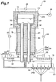
- FIG. 1 is a cross-sectional diagram showing a configuration of a glass-melting device for producing glass fibers according to a first embodiment.
- a glass-melting device 10 for producing glass fibers (hereinafter also referred to as "glass-melting device") includes a first glass-melting tank 12, a second glass-melting tank 14, a third glass-melting tank 16, an ascending conduit 18, a descending conduit 20, a decompression housing 22 and a bushing 24.
- the first glass-melting tank 12 heats molten glass and maintains the temperature of the molten glass, and an upper part of the first glass-melting tank 12 is opened.
- the first glass-melting tank 12 includes heating means for heating molten glass and maintaining the temperature of the molten glass.
- the heating means includes a pair of electrode parts 26 connected to opposing side surfaces of the first glass-melting tank 12, and a power supply 28 that supplies current to the electrode parts 26.
- the heating means makes the tank heat itself by applying current to the tank from the electrode parts 26.
- at least inner walls of the tank are preferably formed of a material that generates heat upon current being applied thereto, for example, platinum or a platinum alloy.
- the heating means may be, e.g., a burner or an electric heater.
- the second glass-melting tank 14 is arranged below the first glass-melting tank 12. Glass raw materials such as glass powder, molten glass and a glass gob are put into the second glass-melting tank 14 to melt these glass raw materials in the second glass-melting tank 14. An upper portion of the second glass-melting tank 14 is opened and exposed to an atmospheric-pressure atmosphere.
- the second glass-melting tank 14 includes heating means for melting glass raw materials.
- the heating means includes an electric heater including a heating wire 30 arranged at an upper part of the second glass-melting tank 14, and a power supply 32 that supplies current to the heating wire 30.
- the heating means may be a burner, or one that applies current to the tank via electrodes connected to the second glass-melting tank 14 to make the tank heat itself.
- at least inner walls of the tank are preferably formed of a material that generates heat upon current being applied thereto, for example, platinum or a platinum alloy.
- the third glass-melting tank 16 which is arranged below the first glass-melting tank 12, heats molten glass and maintains the temperature of the molten glass. An upper part of the third glass-melting tank 16 is opened and exposed to an atmospheric-pressure atmosphere.
- the third glass-melting tank 16 includes heating means for heating molten glass.
- the heating means includes an electric heater including a heating wire 34 arranged at the upper part of the third glass-melting tank 16, and a power supply 36 that supplies current to the heating wire 34.
- the heating means may be a burner, or one that makes the tank heat itself by applying current to the tank via electrodes connected to the third glass-melting tank 16.
- at least inner walls of the tank are preferably formed of a material that generates heat upon current being applied thereto, for example, platinum or an platinum alloy.
- each of the second glass-melting tank 14 and the third glass-melting tank 16 is formed to have a size such that the area resulting from adding up the liquid surface of the molten glass in the second glass-melting tank 14 and the liquid surface of the molten glass in the second glass-melting tank 14 is ten times or more the area of the liquid surface of the molten glass in the first glass-melting tank 12.
- the ascending conduit 18 sends up molten glass resulting from melting in the second glass-melting tank 14 to deliver the molten glass to the first glass-melting tank 12, and is formed in an elongated cylindrical shape extending downward from the first glass-melting tank 12 to the second glass-melting tank 14.
- the ascending conduit 18 includes heating means for heating the molten glass.
- the heating means includes a pair of flanged electrode parts 38 provided on an upper wall surface and a lower wall surface of the ascending conduit 18, and a power supply 40 that supplies current to the electrode parts 38.
- the heating means makes the ascending conduit 18 heat itself by applying current to the ascending conduit 18 via the electrode parts 38.
- the ascending conduit 18 includes a material that generates heat upon current being applied thereto, for example, platinum or a platinum alloy.
- the electrode part 38 may be provided on a wall surface of the first glass-melting tank 12 instead of the upper wall surface of the ascending conduit 18. In this case, it is preferable that the electrode part 38 be provided on a bottom part, or a lower part of a side part, of the first glass-melting tank 12 so as not to be an obstacle to the heating means of the first glass-melting tank 12.
- the descending conduit 20 sends the molten glass down from the first glass-melting tank 12 to deliver the molten glass to the third glass-melting tank 16, and is formed in an elongated cylindrical shape extending downward from the first glass-melting tank 12 to the third glass-melting tank 16.
- the descending conduit 20 includes heating means for heating the molten glass.
- the heating means includes a pair of flanged electrode parts 42 provided on an upper wall surface and a lower wall surface of the descending conduit 20, and a power supply 44 that supplies current to the electrode parts 42.
- the heating means makes the descending conduit 20 heats itself by applying current to the descending conduit 20 via the electrode part 42.
- the descending conduit 20 is formed of a material that generates heat upon current being applied thereto, for example, platinum or a platinum alloy.
- the electrode part 42 may be provided on a wall surface of the first glass-melting tank 12 instead of the upper wall surface of the descending conduit 20. In this case, it is preferable that the electrode part 42 be provided on a bottom part, or a lower part of a side part, of the first glass-melting tank 12 so as not to be an obstacle to the heating means of the first glass-melting tank 12.
- the decompression housing 22 exposes the first glass-melting tank 12, the ascending conduit 18 and the descending conduit 20 to a reduced-pressure atmosphere, and integrally covering the first glass-melting tank 12, the ascending conduit 18 and the descending conduit 20 in an airtight manner in a state in which lower ends of the ascending conduit 18 and the descending conduit 20 project therefrom.
- a material and structure of the decompression housing 22 are not specifically limited as long as the material and structure have airtightness and strength, and the decompression housing 22 is preferably formed of a metal material such as stainless steel.
- a heat insulating material 46 for heat-insulating efficiency enhancement is accommodated in a space among the decompression housing 22, the first glass-melting tank 12, the ascending conduit 18 and the descending conduit 20.
- the heat insulating material 46 provides heat insulation among the decompression housing 22, the first glass-melting tank 12, the ascending conduit 18 and the descending conduit 20, and lowers the temperature of the decompression housing 22 to a temperature equal to or lower than a heatproof temperature.
- the heat insulating material 46 is preferably formed of a material that lowers the temperature of the decompression housing 22 to the temperature equal to or lower than the heatproof temperature and retains the structure for a long time, preferably, insulating firebricks, which are excellent in shape retention property and economic efficiency, or an elastic heat insulating material having an elastic structure, for example.
- the decompression housing 22 is provided with a non-illustrated expansion/contraction mechanism that absorbs the contraction/expansion difference between the ascending conduit 18 and the descending conduit 20, and the decompression housing 22.
- a suction opening 22a for pressure reduction which is connected to a sucking device 48, is provided at a side wall of the decompression housing 22.
- the sucking device 48 sucks a gas inside the decompression housing 22 by means of a vacuum pump to provide an reduced-pressure atmosphere inside the decompression housing 22.
- the decompression housing 22 is connected to the ascending conduit 18 and the descending conduit 20 at lower end parts of the ascending conduit 18 and the descending conduit 20.
- Each of the connection parts has an airtight structure ensuring airtightness between the ascending conduit 18 and the descending conduit 20, and the decompression housing 22, and includes a non-illustrated sealing member such as an O-ring or packing provided between them. The details are provided later.
- the bushing 24 is provided at a bottom part of the third glass-melting tank 16.
- the bushing 24 includes a number of (for example, around 100 to 4000) nozzle 24a for spinning.
- the bushing 24 includes heating means for heating the molten glass.
- the heating means includes non-illustrated electrode parts provided on the bushing 24, and a power supply 50 that supplies current to the electrode parts.
- the heating means makes the bushing 24 heat itself by applying current to the bushing 24 via the electrode parts. Accordingly, the bushing 24 is formed of a material that generates heat upon current being applied thereto, for example, platinum or a platinum alloy.
- Figure 2 provides diagrams showing a manner of connection between the conduits and the decompression housing at the lower parts of the conduits:
- Figure 2(a) is a partially-fractured front view; and
- Figure 2(b) is a cross-sectional diagram along line b-b in Figure 2(a) .
- the flange 58 includes an upper flange 58a and a lower flange 58b integrally provided at the lower portions of the ascending conduit 18 and the descending conduit 20 and sandwiching the electrode part 38 and the electrode part 42, which are each provided in a flanged shape, therebetween.
- the electrode part 38 and the electrode part 42 are integrated, the electrode part 38 and the electrode part 42 may be electrically separated by, e.g., interposing an insulator therebetween.
- the upper flange 58a is connected to a lower end of the decompression housing 22 via, e.g., bolts, is placed on the upper side of the electrode part 38 and the electrode part 42.
- the lower flange 58b is inserted from the lower ends of the ascending conduit 18 and the descending conduit 20, and placed on the lower side of the electrode part 38 and the electrode part 42.
- Each of the upper flange 58a and the lower flange 58b is a ring-shaped member formed of, for example, a metal such as stainless steel, and includes a heat insulating material 46 inside.
- the upper flange 58a and the lower flange 58b sandwich the electrode part 38 and the electrode part 42 on the upper and lower sides, and these components are integrally connected via, e.g., bolts.
- Packing 80 for ensuring airtightness and electrical insulation is provided between the upper flange 58a and the electrode parts 38 and the electrode parts 42, and between the lower flange 58b and the electrode parts 38 and 42, respectively.
- an O-ring 90 for ensuring airtightness is provided between the decompression housing 22 and the upper flange 58a.
- the airtightness is retained between the lower parts of the ascending conduit 18 and the descending conduit 20 and the decompression housing 22 by the electrode part 38 and electrode part 42 sandwiched by the upper flange 58a and the lower flange 58b in an airtight manner.
- each of the upper flange 58a and the lower flange 58b is provided with the water-cooled tube 74.
- the water-cooled tube 74 is formed by hollowing out a flesh part of each of the upper flange 58a and the lower flange 58b.
- each water-cooled tube 74 desirably has a circular cross sectional shape, but may have a rectangular cross-sectional shape in consideration of workability.
- the water-cooled tubes 74 are desirably arranged in a circle. Furthermore, the water-cooled tubes 74 are provided immediately above and below the packing 80, enabling efficient cooling.
- each of the first glass-melting tank 12, the second glass-melting tank 14, the third glass-melting tank 16, the ascending conduit 18 and the descending conduit 20 is formed of platinum or a platinum alloy.
- the above description has been provided so as to indicate that the first glass-melting tank 12, the second glass-melting tank 14, the third glass-melting tank 16, the ascending conduit 18 and the descending conduit 20 are formed of platinum or a platinum alloy from the perspective of current application for heating, from the perspective of prevention of foreign substance contamination, at least such inner surfaces are formed of platinum or a platinum alloy, enabling minimization of foreign substance contamination due to deterioration in the interface between the respective component and molten glass, which may occur when forming such component using insulating firebricks.
- a glass fiber production startup process for preparing the production of a glass fiber is performed prior to a glass fiber production process for producing glass fibers.
- glass raw materials such as glass powder, molten glass and glass gob are put into the first glass-melting tank 12, the second glass-melting tank 14 and the third glass-melting tank 16.
- the glass powder includes a powder mixture of, e.g., clay, limestone, dolomite, colemanite, silica sand, alumina, calcium carbonate and/or sodium carbonate.
- the molten glass is one resulting from such mixture being melted in advance before being put into the tanks.
- the glass gob is one resulting from the molten glass being temporarily cooled and solidified.
- the first glass-melting tank 12, the second glass-melting tank 14 and the third glass-melting tank 16 are heated so that the glass raw materials put therein are melted.
- the ascending conduit 18 and the descending conduit 20 are also heated.
- the glass raw materials put in the first glass-melting tank 12, the second glass-melting tank 14 and the third glass-melting tank 16 are melted to occlude the lower end parts of the ascending conduit 18 and the descending conduit 20 with the molten glass.
- the pressure inside the decompression housing 22 is reduced by the sucking device 48 so that the air pressure inside the decompression housing 22 becomes lower than an atmospheric pressure by 0.4 to 0.9 atmospheres. Consequently, the pressure reduction in the decompression housing 22 raises the liquid surfaces of the molten glass inside the ascending conduit 18 and the descending conduit 20, and the insides of the ascending conduit 18 and the descending conduit 20 are thereby filled with the molten glass.
- first glass-melting tank 12, the second glass-melting tank 14, the third glass-melting tank 16, the ascending conduit 18, the descending conduit 20 and the bushing 24 are separately heated to adjust the respective regions to have respective specified temperatures.
- the respective temperatures are properly set in the range of, for example, 1200 to 1500°C for the second glass-melting tank 14, the ascending conduit 18, the first glass-melting tank 12, the descending conduit 20, the third glass-melting tank 16 and the bushing 24.
- the gas inside the decompression housing 22 is sucked by the sucking device 48 to adjust the inside of the decompression housing 22 so as to have a predetermined reduced-pressure atmosphere.
- the air pressure inside the decompression housing 22 is reduced so as to be lower than an atmospheric pressure by 0.4 to 0.9 atmospheres.
- the molten glass is drawn out from the nozzles 24a of the bushing 24, introduced into the first glass-melting tank 12 from the second glass-melting tank 14 through the ascending conduit 18, and further introduced from the first glass-melting tank 12 into the third glass-melting tank 16 through the descending conduit 20.
- the molten glass may simply be discharged from the nozzles 24a without drawing the molten glass out of the nozzles 24a of the bushing 24.
- the glass fiber production startup process is finished and the glass fiber production process is started.
- an amount of glass raw materials that corresponds to the amount of molten glass spun via the bushing 24 is put into the second glass-melting tank 14 so that the levels of the liquid surfaces of the molten glass in the first glass-melting tank 12, the second glass-melting tank 14 and the third glass-melting tank 16 are substantially constant. Then, the second glass-melting tank 14 is heated so that the temperature of the resulting molten glass becomes 1350 to 1550°C, thereby melting the glass raw materials.
- the decompression housing 22 is made to enter a pressure-reduced state by the sucking device 48 so that the air pressure inside the decompression housing 22 becomes lower than an atmospheric pressure by 0.4 to 0.9 atmospheres.
- first glass-melting tank 12, the second glass-melting tank 14, the third glass-melting tank 16, the ascending conduit 18, the descending conduit 20 and the bushing 24 are separately heated. Their respective temperatures are properly set in the range of, for example, 1350 to 1550°C for the second glass-melting tank 14, 1300 to 1500°C for the ascending conduit 18, 1300 to 1500°C for the first glass-melting tank 12, 1250 to 1450°C for the descending conduit 20, 1250 to 1450°C for the third glass-melting tank 16 and 1200 to 1400°C for the bushing 24.
- the glass raw materials be melted, and clarified to a certain degree in the second glass-melting tank 14.
- the temperature of the molten glass in the third glass-melting tank 16 be controlled so as to be lower than the temperature of the molten glass in each of the first glass-melting tank 12 and the second glass-melting tank 14. Consequently, generation of bubbles by reboiling can be suppressed.
- molten glass is introduced into the first glass-melting tank 12 from the second glass-melting tank 14 through the ascending conduit 18, and the molten glass is exposed to a reduced-pressure atmosphere in the first glass-melting tank 12 to defoam the molten glass.
- the molten glass is introduced into the third glass-melting tank 16 from the first glass-melting tank 12 through the descending conduit 20.
- the molten glass is wound under high tension from the nozzles 24a of the bushing 24 by a non-illustrated winder to spin the molten glass into a fiber.
- the flow rate of ejection of the molten glass from a nozzle 24a is, for example, 0.05 to 5.0g/minute.
- the liquid surface of the molten glass in the first glass-melting tank 12 is made to be higher than that of each of the second glass-melting tank 14 and the third glass-melting tank 16 by 150 cm or more, more preferably, 230 to 460 cm and most preferably among them, 250 cm or more. Consequently, the air pressure in the first glass-melting tank 12 can be made to be lower than an atmospheric pressure by around 0.4 to 0.9 atmospheres. Then, under this degree of reduced-pressure atmosphere, the gas in the molten glass continuously diffuses in the existing bubbles, and the diameters of the bubbles thereby rapidly increase, enabling provision of a large defoaming effect.
- the amount of suction by the sucking device 48 is controlled so that the reduced-pressure atmosphere to which the first glass-melting tank 12 is exposed, that is, the pressure difference (air pressure difference) between the air pressure inside the decompression housing 22 and the atmospheric pressure becomes constant. Consequently, fluctuations in the liquid surface of the molten glass due to minute fluctuations in the atmospheric pressure can be suppressed.
- the amount of glass raw materials put into the second glass-melting tank 14 is controlled based on the level of the liquid surface of the molten glass in the third glass-melting tank 16 so that the level becomes constant.
- the area resulting from adding up the liquid surface of the molten glass in the second glass-melting tank 14 and the liquid surface of the molten glass in the third glass-melting tank 16 is made to be ten times or more the area of the liquid surface of the molten glass in the first glass-melting tank 12.
- the areas of the liquid surfaces of the molten glass in the respective glass-melting tanks are made to meet expression (1) below and any one of expressions (2) and (3) below.
- the glass-melting device 10 when the glass-melting device 10 according to the present embodiment is made to enter an operating state in which the ascending conduit 18 and the descending conduit 20 are filled with molten glass, molten glass melted in the second glass-melting tank 14 ascends in the ascending conduit 18 by the siphon principle to be introduced into the first glass-melting tank 12, and descends in the descending conduit 20 to be introduced into the third glass-melting tank 16, and spun into a glass fiber via the bushing 24.
- the levels of the liquid surfaces of the molten glass in the second glass-melting tank 14 and the third glass-melting tank 16 become the same, and thus, even if fluctuations in liquid level occur in the first glass-melting tank 12 due to, e.g., fluctuations in air pressure of the atmosphere in the first glass-melting tank 12, liquid level fluctuations in the third glass-melting tank 16 from which a glass fiber is spun via the bushing 24 can be suppressed. Consequently, generation of bubbles brought from the surface of contact between the wall surface of the third glass-melting tank 16 and the molten glass can be suppressed, enabling effective reduction of mixing of bubbles into the spun glass fiber.
- the glass raw materials can be introduced into the second glass-melting tank 14 exposed to an atmospheric-pressure atmosphere, enabling easy adjustment of the liquid level of the molten glass, which varies as a result of a glass fiber being spun via the bushing 24.
- the first glass-melting tank 12 can be made airtight, enabling suppression of air pressure fluctuations in the atmosphere in the first glass-melting tank 12. Consequently, fluctuations in liquid level of the third glass-melting tank 16 can further be suppressed.
- the second glass-melting tank 14 enabling reduction in size of the first glass-melting tank 12 exposed to a reduced-pressure atmosphere, and thus, even if liquid level fluctuations occur in the first glass-melting tank 12, liquid level fluctuations in the third glass-melting tank 16 can further be suppressed.
- the first glass-melting tank 12 be arranged near the bushing 24 from which the molten glass is spun, that is, the third glass-melting tank 16, and such arrangement can easily be made by reduction in size of the first glass-melting tank 12.
- the ascending conduit 18 and the descending conduit 20 In order to expose the first glass-melting tank 12 to a reduced-pressure atmosphere, it is necessary that the first glass-melting tank 12 have a predetermined level difference from the second glass-melting tank 14 and the third glass-melting tank 16, and thus, the ascending conduit 18 and the descending conduit 20 necessarily have a long length. Meanwhile, since an amount of glass spun per unit time is extremely small, and thus, a long time is required for molten glass to pass through the ascending conduit 18 and the descending conduit 20. Thus, the ascending conduit 18 and the descending conduit 20 are heated, and covered by the decompression housing 22, enabling the molten glass introduced into the ascending conduit 18 and the descending conduit 20 to be prevented from being solidified because of a temperature decrease. In addition, since the decompression housing 22 integrally covers the ascending conduit 18 and the descending conduit 20, the structure of the decompression housing 22 can be simplified, enabling effective heating and temperature maintenance of the ascending conduit 18 and the descending conduit 20.
- first glass-melting tank 12, the second glass-melting tank 14, the third glass-melting tank 16, the ascending conduit 18 and the descending conduit 20 are separately heated by the respective heating means, optimum temperature conditions can be provided for the respective regions, and thus, generation of bubbles from the molten glass due to reboiling can be suppressed.
- the pressure inside the decompression housing 22 is reduced, making buckling of the ascending conduit 18 and the descending conduit 20 due to the pressure decrease difficult to occur, and therefore, the thicknesses of the walls of the ascending conduit 18 and the descending conduit 20 can be reduced. Consequently, the cost can be reduced in particular, for example, when the ascending conduit 18 and the descending conduit 20 are manufactured from an expensive material such as platinum.
- a glass-melting device 110 for producing glass fibers according to a second embodiment has a configuration that is basically the same as that of the glass-melting device 10 for producing glass fibers according to the first embodiment.
- the glass-melting device 110 for producing glass fibers is different from the glass-melting device 10 for producing glass fibers according to the first embodiment only in that: an ascending conduit and a descending conduit are composed of one double tube; and partition plates are provided to a first glass-melting tank 12.
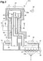
- Figure 3 is a cross-sectional diagram showing a configuration of a glass-melting device for producing glass fibers according to a second embodiment.
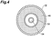
- Figure 4 is a cross-sectional diagram along line IV-IV in Figure 3 .
- Figure 5 is a transparent perspective diagram showing a first glass-melting tank in Figure 3 in detail.
- the glass-melting device 110 for producing glass fibers includes a first glass-melting tank 12, a second glass-melting tank 14, a third glass-melting tank 16, an ascending conduit part 52, a descending conduit part 54, a decompression housing 22 and a bushing 24.
- the ascending conduit part 52 sends up molten glass resulting from melting in the second glass-melting tank 14 to deliver the molten glass to the first glass-melting tank 12, and extends downward from the first glass-melting tank 12 to the second glass-melting tank 14.
- the descending conduit part 54 sends the molten glass down from the first glass-melting tank 12 to deliver the molten glass to the third glass-melting tank 16, and extends downward from the first glass-melting tank 12 to the third glass-melting tank 16. Furthermore, an upper end of the descending conduit part 54 penetrates the first glass-melting tank 12 and projects to a position higher than the liquid surface of molten glass in the first glass-melting tank 12.
- the ascending conduit part 52 and the descending conduit part 54 are included in a double-tube structure in which the ascending conduit part 52 is arranged on the outer side while the descending conduit part 54 being arranged on the inner side, and thereby integrally formed.
- the ascending conduit part 52 and the descending conduit part 54 are each formed in an elongated cylindrical shape.
- the ascending conduit part 52 and the descending conduit part 54 integrally extend downward from the first glass-melting tank 12 in the state of the double-tube structure, and at lower end parts of the ascending conduit part 52 and the descending conduit part 54, the descending conduit part 54 protrudes to the outside of the ascending conduit part 52, thereby the ascending conduit part 52 and the descending conduit part 54 being separated from each other.
- the ascending conduit part 52 includes an inflow communication hole 60, which is in communication with the first glass-melting tank 12, at an upper end part thereof, and the descending conduit part 54 includes an outflow communication hole 62, which is in communication with the first glass-melting tank 12, at the upper end part thereof.
- the molten glass that has ascended in the ascending conduit part 52 flows into the first glass-melting tank 12 via the inflow communication hole 60, and the molten glass introduced into the first glass-melting tank 12 flows out to the descending conduit part 54 via the outflow communication hole 62.
- the ascending conduit part 52 and the descending conduit part 54 include heating means for heating the molten glass.
- the heating means includes a pair of flanged electrode parts 56 provided on an upper wall surface and a lower wall surface of the ascending conduit part 52, and a power supply 40 that supplies current to the electrode parts 56.
- the heating means applies current to the ascending conduit part 52 via the electrode part 56 to make the ascending conduit part 52 heat itself.
- the descending conduit part 54 is heated indirectly by the molten glass heated by the self-heating of the ascending conduit part 52, and heats itself upon current being applied thereto via a joint part between the descending conduit part 54 and the ascending conduit part 52.
- the ascending conduit part 52 and the descending conduit part 54 each are formed of a material that generates heat upon current being applied thereto, for example, platinum or a platinum alloy.
- the electrode part 56 may be provided on a wall surface of the first glass-melting tank 12 instead of the upper wall surface of the ascending conduit part 52. In this case, it is preferable that the electrode part 56 be provided on a bottom part, or a lower part of a side part, of the first glass-melting tank 12 so as not to be an obstacle to the heating means of the first glass-melting tank 12.
- the first glass-melting tank 12 is provided with a partition plate 64 and an upper partition plate 66.
- the partition plate 64 and the upper partition plate 66 are each connected to the descending conduit part 54 projecting inside the first glass-melting tank 12 and respective wall surfaces of the first glass-melting tank 12, to divide the inside of the first glass-melting tank 12 into a region provided with the inflow communication hole 60 and a region provided with the outflow communication hole 62.
- the partition plate 64 is arranged at a position closer to the inflow communication hole 60 and the outflow communication hole 62 compared to the upper partition plate 66, and blocks transfer of molten glass.
- the partition plate 64 is provided so as to stand from a bottom surface of the first glass-melting tank 12 to a position higher than the liquid surface of the molten glass.
- the upper partition plate 66 is arranged at a position farther from the inflow communication hole 60 and the outflow communication hole 62 compared to the partition plate 64, and blocks molten glass from passing around the liquid surface and allows molten glass to pass around the bottom surface only.
- the upper partition plate 66 is provided so as to stand from the bottom surface of the first glass-melting tank 12 to a position higher than the liquid level of the molten glass, and a through hole 68 is formed in the vicinity of the bottom surface of the first glass-melting tank 12.
- Figure 6 includes diagrams showing a flow of molten glass in the first glass-melting tank.
- glass raw materials are put into the first glass-melting tank 12, the second glass-melting tank 14 and the third glass-melting tank 16. Then, the first glass-melting tank 12, the second glass-melting tank 14, the third glass-melting tank 16 and the ascending conduit part 52 are heated to melt glass raw material, and the lower end parts of the ascending conduit part 52 and the descending conduit part 54 are occluded by the melted glass, and then the pressure inside the decompression housing 22 is reduced by a sucking device 48 to raise the liquid surfaces of the molten glass in the ascending conduit part 52 and the descending conduit part 54, thereby the insides of the ascending conduit part 52 and the descending conduit part 54 being filled with the molten glass.
- first glass-melting tank 12, the second glass-melting tank 14, the third glass-melting tank 16, the ascending conduit part 52 and the bushing 24 are separately heated to adjust the respective regions to respective specified temperatures.
- the respective temperatures may properly be set as in the above-described first embodiment.
- a gas inside the decompression housing 22 is sucked by the sucking device 48 to adjust the inside of the decompression housing 22 to have a predetermined reduced-pressure atmosphere.
- the air pressure inside the decompression housing 22 is made to be lower than an atmospheric pressure by 0.4 to 0.9 atmospheres.
- the molten glass is drawn out from nozzles 24a of the bushing 24, introduced from the second glass-melting tank 14 into the first glass-melting tank 12 through the ascending conduit 18, and further introduced from the first glass-melting tank 12 into the third glass-melting tank 16 through the descending conduit 20.
- the molten glass may simply be discharged from the nozzles 24a of the bushing 24 without drawing the molten glass out of the nozzles 24a.
- the glass fiber production startup process is finished and a glass fiber production process is started.
- glass raw materials are put into the second glass-melting tank 14. Then, the second glass-melting tank 14 is heated so that the temperature of the resulting molten glass becomes 1350 to 1550°C, thereby melting the glass raw materials. Also, a gas inside the decompression housing 22 is sucked by the sucking device 48 to create a pressure-reduced state inside the decompression housing 22 so that the air pressure in the decompression housing 22 is lower than an atmospheric pressure by 0.4 to 0.9 atmospheres.
- first glass-melting tank 12, the second glass-melting tank 14, the third glass-melting tank 16, the ascending conduit part 52, the descending conduit part 54 and the bushing 24 are separately heated. Their respective temperatures are set as in the above-described first embodiment.
- molten glass is introduced from the second glass-melting tank 14 into the first glass-melting tank 12 through the ascending conduit part 52, and the molten glass is exposed to a reduced-pressure atmosphere in the first glass-melting tank 12 to defoam the molten glass.
- the molten glass flows into the first glass-melting tank 12 from the inflow communication hole 60, passes through the through hole 68 of the upper partition plate 66, which is far from the inflow communication hole 60, and then flows into the descending conduit part 54 from the outflow communication hole 62, which is far from the through hole 68.
- bubbles removed from the molten glass due to the exposure to the reduced-pressure atmosphere ascend toward the liquid surface, but are blocked from passing in the vicinity of the liquid surface of the molten glass by the upper partition plate 66.
- the molten glass is introduced from the first glass-melting tank 12 into the third glass-melting tank 16 through the descending conduit part 54, and the molten glass is wound under high tension from the nozzles 24a of the bushing 24 by a non-illustrated winder to spin the molten glass into a fiber.
- the ascending conduit part 52 and the descending conduit part 54 are included in a double-tube structure, and thus, when the ascending conduit part 52 is heated, the descending conduit part 54 is indirectly heated by, e.g., the heat radiated by the heating. Consequently, the ascending conduit part 52 and the descending conduit part 54 can efficiently be heated. In addition, there is almost no pressure difference between the inside and the outside of the descending conduit part 54, enabling reduction in thickness of the wall thereof.
- the partition plate 64 and the upper partition plate 66 being provided, the molten glass flowing in from the inflow communication hole 60 flows out from the outflow communication hole 62 through the through hole 68 formed in the upper partition plate 66.
- the upper partition plate 66 can prevent bubbles floating as a result of being removed from the molten glass from going with the flow of the molten glass, enabling the bubbles to be prevented from flowing into the descending conduit part 54. Consequently, mixing of bubbles into a spun glass fiber can more efficiently be reduced.
- a glass-melting device 210 for producing glass fibers according to a third embodiment has a configuration that is basically the same as that of the glass-melting device 110 for producing glass fibers according to the second embodiment.
- the glass-melting device 210 for producing glass fibers is different from the glass-melting device 110 for producing glass fibers according to the second embodiment only in a configuration of a housing covering a first glass-melting tank 12, an ascending conduit part 52 and a descending conduit part 54.
- Figure 7 is a cross-sectional diagram showing a configuration of a glass-melting device for producing glass fibers according to a third embodiment.
- the glass-melting device 210 for producing glass fibers includes a first glass-melting tank 12, a second glass-melting tank 14, a third glass-melting tank 16, an ascending conduit part 52, a descending conduit part 54, a decompression housing 70, a heat-insulating housing 72 and a bushing 24.
- the decompression housing 70 exposes the first glass-melting tank 12 to a reduced-pressure atmosphere, and covers the first glass-melting tank 12 in an airtight manner.
- a material and structure of the decompression housing 70 are not specifically limited as long as such material and structure have airtightness and strength, and the decompression housing 70 is preferably formed of a metal material such as stainless steel.
- a heat insulating material 46 for heat-insulation efficiency enhancement is accommodated in a space between the decompression housing 70 and the first glass-melting tank 12.
- a side wall of the decompression housing 70 is provided with a suction opening 70a for pressure reduction, which is connected to a sucking device 48.
- the heat-insulating housing 72 integrally covers the ascending conduit part 52 and the descending conduit part 54 in a state in which lower ends of the ascending conduit part 52 and the descending conduit part 54 project therefrom.
- a material and structure of the heat-insulating housing 72 are not specifically limited as long as such material and structure has strength, and the heat-insulating housing 72 is preferably formed of a metal material such stainless steel.
- a heat insulating material 46 for heat-insulation efficiency enhancement is accommodated in a space between the heat-insulating housing 72, and the ascending conduit part 52 and the descending conduit part 54.
- a support portion (not illustrated) supporting the heat insulating material 46 is attached to a lower end 72a of the heat-insulating housing 72, and no specific structure for providing airtightness between the ascending conduit part 52 and the descending conduit part 54 is provided. Furthermore, no sucking device is connected to the heat-insulating housing 72.
- the inside of the heat-insulating housing 72 has a normal pressure (atmospheric pressure).
- a method for producing glass fibers using the glass-melting device 210 for producing glass fibers is the same as that using the glass-melting device 110 for producing glass fibers according to the second embodiment.
- the ascending conduit part 52 and the descending conduit part 54 are integrally formed, enabling enhancement of the strength by properly setting the thicknesses of the walls of the ascending conduit part 52 and the descending conduit part 54, making buckling of the ascending conduit part 52 and the descending conduit part 54 difficult to occur. Consequently, there is no need to reduce the pressure inside the heat-insulating housing 72 covering the ascending conduit part 52 and the descending conduit part 54, enabling the inside of the heat-insulating housing 72 to have an atmospheric pressure, and thus, the need to provide strict sealing between the ascending conduit part 52 and the descending conduit part 54, and the heat-insulating housing 72 is eliminated.
- the glass-melting device 310 for producing glass fibers according to the fourth embodiment has a configuration that is basically the same as the glass-melting device 210 for producing glass fibers according to the third embodiment.
- the glass-melting device 310 for producing glass fibers is different from the glass-melting device 210 for producing glass fibers according to the third embodiment only in that an ascending conduit part and a descending conduit part included in a double-tube structure are replaced with each other in terms of the inner side and the outer side.
- an ascending conduit part and a descending conduit part included in a double-tube structure are replaced with each other in terms of the inner side and the outer side.
- Figure 8 is a cross-sectional diagram showing a configuration of a glass-melting device for producing glass fibers according to a fourth embodiment.
- the glass-melting device 310 for producing glass fibers includes a first glass-melting tank 12, a second glass-melting tank 14, a third glass-melting tank 16, an ascending conduit part 76, a descending conduit part 78, a decompression housing 70, a heat-insulating housing 72 and a bushing 24.
- the ascending conduit part 76 sends up molten glass resulting from melting in the second glass-melting tank 14 to deliver the molten glass to the first glass-melting tank 12, and extends downward from the first glass-melting tank 12 to the second glass-melting tank 14.
- An upper end of the ascending conduit part 76 penetrates the first glass-melting tank 12, and projects to a position higher than the liquid surface of the molten glass in the first glass-melting tank 12.
- the descending conduit part 78 sends the molten glass down from the first glass-melting tank 12 to deliver the molten glass to the third glass-melting tank 16, and extends downward from the first glass-melting tank 12 to the third glass-melting tank 16.
- the ascending conduit part 76 and the descending conduit part 78 are formed of a double-tube structure in which the ascending conduit part 76 is arranged on the inner side while the descending conduit part 78 is arranged on the outer side, and thereby integrally formed.
- the ascending conduit part 76 and the descending conduit part 78 are each formed in an elongated cylindrical shape.
- the ascending conduit part 76 and the descending conduit part 78 integrally extend downward from the first glass-melting tank 12 in the state of the double-tube structure, and at lower end parts of the ascending conduit part 76 and the descending conduit part 78, the ascending conduit part 76 protrudes to the outside of the descending conduit part 78, thereby the ascending conduit part 76 and the descending conduit part 78 being separated from each other.
- molten glass is introduced from the second glass-melting tank 14 into the first glass-melting tank 12 through the ascending conduit part 76, and the molten glass is defoamed in the first glass-melting tank 12. Subsequently, the molten glass is introduced from the first glass-melting tank 12 into the third glass-melting tank 16 through the descending conduit part 78, and the molten glass is wound under high tension by a non-illustrated winder from nozzles 24a of the bushing 24 to spin the molten glass into a fiber.
- the glass-melting device 410 for producing glass fibers according to the fifth embodiment has a configuration that is basically the same as the glass-melting device 210 for producing glass fibers according to the third embodiment.
- the glass-melting device 410 for producing glass fibers is different from the glass-melting device 210 for producing glass fibers according to the third embodiment only in that the ascending conduit part and the descending conduit part have a configuration that is different from that of the third embodiment. Therefore, only points of difference from the third embodiment will be described, and points that are the same as the third embodiment will be omitted.
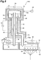
- Figure 9 is a cross-sectional diagram showing a configuration of a glass-melting device for producing glass fibers according to a fifth embodiment.
- Figure 10 is a cross-sectional diagram along line X-X in Figure 9 .
- a glass-melting device 410 for producing glass fibers includes a first glass-melting tank 12, a second glass-melting tank 14, a third glass-melting tank 16, an ascending conduit part 82, a descending conduit part 84, a decompression housing 70, a heat-insulating housing 72 and a bushing 24.
- the ascending conduit part 82 sends up molten glass resulting from melting in the second glass-melting tank 14 to deliver the molten glass to the first glass-melting tank 12, and is formed a semicylindrical shape extending downward from the first glass-melting tank 12 to the second glass-melting tank 14. Furthermore, an upper end of the ascending conduit part 82 penetrates the first glass-melting tank 12, and projects to a position higher than the liquid surface of the molten glass inside the first glass-melting tank 12.
- the descending conduit part 84 sends the molten glass down from the first glass-melting tank 12 to deliver the molten glass to the third glass-melting tank 16, and is formed in a semicylindrical shape extending downward from the first glass-melting tank 12 to the third glass-melting tank 16. Furthermore, an upper end of the descending conduit part 84 penetrates the first glass-melting tank 12, and projects to a position higher than the liquid surface of the molten glass inside the first glass-melting tank 12.
- the semicylindrical ascending conduit part 82 and the semicylindrical descending conduit part 84 are integrally joined to form one cylindrical conduit with a partition wall formed inside.
- the ascending conduit part 82 and the descending conduit part 84 are formed by a partition wall being formed inside one cylindrical conduit.
- the conduit including the ascending conduit part 82 and the descending conduit part 84 may be formed by joining semicylindrical conduits together, or providing a partition wall separating the ascending conduit part 82 and the descending conduit part 84 from each other inside a cylindrical conduit.
- the ascending conduit part 82 and the descending conduit part 84 integrally extend downward from the first glass-melting tank 12 in a joined state, and the ascending conduit part 82 and the descending conduit part 84 are separated from each other at lower end parts thereof.
- an inflow communication hole 94 that is in communication with the first glass-melting tank 12 is formed, and an upper end part of the descending conduit part 84, an outflow communication hole 96 that is in communication with the first glass-melting tank 12 is formed.
- the molten glass that has ascended in the ascending conduit part 82 flows into the first glass-melting tank 12 via the inflow communication hole 94, and the molten glass introduced into the first glass-melting tank 12 flows out to the descending conduit part 84 via the outflow communication hole 96.
- the ascending conduit part 82 and the descending conduit part 84 include heating means for heating the molten glass.
- the heating means includes a pair of flanged electrode parts 86 provided on an upper wall surface and a lower wall surface of the cylindrical conduit integrally including the ascending conduit part 82 and the descending conduit part 84, and a power supply 88 that supplies current to the electrode parts 86.
- the heating means applies current to the ascending conduit part 82 and the descending conduit part 84 via the electrode parts 86 to make the ascending conduit part 82 and the descending conduit part 84 heat themselves.
- the ascending conduit part 82 and the descending conduit part 84 each is formed of a material that generates heat upon current being applied thereto, for example, platinum or a platinum alloy.
- the electrode part 86 may be provided on a wall surface of the first glass-melting tank 12 instead of the upper wall surfaces of the ascending conduit part 82 and the descending conduit part 84. In this case, it is preferable that the electrode part 86 be provided on a bottom part, or a lower part of a side part, of the first glass-melting tank 12 so as not to be an obstacle to the heating means of the first glass-melting tank 12.
- separate electrodes may be provided to the ascending conduit part 82 and the descending conduit part 84 to separately apply current to the electrodes, thereby the ascending conduit part 82 and the descending conduit part 84 separately heat themselves.
- the first glass-melting tank 12, the second glass-melting tank 14, the third glass-melting tank 16, the ascending conduit part 82 and the descending conduit part 84 are heated, and the pressure inside the decompression housing 22 is reduced by a sucking device 48 to fill the insides of the ascending conduit part 82 and the descending conduit part 84 with molten glass.
- first glass-melting tank 12, the second glass-melting tank 14, the third glass-melting tank 16, the ascending conduit part 82, the descending conduit part 84 and the bushing 24 are separately heated to adjust the respective regions to specified temperatures.
- the respective temperatures may be set as in the first embodiment or the third embodiment.
- a gas inside the decompression housing 22 is sucked by the sucking device 48 to adjust the inside of the decompression housing 22 to a predetermined reduced-pressure atmosphere.
- the air pressure inside the decompression housing 22 is made to be lower than an atmospheric pressure by 0.4 to 0.9 atmospheres.
- molten glass resulting from melting in the second glass-melting tank 14 is made to ascend from the second glass-melting tank 14 through the ascending conduit part 82, introduced from the inflow communication hole 94 into the first glass-melting tank 12, and deformed in the first glass-melting tank 12. Subsequently, the molten glass is made to descend from the outflow communication hole 96 through the descending conduit part 84 to be introduced into the third glass-melting tank 16. Then, the molten glass is wound under high tension by a non-illustrated winder from nozzles 24a of the bushing 24 and spun into a fiber.
- the ascending conduit part 82 and the descending conduit part 84 are integrally joined to each other, and thus, when the ascending conduit part 82 and the descending conduit part 84 are heated, the ascending conduit part 82 and the descending conduit part 84 thermally expand in a substantially same behavior. Thus, a failure due to an expansion/contraction difference between the ascending conduit part 82 and the descending conduit part 84 can be prevented.
- a partition wall is formed inside one conduit to form the ascending conduit part 82 and the descending conduit part 84, enabling easy production of the ascending conduit part 82 and the descending conduit part 84.
- the conduit is reinforced by the partition wall inside the conduit, enabling reduction in thickness of the walls of the ascending conduit part 82 and the descending conduit part 84. In other words, where proper thicknesses of the walls of the ascending conduit part 82 and the descending conduit part 84 are set, occurrence of buckling of the conduit can be suppressed even under an atmospheric pressure without reducing the pressure inside the heat-insulating housing 72.
- the glass-melting device 510 for producing glass fibers according to a sixth embodiment has a configuration that is basically the same as that of the glass-melting device 10 for producing glass fibers according to the first embodiment.
- the glass-melting device 510 for producing glass fibers is different from the glass-melting device 10 for producing glass fibers according to the first embodiment only in that partition plates are provided inside the first glass-melting tank 12. Thus, only points of difference from the first embodiment will be described, and points that are the same as the first embodiment will be omitted.
- Figure 11 is a cross-sectional diagram showing a configuration of a glass-melting device for producing glass fibers according to a sixth embodiment.
- Figure 12 includes diagrams showing a flow of molten glass inside the first glass-melting tank.
- the first glass-melting tank 12 in the glass-melting device 510 for producing glass fibers includes one partition plate 98a, two upper partition plates 98b and three lower partition plates 98c.
- the partition plate 98a blocks transfer of molten glass.
- the partition plate 98a is arranged between the ascending conduit 18 and the descending conduit 20.
- the partition plate 98a is provided so as to stand from a bottom surface of the first glass-melting tank 12 to a position higher than the liquid surface of the molten glass.
- the upper partition plates 98b each block passage of molten glass in the vicinity of the liquid surface, and allow passage of the molten glass in the vicinity of the bottom surface only.
- the respective upper partition plate 98b are connected to the partition plate 98a, and the ascending conduit 18 and the descending conduit 20 are arranged between the upper partition plate 98b and the respective partition plates 98a.
- Each upper partition plate 98b is provided so as to stand from the bottom surface of the first glass-melting tank 12 to a position higher than the liquid surface of the molten glass, and includes a through hole 98d in the vicinity of the bottom surface of the first glass-melting tank 12.
- the respective lower partition plates 98c each block passage in the vicinity of the bottom surface of the first glass-melting tank 12 and allow passage of molten glass in the vicinity of the liquid surface only.
- the respective lower partition plates 98c are arranged between the partition plate 98a and the pair of upper partition plates 98b, and the ascending conduit 18 and the descending conduit 20 are arranged between the respective lower partition plates 98c and the partition plate 98a.
- the ascending conduit 18 and the descending conduit 20 are separated by the partition plate 98a, and arranged between the partition plate 98a and a pair of lower partition plates 98c adjacent to the partition plate 98a.
- Each lower partition plate 98c is provided so as to stand from the bottom surface of the first glass-melting tank 12 to a position lower than the liquid surface of the molten glass.
- providing the upper partition plates 98b enables bubbles floating as a result of being removed from molten glass to be prevented from going with the flow of the molten glass, and thus, the bubbles can be prevented from flowing into the descending conduit 20.
- the molten glass does not flow into the descending conduit 20 unless the molten glass climbs over the lower partition plates 98c, and thus, in the first glass-melting tank 12, retention time sufficient for removing bubbles from the molten glass can be secured.
- the bubbles removed from the molten glass can be prevented from being carried by a fast flow at the bottom part of the first glass-melting tank 12 and flowing into the descending conduit 20.
- the first glass-melting tank 12 is also made to be small.
- the molten glass can effectively be deformed by properly setting the volumes of the respective glass-melting tanks or the temperatures of the molten glass in the respective glass-melting tanks, melting glass raw materials in the second glass-melting tank 14, and as necessary, providing the upper partition plates 98b and the lower partition plates 98c in the first glass-melting tank 12, and thus, the first glass-melting tank 12 can be downsized.
- the first glass-melting tank 12 can sufficiently be downsized by designing the device so that the area of the liquid surface of molten glass in the first glass-melting tank 12 relative to the flow rate of the molten glass has a relatively large value such as 20(m 2 ⁇ hour/ton) to 200(m 2 ⁇ hour/ton).
- a glass-melting device 610 for producing glass fibers according to the seventh embodiment has a configuration that is basically the same as that of the glass-melting device 10 for producing glass fibers according to the first embodiment. Thus, points of difference from the first embodiment will be described below, and a description of points that are the same as the first embodiment will be omitted.
- Figure 13 is a cross-sectional diagram showing a configuration of a glass-melting device for producing glass fibers according to a seventh embodiment.
- Figure 14 includes diagrams showing a manner of connection between conduits and a decompression housing at lower parts of the conduits:
- Figure 14(a) is a partially-fractured front view;
- Figure 14(b) is a cross-sectional diagram along line b-b of Figure 14(a) .
- the glass-melting device 610 for producing glass fibers includes a first glass-melting tank 12, a second glass-melting tank 14, a third glass-melting tank 16, an ascending conduit 618, a descending conduit 620, a decompression housing 22 and a bushing 24.
- the ascending conduit 618 sends up molten glass resulting from melting in the second glass-melting tank 14 to deliver the molten glass to the first glass-melting tank 12, and is formed in an elongated cylindrical shape extending downward from the first glass-melting tank 12 to the second glass-melting tank 14.
- the descending conduit 620 sends the molten glass down from the first glass-melting tank 12 to deliver the molten glass to the third glass-melting tank 16, and is formed in an elongated cylindrical shape extending downward from the first glass-melting tank 12 to the third glass-melting tank 16.
- a conduit branch part 622 branching from the ascending conduit 618 and the descending conduit 620 is formed.
- the conduit branch part 622 is bent in the vicinity of the lower end parts of the decompression housing 22 so as to cover the ascending conduit 618 and the descending conduit 620 from the lower end parts of the ascending conduit 618 and descending conduit 620.
- the conduit branch part 622 is spaced a predetermined distance from the ascending conduit 618 and the descending conduit 620 and is formed in a cylindrical shape extending upward in a vertical direction along the ascending conduit 618 and the descending conduit 620.
- the ascending conduit 618 and the conduit branch part 622 are included in a double tube.
- An edge of the conduit branch part 622 is connected to an electrode part 38(42) sandwiched by an upper flange 58a and a lower flange 58b between the ascending conduit 618 and the descending conduit 620, and water-cooled tubes 74.
- the electrode part 38(42), and the ascending conduit 618 and the descending conduit 620 are spaced from each other by a predetermined distance. Consequently, airtightness is maintained between the lower parts of the ascending conduit 618 and the descending conduit 620, and the decompression housing 22, by the electrode part 38(42) sandwiched by the conduit branch part 622, and the upper flange 58a and the lower flange 58b in an airtight manner.
- the conduit branch part 622 is formed of a material that generates heat upon current being applied thereto, for example, platinum or a platinum alloy.
- current is applied to the ascending conduit 618 and the descending conduit 620 from the electrode part 38(42) via the conduit branch part 622.
- a heat insulating material 46 accommodated between the decompression housing 22, and the ascending conduit 618 and the descending conduit 620 is also accommodated between the ascending conduit 618 and the descending conduit 620, and the conduit branch part 622.
- the heat insulating material 46 is arranged in a space formed between the electrode part 38(42), and the ascending conduit 618 and the descending conduit 620. Consequently, an effect of a cooling action by the water-cooled tubes 74 provided in the upper flange 58a and the lower flange 58b imposed on the ascending conduit 618 and the descending conduit 620 can be reduced.
- a housing 624 covering the conduit branch part 622 is connected to the lower flange 58b, and the heat insulating material 46 is also accommodated between the housing 624 and the conduit branch part 622. Consequently, the efficiency of heating the conduit branch part 622 can be enhanced.
- a region between the conduit branch part 622 and the housing 624 and a region between the conduit branch part 622 and the ascending conduit 618 and the descending conduit 620 are separated from each other by the conduit branch part 622, and thus, the region between the conduit branch part 622 and the housing 624 does not have a reduced-pressure atmosphere even if suction is conducted by the sucking device 48.
- Figure 15 illustrates a temperature distribution of the ascending conduit and the descending conduit each sandwiched by a pair of electrode parts.
- the ascending conduit 618 and the descending conduit 620 are illustrated in a state in which the ascending conduit 618 and the descending conduit 620 are linearly extended.
- the temperature of central parts of the ascending conduit 618 and the descending conduit 620 upon being heated as a result of current being applied from the pair of electrode parts 38(42), the temperature of central parts of the ascending conduit 618 and the descending conduit 620, at which the temperature gradient is small, is raised to a set temperature, while the temperature of parts of the ascending conduit 618 and the descending conduit 620 around the parts of connection with the electrode parts 38(42) become lower toward end parts thereof because of the large temperature gradient.
- the electrode part 38(42) is connected to the edge of the conduit branch part 622 branching from the lower end parts of the ascending conduit 618 and the descending conduit 620, enabling providing a predetermined distance between the part of connection with the electrode part 38(42), and the ascending conduit 618 and the descending conduit 620, and the temperature of the lower end parts of the ascending conduit 618 and the descending conduit 620 can be raised to the stable set temperature. Consequently, the temperature of the molten glass introduced into the ascending conduit 618 and the descending conduit 620 can properly be raised.
- conduit parts according to the fourth embodiment or the fifth embodiment can be provided while the heat-insulating housing according to the second embodiment being employed.
- the partition plates in the first glass-melting tank according to the sixth embodiment can be provided while the conduits according to the second to fifth embodiments being provided.
- the structure of the conduit branch part according to the seventh embodiment can be provided to the conduits according to the second to sixth embodiments.
- sucking device for reducing the pressure in the first glass-melting tank
- sucking device for reducing the pressures in the conduits may be separately provided.
- the seventh embodiment has been described in terms of a case where the conduit branch part is formed in such a manner that the conduit branch part branches from both of the ascending conduit and the descending conduit, the conduit branch part may be formed so as to branch from only any one of the upper conduit and descending conduit.
- the present invention can be employed for a glass-melting device for producing glass fibers, which melts glass raw materials to spin a glass fiber.
Description
- The present invention relates to a glass-melting device for producing glass fibers which melts glass raw materials for spinning glass fibers, and a method for producing glass fibers using the same.
- A direct melt process and a marble melt process have been used in the production of glass fibers as typical melting methods for forming a plurality of glass fibers by fiberizing a molten glass, gathering the glass fibers, and spinning them as glass fiber yarn. In the direct melt process, powders or particulate matters of various mineral matters are mixed as glass raw materials, injected into a melting furnace, and melted to produce a molten glass. On the other hand, in the marble melt process, glass gobs referred to as marbles prepared by solidifying a molten glass are remelted to produce a molten glass (for example, see
JP 2003-192373 A - For spinning glass fibers, glass raw materials of mineral matters are melted as described above. However, bubbles are unfavorably generated during melting. The generated bubbles may be bubbles caused when raw materials are injected into a melting furnace, bubbles of volatile components (carbonate, sulfate, oxide) contained in the raw materials, bubbles generated at an interface of a zirconia brick of the melting furnace, or bubbles generated by reaction with platinum in the melting furnace.
- Due to these bubbles, some bubbles may exist in glass fibers during subsequent spinning. When this happens, glass fiber yarn may be unfavorably cut during spinning or mechanical strength or electrical insulation of a molded article using spun glass fiber yarn as a reinforcement material may be reduced.
- Thus, the bubbles are reduced by adding clarifying agent to the glass raw materials or solid raw materials or attaching a valve to an outlet of the melting furnace as disclosed in
JP 2003-192373 A - Also, as in
JP 02-042777 A - Furthermore, as in
JP 02-221129 A JP 2000-302456 A - However, addition of a clarificant is unfavorable from the perspective of environmental problems and costs, and also, provision of valves at outlets of a melting furnace as in
JP 2003-192373 A - Furthermore, in glass fiber production, the weight of glass spun per unit time is small, and thus, the flow rate of the molten glass flowing in a conduit is around 50 to 5000 g/minute in general.
- Thus, in the method in which glass is melted in a preliminary melting tank and the molten glass is introduced into a melting tank under a reduced pressure as in
JP 02-042777 A - Meanwhile, in the method in which molten glass is guided into a melting tank under a reduced pressure via an ascending tube to perform defoaming in the melting tank under a reduced pressure and then is guided from the melting tank to another melting tank via a descending tube as in
JP 02-221129 A JP 2000-302456 A JP 02-221129 A JP 2000-302456 A - Therefore, an object of the present invention is to provide a glass-melting device for producing glass fibers, which is capable of effectively reducing mixing of bubbles into a spun glass fiber, and a method for producing glass fibers using the same.
-
JP 57-149839 A -
JP 03-033020 A -
WO 2006/095523 A1 discloses a platinum or a platinum alloy structure suitable as a conduit tube for molten glass. -
JP 2000-128549 A -
EP 0 989 099 A -
JP 2007-022862 A -
DE 102 00 232 C1 andDE 102 00 233 C1 disclose devices for refining glass melt comprising a low pressure refining chamber. - A glass-melting device for producing glass fibers according to the present invention includes: a first glass-melting tank that is exposed to a reduced-pressure atmosphere by a sucking device; a first conduit part and a second conduit part extending downward from the first glass-melting tank; a heat-insulating housing integrally covering the first conduit part and the second conduit part; a second glass-melting tank provided below the first conduit part and exposed to an atmospheric-pressure atmosphere; a third glass-melting tank provided below the second conduit part and exposed to an atmospheric-pressure atmosphere; a bushing provided at a bottom part of the third glass-melting tank, the bushing including a number of nozzles; and heating means for separately heating at least any one of the first conduit part and the second conduit part, the first glass-melting tank, the second glass-melting tank, the third glass-melting tank and the bushing. An area S 1 of a liquid surface of molten glass in the first glass-melting tank, an area S2 of a liquid surface of molten glass in the second glass-melting tank, an area S3 of a liquid surface of molten glass in the third glass-melting tank and a number N of bushings provided at the bottom part of the glass-melting tank are made to meet expressions (1), (2) and (3) below:


- When the glass-melting device for producing glass fibers according to the present invention is made to enter an operating state in which the first conduit part and the second conduit part are filled with molten glass, molten glass in the second glass-melting tank ascends in the first conduit part by the siphon principle and is introduced into the first glass-melting tank, and then descends in the second conduit part and is introduced into the third glass-melting tank and spun into a glass fiber via the bushing. Consequently, the levels of the liquid surfaces of the molten glass in the second glass-melting tank and the third glass-melting tank become the same, and thus, even if liquid level fluctuations occur in the first glass-melting tank due to, e.g., fluctuations in air pressure of an atmosphere in the first glass-melting tank, liquid level fluctuations in the third glass-melting tank from which a glass fiber is spun via the bushing can be suppressed. Consequently, generation of bubbles brought from a surface of contact between a wall surface of the third glass-melting tank and the molten glass can be suppressed, enabling effective reduction of mixing of bubbles into a spun glass fiber.
- Furthermore, a glass raw material can be put into the second glass-melting tank exposed to an atmospheric-pressure atmosphere, and thus, the liquid level of molten glass changing as a result of a glass fiber being spun via the bushing can easily be adjusted. In addition, the first glass-melting tank can be made airtight, and thus, fluctuations in air pressure of the atmosphere in the first glass-melting tank can be suppressed. Consequently, liquid level fluctuations in the third glass-melting tank can further be suppressed.
- Furthermore, a glass raw material is melt in the second glass-melting tank, enabling downsizing of the first glass-melting tank exposed to a reduced-pressure atmosphere, and thus, a liquid level fluctuation in the third glass-melting tank can further be suppressed even though liquid level fluctuations occur in the first glass-melting tank. In addition, in order to reduce bubbles in a glass fiber, it is preferable that the first glass-melting tank be arranged near a spinning device that spins molten glass, that is the third glass-melting tank, and such arrangement can easily be attained by downsizing the first glass-melting tank.
- In order to expose the first glass-melting tank to a reduced-pressure atmosphere, it is necessary that the first glass-melting tank have a predetermined difference in height from the second glass-melting tank and the third glass-melting tank, and thus, the first conduit part and the second conduit part are inevitably long. Meanwhile, the weight of glass spun per unit time is extremely small, requiring a long time for molten glass to pass through the first conduit part and the second conduit part. Accordingly, heating at least any one of the first conduit part and the second conduit part and covering the first conduit part and the second conduit part with the heat-insulating housing enables molten glass introduced in the first conduit part and the second conduit part to be prevented from being solidified due to a temperature decrease. In addition, as a result of integrally covering the first conduit part and the second conduit part with the heat-insulating housing, the structure of the heat-insulating housing can be simplified, enabling efficient heating and temperature maintenance of the first conduit part and the second conduit part.
- As described above, in the glass-melting device for producing glass fibers according to the present invention, the flow rate of molten glass in the first conduit part and the second conduit part is extremely small, and thus, the first conduit part and the second conduit part can have a small diameter, and in addition, the first glass-melting tank can be downsized. Consequently, in the present invention, the first conduit part and the second conduit part can be integrally covered by the heat-insulating housing.
- Furthermore, as a result of the heating means separately heating at least any one of the first conduit part and the second conduit part, the first glass-melting tank, the second glass-melting tank, the third glass-melting tank and the bushing, optimum temperature conditions can be provided for the respective regions, enabling suppression of generation of bubbles from molten glass due to reboiling.
- In this case, it is preferable that a pressure inside the heat-insulating housing be reduced by sucking means. Thus, as a result of reducing a pressure inside the heat-insulating housing, buckling of the first conduit part and the second conduit part due to pressure reduction in the first glass-melting tank become difficult to occur, enabling a decrease in wall thickness of the first conduit part and the second conduit part. Consequently, especially where the first conduit part and the second conduit part are manufactured by an expensive material such as platinum, for example, the cost can be reduced.
- Furthermore, the heating means may include an electrode part on each of an upper part and a lower part of at least any one of the first conduit part and the second conduit part, and apply current to the electrode parts, thereby heating the electrode parts. Thus, as a result of applying current to the electrode part provided at each of the upper part and the lower part of at least any one of the first conduit part and the second conduit part to heat the electrode part, at least any one of the first conduit part and the second conduit part can be heated in its entirety, and thus, heating and temperature maintenance of molten glass introduced in at least any one of the first conduit part and the second conduit part can properly be performed.
- Also, at a lower part of at least any one of the first conduit and the second conduit, a conduit branch part branching from the lower part and extending upward may be formed, and the heating means may include an electrode part on each of an upper part of at least any one of the first conduit part and the second conduit part or the first melting tank, and the conduit branch part, and apply current to the electrode parts, thereby heating the electrode parts. Thus, as a result of providing an electrode part at the conduit branch part branching from the lower part of the conduit, a predetermined distance can be provided between a part connected to the electrode part and the conduit, enabling a temperature of the lower end part of the conduit to be also raised to a stable set temperature. Consequently, the temperature of molten glass introduced in the conduit can properly be raised.
- Furthermore, it is preferable that the first conduit part and the second conduit part be at least partially integrally configured. As a result of integrally configuring the first conduit part and the second conduit part as stated above, the strengths of the first conduit part and the second conduit part can be enhanced, making buckling of the first conduit part and the second conduit part difficult to occur. Consequently, an atmospheric pressure can be provided inside the heat-insulating housing, eliminating the need to provide strict sealing between the first conduit part and the second conduit part, and the heat-insulating housing. Consequently, the need to provide a specific mechanism to absorb an expansion/contraction difference between the first conduit part and the second conduit part, and the heat-insulating housing due to thermal expansion is eliminated, enabling a part of connection between the first conduit part and the second conduit part, and the heat-insulating housing to have a simple configuration.
- Furthermore, the first conduit part and the second conduit part may be included in a double-tube structure, and at least any one of the first conduit part and the second conduit part may be arranged in an inner part of any other one of the first conduit part and the second conduit part. As a result of the first conduit part and the second conduit part being included in a double-tube structure as stated above, heating any one of the first conduit part and the second conduit part enables any other one of the first conduit part and the second conduit part to be indirectly heated by heat radiated by the heating. Consequently, the first conduit part and the second conduit part can efficiently be heated. In addition, there is almost no pressure difference between the inside and the outside of the inner-side conduit part, enabling a decrease in wall thickness of the inner-side conduit.
- In this case, it is preferable that: first conduit part be arranged on an outer side of the double-tube structure; and the second conduit part be arranged on an inner side of the double-tube structure. As a result of providing such configuration as stated above, heating only the first conduit part results in the second conduit part being indirectly heated by the heating of the first conduit part, and thus, the temperature of the second conduit part can easily be made to be lower than the temperature of the first conduit part. Consequently, generation of bubbles due to reboiling can be suppressed.
- Also, the first conduit part and the second conduit part may be integrally joined to each other. Since the first conduit part and the second conduit part are joined to each other as stated above, when the first conduit part and the second conduit part are heated, the first conduit part and the second conduit part thermally expand in a substantially same behavior. Thus, a failure caused due to an expansion/contraction difference between the first conduit part and the second conduit part due to thermal expansion can be prevented.
- In this case, it is preferable that the first conduit part and the second conduit part be formed inside one conduit by forming a partition wall inside the conduit. As a result of the first conduit part and the second conduit part being formed inside one conduit by forming a partition wall inside the conduit as stated above, the first conduit part and the second conduit part can easily be fabricated. In addition, the conduit is reinforced by the partition wall inside the conduit, enabling a decrease in wall thickness of the first conduit part and the second conduit part. In other words, properly setting the wall thicknesses of the first conduit part and the second conduit part enables suppression of occurrence of buckling of the conduit even though the inside of the heat-insulating housing has an atmospheric pressure without pressure reduction.
- Furthermore, it is preferable that the first glass-melting tank be provided with at least any one of an upper partition plate forming an opening at a bottom part of the first glass-melting tank and dividing an upper part of molten glass, and a lower partition plate including an opening in the vicinity of a liquid surface of molten glass and dividing the bottom part of the first glass-melting tank. As a result of providing the upper partition plate as stated above, bubbles floating as a result of being removed from molten glass can be prevented from going with the flow of the molten glass, enabling the bubbles to be prevented from flowing into the second conduit part. Meanwhile, as a result of providing the lower partition plate, the molten glass does not flow into the second conduit part unless the molten glass climbs over the lower partition plate, and thus, in the first glass-melting tank, retention time sufficient for removing bubbles from the molten glass can be secured. In addition, the bubbles removed from the molten glass can be prevented from being carried by a fast flow at the bottom part of the first glass-melting tank and flowing into the second conduit part. As a result, mixing of bubbles into a spun glass fiber can more effectively be reduced.
- A method for producing glass fibers according to the present invention includes a method for producing glass fibers using the above-stated glass-melting device for producing glass fibers, the method including: exposing the first glass-melting tank to a reduced-pressure atmosphere to introduce molten glass resulting from a glass raw material being melted in the second glass-melting tank to the first glass-melting tank via the first conduit part, and introducing the molten glass to the third glass-melting tank via the second conduit part; separately heating at least any one of the first conduit part and the second conduit part, the first glass-melting tank, the second glass-melting tank, the third glass-melting tank and the bushing; and spinning a glass fiber from the nozzles of the bushing.
- In the method for producing glass fibers according to the present invention, as a result of exposing the first glass-melting tank to a reduced-pressure atmosphere to introduce molten glass resulting from a glass raw material being melted in the second glass-melting tank to the first glass-melting tank via the first conduit part, and introducing the molten glass to the third glass-melting tank via the second conduit part, the molten glass is introduced from the second glass melting into the third glass-melting tank through the first glass-melting tank by the siphon principle, and a glass fiber is spun via the bushing. Consequently, liquid levels of the molten glass in the second glass-melting tank and the third glass-melting tank become the same, and thus, even though liquid level fluctuations occur in the first glass-melting tank due to, e.g., fluctuations in air pressure of an atmosphere in the first glass-melting tank, liquid level fluctuations in the third glass-melting tank from which a glass fiber is spun via the bushing can be suppressed. Consequently, generation of bubbles brought from the surface of contact between the wall surface of the third glass-melting tank and the molten glass can be suppressed, enabling effective reduction of mixing of bubbles into a spun glass fiber.
- Furthermore, as a result of separately heating at least any one of the first conduit part and the second conduit part, the first glass-melting tank, the second glass-melting tank, the third glass-melting tank and the bushing, optimum temperature conditions can be provided for the respective regions, enabling suppression of generation of bubbles from the molten glass due to reboiling.
- In this case, it is preferable that a liquid surface of the molten glass in the first glass-melting tank be made to be higher than a liquid surface of the molten glass in each of the second glass-melting tank and the third glass-melting tank by 250 cm or more. Consequently, an air pressure in the first glass-melting tank can be made to be lower than an atmospheric pressure by around 0.4 to 0.9 atmospheres or more. Under such degree of reduced-pressure atmosphere, a gas in the molten glass continuously diffuses inside the existing bubbles, resulting a sharp increase in the diameters of the bubbles, enabling provision of a large defoaming effect.
- A sum of the area of the liquid surface of the molten glass in the second glass-melting tank and the area of the liquid surface of the molten glass in the third glass-melting tank is made to be ten times or more the area of the liquid surface of the molten glass in the first glass-melting tank. Consequently, since the levels of the liquid surfaces of the molten glass in the second glass-melting tank and the levels of the liquid surfaces of the molten glass in the third glass-melting tank are the same, even though liquid level fluctuations occur in the first glass-melting tank due to, e.g., fluctuations in air pressure of an atmosphere in the first glass-melting tank, fluctuations in liquid level of the liquid surface of the molten glass in the third glass-melting tank can be made to small. Consequently, generation of bubbles brought from the surface of contact between the wall surface of the third glass-melting tank and the molten glass can be suppressed. Furthermore, fluctuations in thickness of a spun glass fiber can be suppressed, enabling suppression of variation in strength and/or electrical characteristics of molded products due to fluctuations in the count of the glass fiber.
- The present invention enables mixing of bubbles into a spun glass fiber to be effectively reduced.
-
- [
Figure 1] Figure 1 is a cross-sectional diagram showing a configuration of a glass-melting device for producing glass fibers according to a first embodiment. - [
Figure 2] Figure 2(a) and 2(b) include diagrams showing a manner of connection between conduits and a decompression housing at lower portions of the conduits:Figure 2(a) is a partially-fractured front view; andFigure 2(b) is a cross-sectional view along line b-b inFigure 2(a) . - [
Figure 3] Figure 3 is a cross-sectional diagram showing a configuration of glass-melting device for producing glass fibers according to a second embodiment. - [
Figure 4] Figure 4 is a cross-sectional diagram along line IV-IV indicated inFigure 3 . - [
Figure 5] Figure 5 is a transparent perspective diagram showing the first glass-melting tank inFigure 3 in detail. - [
Figure 6] Figure 6 includes diagrams showing a flow of molten glass in the first glass-melting tank. - [
Figure 7] Figure 7 is a cross-sectional diagram showing a configuration of a glass-melting device for producing glass fibers according to a third embodiment. - [
Figure 8] Figure 8 is a cross-sectional diagram showing a configuration of a glass-melting device for producing glass fibers according to a fourth embodiment. - [
Figure 9] Figure 9 is a cross-sectional diagram showing a configuration of a glass-melting device for producing glass fibers according to a fifth embodiment. - [
Figure 10] Figure 10 is a cross-sectional diagram along line X-X indicated inFigure 9 . - [
Figure 11] Figure 11 is a cross-sectional diagram showing a configuration of a glass-melting device for producing glass fibers according to a sixth embodiment. - [
Figure 12] Figure 12 includes diagrams showing a flow of molten glass inside a first glass-melting tank. - [
Figure 13] Figure 13 is a cross-sectional diagram showing a configuration of a glass-melting device for producing glass fibers according to a seventh embodiment. - [
Figure 14] Figure 14(a) and 14(b) include diagrams showing a manner of connection between conduits and a decompression housing at lower parts of the conduits:Figure 14(a) is a partially-fractured front view; andFigure 14(b) is a cross-sectional diagram along line b-b inFigure 14(a) . - [
Figure 15] Figure 15 showing a temperature distribution in an ascending conduit or a descending conduit interposed between a pair of electrode parts. - Hereinafter, preferred embodiments of a glass-melting device for producing glass fibers and a method for producing glass fibers using the same according to the present invention will be described in detail with reference to the drawings. Throughout the drawings, parts identical or corresponding to each other are provided with a same reference number, and a repetitive description thereof will be omitted.
-
Figure 1 is a cross-sectional diagram showing a configuration of a glass-melting device for producing glass fibers according to a first embodiment. As illustrated inFigure 1 , a glass-meltingdevice 10 for producing glass fibers (hereinafter also referred to as "glass-melting device") includes a first glass-melting tank 12, a second glass-melting tank 14, a third glass-melting tank 16, an ascendingconduit 18, a descendingconduit 20, adecompression housing 22 and abushing 24. - The first glass-
melting tank 12 heats molten glass and maintains the temperature of the molten glass, and an upper part of the first glass-melting tank 12 is opened. - The first glass-
melting tank 12 includes heating means for heating molten glass and maintaining the temperature of the molten glass. The heating means includes a pair ofelectrode parts 26 connected to opposing side surfaces of the first glass-melting tank 12, and apower supply 28 that supplies current to theelectrode parts 26. The heating means makes the tank heat itself by applying current to the tank from theelectrode parts 26. For self-heating, at least inner walls of the tank are preferably formed of a material that generates heat upon current being applied thereto, for example, platinum or a platinum alloy. The heating means may be, e.g., a burner or an electric heater. - The second glass-
melting tank 14 is arranged below the first glass-melting tank 12. Glass raw materials such as glass powder, molten glass and a glass gob are put into the second glass-melting tank 14 to melt these glass raw materials in the second glass-melting tank 14. An upper portion of the second glass-melting tank 14 is opened and exposed to an atmospheric-pressure atmosphere. - The second glass-
melting tank 14 includes heating means for melting glass raw materials. The heating means includes an electric heater including aheating wire 30 arranged at an upper part of the second glass-melting tank 14, and apower supply 32 that supplies current to theheating wire 30. The heating means may be a burner, or one that applies current to the tank via electrodes connected to the second glass-melting tank 14 to make the tank heat itself. For self-heating, at least inner walls of the tank are preferably formed of a material that generates heat upon current being applied thereto, for example, platinum or a platinum alloy. - The third glass-
melting tank 16, which is arranged below the first glass-melting tank 12, heats molten glass and maintains the temperature of the molten glass. An upper part of the third glass-melting tank 16 is opened and exposed to an atmospheric-pressure atmosphere. - The third glass-
melting tank 16 includes heating means for heating molten glass. The heating means includes an electric heater including aheating wire 34 arranged at the upper part of the third glass-melting tank 16, and apower supply 36 that supplies current to theheating wire 34. The heating means may be a burner, or one that makes the tank heat itself by applying current to the tank via electrodes connected to the third glass-melting tank 16. For self-heating, at least inner walls of the tank are preferably formed of a material that generates heat upon current being applied thereto, for example, platinum or an platinum alloy. - Preferably, each of the second glass-
melting tank 14 and the third glass-melting tank 16 is formed to have a size such that the area resulting from adding up the liquid surface of the molten glass in the second glass-melting tank 14 and the liquid surface of the molten glass in the second glass-melting tank 14 is ten times or more the area of the liquid surface of the molten glass in the first glass-melting tank 12. - The ascending
conduit 18 sends up molten glass resulting from melting in the second glass-melting tank 14 to deliver the molten glass to the first glass-melting tank 12, and is formed in an elongated cylindrical shape extending downward from the first glass-melting tank 12 to the second glass-melting tank 14. - The ascending
conduit 18 includes heating means for heating the molten glass. The heating means includes a pair offlanged electrode parts 38 provided on an upper wall surface and a lower wall surface of the ascendingconduit 18, and apower supply 40 that supplies current to theelectrode parts 38. The heating means makes the ascendingconduit 18 heat itself by applying current to the ascendingconduit 18 via theelectrode parts 38. Accordingly, the ascendingconduit 18 includes a material that generates heat upon current being applied thereto, for example, platinum or a platinum alloy. Theelectrode part 38 may be provided on a wall surface of the first glass-melting tank 12 instead of the upper wall surface of the ascendingconduit 18. In this case, it is preferable that theelectrode part 38 be provided on a bottom part, or a lower part of a side part, of the first glass-melting tank 12 so as not to be an obstacle to the heating means of the first glass-melting tank 12. - The descending
conduit 20 sends the molten glass down from the first glass-melting tank 12 to deliver the molten glass to the third glass-melting tank 16, and is formed in an elongated cylindrical shape extending downward from the first glass-melting tank 12 to the third glass-melting tank 16. - The descending
conduit 20 includes heating means for heating the molten glass. The heating means includes a pair offlanged electrode parts 42 provided on an upper wall surface and a lower wall surface of the descendingconduit 20, and apower supply 44 that supplies current to theelectrode parts 42. The heating means makes the descendingconduit 20 heats itself by applying current to the descendingconduit 20 via theelectrode part 42. Accordingly, the descendingconduit 20 is formed of a material that generates heat upon current being applied thereto, for example, platinum or a platinum alloy. Theelectrode part 42 may be provided on a wall surface of the first glass-melting tank 12 instead of the upper wall surface of the descendingconduit 20. In this case, it is preferable that theelectrode part 42 be provided on a bottom part, or a lower part of a side part, of the first glass-melting tank 12 so as not to be an obstacle to the heating means of the first glass-melting tank 12. - The
decompression housing 22 exposes the first glass-melting tank 12, the ascendingconduit 18 and the descendingconduit 20 to a reduced-pressure atmosphere, and integrally covering the first glass-melting tank 12, the ascendingconduit 18 and the descendingconduit 20 in an airtight manner in a state in which lower ends of the ascendingconduit 18 and the descendingconduit 20 project therefrom. A material and structure of thedecompression housing 22 are not specifically limited as long as the material and structure have airtightness and strength, and thedecompression housing 22 is preferably formed of a metal material such as stainless steel. - A
heat insulating material 46 for heat-insulating efficiency enhancement is accommodated in a space among thedecompression housing 22, the first glass-melting tank 12, the ascendingconduit 18 and the descendingconduit 20. Theheat insulating material 46 provides heat insulation among thedecompression housing 22, the first glass-melting tank 12, the ascendingconduit 18 and the descendingconduit 20, and lowers the temperature of thedecompression housing 22 to a temperature equal to or lower than a heatproof temperature. Accordingly, theheat insulating material 46 is preferably formed of a material that lowers the temperature of thedecompression housing 22 to the temperature equal to or lower than the heatproof temperature and retains the structure for a long time, preferably, insulating firebricks, which are excellent in shape retention property and economic efficiency, or an elastic heat insulating material having an elastic structure, for example. - Upon the ascending
conduit 18 and the descendingconduit 20 being heated, the ascendingconduit 18 and the descendingconduit 20, and thedecompression housing 22 expand/contract due to thermal expansion. However, a contraction/expansion difference occurs between the ascendingconduit 18 and the descendingconduit 20, and thedecompression housing 22 because of the difference in thermal expansion between them. Therefore, thedecompression housing 22 is provided with a non-illustrated expansion/contraction mechanism that absorbs the contraction/expansion difference between the ascendingconduit 18 and the descendingconduit 20, and thedecompression housing 22. - A
suction opening 22a for pressure reduction, which is connected to a suckingdevice 48, is provided at a side wall of thedecompression housing 22. - The sucking
device 48 sucks a gas inside thedecompression housing 22 by means of a vacuum pump to provide an reduced-pressure atmosphere inside thedecompression housing 22. - The
decompression housing 22 is connected to the ascendingconduit 18 and the descendingconduit 20 at lower end parts of the ascendingconduit 18 and the descendingconduit 20. Each of the connection parts has an airtight structure ensuring airtightness between the ascendingconduit 18 and the descendingconduit 20, and thedecompression housing 22, and includes a non-illustrated sealing member such as an O-ring or packing provided between them. The details are provided later. - The
bushing 24 is provided at a bottom part of the third glass-melting tank 16. Thebushing 24 includes a number of (for example, around 100 to 4000)nozzle 24a for spinning. - The
bushing 24 includes heating means for heating the molten glass. The heating means includes non-illustrated electrode parts provided on thebushing 24, and apower supply 50 that supplies current to the electrode parts. The heating means makes thebushing 24 heat itself by applying current to thebushing 24 via the electrode parts. Accordingly, thebushing 24 is formed of a material that generates heat upon current being applied thereto, for example, platinum or a platinum alloy. - The above-described respective heating means in the first glass-
melting tank 12, the second glass-melting tank 14, the third glass-melting tank 16, the ascendingconduit 18, the descendingconduit 20 and thebushing 24 allow separate thermal adjustments. - Here, as described above, since the
decompression housing 22 covers the ascendingconduit 18 and the descendingconduit 20 as well, connection between the lower parts of the ascendingconduit 18 and the descendingconduit 20, and thedecompression housing 22 is important. Therefore, in the present embodiment, as illustrated inFigure 2 , the lower parts of the ascendingconduit 18 and the descendingconduit 20 and thedecompression housing 22 are connected via aflange 58 including water-cooledtubes 74.Figure 2 provides diagrams showing a manner of connection between the conduits and the decompression housing at the lower parts of the conduits:Figure 2(a) is a partially-fractured front view; andFigure 2(b) is a cross-sectional diagram along line b-b inFigure 2(a) . - More specifically, the
flange 58 includes anupper flange 58a and alower flange 58b integrally provided at the lower portions of the ascendingconduit 18 and the descendingconduit 20 and sandwiching theelectrode part 38 and theelectrode part 42, which are each provided in a flanged shape, therebetween. Although theelectrode part 38 and theelectrode part 42 are integrated, theelectrode part 38 and theelectrode part 42 may be electrically separated by, e.g., interposing an insulator therebetween. Theupper flange 58a is connected to a lower end of thedecompression housing 22 via, e.g., bolts, is placed on the upper side of theelectrode part 38 and theelectrode part 42. Thelower flange 58b is inserted from the lower ends of the ascendingconduit 18 and the descendingconduit 20, and placed on the lower side of theelectrode part 38 and theelectrode part 42. Each of theupper flange 58a and thelower flange 58b is a ring-shaped member formed of, for example, a metal such as stainless steel, and includes aheat insulating material 46 inside. - As described above, the
upper flange 58a and thelower flange 58b sandwich theelectrode part 38 and theelectrode part 42 on the upper and lower sides, and these components are integrally connected via, e.g., bolts.Packing 80 for ensuring airtightness and electrical insulation is provided between theupper flange 58a and theelectrode parts 38 and theelectrode parts 42, and between thelower flange 58b and theelectrode parts ring 90 for ensuring airtightness is provided between thedecompression housing 22 and theupper flange 58a. As described above, the airtightness is retained between the lower parts of the ascendingconduit 18 and the descendingconduit 20 and thedecompression housing 22 by theelectrode part 38 andelectrode part 42 sandwiched by theupper flange 58a and thelower flange 58b in an airtight manner. - Here, the
electrode part 38 and theelectrode part 42 are heated by direct current application, and thus, theelectrode part 38 and theelectrode part 42 themselves have a high temperature. Accordingly, the temperature of the connection part becomes 300°C or higher, which is equal to or exceeds the heatproof temperatures of the O-ring 90 and the packing 80, and may result in impossibility to retain the airtightness. Therefore, as illustrated inFigure 2 , each of theupper flange 58a and thelower flange 58b is provided with the water-cooledtube 74. In the present embodiment, the water-cooledtube 74 is formed by hollowing out a flesh part of each of theupper flange 58a and thelower flange 58b. - However, water-cooling cools the ascending
conduit 18 and the descendingconduit 20, which leads to a decrease in temperature of molten glass flowing in the ascendingconduit 18 and the descendingconduit 20, and thus, the water-cooledtubes 74 should be positioned as far away from the ascendingconduit 18 and the descendingconduit 20 as possible. However, positioning the water-cooledtubes 74 far away from the ascendingconduit 18 and the descendingconduit 20 results in an increase in size of thedecompression housing 22, and thus, the design should be made so that the distances from the ascendingconduit 18 and the descendingconduit 20 are around 90 to 200 mm. Furthermore, each water-cooledtube 74 desirably has a circular cross sectional shape, but may have a rectangular cross-sectional shape in consideration of workability. - Furthermore, in order to uniformly cool the O-
ring 90 and the packing 80, the water-cooledtubes 74 are desirably arranged in a circle. Furthermore, the water-cooledtubes 74 are provided immediately above and below the packing 80, enabling efficient cooling. - Preferably, at least an inner surface of each of the first glass-
melting tank 12, the second glass-melting tank 14, the third glass-melting tank 16, the ascendingconduit 18 and the descendingconduit 20 is formed of platinum or a platinum alloy. Although the above description has been provided so as to indicate that the first glass-melting tank 12, the second glass-melting tank 14, the third glass-melting tank 16, the ascendingconduit 18 and the descendingconduit 20 are formed of platinum or a platinum alloy from the perspective of current application for heating, from the perspective of prevention of foreign substance contamination, at least such inner surfaces are formed of platinum or a platinum alloy, enabling minimization of foreign substance contamination due to deterioration in the interface between the respective component and molten glass, which may occur when forming such component using insulating firebricks. - Next, a method for producing glass fibers using the above-described glass-melting
device 10 will be described. - First, for starting operation of the glass-melting
device 10, a glass fiber production startup process for preparing the production of a glass fiber is performed prior to a glass fiber production process for producing glass fibers. - In the glass fiber production startup process, first, glass raw materials such as glass powder, molten glass and glass gob are put into the first glass-
melting tank 12, the second glass-melting tank 14 and the third glass-melting tank 16. The glass powder includes a powder mixture of, e.g., clay, limestone, dolomite, colemanite, silica sand, alumina, calcium carbonate and/or sodium carbonate. The molten glass is one resulting from such mixture being melted in advance before being put into the tanks. The glass gob is one resulting from the molten glass being temporarily cooled and solidified. - Next, the first glass-
melting tank 12, the second glass-melting tank 14 and the third glass-melting tank 16 are heated so that the glass raw materials put therein are melted. Here, the ascendingconduit 18 and the descendingconduit 20 are also heated. Then, the glass raw materials put in the first glass-melting tank 12, the second glass-melting tank 14 and the third glass-melting tank 16 are melted to occlude the lower end parts of the ascendingconduit 18 and the descendingconduit 20 with the molten glass. Subsequently, the pressure inside thedecompression housing 22 is reduced by the suckingdevice 48 so that the air pressure inside thedecompression housing 22 becomes lower than an atmospheric pressure by 0.4 to 0.9 atmospheres. Consequently, the pressure reduction in thedecompression housing 22 raises the liquid surfaces of the molten glass inside the ascendingconduit 18 and the descendingconduit 20, and the insides of the ascendingconduit 18 and the descendingconduit 20 are thereby filled with the molten glass. - Furthermore, the first glass-
melting tank 12, the second glass-melting tank 14, the third glass-melting tank 16, the ascendingconduit 18, the descendingconduit 20 and thebushing 24 are separately heated to adjust the respective regions to have respective specified temperatures. The respective temperatures are properly set in the range of, for example, 1200 to 1500°C for the second glass-melting tank 14, the ascendingconduit 18, the first glass-melting tank 12, the descendingconduit 20, the third glass-melting tank 16 and thebushing 24. - Furthermore, the gas inside the
decompression housing 22 is sucked by the suckingdevice 48 to adjust the inside of thedecompression housing 22 so as to have a predetermined reduced-pressure atmosphere. The air pressure inside thedecompression housing 22 is reduced so as to be lower than an atmospheric pressure by 0.4 to 0.9 atmospheres. - Then, the molten glass is drawn out from the
nozzles 24a of thebushing 24, introduced into the first glass-melting tank 12 from the second glass-melting tank 14 through the ascendingconduit 18, and further introduced from the first glass-melting tank 12 into the third glass-melting tank 16 through the descendingconduit 20. In the glass fiber production startup process, the molten glass may simply be discharged from thenozzles 24a without drawing the molten glass out of thenozzles 24a of thebushing 24. - Then, upon the glass-melting
device 10 reaching the specified temperatures and air pressures, the glass fiber production startup process is finished and the glass fiber production process is started. - In the glass fiber production process, an amount of glass raw materials that corresponds to the amount of molten glass spun via the
bushing 24 is put into the second glass-melting tank 14 so that the levels of the liquid surfaces of the molten glass in the first glass-melting tank 12, the second glass-melting tank 14 and the third glass-melting tank 16 are substantially constant. Then, the second glass-melting tank 14 is heated so that the temperature of the resulting molten glass becomes 1350 to 1550°C, thereby melting the glass raw materials. - Furthermore, the
decompression housing 22 is made to enter a pressure-reduced state by the suckingdevice 48 so that the air pressure inside thedecompression housing 22 becomes lower than an atmospheric pressure by 0.4 to 0.9 atmospheres. - Furthermore, the first glass-
melting tank 12, the second glass-melting tank 14, the third glass-melting tank 16, the ascendingconduit 18, the descendingconduit 20 and thebushing 24 are separately heated. Their respective temperatures are properly set in the range of, for example, 1350 to 1550°C for the second glass-melting tank 14, 1300 to 1500°C for the ascendingconduit 18, 1300 to 1500°C for the first glass-melting tank 12, 1250 to 1450°C for the descendingconduit 20, 1250 to 1450°C for the third glass-melting tank 16 and 1200 to 1400°C for thebushing 24. - It is preferable that the glass raw materials be melted, and clarified to a certain degree in the second glass-
melting tank 14. Also, it is preferable that the temperature of the molten glass in the third glass-melting tank 16 be controlled so as to be lower than the temperature of the molten glass in each of the first glass-melting tank 12 and the second glass-melting tank 14. Consequently, generation of bubbles by reboiling can be suppressed. - Then, molten glass is introduced into the first glass-
melting tank 12 from the second glass-melting tank 14 through the ascendingconduit 18, and the molten glass is exposed to a reduced-pressure atmosphere in the first glass-melting tank 12 to defoam the molten glass. Subsequently, the molten glass is introduced into the third glass-melting tank 16 from the first glass-melting tank 12 through the descendingconduit 20. Then, the molten glass is wound under high tension from thenozzles 24a of thebushing 24 by a non-illustrated winder to spin the molten glass into a fiber. The flow rate of ejection of the molten glass from anozzle 24a is, for example, 0.05 to 5.0g/minute. - Here, the liquid surface of the molten glass in the first glass-
melting tank 12 is made to be higher than that of each of the second glass-melting tank 14 and the third glass-melting tank 16 by 150 cm or more, more preferably, 230 to 460 cm and most preferably among them, 250 cm or more. Consequently, the air pressure in the first glass-melting tank 12 can be made to be lower than an atmospheric pressure by around 0.4 to 0.9 atmospheres. Then, under this degree of reduced-pressure atmosphere, the gas in the molten glass continuously diffuses in the existing bubbles, and the diameters of the bubbles thereby rapidly increase, enabling provision of a large defoaming effect. - Furthermore, the amount of suction by the sucking
device 48 is controlled so that the reduced-pressure atmosphere to which the first glass-melting tank 12 is exposed, that is, the pressure difference (air pressure difference) between the air pressure inside thedecompression housing 22 and the atmospheric pressure becomes constant. Consequently, fluctuations in the liquid surface of the molten glass due to minute fluctuations in the atmospheric pressure can be suppressed. - Furthermore, the amount of glass raw materials put into the second glass-
melting tank 14 is controlled based on the level of the liquid surface of the molten glass in the third glass-melting tank 16 so that the level becomes constant. - Furthermore, the area resulting from adding up the liquid surface of the molten glass in the second glass-
melting tank 14 and the liquid surface of the molten glass in the third glass-melting tank 16 is made to be ten times or more the area of the liquid surface of the molten glass in the first glass-melting tank 12. In other words, the areas of the liquid surfaces of the molten glass in the respective glass-melting tanks are made to meet expression (1) below and any one of expressions (2) and (3) below.


- S1 is the area (cm2) of the liquid surface of the molten glass in the first glass-
melting tank 12; - S2 is the area (cm2) of the liquid surface of the molten glass in the second glass-
melting tank 14; - S3 is the area (cm2) of the liquid surface of the molten glass in the third glass-
melting tank 16; and - N is the number of bushings 24 (pieces) provided at the bottom part of the glass-
melting tank 16. - If expression (1) is met, fluctuations in the level of the liquid surface of the molten glass in the third glass-
melting tank 16 become fewer, enabling suppression of generation of bubbles brought from the surface of contact between the wall surface of the third glass-melting tank 16 and the molten glass, and fluctuations in the thickness of the spun glass fiber are thereby suppressed, enabling suppression of variation in strength and electric characteristics of molded products due to fluctuations in glass fiber count. In addition, the first glass-melting tank 12 can be downsized. Furthermore, if expression (2) is met, a certain degree of clarification is performed in the second glass-melting tank 14, enabling efficient removal of bubbles from the molten glass. Furthermore, if expression (3) is met, generation of bubbles in the third glass-melting tank can be suppressed, enabling sufficient suppression of generation of bubbles in the glass fiber. - As described in detail above, when the glass-melting
device 10 according to the present embodiment is made to enter an operating state in which the ascendingconduit 18 and the descendingconduit 20 are filled with molten glass, molten glass melted in the second glass-melting tank 14 ascends in the ascendingconduit 18 by the siphon principle to be introduced into the first glass-melting tank 12, and descends in the descendingconduit 20 to be introduced into the third glass-melting tank 16, and spun into a glass fiber via thebushing 24. Consequently, the levels of the liquid surfaces of the molten glass in the second glass-melting tank 14 and the third glass-melting tank 16 become the same, and thus, even if fluctuations in liquid level occur in the first glass-melting tank 12 due to, e.g., fluctuations in air pressure of the atmosphere in the first glass-melting tank 12, liquid level fluctuations in the third glass-melting tank 16 from which a glass fiber is spun via thebushing 24 can be suppressed. Consequently, generation of bubbles brought from the surface of contact between the wall surface of the third glass-melting tank 16 and the molten glass can be suppressed, enabling effective reduction of mixing of bubbles into the spun glass fiber. - Furthermore, the glass raw materials can be introduced into the second glass-
melting tank 14 exposed to an atmospheric-pressure atmosphere, enabling easy adjustment of the liquid level of the molten glass, which varies as a result of a glass fiber being spun via thebushing 24. In addition, the first glass-melting tank 12 can be made airtight, enabling suppression of air pressure fluctuations in the atmosphere in the first glass-melting tank 12. Consequently, fluctuations in liquid level of the third glass-melting tank 16 can further be suppressed. - Furthermore, glass raw materials are melted and a certain degree of clarification is performed in the second glass-
melting tank 14, enabling reduction in size of the first glass-melting tank 12 exposed to a reduced-pressure atmosphere, and thus, even if liquid level fluctuations occur in the first glass-melting tank 12, liquid level fluctuations in the third glass-melting tank 16 can further be suppressed. In addition, for reduction of bubbles in a glass fiber, it is preferable that the first glass-melting tank 12 be arranged near thebushing 24 from which the molten glass is spun, that is, the third glass-melting tank 16, and such arrangement can easily be made by reduction in size of the first glass-melting tank 12. - In order to expose the first glass-
melting tank 12 to a reduced-pressure atmosphere, it is necessary that the first glass-melting tank 12 have a predetermined level difference from the second glass-melting tank 14 and the third glass-melting tank 16, and thus, the ascendingconduit 18 and the descendingconduit 20 necessarily have a long length. Meanwhile, since an amount of glass spun per unit time is extremely small, and thus, a long time is required for molten glass to pass through the ascendingconduit 18 and the descendingconduit 20. Thus, the ascendingconduit 18 and the descendingconduit 20 are heated, and covered by thedecompression housing 22, enabling the molten glass introduced into the ascendingconduit 18 and the descendingconduit 20 to be prevented from being solidified because of a temperature decrease. In addition, since thedecompression housing 22 integrally covers the ascendingconduit 18 and the descendingconduit 20, the structure of thedecompression housing 22 can be simplified, enabling effective heating and temperature maintenance of the ascendingconduit 18 and the descendingconduit 20. - Furthermore, the first glass-
melting tank 12, the second glass-melting tank 14, the third glass-melting tank 16, the ascendingconduit 18 and the descendingconduit 20 are separately heated by the respective heating means, optimum temperature conditions can be provided for the respective regions, and thus, generation of bubbles from the molten glass due to reboiling can be suppressed. - Furthermore, the pressure inside the
decompression housing 22 is reduced, making buckling of the ascendingconduit 18 and the descendingconduit 20 due to the pressure decrease difficult to occur, and therefore, the thicknesses of the walls of the ascendingconduit 18 and the descendingconduit 20 can be reduced. Consequently, the cost can be reduced in particular, for example, when the ascendingconduit 18 and the descendingconduit 20 are manufactured from an expensive material such as platinum. - Furthermore, current is supplied to the
electrode parts 38 and theelectrode parts 42 provided on the upper wall surfaces and the lower wall surfaces of the ascendingconduit 18 and the descendingconduit 20 to heat theelectrode parts 38 and theelectrode parts 42, enabling the ascendingconduit 18 and the descendingconduit 20 to be heated in their entireties. Consequently, proper heating and temperature maintenance of the molten glass introduced into the ascendingconduit 18 and the descendingconduit 20 can be performed. - Next, a second embodiment will be described with reference to
Figures 3 to 5 . A glass-meltingdevice 110 for producing glass fibers according to a second embodiment has a configuration that is basically the same as that of the glass-meltingdevice 10 for producing glass fibers according to the first embodiment. The glass-meltingdevice 110 for producing glass fibers is different from the glass-meltingdevice 10 for producing glass fibers according to the first embodiment only in that: an ascending conduit and a descending conduit are composed of one double tube; and partition plates are provided to a first glass-melting tank 12. Thus, a description will be provided below only for points of difference from the first embodiment, and a description of points that are the same as those of the first embodiment will be omitted. -
Figure 3 is a cross-sectional diagram showing a configuration of a glass-melting device for producing glass fibers according to a second embodiment.Figure 4 is a cross-sectional diagram along line IV-IV inFigure 3 .Figure 5 is a transparent perspective diagram showing a first glass-melting tank inFigure 3 in detail. - As illustrated in
Figure 3 , the glass-meltingdevice 110 for producing glass fibers includes a first glass-melting tank 12, a second glass-melting tank 14, a third glass-melting tank 16, an ascendingconduit part 52, a descendingconduit part 54, adecompression housing 22 and abushing 24. - The ascending
conduit part 52 sends up molten glass resulting from melting in the second glass-melting tank 14 to deliver the molten glass to the first glass-melting tank 12, and extends downward from the first glass-melting tank 12 to the second glass-melting tank 14. - The descending
conduit part 54 sends the molten glass down from the first glass-melting tank 12 to deliver the molten glass to the third glass-melting tank 16, and extends downward from the first glass-melting tank 12 to the third glass-melting tank 16. Furthermore, an upper end of the descendingconduit part 54 penetrates the first glass-melting tank 12 and projects to a position higher than the liquid surface of molten glass in the first glass-melting tank 12. - Then, as illustrated in
Figures 3 and4 , the ascendingconduit part 52 and the descendingconduit part 54 are included in a double-tube structure in which the ascendingconduit part 52 is arranged on the outer side while the descendingconduit part 54 being arranged on the inner side, and thereby integrally formed. The ascendingconduit part 52 and the descendingconduit part 54 are each formed in an elongated cylindrical shape. The ascendingconduit part 52 and the descendingconduit part 54 integrally extend downward from the first glass-melting tank 12 in the state of the double-tube structure, and at lower end parts of the ascendingconduit part 52 and the descendingconduit part 54, the descendingconduit part 54 protrudes to the outside of the ascendingconduit part 52, thereby the ascendingconduit part 52 and the descendingconduit part 54 being separated from each other. - Also, the ascending
conduit part 52 includes aninflow communication hole 60, which is in communication with the first glass-melting tank 12, at an upper end part thereof, and the descendingconduit part 54 includes anoutflow communication hole 62, which is in communication with the first glass-melting tank 12, at the upper end part thereof. Thus, the molten glass that has ascended in the ascendingconduit part 52 flows into the first glass-melting tank 12 via theinflow communication hole 60, and the molten glass introduced into the first glass-melting tank 12 flows out to the descendingconduit part 54 via theoutflow communication hole 62. - The ascending
conduit part 52 and the descendingconduit part 54 include heating means for heating the molten glass. The heating means includes a pair offlanged electrode parts 56 provided on an upper wall surface and a lower wall surface of the ascendingconduit part 52, and apower supply 40 that supplies current to theelectrode parts 56. The heating means applies current to the ascendingconduit part 52 via theelectrode part 56 to make the ascendingconduit part 52 heat itself. The descendingconduit part 54 is heated indirectly by the molten glass heated by the self-heating of the ascendingconduit part 52, and heats itself upon current being applied thereto via a joint part between the descendingconduit part 54 and the ascendingconduit part 52. Accordingly, the ascendingconduit part 52 and the descendingconduit part 54 each are formed of a material that generates heat upon current being applied thereto, for example, platinum or a platinum alloy. Theelectrode part 56 may be provided on a wall surface of the first glass-melting tank 12 instead of the upper wall surface of the ascendingconduit part 52. In this case, it is preferable that theelectrode part 56 be provided on a bottom part, or a lower part of a side part, of the first glass-melting tank 12 so as not to be an obstacle to the heating means of the first glass-melting tank 12. - As illustrated in
Figure 5 , the first glass-melting tank 12 is provided with apartition plate 64 and anupper partition plate 66. - The
partition plate 64 and theupper partition plate 66 are each connected to the descendingconduit part 54 projecting inside the first glass-melting tank 12 and respective wall surfaces of the first glass-melting tank 12, to divide the inside of the first glass-melting tank 12 into a region provided with theinflow communication hole 60 and a region provided with theoutflow communication hole 62. - The
partition plate 64 is arranged at a position closer to theinflow communication hole 60 and theoutflow communication hole 62 compared to theupper partition plate 66, and blocks transfer of molten glass. Thus, thepartition plate 64 is provided so as to stand from a bottom surface of the first glass-melting tank 12 to a position higher than the liquid surface of the molten glass. - The
upper partition plate 66 is arranged at a position farther from theinflow communication hole 60 and theoutflow communication hole 62 compared to thepartition plate 64, and blocks molten glass from passing around the liquid surface and allows molten glass to pass around the bottom surface only. Thus, theupper partition plate 66 is provided so as to stand from the bottom surface of the first glass-melting tank 12 to a position higher than the liquid level of the molten glass, and a throughhole 68 is formed in the vicinity of the bottom surface of the first glass-melting tank 12. - Next, a method for producing glass fibers using the above-described glass-melting
device 110 will be described with reference toFigure 6 as well.Figure 6 includes diagrams showing a flow of molten glass in the first glass-melting tank. - First, in a glass fiber production startup process, glass raw materials are put into the first glass-
melting tank 12, the second glass-melting tank 14 and the third glass-melting tank 16. Then, the first glass-melting tank 12, the second glass-melting tank 14, the third glass-melting tank 16 and the ascendingconduit part 52 are heated to melt glass raw material, and the lower end parts of the ascendingconduit part 52 and the descendingconduit part 54 are occluded by the melted glass, and then the pressure inside thedecompression housing 22 is reduced by a suckingdevice 48 to raise the liquid surfaces of the molten glass in the ascendingconduit part 52 and the descendingconduit part 54, thereby the insides of the ascendingconduit part 52 and the descendingconduit part 54 being filled with the molten glass. - Furthermore, the first glass-
melting tank 12, the second glass-melting tank 14, the third glass-melting tank 16, the ascendingconduit part 52 and thebushing 24 are separately heated to adjust the respective regions to respective specified temperatures. The respective temperatures may properly be set as in the above-described first embodiment. - Furthermore, a gas inside the
decompression housing 22 is sucked by the suckingdevice 48 to adjust the inside of thedecompression housing 22 to have a predetermined reduced-pressure atmosphere. The air pressure inside thedecompression housing 22 is made to be lower than an atmospheric pressure by 0.4 to 0.9 atmospheres. - Then, the molten glass is drawn out from
nozzles 24a of thebushing 24, introduced from the second glass-melting tank 14 into the first glass-melting tank 12 through the ascendingconduit 18, and further introduced from the first glass-melting tank 12 into the third glass-melting tank 16 through the descendingconduit 20. In the glass fiber production startup process, the molten glass may simply be discharged from thenozzles 24a of thebushing 24 without drawing the molten glass out of thenozzles 24a. - Then, upon the glass-melting
device 110 reaching the specified temperatures and air pressures, the glass fiber production startup process is finished and a glass fiber production process is started. - In the glass fiber production process, as in the first embodiment, glass raw materials are put into the second glass-
melting tank 14. Then, the second glass-melting tank 14 is heated so that the temperature of the resulting molten glass becomes 1350 to 1550°C, thereby melting the glass raw materials. Also, a gas inside thedecompression housing 22 is sucked by the suckingdevice 48 to create a pressure-reduced state inside thedecompression housing 22 so that the air pressure in thedecompression housing 22 is lower than an atmospheric pressure by 0.4 to 0.9 atmospheres. - Furthermore, the first glass-
melting tank 12, the second glass-melting tank 14, the third glass-melting tank 16, the ascendingconduit part 52, the descendingconduit part 54 and thebushing 24 are separately heated. Their respective temperatures are set as in the above-described first embodiment. - For the ascending
conduit part 52 and the descendingconduit part 54 included in the double-tube structure, only the ascendingconduit part 52 is heated while the descendingconduit part 54 being indirectly heated as a result of the ascendingconduit part 52 being heated, enabling the temperature of the descendingconduit part 54 to be lower than the temperature of the ascendingconduit part 52. Consequently, generation of bubbles due to reboiling can be suppressed. - Then, molten glass is introduced from the second glass-
melting tank 14 into the first glass-melting tank 12 through the ascendingconduit part 52, and the molten glass is exposed to a reduced-pressure atmosphere in the first glass-melting tank 12 to defoam the molten glass. - Here, as illustrated in
Figure 6 , the molten glass flows into the first glass-melting tank 12 from theinflow communication hole 60, passes through the throughhole 68 of theupper partition plate 66, which is far from theinflow communication hole 60, and then flows into the descendingconduit part 54 from theoutflow communication hole 62, which is far from the throughhole 68. Here, bubbles removed from the molten glass due to the exposure to the reduced-pressure atmosphere ascend toward the liquid surface, but are blocked from passing in the vicinity of the liquid surface of the molten glass by theupper partition plate 66. Thus, it is possible to effectively suppress bubbles removed from the molten glass as a result of the defoaming from being led to the descendingconduit part 54 via theoutflow communication hole 62. - Subsequently, the molten glass is introduced from the first glass-
melting tank 12 into the third glass-melting tank 16 through the descendingconduit part 54, and the molten glass is wound under high tension from thenozzles 24a of thebushing 24 by a non-illustrated winder to spin the molten glass into a fiber. - As described in detail above, in the glass-melting
device 110 according to the present embodiment, the ascendingconduit part 52 and the descendingconduit part 54 are included in a double-tube structure, and thus, when the ascendingconduit part 52 is heated, the descendingconduit part 54 is indirectly heated by, e.g., the heat radiated by the heating. Consequently, the ascendingconduit part 52 and the descendingconduit part 54 can efficiently be heated. In addition, there is almost no pressure difference between the inside and the outside of the descendingconduit part 54, enabling reduction in thickness of the wall thereof. - Furthermore, as a result of the
partition plate 64 and theupper partition plate 66 being provided, the molten glass flowing in from theinflow communication hole 60 flows out from theoutflow communication hole 62 through the throughhole 68 formed in theupper partition plate 66. Thus, theupper partition plate 66 can prevent bubbles floating as a result of being removed from the molten glass from going with the flow of the molten glass, enabling the bubbles to be prevented from flowing into the descendingconduit part 54. Consequently, mixing of bubbles into a spun glass fiber can more efficiently be reduced. - Next, a third embodiment will be described with reference to
Figure 7 . A glass-meltingdevice 210 for producing glass fibers according to a third embodiment has a configuration that is basically the same as that of the glass-meltingdevice 110 for producing glass fibers according to the second embodiment. The glass-meltingdevice 210 for producing glass fibers is different from the glass-meltingdevice 110 for producing glass fibers according to the second embodiment only in a configuration of a housing covering a first glass-melting tank 12, an ascendingconduit part 52 and a descendingconduit part 54. Thus, only points of the difference from the second embodiment will be described below, and a description of points that are the same as the second embodiment will be omitted. -
Figure 7 is a cross-sectional diagram showing a configuration of a glass-melting device for producing glass fibers according to a third embodiment. - As illustrated in
Figure 7 , the glass-meltingdevice 210 for producing glass fibers includes a first glass-melting tank 12, a second glass-melting tank 14, a third glass-melting tank 16, an ascendingconduit part 52, a descendingconduit part 54, adecompression housing 70, a heat-insulatinghousing 72 and abushing 24. - The
decompression housing 70 exposes the first glass-melting tank 12 to a reduced-pressure atmosphere, and covers the first glass-melting tank 12 in an airtight manner. A material and structure of thedecompression housing 70 are not specifically limited as long as such material and structure have airtightness and strength, and thedecompression housing 70 is preferably formed of a metal material such as stainless steel. - A
heat insulating material 46 for heat-insulation efficiency enhancement is accommodated in a space between thedecompression housing 70 and the first glass-melting tank 12. - A side wall of the
decompression housing 70 is provided with asuction opening 70a for pressure reduction, which is connected to a suckingdevice 48. - The heat-insulating
housing 72 integrally covers the ascendingconduit part 52 and the descendingconduit part 54 in a state in which lower ends of the ascendingconduit part 52 and the descendingconduit part 54 project therefrom. A material and structure of the heat-insulatinghousing 72 are not specifically limited as long as such material and structure has strength, and the heat-insulatinghousing 72 is preferably formed of a metal material such stainless steel. - A
heat insulating material 46 for heat-insulation efficiency enhancement is accommodated in a space between the heat-insulatinghousing 72, and the ascendingconduit part 52 and the descendingconduit part 54. A support portion (not illustrated) supporting theheat insulating material 46 is attached to alower end 72a of the heat-insulatinghousing 72, and no specific structure for providing airtightness between the ascendingconduit part 52 and the descendingconduit part 54 is provided. Furthermore, no sucking device is connected to the heat-insulatinghousing 72. Thus, the inside of the heat-insulatinghousing 72 has a normal pressure (atmospheric pressure). - A method for producing glass fibers using the glass-melting
device 210 for producing glass fibers is the same as that using the glass-meltingdevice 110 for producing glass fibers according to the second embodiment. - As described in detail above, in the glass-melting
device 210 according to the present embodiment, the ascendingconduit part 52 and the descendingconduit part 54 are integrally formed, enabling enhancement of the strength by properly setting the thicknesses of the walls of the ascendingconduit part 52 and the descendingconduit part 54, making buckling of the ascendingconduit part 52 and the descendingconduit part 54 difficult to occur. Consequently, there is no need to reduce the pressure inside the heat-insulatinghousing 72 covering the ascendingconduit part 52 and the descendingconduit part 54, enabling the inside of the heat-insulatinghousing 72 to have an atmospheric pressure, and thus, the need to provide strict sealing between the ascendingconduit part 52 and the descendingconduit part 54, and the heat-insulatinghousing 72 is eliminated. Consequently, there is no need to provide a specific expansion/contraction mechanism for absorbing the expansion/contraction difference between the ascendingconduit part 52 and the descendingconduit part 54, and the heat-insulatinghousing 72 due to thermal expansion, enabling a part of connection between the ascendingconduit part 52 and the descendingconduit part 54, and the heat-insulatinghousing 72 to have a simple configuration. - Next, a fourth embodiment will be described with reference to
Figure 8 . The glass-meltingdevice 310 for producing glass fibers according to the fourth embodiment has a configuration that is basically the same as the glass-meltingdevice 210 for producing glass fibers according to the third embodiment. The glass-meltingdevice 310 for producing glass fibers is different from the glass-meltingdevice 210 for producing glass fibers according to the third embodiment only in that an ascending conduit part and a descending conduit part included in a double-tube structure are replaced with each other in terms of the inner side and the outer side. Thus, only points of difference from the third embodiment will be described below, and a description of points that are the same as those of the third embodiment will be omitted. -
Figure 8 is a cross-sectional diagram showing a configuration of a glass-melting device for producing glass fibers according to a fourth embodiment. - As illustrated in
Figure 8 , the glass-meltingdevice 310 for producing glass fibers includes a first glass-melting tank 12, a second glass-melting tank 14, a third glass-melting tank 16, an ascendingconduit part 76, a descendingconduit part 78, adecompression housing 70, a heat-insulatinghousing 72 and abushing 24. - The ascending
conduit part 76 sends up molten glass resulting from melting in the second glass-melting tank 14 to deliver the molten glass to the first glass-melting tank 12, and extends downward from the first glass-melting tank 12 to the second glass-melting tank 14. An upper end of the ascendingconduit part 76 penetrates the first glass-melting tank 12, and projects to a position higher than the liquid surface of the molten glass in the first glass-melting tank 12. - The descending
conduit part 78 sends the molten glass down from the first glass-melting tank 12 to deliver the molten glass to the third glass-melting tank 16, and extends downward from the first glass-melting tank 12 to the third glass-melting tank 16. - The ascending
conduit part 76 and the descendingconduit part 78 are formed of a double-tube structure in which the ascendingconduit part 76 is arranged on the inner side while the descendingconduit part 78 is arranged on the outer side, and thereby integrally formed. The ascendingconduit part 76 and the descendingconduit part 78 are each formed in an elongated cylindrical shape. The ascendingconduit part 76 and the descendingconduit part 78 integrally extend downward from the first glass-melting tank 12 in the state of the double-tube structure, and at lower end parts of the ascendingconduit part 76 and the descendingconduit part 78, the ascendingconduit part 76 protrudes to the outside of the descendingconduit part 78, thereby the ascendingconduit part 76 and the descendingconduit part 78 being separated from each other. - When producing glass fibers using the glass-melting
device 310 for producing glass fibers, as in the third embodiment, molten glass is introduced from the second glass-melting tank 14 into the first glass-melting tank 12 through the ascendingconduit part 76, and the molten glass is defoamed in the first glass-melting tank 12. Subsequently, the molten glass is introduced from the first glass-melting tank 12 into the third glass-melting tank 16 through the descendingconduit part 78, and the molten glass is wound under high tension by a non-illustrated winder fromnozzles 24a of thebushing 24 to spin the molten glass into a fiber. - As described above, even if the ascending
conduit part 76 and the descendingconduit part 78 included in the double-tube structure are replaced with each other in terms of the inner side and the outer side, a glass fiber with fewer bubbles mixed therein can be produced as in the third embodiment. - Next, a fifth embodiment will be described with reference to
Figures 9 and10 . The glass-meltingdevice 410 for producing glass fibers according to the fifth embodiment has a configuration that is basically the same as the glass-meltingdevice 210 for producing glass fibers according to the third embodiment. The glass-meltingdevice 410 for producing glass fibers is different from the glass-meltingdevice 210 for producing glass fibers according to the third embodiment only in that the ascending conduit part and the descending conduit part have a configuration that is different from that of the third embodiment. Therefore, only points of difference from the third embodiment will be described, and points that are the same as the third embodiment will be omitted. -
Figure 9 is a cross-sectional diagram showing a configuration of a glass-melting device for producing glass fibers according to a fifth embodiment.Figure 10 is a cross-sectional diagram along line X-X inFigure 9 . - As illustrated in
Figure 9 , a glass-meltingdevice 410 for producing glass fibers includes a first glass-melting tank 12, a second glass-melting tank 14, a third glass-melting tank 16, an ascendingconduit part 82, a descendingconduit part 84, adecompression housing 70, a heat-insulatinghousing 72 and abushing 24. - The ascending
conduit part 82 sends up molten glass resulting from melting in the second glass-melting tank 14 to deliver the molten glass to the first glass-melting tank 12, and is formed a semicylindrical shape extending downward from the first glass-melting tank 12 to the second glass-melting tank 14. Furthermore, an upper end of the ascendingconduit part 82 penetrates the first glass-melting tank 12, and projects to a position higher than the liquid surface of the molten glass inside the first glass-melting tank 12. - The descending
conduit part 84 sends the molten glass down from the first glass-melting tank 12 to deliver the molten glass to the third glass-melting tank 16, and is formed in a semicylindrical shape extending downward from the first glass-melting tank 12 to the third glass-melting tank 16. Furthermore, an upper end of the descendingconduit part 84 penetrates the first glass-melting tank 12, and projects to a position higher than the liquid surface of the molten glass inside the first glass-melting tank 12. - As illustrated in
Figures 9 and10 , the semicylindricalascending conduit part 82 and the semicylindricaldescending conduit part 84 are integrally joined to form one cylindrical conduit with a partition wall formed inside. In other words, the ascendingconduit part 82 and the descendingconduit part 84 are formed by a partition wall being formed inside one cylindrical conduit. The conduit including the ascendingconduit part 82 and the descendingconduit part 84 may be formed by joining semicylindrical conduits together, or providing a partition wall separating the ascendingconduit part 82 and the descendingconduit part 84 from each other inside a cylindrical conduit. The ascendingconduit part 82 and the descendingconduit part 84 integrally extend downward from the first glass-melting tank 12 in a joined state, and the ascendingconduit part 82 and the descendingconduit part 84 are separated from each other at lower end parts thereof. - Furthermore, at an upper end part of the ascending
conduit part 82, aninflow communication hole 94 that is in communication with the first glass-melting tank 12 is formed, and an upper end part of the descendingconduit part 84, anoutflow communication hole 96 that is in communication with the first glass-melting tank 12 is formed. Thus, the molten glass that has ascended in the ascendingconduit part 82 flows into the first glass-melting tank 12 via theinflow communication hole 94, and the molten glass introduced into the first glass-melting tank 12 flows out to the descendingconduit part 84 via theoutflow communication hole 96. - The ascending
conduit part 82 and the descendingconduit part 84 include heating means for heating the molten glass. The heating means includes a pair offlanged electrode parts 86 provided on an upper wall surface and a lower wall surface of the cylindrical conduit integrally including the ascendingconduit part 82 and the descendingconduit part 84, and apower supply 88 that supplies current to theelectrode parts 86. The heating means applies current to the ascendingconduit part 82 and the descendingconduit part 84 via theelectrode parts 86 to make the ascendingconduit part 82 and the descendingconduit part 84 heat themselves. Accordingly, the ascendingconduit part 82 and the descendingconduit part 84 each is formed of a material that generates heat upon current being applied thereto, for example, platinum or a platinum alloy. Theelectrode part 86 may be provided on a wall surface of the first glass-melting tank 12 instead of the upper wall surfaces of the ascendingconduit part 82 and the descendingconduit part 84. In this case, it is preferable that theelectrode part 86 be provided on a bottom part, or a lower part of a side part, of the first glass-melting tank 12 so as not to be an obstacle to the heating means of the first glass-melting tank 12. For the heating means, separate electrodes may be provided to the ascendingconduit part 82 and the descendingconduit part 84 to separately apply current to the electrodes, thereby the ascendingconduit part 82 and the descendingconduit part 84 separately heat themselves. - Next, a method for producing glass fibers using the glass-melting
device 410 will be described. - First, the first glass-
melting tank 12, the second glass-melting tank 14, the third glass-melting tank 16, the ascendingconduit part 82 and the descendingconduit part 84 are heated, and the pressure inside thedecompression housing 22 is reduced by a suckingdevice 48 to fill the insides of the ascendingconduit part 82 and the descendingconduit part 84 with molten glass. - Furthermore, the first glass-
melting tank 12, the second glass-melting tank 14, the third glass-melting tank 16, the ascendingconduit part 82, the descendingconduit part 84 and thebushing 24 are separately heated to adjust the respective regions to specified temperatures. The respective temperatures may be set as in the first embodiment or the third embodiment. - A gas inside the
decompression housing 22 is sucked by the suckingdevice 48 to adjust the inside of thedecompression housing 22 to a predetermined reduced-pressure atmosphere. The air pressure inside thedecompression housing 22 is made to be lower than an atmospheric pressure by 0.4 to 0.9 atmospheres. - Then, molten glass resulting from melting in the second glass-
melting tank 14 is made to ascend from the second glass-melting tank 14 through the ascendingconduit part 82, introduced from theinflow communication hole 94 into the first glass-melting tank 12, and deformed in the first glass-melting tank 12. Subsequently, the molten glass is made to descend from theoutflow communication hole 96 through the descendingconduit part 84 to be introduced into the third glass-melting tank 16. Then, the molten glass is wound under high tension by a non-illustrated winder fromnozzles 24a of thebushing 24 and spun into a fiber. - As described in detail above, in the glass-melting
device 410 according to the present embodiment, the ascendingconduit part 82 and the descendingconduit part 84 are integrally joined to each other, and thus, when the ascendingconduit part 82 and the descendingconduit part 84 are heated, the ascendingconduit part 82 and the descendingconduit part 84 thermally expand in a substantially same behavior. Thus, a failure due to an expansion/contraction difference between the ascendingconduit part 82 and the descendingconduit part 84 can be prevented. - In this case, a partition wall is formed inside one conduit to form the ascending
conduit part 82 and the descendingconduit part 84, enabling easy production of the ascendingconduit part 82 and the descendingconduit part 84. In addition, the conduit is reinforced by the partition wall inside the conduit, enabling reduction in thickness of the walls of the ascendingconduit part 82 and the descendingconduit part 84. In other words, where proper thicknesses of the walls of the ascendingconduit part 82 and the descendingconduit part 84 are set, occurrence of buckling of the conduit can be suppressed even under an atmospheric pressure without reducing the pressure inside the heat-insulatinghousing 72. - Next, a sixth embodiment will be described with reference to
Figures 11 and12 . The glass-meltingdevice 510 for producing glass fibers according to a sixth embodiment has a configuration that is basically the same as that of the glass-meltingdevice 10 for producing glass fibers according to the first embodiment. The glass-meltingdevice 510 for producing glass fibers is different from the glass-meltingdevice 10 for producing glass fibers according to the first embodiment only in that partition plates are provided inside the first glass-melting tank 12. Thus, only points of difference from the first embodiment will be described, and points that are the same as the first embodiment will be omitted. -
Figure 11 is a cross-sectional diagram showing a configuration of a glass-melting device for producing glass fibers according to a sixth embodiment.Figure 12 includes diagrams showing a flow of molten glass inside the first glass-melting tank. - As illustrated in
Figure 11 , the first glass-melting tank 12 in the glass-meltingdevice 510 for producing glass fibers includes onepartition plate 98a, twoupper partition plates 98b and threelower partition plates 98c. - The
partition plate 98a blocks transfer of molten glass. Thus, thepartition plate 98a is arranged between the ascendingconduit 18 and the descendingconduit 20. Thepartition plate 98a is provided so as to stand from a bottom surface of the first glass-melting tank 12 to a position higher than the liquid surface of the molten glass. - The
upper partition plates 98b each block passage of molten glass in the vicinity of the liquid surface, and allow passage of the molten glass in the vicinity of the bottom surface only. The respectiveupper partition plate 98b are connected to thepartition plate 98a, and the ascendingconduit 18 and the descendingconduit 20 are arranged between theupper partition plate 98b and therespective partition plates 98a. Eachupper partition plate 98b is provided so as to stand from the bottom surface of the first glass-melting tank 12 to a position higher than the liquid surface of the molten glass, and includes a throughhole 98d in the vicinity of the bottom surface of the first glass-melting tank 12. - The respective
lower partition plates 98c each block passage in the vicinity of the bottom surface of the first glass-melting tank 12 and allow passage of molten glass in the vicinity of the liquid surface only. The respectivelower partition plates 98c are arranged between thepartition plate 98a and the pair ofupper partition plates 98b, and the ascendingconduit 18 and the descendingconduit 20 are arranged between the respectivelower partition plates 98c and thepartition plate 98a. Thus, the ascendingconduit 18 and the descendingconduit 20 are separated by thepartition plate 98a, and arranged between thepartition plate 98a and a pair oflower partition plates 98c adjacent to thepartition plate 98a. Eachlower partition plate 98c is provided so as to stand from the bottom surface of the first glass-melting tank 12 to a position lower than the liquid surface of the molten glass. - As illustrated in
Figure 12 , when molten glass flows into the first glass-melting tank 12 from the ascendingconduit 18, communication between the ascendingconduit 18 and the descendingconduit 20 is blocked by thepartition plate 98a, and thus, the molten glass passes through the twoupper partition plate 98b and the threelower partition plates 98c and flows out to the descendingconduit 20. In other words, when the molten glass flows into the first glass-melting tank 12 from the ascendingconduit 18, first, only molten glass in the vicinity of the liquid surface climbs over a firstlower partition plate 98c, and then, only the molten glass in the vicinity of the bottom surface of the first glass-melting tank 12 passes through the throughhole 98d formed in the firstupper partition plate 98b, and next, only the molten glass in the vicinity of the liquid surface climbs over a secondlower partition plate 98c, and next, only the molten glass in the vicinity of the bottom surface of the first glass-melting tank 12 passes through the throughhole 98d formed in the secondupper partition plate 98b, and next, only molten glass in the vicinity of the molten glass climbs over a thirdlower partition plate 98c, and subsequently is led out from the first glass-melting tank 12 to the descendingconduit 20. - As described in detail above, in the glass-melting
device 510 according to the present embodiment, providing theupper partition plates 98b enables bubbles floating as a result of being removed from molten glass to be prevented from going with the flow of the molten glass, and thus, the bubbles can be prevented from flowing into the descendingconduit 20. - Furthermore, as a result of the
lower partition plates 98c being provided, the molten glass does not flow into the descendingconduit 20 unless the molten glass climbs over thelower partition plates 98c, and thus, in the first glass-melting tank 12, retention time sufficient for removing bubbles from the molten glass can be secured. In addition, the bubbles removed from the molten glass can be prevented from being carried by a fast flow at the bottom part of the first glass-melting tank 12 and flowing into the descendingconduit 20. - As a result, mixing of bubbles into a spun glass fiber can more effectively reduced.
- In the glass-melting device for producing glass fibers according to the present invention, while the flow rate of the molten glass is very small, preferably, the first glass-
melting tank 12 is also made to be small. The molten glass can effectively be deformed by properly setting the volumes of the respective glass-melting tanks or the temperatures of the molten glass in the respective glass-melting tanks, melting glass raw materials in the second glass-melting tank 14, and as necessary, providing theupper partition plates 98b and thelower partition plates 98c in the first glass-melting tank 12, and thus, the first glass-melting tank 12 can be downsized. - In this case, since the flow rate of the molten glass is very small, the first glass-
melting tank 12 can sufficiently be downsized by designing the device so that the area of the liquid surface of molten glass in the first glass-melting tank 12 relative to the flow rate of the molten glass has a relatively large value such as 20(m2·hour/ton) to 200(m2·hour/ton). - Next, a seventh embodiment will be described with reference to
Figures 13 and14 . A glass-melting device 610 for producing glass fibers according to the seventh embodiment has a configuration that is basically the same as that of the glass-meltingdevice 10 for producing glass fibers according to the first embodiment. Thus, points of difference from the first embodiment will be described below, and a description of points that are the same as the first embodiment will be omitted. -
Figure 13 is a cross-sectional diagram showing a configuration of a glass-melting device for producing glass fibers according to a seventh embodiment.Figure 14 includes diagrams showing a manner of connection between conduits and a decompression housing at lower parts of the conduits:Figure 14(a) is a partially-fractured front view; andFigure 14(b) is a cross-sectional diagram along line b-b ofFigure 14(a) . As illustrated inFigures 13 and14 , the glass-melting device 610 for producing glass fibers includes a first glass-melting tank 12, a second glass-melting tank 14, a third glass-melting tank 16, an ascendingconduit 618, a descendingconduit 620, adecompression housing 22 and abushing 24. - As in the first embodiment, the ascending
conduit 618 sends up molten glass resulting from melting in the second glass-melting tank 14 to deliver the molten glass to the first glass-melting tank 12, and is formed in an elongated cylindrical shape extending downward from the first glass-melting tank 12 to the second glass-melting tank 14. - As in the first embodiment, the descending
conduit 620 sends the molten glass down from the first glass-melting tank 12 to deliver the molten glass to the third glass-melting tank 16, and is formed in an elongated cylindrical shape extending downward from the first glass-melting tank 12 to the third glass-melting tank 16. - At lower end parts of the ascending
conduit 618 and the descendingconduit 620, aconduit branch part 622 branching from the ascendingconduit 618 and the descendingconduit 620 is formed. - The
conduit branch part 622 is bent in the vicinity of the lower end parts of thedecompression housing 22 so as to cover the ascendingconduit 618 and the descendingconduit 620 from the lower end parts of the ascendingconduit 618 and descendingconduit 620. Theconduit branch part 622 is spaced a predetermined distance from the ascendingconduit 618 and the descendingconduit 620 and is formed in a cylindrical shape extending upward in a vertical direction along the ascendingconduit 618 and the descendingconduit 620. Thus, the ascendingconduit 618 and theconduit branch part 622 are included in a double tube. An edge of theconduit branch part 622 is connected to an electrode part 38(42) sandwiched by anupper flange 58a and alower flange 58b between the ascendingconduit 618 and the descendingconduit 620, and water-cooledtubes 74. Thus, the electrode part 38(42), and the ascendingconduit 618 and the descendingconduit 620 are spaced from each other by a predetermined distance. Consequently, airtightness is maintained between the lower parts of the ascendingconduit 618 and the descendingconduit 620, and thedecompression housing 22, by the electrode part 38(42) sandwiched by theconduit branch part 622, and theupper flange 58a and thelower flange 58b in an airtight manner. Thus, a reduced-pressure atmosphere is provided between the ascendingconduit 618 and the descendingconduit 620, and theconduit branch part 622 by means of suction by the suckingdevice 48. As with the ascendingconduit 618 and the descendingconduit 620, theconduit branch part 622 is formed of a material that generates heat upon current being applied thereto, for example, platinum or a platinum alloy. Thus, current is applied to the ascendingconduit 618 and the descendingconduit 620 from the electrode part 38(42) via theconduit branch part 622. - A
heat insulating material 46 accommodated between thedecompression housing 22, and the ascendingconduit 618 and the descendingconduit 620 is also accommodated between the ascendingconduit 618 and the descendingconduit 620, and theconduit branch part 622. Thus, theheat insulating material 46 is arranged in a space formed between the electrode part 38(42), and the ascendingconduit 618 and the descendingconduit 620. Consequently, an effect of a cooling action by the water-cooledtubes 74 provided in theupper flange 58a and thelower flange 58b imposed on the ascendingconduit 618 and the descendingconduit 620 can be reduced. - Furthermore, a
housing 624 covering theconduit branch part 622 is connected to thelower flange 58b, and theheat insulating material 46 is also accommodated between thehousing 624 and theconduit branch part 622. Consequently, the efficiency of heating theconduit branch part 622 can be enhanced. A region between theconduit branch part 622 and thehousing 624 and a region between theconduit branch part 622 and the ascendingconduit 618 and the descendingconduit 620 are separated from each other by theconduit branch part 622, and thus, the region between theconduit branch part 622 and thehousing 624 does not have a reduced-pressure atmosphere even if suction is conducted by the suckingdevice 48. -
Figure 15 illustrates a temperature distribution of the ascending conduit and the descending conduit each sandwiched by a pair of electrode parts. InFigure 15 , for the sake of simplicity, the ascendingconduit 618 and the descendingconduit 620 are illustrated in a state in which the ascendingconduit 618 and the descendingconduit 620 are linearly extended. As illustrated inFigure 15 , upon being heated as a result of current being applied from the pair of electrode parts 38(42), the temperature of central parts of the ascendingconduit 618 and the descendingconduit 620, at which the temperature gradient is small, is raised to a set temperature, while the temperature of parts of the ascendingconduit 618 and the descendingconduit 620 around the parts of connection with the electrode parts 38(42) become lower toward end parts thereof because of the large temperature gradient. Here, at a part of the descendingconduit 620 in the vicinity of theelectrode part 42 arranged on the first glass-melting tank 12 side, excessive cooling of the ascendingconduit 618 and the descendingconduit 620 can be prevented by the amount of heat brought by the molten glass introduced by the second glass-melting tank 14 and the first glass-melting tank 12. However, a part of the ascendingconduit 618 in the vicinity of a part of connection with theelectrode part 38 arranged on the first glass-melting tank 12 side, and a part of the descendingconduit 620 in the vicinity of theelectrode part 42 arranged on the third glass-melting tank 16 side only have a small amount of brought heat, and thus, may be excessively cooled if the temperature becomes lower than the set temperature. Therefore, the electrode part 38(42) is connected to the edge of theconduit branch part 622 branching from the lower end parts of the ascendingconduit 618 and the descendingconduit 620, enabling providing a predetermined distance between the part of connection with the electrode part 38(42), and the ascendingconduit 618 and the descendingconduit 620, and the temperature of the lower end parts of the ascendingconduit 618 and the descendingconduit 620 can be raised to the stable set temperature. Consequently, the temperature of the molten glass introduced into the ascendingconduit 618 and the descendingconduit 620 can properly be raised. From the perspective of securing a region for heating molten glass in the ascendingconduit 618 and the descendingconduit 620, it is preferable to set a position where theconduit branch part 622 branches from the ascendingconduit 618 and the descendingconduit 620 to be as low as possible. - The present invention is not limited to the above-described embodiments, and various variations are possible.
- For example, various combinations of the first to seven embodiments are possible. More specifically, the conduit parts according to the fourth embodiment or the fifth embodiment can be provided while the heat-insulating housing according to the second embodiment being employed. Alternatively, the partition plates in the first glass-melting tank according to the sixth embodiment can be provided while the conduits according to the second to fifth embodiments being provided. Alternatively, the structure of the conduit branch part according to the seventh embodiment can be provided to the conduits according to the second to sixth embodiments.
- Furthermore, for example, although the above embodiments have been described in terms of a case where one sucking device is provided, a sucking device for reducing the pressure in the first glass-melting tank and a sucking device for reducing the pressures in the conduits may be separately provided.
- Furthermore, although the above embodiments have been described in terms of a case where the integrated ascending and descending conduits are separated inside the housing, the ascending and descending conduits may be separated outside the housing.
- Furthermore, although the seventh embodiment has been described in terms of a case where the conduit branch part is formed in such a manner that the conduit branch part branches from both of the ascending conduit and the descending conduit, the conduit branch part may be formed so as to branch from only any one of the upper conduit and descending conduit.
- The present invention can be employed for a glass-melting device for producing glass fibers, which melts glass raw materials to spin a glass fiber.
- 10...glass-melting device for producing glass fibers, 12... first glass-melting tank, 14...second glass-melting tank, 16...third glass-melting tank, 18...ascending conduit, 20...descending conduit, 22...decompression housing, 22a...suction opening, 24...bushing, 24a...nozzle, 26...electrode part, 28...power supply, 30...heating wire, 32...power supply, 34...heating wire, 36...power supply, 38...electrode part, 40...power supply, 42...electrode part, 44...power supply, 46...heat insulating material, 48...sucking device, 50...power supply, 52...ascending conduit part, 54...descending conduit part, 56...electrode part, 58...flange, 58a...upper flange, 58b...lower flange, 60...inflow communication hole, 62...outflow communication hole, 64...partition plate, 66...upper partition plate, 68...through hole, 70...decompression housing, 70a...suction opening, 72...heat-insulating housing, 72a...lower end, 74... water-cooled tube, 76...ascending conduit part, 78...descending conduit part, 82...ascending conduit part, 84...descending conduit part, 86...electrode part, 88...power supply, 90...0-ring, 94...inflow communication hole, 96...outflow communication hole, 98a...partition plate, 98b...upper partition plate, 98c...lower partition plate, 98d...through hole, 110, 210,310,410,510,610...glass-melting device for producing glass fibers, 618...ascending conduit part, 620...descending conduit part, 624...conduit branch part.
Claims (9)
- A glass-melting device for producing glass fibers comprising:a first glass-melting tank that is exposed to a reduced-pressure atmosphere by a sucking device;a first conduit part and a second conduit part extending downward from the first glass-melting tank;a heat-insulating housing integrally covering the first conduit part and the second conduit part;a second glass-melting tank provided below the first conduit part and exposed to an atmospheric-pressure atmosphere;a third glass-melting tank provided below the second conduit part and exposed to an atmospheric-pressure atmosphere;a bushing provided at a bottom part of the third glass-melting tank, the bushing including a number of nozzles; andheating means for separately heating at least any one of the first conduit part and the second conduit part, the first glass-melting tank, the second glass-melting tank, the third glass-melting tank and the bushing;wherein the area (S1) of the liquid surface of the molten glass in the first glass-melting tank, the area (S2) of the liquid surface of the molten glass in the second glass-melting tank, the area (S3) of the liquid surface of the molten glass in the third glass-melting tank and the number (N) of bushings provided at the bottom part of the glass-melting tank are made to meet expressions (1), (2) and (3) below.


- The glass-melting device for producing glass fibers according to claim 1,
wherein the heating means includes an electrode part on each of an upper part and a lower part of at least any one of the first conduit part and the second conduit part, and applies current to the electrode parts, thereby heating the electrode parts. - The glass-melting device for producing glass fibers according to claim 1,
wherein at a lower part of at least any one of the first conduit and the second conduit, a conduit branch part branching from the lower part and extending upward is formed; and
the heating means includes an electrode part on each of an upper part of at least any one of the first conduit part and the second conduit part or the first melting tank, and the conduit branch part, and applies current to the electrode parts, thereby heating the electrode parts. - The glass-melting device for producing glass fibers according to any one of claims 1 to 3,
wherein the first conduit part and the second conduit part are at least partially integrally configured; and
wherein the first conduit part and the second conduit part are included in a double-tube structure, and the first conduit part or the second conduit part is arranged in an inner part of the other. - The glass-melting device for producing glass fibers according to claim 4,
wherein the first conduit part is arranged on an outer side of the double-tube structure; and
wherein the second conduit part is arranged on an inner side of the double-tube structure. - The glass-melting device for producing glass fibers according to claim 4,
wherein the first conduit part is integrally joined to the second conduit part; and
wherein the first conduit part and the second conduit part are formed inside one conduit by forming a partition wall inside the conduit. - The glass-melting device for producing glass fibers according to any one of claims 1 to 6, wherein the first glass-melting tank is provided with at least an upper partition plate or a lower partition plate disposed in a flow path of the molten glass between the first conduit and the second conduit,
the upper partition has an opening at a bottom part of the first glass-melting tank and blocks passage of the molten glass in the vicinity of a liquid surface of the molten glass, and
the lower partition has an opening in the vicinity of a liquid surface of molten glass and blocks passage of the molten glass in the bottom part of the first glass-melting tank. - A method for producing glass fibers using a glass-melting device for producing glass fibers according to any one of claims 1 to 7, the method comprising:exposing the first glass-melting tank to a reduced-pressure atmosphere to introduce molten glass resulting from a glass raw material being melted in the second glass-melting tank to the first glass-melting tank via the first conduit part, and introducing the molten glass to the third glass-melting tank via the second conduit part;separately heating at least any one of the first conduit part and the second conduit part, the first glass-melting tank, the second glass-melting tank, the third glass-melting tank and the bushing; andspinning a glass fiber from the nozzles of the bushing,wherein the area (S1) of the liquid surface of the molten glass in the first glass-melting tank, the area (S2) of the liquid surface of the molten glass in the second glass-melting tank, the area (S3) of the liquid surface of the molten glass in the third glass-melting tank and the number (N) of bushings provided at the bottom part of the glass-melting tank are made to meet expressions (1), (2) and (3) below.


- The method for producing glass fibers according to claim 8, wherein a height of a liquid surface of the molten glass in the first glass-melting tank is made to be higher than a height of a liquid surface of the molten glass in each of the second glass-melting tank and the third glass-melting tank by 250 cm or more.
Applications Claiming Priority (5)
| Application Number | Priority Date | Filing Date | Title |
|---|---|---|---|
| JP2009055571 | 2009-03-09 | ||
| JP2009125725 | 2009-05-25 | ||
| JP2009162901 | 2009-07-09 | ||
| JP2009168031 | 2009-07-16 | ||
| PCT/JP2010/053796 WO2010104036A1 (en) | 2009-03-09 | 2010-03-08 | Glass-melting device for producing glass fiber and method for producing glass fiber using same |
Publications (3)
| Publication Number | Publication Date |
|---|---|
| EP2407437A1 EP2407437A1 (en) | 2012-01-18 |
| EP2407437A4 EP2407437A4 (en) | 2012-08-15 |
| EP2407437B1 true EP2407437B1 (en) | 2020-01-15 |
Family
ID=42728325
Family Applications (1)
| Application Number | Title | Priority Date | Filing Date |
|---|---|---|---|
| EP10750789.9A Active EP2407437B1 (en) | 2009-03-09 | 2010-03-08 | Glass-melting device for producing glass fiber and method for producing glass fiber using same |
Country Status (7)
| Country | Link |
|---|---|
| US (1) | US8689588B2 (en) |
| EP (1) | EP2407437B1 (en) |
| JP (1) | JP5660028B2 (en) |
| KR (1) | KR20110130436A (en) |
| CN (1) | CN102348655B (en) |
| MY (1) | MY156265A (en) |
| WO (1) | WO2010104036A1 (en) |
Families Citing this family (9)
| Publication number | Priority date | Publication date | Assignee | Title |
|---|---|---|---|---|
| RU2552567C2 (en) * | 2010-06-30 | 2015-06-10 | Асахи Гласс Компани, Лимитед | Vacuum degassing apparatus, molten glass vacuum degassing method, apparatus and method of making articles from glass |
| DE102010048297B4 (en) * | 2010-10-14 | 2016-07-21 | Schott Ag | Apparatus for refining an inorganic non-metallic melt and method for producing a glass and / or a glass-ceramic |
| FR2990937B1 (en) * | 2012-05-25 | 2014-05-16 | Saint Gobain Isover | MOLTEN GLASS CASTING DEVICE |
| US9637406B2 (en) * | 2013-03-15 | 2017-05-02 | Owens-Brockway Glass Container Inc. | Apparatus for melting and refining silica-based glass |
| US10081125B2 (en) | 2015-07-20 | 2018-09-25 | International Business Machines Corporation | Method to detect and remove gas bubbles from molten substrate to prevent hollow fiber formation |
| US9863875B1 (en) | 2016-10-19 | 2018-01-09 | International Business Machines Corporation | In-situ detection of hollow glass fiber formation |
| JP7198423B2 (en) * | 2018-06-27 | 2023-01-04 | 日本電気硝子株式会社 | Method for manufacturing glass article |
| US11912608B2 (en) | 2019-10-01 | 2024-02-27 | Owens-Brockway Glass Container Inc. | Glass manufacturing |
| CN112408756A (en) * | 2020-03-23 | 2021-02-26 | 河南光远新材料股份有限公司 | Electrode wiring method and apparatus for low dielectric glass fiber melting |
Family Cites Families (42)
| Publication number | Priority date | Publication date | Assignee | Title |
|---|---|---|---|---|
| US3406021A (en) | 1961-05-29 | 1968-10-15 | Owens Corning Fiberglass Corp | Method and apparatus for processing filament-forming mineral materials |
| DE1912936B2 (en) | 1969-03-14 | 1971-05-19 | DEVICE AND OPERATING PROCEDURE FOR CLEANING AND VACUUM DEGASSING OF MELTED METALS | |
| US3998686A (en) | 1975-03-10 | 1976-12-21 | Corning Glass Works | Sapphire growth from the melt using porous alumina raw batch material |
| US4270941A (en) | 1978-03-20 | 1981-06-02 | Owens-Corning Fiberglas Corporation | Apparatus for processing heat softened mineral material |
| NL7906111A (en) * | 1978-08-18 | 1980-02-20 | Nippon Steel Corp | BARREL FOR TREATING MELTED METAL. |
| JPS596827B2 (en) | 1981-03-10 | 1984-02-14 | 日東紡績株式会社 | Platinum-based spinning furnace for remelting glass fiber production |
| DE3110085A1 (en) | 1981-03-16 | 1982-09-30 | Philips Patentverwaltung Gmbh, 2000 Hamburg | Glass-melting furnace |
| US4541865A (en) | 1984-05-16 | 1985-09-17 | Sherwood William L | Continuous vacuum degassing and casting of steel |
| JPS6172647A (en) | 1984-09-18 | 1986-04-14 | Nippon Sheet Glass Co Ltd | pot for production of glass fiber |
| US4738938A (en) | 1986-01-02 | 1988-04-19 | Ppg Industries, Inc. | Melting and vacuum refining of glass or the like and composition of sheet |
| US4792536A (en) * | 1987-06-29 | 1988-12-20 | Ppg Industries, Inc. | Transparent infrared absorbing glass and method of making |
| JPH0242777A (en) | 1988-08-01 | 1990-02-13 | Matsushita Electric Ind Co Ltd | Optical output controller of semiconductor laser |
| JP2817168B2 (en) | 1989-02-21 | 1998-10-27 | 旭硝子株式会社 | Glass fining equipment |
| JP2817214B2 (en) * | 1989-06-28 | 1998-10-30 | 旭硝子株式会社 | Vacuum degassing equipment |
| JPH05195045A (en) | 1992-01-14 | 1993-08-03 | Shinagawa Refract Co Ltd | Method for repairing circulating tube in vacuum degassing equipment |
| US5352258A (en) * | 1993-03-31 | 1994-10-04 | Ppg Industries, Inc. | Production of glass fibers from scrap glass fibers |
| JP3767637B2 (en) | 1995-08-21 | 2006-04-19 | 旭硝子株式会社 | High temperature melt conduit support structure |
| KR100444628B1 (en) * | 1995-11-21 | 2004-11-03 | 아사히 가라스 가부시키가이샤 | Method and apparatus for refining molten glass |
| JPH1150131A (en) | 1997-08-06 | 1999-02-23 | Nkk Corp | Vacuum degassing vessel |
| JP3005210B2 (en) | 1997-10-06 | 2000-01-31 | 旭硝子株式会社 | Furnace material for vacuum degassing equipment for molten glass and vacuum degassing equipment |
| US6405564B1 (en) * | 1997-10-06 | 2002-06-18 | Asahi Glass Company Ltd. | Vacuum degassing apparatus for molten glass |
| JPH11236237A (en) * | 1998-02-23 | 1999-08-31 | Nippon Electric Glass Co Ltd | Producing device of glass fiber |
| JP3882342B2 (en) | 1998-06-10 | 2007-02-14 | 旭硝子株式会社 | Vacuum degassing equipment for molten glass |
| US6294005B1 (en) | 1998-09-22 | 2001-09-25 | Asahi Glass Company Ltd. | Vacuum gas releasing system |
| JP4075161B2 (en) * | 1998-10-21 | 2008-04-16 | 旭硝子株式会社 | Method for producing glass by vacuum degassing |
| JP4110663B2 (en) | 1999-04-13 | 2008-07-02 | 旭硝子株式会社 | Vacuum degassing method for molten glass flow |
| US6286337B1 (en) | 2000-06-29 | 2001-09-11 | Corning Incorporated | Tubing system for reduced pressure finer |
| DE10055967C2 (en) | 2000-11-11 | 2002-12-19 | Schott Glas | Device for the vacuum purification of a glass melt |
| DE10116960C1 (en) | 2001-04-05 | 2002-08-08 | Schott Glas | Vacuum Läuteranlage |
| JP2003192373A (en) | 2001-12-27 | 2003-07-09 | Asahi Fiber Glass Co Ltd | Apparatus for manufacturing glass fiber |
| DE10200232C1 (en) | 2002-01-05 | 2003-01-23 | Schott Glas | Device for refining a glass melt in a low pressure refining chamber connected to a glass melt bath comprises a double tube arrangement for introducing and removing the glass melt consisting of an outer tube and an inner tube |
| DE10200233C1 (en) | 2002-01-05 | 2003-04-17 | Schott Glas | Device for refining a glass melt comprises a low-pressure refining chamber having an ascending shaft for feeding the glass melt to a refining bank and a descending shaft for discharging the refined glass melt |
| JP2006206439A (en) | 2003-02-04 | 2006-08-10 | Asahi Glass Co Ltd | Conduit for molten glass, connecting conduit for molten glass and vacuum degassing apparatus |
| JP3827015B2 (en) | 2003-02-04 | 2006-09-27 | 旭硝子株式会社 | Molten glass conduit, molten glass connecting conduit and vacuum degassing apparatus |
| WO2005009911A2 (en) | 2003-07-25 | 2005-02-03 | Mdi Technologies, S.R.O. | Apparatus and process for production of mineral or glass fibres. |
| DE102004054246A1 (en) * | 2004-09-27 | 2006-04-06 | Carl Freudenberg Kg | Arrangement of a plate-shaped filter element in a gas filter housing |
| WO2006059576A1 (en) | 2004-12-01 | 2006-06-08 | Nippon Sheet Glass Company, Limited | Process for producing glass and glass production apparatus |
| KR101242915B1 (en) * | 2005-03-08 | 2013-03-12 | 아사히 가라스 가부시키가이샤 | Platinum or platinum alloy structure and glass production apparatus making use of the same |
| JP4992712B2 (en) * | 2005-05-18 | 2012-08-08 | 旭硝子株式会社 | Method of energizing and heating a platinum composite tube structure |
| JP4992713B2 (en) | 2005-06-28 | 2012-08-08 | 旭硝子株式会社 | Back-up structure of riser or downcomer of vacuum degassing equipment |
| JP4581877B2 (en) * | 2005-07-19 | 2010-11-17 | 旭硝子株式会社 | Method of energizing and heating a depressurization defoaming tank of a depressurization defoaming device, method of energizing and heating a depressurization defoaming device, and depressurization defoaming method, glass manufacturing method, and depressurization defoaming device using them |
| JP5067706B2 (en) | 2007-04-20 | 2012-11-07 | 日本電気硝子株式会社 | Glass fiber manufacturing apparatus, glass fiber manufacturing method and glass fiber |
-
2010
- 2010-03-08 CN CN201080011093.8A patent/CN102348655B/en active Active
- 2010-03-08 WO PCT/JP2010/053796 patent/WO2010104036A1/en active Application Filing
- 2010-03-08 JP JP2011503810A patent/JP5660028B2/en active Active
- 2010-03-08 EP EP10750789.9A patent/EP2407437B1/en active Active
- 2010-03-08 MY MYPI2011004273A patent/MY156265A/en unknown
- 2010-03-08 KR KR1020117021917A patent/KR20110130436A/en not_active Application Discontinuation
- 2010-03-08 US US13/255,459 patent/US8689588B2/en active Active
Non-Patent Citations (1)
| Title |
|---|
| None * |
Also Published As
| Publication number | Publication date |
|---|---|
| JP5660028B2 (en) | 2015-01-28 |
| EP2407437A1 (en) | 2012-01-18 |
| WO2010104036A1 (en) | 2010-09-16 |
| JPWO2010104036A1 (en) | 2012-09-13 |
| US8689588B2 (en) | 2014-04-08 |
| MY156265A (en) | 2016-01-29 |
| CN102348655B (en) | 2014-03-26 |
| KR20110130436A (en) | 2011-12-05 |
| EP2407437A4 (en) | 2012-08-15 |
| US20120055200A1 (en) | 2012-03-08 |
| CN102348655A (en) | 2012-02-08 |
Similar Documents
| Publication | Publication Date | Title |
|---|---|---|
| EP2407437B1 (en) | Glass-melting device for producing glass fiber and method for producing glass fiber using same | |
| KR100682778B1 (en) | Vacuum degassing apparatus for molten glass | |
| EP3214053B1 (en) | Glass-melting device for producing glass fiber and method for producing glass fiber | |
| EP2248774B1 (en) | Vacuum degassing apparatus and vacuum degassing method for molten glass | |
| KR20180017082A (en) | Melting Glass Conditioning Apparatus and Method | |
| KR20140010937A (en) | Vacuum degassig apparatus, apparatus for producing glassware, and method for producing glassware | |
| KR20140105741A (en) | Down-draw apparatus and methods for providing a clean glass-making environment | |
| KR101493578B1 (en) | Molten glass vacuum degassing apparatus, vacuum degassing method, and apparatus and method for manufacturing glass product | |
| US10167221B2 (en) | Prefining apparatus for conditioning glasses | |
| JP3724153B2 (en) | Vacuum degassing equipment for molten glass | |
| EP3202722B1 (en) | Glass melt production device, glass melt production method, glass article production device, and glass article production method | |
| WO2015194642A1 (en) | Structure for discharging extraneous base material from molten glass, device for manufacturing glass product, and manufacturing method | |
| JPH11240725A (en) | Vacuum deaerator for molten glass |
Legal Events
| Date | Code | Title | Description |
|---|---|---|---|
| PUAI | Public reference made under article 153(3) epc to a published international application that has entered the european phase |
Free format text: ORIGINAL CODE: 0009012 |
|
| 17P | Request for examination filed |
Effective date: 20111006 |
|
| AK | Designated contracting states |
Kind code of ref document: A1 Designated state(s): AT BE BG CH CY CZ DE DK EE ES FI FR GB GR HR HU IE IS IT LI LT LU LV MC MK MT NL NO PL PT RO SE SI SK SM TR |
|
| DAX | Request for extension of the european patent (deleted) | ||
| A4 | Supplementary search report drawn up and despatched |
Effective date: 20120713 |
|
| RIC1 | Information provided on ipc code assigned before grant |
Ipc: C03B 37/085 20060101AFI20120709BHEP Ipc: C03B 37/02 20060101ALI20120709BHEP |
|
| STAA | Information on the status of an ep patent application or granted ep patent |
Free format text: STATUS: EXAMINATION IS IN PROGRESS |
|
| 17Q | First examination report despatched |
Effective date: 20161103 |
|
| GRAP | Despatch of communication of intention to grant a patent |
Free format text: ORIGINAL CODE: EPIDOSNIGR1 |
|
| STAA | Information on the status of an ep patent application or granted ep patent |
Free format text: STATUS: GRANT OF PATENT IS INTENDED |
|
| RIC1 | Information provided on ipc code assigned before grant |
Ipc: C03B 5/225 20060101ALI20190626BHEP Ipc: C03B 37/085 20060101AFI20190626BHEP Ipc: C03B 5/20 20060101ALI20190626BHEP Ipc: C03B 37/02 20060101ALI20190626BHEP Ipc: C03B 5/235 20060101ALI20190626BHEP Ipc: C03B 5/187 20060101ALI20190626BHEP |
|
| INTG | Intention to grant announced |
Effective date: 20190726 |
|
| GRAS | Grant fee paid |
Free format text: ORIGINAL CODE: EPIDOSNIGR3 |
|
| GRAA | (expected) grant |
Free format text: ORIGINAL CODE: 0009210 |
|
| STAA | Information on the status of an ep patent application or granted ep patent |
Free format text: STATUS: THE PATENT HAS BEEN GRANTED |
|
| AK | Designated contracting states |
Kind code of ref document: B1 Designated state(s): AT BE BG CH CY CZ DE DK EE ES FI FR GB GR HR HU IE IS IT LI LT LU LV MC MK MT NL NO PL PT RO SE SI SK SM TR |
|
| REG | Reference to a national code |
Ref country code: CH Ref legal event code: EP Ref country code: GB Ref legal event code: FG4D |
|
| REG | Reference to a national code |
Ref country code: IE Ref legal event code: FG4D |
|
| REG | Reference to a national code |
Ref country code: DE Ref legal event code: R096 Ref document number: 602010062813 Country of ref document: DE |
|
| REG | Reference to a national code |
Ref country code: AT Ref legal event code: REF Ref document number: 1225013 Country of ref document: AT Kind code of ref document: T Effective date: 20200215 |
|
| REG | Reference to a national code |
Ref country code: NL Ref legal event code: MP Effective date: 20200115 |
|
| REG | Reference to a national code |
Ref country code: LT Ref legal event code: MG4D |
|
| PG25 | Lapsed in a contracting state [announced via postgrant information from national office to epo] |
Ref country code: PT Free format text: LAPSE BECAUSE OF FAILURE TO SUBMIT A TRANSLATION OF THE DESCRIPTION OR TO PAY THE FEE WITHIN THE PRESCRIBED TIME-LIMIT Effective date: 20200607 Ref country code: FI Free format text: LAPSE BECAUSE OF FAILURE TO SUBMIT A TRANSLATION OF THE DESCRIPTION OR TO PAY THE FEE WITHIN THE PRESCRIBED TIME-LIMIT Effective date: 20200115 Ref country code: NO Free format text: LAPSE BECAUSE OF FAILURE TO SUBMIT A TRANSLATION OF THE DESCRIPTION OR TO PAY THE FEE WITHIN THE PRESCRIBED TIME-LIMIT Effective date: 20200415 Ref country code: NL Free format text: LAPSE BECAUSE OF FAILURE TO SUBMIT A TRANSLATION OF THE DESCRIPTION OR TO PAY THE FEE WITHIN THE PRESCRIBED TIME-LIMIT Effective date: 20200115 |
|
| PG25 | Lapsed in a contracting state [announced via postgrant information from national office to epo] |
Ref country code: IS Free format text: LAPSE BECAUSE OF FAILURE TO SUBMIT A TRANSLATION OF THE DESCRIPTION OR TO PAY THE FEE WITHIN THE PRESCRIBED TIME-LIMIT Effective date: 20200515 Ref country code: LV Free format text: LAPSE BECAUSE OF FAILURE TO SUBMIT A TRANSLATION OF THE DESCRIPTION OR TO PAY THE FEE WITHIN THE PRESCRIBED TIME-LIMIT Effective date: 20200115 Ref country code: SE Free format text: LAPSE BECAUSE OF FAILURE TO SUBMIT A TRANSLATION OF THE DESCRIPTION OR TO PAY THE FEE WITHIN THE PRESCRIBED TIME-LIMIT Effective date: 20200115 Ref country code: BG Free format text: LAPSE BECAUSE OF FAILURE TO SUBMIT A TRANSLATION OF THE DESCRIPTION OR TO PAY THE FEE WITHIN THE PRESCRIBED TIME-LIMIT Effective date: 20200415 Ref country code: HR Free format text: LAPSE BECAUSE OF FAILURE TO SUBMIT A TRANSLATION OF THE DESCRIPTION OR TO PAY THE FEE WITHIN THE PRESCRIBED TIME-LIMIT Effective date: 20200115 Ref country code: GR Free format text: LAPSE BECAUSE OF FAILURE TO SUBMIT A TRANSLATION OF THE DESCRIPTION OR TO PAY THE FEE WITHIN THE PRESCRIBED TIME-LIMIT Effective date: 20200416 |
|
| REG | Reference to a national code |
Ref country code: DE Ref legal event code: R097 Ref document number: 602010062813 Country of ref document: DE |
|
| PG25 | Lapsed in a contracting state [announced via postgrant information from national office to epo] |
Ref country code: LT Free format text: LAPSE BECAUSE OF FAILURE TO SUBMIT A TRANSLATION OF THE DESCRIPTION OR TO PAY THE FEE WITHIN THE PRESCRIBED TIME-LIMIT Effective date: 20200115 Ref country code: SM Free format text: LAPSE BECAUSE OF FAILURE TO SUBMIT A TRANSLATION OF THE DESCRIPTION OR TO PAY THE FEE WITHIN THE PRESCRIBED TIME-LIMIT Effective date: 20200115 Ref country code: EE Free format text: LAPSE BECAUSE OF FAILURE TO SUBMIT A TRANSLATION OF THE DESCRIPTION OR TO PAY THE FEE WITHIN THE PRESCRIBED TIME-LIMIT Effective date: 20200115 Ref country code: DK Free format text: LAPSE BECAUSE OF FAILURE TO SUBMIT A TRANSLATION OF THE DESCRIPTION OR TO PAY THE FEE WITHIN THE PRESCRIBED TIME-LIMIT Effective date: 20200115 Ref country code: MC Free format text: LAPSE BECAUSE OF FAILURE TO SUBMIT A TRANSLATION OF THE DESCRIPTION OR TO PAY THE FEE WITHIN THE PRESCRIBED TIME-LIMIT Effective date: 20200115 Ref country code: SK Free format text: LAPSE BECAUSE OF FAILURE TO SUBMIT A TRANSLATION OF THE DESCRIPTION OR TO PAY THE FEE WITHIN THE PRESCRIBED TIME-LIMIT Effective date: 20200115 Ref country code: CZ Free format text: LAPSE BECAUSE OF FAILURE TO SUBMIT A TRANSLATION OF THE DESCRIPTION OR TO PAY THE FEE WITHIN THE PRESCRIBED TIME-LIMIT Effective date: 20200115 Ref country code: ES Free format text: LAPSE BECAUSE OF FAILURE TO SUBMIT A TRANSLATION OF THE DESCRIPTION OR TO PAY THE FEE WITHIN THE PRESCRIBED TIME-LIMIT Effective date: 20200115 Ref country code: RO Free format text: LAPSE BECAUSE OF FAILURE TO SUBMIT A TRANSLATION OF THE DESCRIPTION OR TO PAY THE FEE WITHIN THE PRESCRIBED TIME-LIMIT Effective date: 20200115 |
|
| REG | Reference to a national code |
Ref country code: CH Ref legal event code: PL |
|
| REG | Reference to a national code |
Ref country code: AT Ref legal event code: MK05 Ref document number: 1225013 Country of ref document: AT Kind code of ref document: T Effective date: 20200115 |
|
| PLBE | No opposition filed within time limit |
Free format text: ORIGINAL CODE: 0009261 |
|
| STAA | Information on the status of an ep patent application or granted ep patent |
Free format text: STATUS: NO OPPOSITION FILED WITHIN TIME LIMIT |
|
| 26N | No opposition filed |
Effective date: 20201016 |
|
| REG | Reference to a national code |
Ref country code: BE Ref legal event code: MM Effective date: 20200331 |
|
| PG25 | Lapsed in a contracting state [announced via postgrant information from national office to epo] |
Ref country code: LU Free format text: LAPSE BECAUSE OF NON-PAYMENT OF DUE FEES Effective date: 20200308 |
|
| PG25 | Lapsed in a contracting state [announced via postgrant information from national office to epo] |
Ref country code: IE Free format text: LAPSE BECAUSE OF NON-PAYMENT OF DUE FEES Effective date: 20200308 Ref country code: IT Free format text: LAPSE BECAUSE OF FAILURE TO SUBMIT A TRANSLATION OF THE DESCRIPTION OR TO PAY THE FEE WITHIN THE PRESCRIBED TIME-LIMIT Effective date: 20200115 Ref country code: CH Free format text: LAPSE BECAUSE OF NON-PAYMENT OF DUE FEES Effective date: 20200331 Ref country code: LI Free format text: LAPSE BECAUSE OF NON-PAYMENT OF DUE FEES Effective date: 20200331 Ref country code: AT Free format text: LAPSE BECAUSE OF FAILURE TO SUBMIT A TRANSLATION OF THE DESCRIPTION OR TO PAY THE FEE WITHIN THE PRESCRIBED TIME-LIMIT Effective date: 20200115 |
|
| PG25 | Lapsed in a contracting state [announced via postgrant information from national office to epo] |
Ref country code: SI Free format text: LAPSE BECAUSE OF FAILURE TO SUBMIT A TRANSLATION OF THE DESCRIPTION OR TO PAY THE FEE WITHIN THE PRESCRIBED TIME-LIMIT Effective date: 20200115 Ref country code: BE Free format text: LAPSE BECAUSE OF NON-PAYMENT OF DUE FEES Effective date: 20200331 Ref country code: PL Free format text: LAPSE BECAUSE OF FAILURE TO SUBMIT A TRANSLATION OF THE DESCRIPTION OR TO PAY THE FEE WITHIN THE PRESCRIBED TIME-LIMIT Effective date: 20200115 |
|
| PG25 | Lapsed in a contracting state [announced via postgrant information from national office to epo] |
Ref country code: TR Free format text: LAPSE BECAUSE OF FAILURE TO SUBMIT A TRANSLATION OF THE DESCRIPTION OR TO PAY THE FEE WITHIN THE PRESCRIBED TIME-LIMIT Effective date: 20200115 Ref country code: MT Free format text: LAPSE BECAUSE OF FAILURE TO SUBMIT A TRANSLATION OF THE DESCRIPTION OR TO PAY THE FEE WITHIN THE PRESCRIBED TIME-LIMIT Effective date: 20200115 Ref country code: CY Free format text: LAPSE BECAUSE OF FAILURE TO SUBMIT A TRANSLATION OF THE DESCRIPTION OR TO PAY THE FEE WITHIN THE PRESCRIBED TIME-LIMIT Effective date: 20200115 |
|
| PG25 | Lapsed in a contracting state [announced via postgrant information from national office to epo] |
Ref country code: MK Free format text: LAPSE BECAUSE OF FAILURE TO SUBMIT A TRANSLATION OF THE DESCRIPTION OR TO PAY THE FEE WITHIN THE PRESCRIBED TIME-LIMIT Effective date: 20200115 |
|
| PGFP | Annual fee paid to national office [announced via postgrant information from national office to epo] |
Ref country code: FR Payment date: 20230322 Year of fee payment: 14 |
|
| PGFP | Annual fee paid to national office [announced via postgrant information from national office to epo] |
Ref country code: GB Payment date: 20230321 Year of fee payment: 14 Ref country code: DE Payment date: 20220620 Year of fee payment: 14 |