EP2407417A1 - Filling assembly - Google Patents
Filling assembly Download PDFInfo
- Publication number
- EP2407417A1 EP2407417A1 EP11172632A EP11172632A EP2407417A1 EP 2407417 A1 EP2407417 A1 EP 2407417A1 EP 11172632 A EP11172632 A EP 11172632A EP 11172632 A EP11172632 A EP 11172632A EP 2407417 A1 EP2407417 A1 EP 2407417A1
- Authority
- EP
- European Patent Office
- Prior art keywords
- transport
- containers
- container
- treatment device
- stars
- Prior art date
- Legal status (The legal status is an assumption and is not a legal conclusion. Google has not performed a legal analysis and makes no representation as to the accuracy of the status listed.)
- Granted
Links
- 238000011049 filling Methods 0.000 title abstract description 25
- 238000000034 method Methods 0.000 claims abstract description 12
- 238000011282 treatment Methods 0.000 claims description 75
- 238000002372 labelling Methods 0.000 claims description 19
- 238000012371 Aseptic Filling Methods 0.000 claims description 10
- 238000009434 installation Methods 0.000 claims description 8
- 238000007664 blowing Methods 0.000 claims description 5
- 238000004519 manufacturing process Methods 0.000 abstract description 24
- 230000001954 sterilising effect Effects 0.000 description 21
- 238000004659 sterilization and disinfection Methods 0.000 description 18
- 239000012212 insulator Substances 0.000 description 12
- 241000196324 Embryophyta Species 0.000 description 11
- 238000012546 transfer Methods 0.000 description 10
- MHAJPDPJQMAIIY-UHFFFAOYSA-N Hydrogen peroxide Chemical compound OO MHAJPDPJQMAIIY-UHFFFAOYSA-N 0.000 description 9
- 238000007789 sealing Methods 0.000 description 8
- 235000019674 grape juice Nutrition 0.000 description 7
- 235000013948 strawberry juice Nutrition 0.000 description 7
- 238000000071 blow moulding Methods 0.000 description 6
- 239000000872 buffer Substances 0.000 description 6
- 239000007789 gas Substances 0.000 description 6
- 238000004806 packaging method and process Methods 0.000 description 6
- 230000002950 deficient Effects 0.000 description 5
- 238000010438 heat treatment Methods 0.000 description 5
- 239000000047 product Substances 0.000 description 5
- 239000000945 filler Substances 0.000 description 4
- 238000006243 chemical reaction Methods 0.000 description 3
- 238000004140 cleaning Methods 0.000 description 3
- 230000001276 controlling effect Effects 0.000 description 3
- 238000005516 engineering process Methods 0.000 description 3
- 239000012530 fluid Substances 0.000 description 3
- 238000007689 inspection Methods 0.000 description 3
- 238000011177 media preparation Methods 0.000 description 3
- 238000009423 ventilation Methods 0.000 description 3
- 239000002184 metal Substances 0.000 description 2
- 238000005192 partition Methods 0.000 description 2
- 238000012545 processing Methods 0.000 description 2
- 230000001105 regulatory effect Effects 0.000 description 2
- 239000003351 stiffener Substances 0.000 description 2
- 238000003860 storage Methods 0.000 description 2
- 241001310793 Podium Species 0.000 description 1
- 244000272739 Vitis cinerea Species 0.000 description 1
- 230000006978 adaptation Effects 0.000 description 1
- 238000012865 aseptic processing Methods 0.000 description 1
- 230000005540 biological transmission Effects 0.000 description 1
- 230000015572 biosynthetic process Effects 0.000 description 1
- 235000014171 carbonated beverage Nutrition 0.000 description 1
- 238000005266 casting Methods 0.000 description 1
- 239000003518 caustics Substances 0.000 description 1
- 239000007795 chemical reaction product Substances 0.000 description 1
- 238000010276 construction Methods 0.000 description 1
- 239000012611 container material Substances 0.000 description 1
- 238000011109 contamination Methods 0.000 description 1
- 238000001816 cooling Methods 0.000 description 1
- 230000008878 coupling Effects 0.000 description 1
- 238000010168 coupling process Methods 0.000 description 1
- 238000005859 coupling reaction Methods 0.000 description 1
- 238000013461 design Methods 0.000 description 1
- 239000000645 desinfectant Substances 0.000 description 1
- 238000001514 detection method Methods 0.000 description 1
- 238000009826 distribution Methods 0.000 description 1
- 238000001035 drying Methods 0.000 description 1
- 239000000428 dust Substances 0.000 description 1
- -1 energy Substances 0.000 description 1
- 238000005265 energy consumption Methods 0.000 description 1
- 230000009969 flowable effect Effects 0.000 description 1
- 235000013305 food Nutrition 0.000 description 1
- 230000005484 gravity Effects 0.000 description 1
- 229920001903 high density polyethylene Polymers 0.000 description 1
- 239000004700 high-density polyethylene Substances 0.000 description 1
- 238000011221 initial treatment Methods 0.000 description 1
- 239000007788 liquid Substances 0.000 description 1
- 238000003754 machining Methods 0.000 description 1
- 230000002906 microbiologic effect Effects 0.000 description 1
- 238000012544 monitoring process Methods 0.000 description 1
- NJPPVKZQTLUDBO-UHFFFAOYSA-N novaluron Chemical compound C1=C(Cl)C(OC(F)(F)C(OC(F)(F)F)F)=CC=C1NC(=O)NC(=O)C1=C(F)C=CC=C1F NJPPVKZQTLUDBO-UHFFFAOYSA-N 0.000 description 1
- 239000002245 particle Substances 0.000 description 1
- 239000004033 plastic Substances 0.000 description 1
- 229920003023 plastic Polymers 0.000 description 1
- 230000008092 positive effect Effects 0.000 description 1
- 238000002360 preparation method Methods 0.000 description 1
- 230000007115 recruitment Effects 0.000 description 1
- 238000000926 separation method Methods 0.000 description 1
- 239000000126 substance Substances 0.000 description 1
- 239000013589 supplement Substances 0.000 description 1
- 230000001360 synchronised effect Effects 0.000 description 1
- 238000005496 tempering Methods 0.000 description 1
- 238000011144 upstream manufacturing Methods 0.000 description 1
- XLYOFNOQVPJJNP-UHFFFAOYSA-N water Substances O XLYOFNOQVPJJNP-UHFFFAOYSA-N 0.000 description 1
Images


Classifications
-
- B—PERFORMING OPERATIONS; TRANSPORTING
- B67—OPENING, CLOSING OR CLEANING BOTTLES, JARS OR SIMILAR CONTAINERS; LIQUID HANDLING
- B67C—CLEANING, FILLING WITH LIQUIDS OR SEMILIQUIDS, OR EMPTYING, OF BOTTLES, JARS, CANS, CASKS, BARRELS, OR SIMILAR CONTAINERS, NOT OTHERWISE PROVIDED FOR; FUNNELS
- B67C7/00—Concurrent cleaning, filling, and closing of bottles; Processes or devices for at least two of these operations
- B67C7/0006—Conveying; Synchronising
- B67C7/002—General lay-out of bottle-handling machines
-
- B—PERFORMING OPERATIONS; TRANSPORTING
- B29—WORKING OF PLASTICS; WORKING OF SUBSTANCES IN A PLASTIC STATE IN GENERAL
- B29C—SHAPING OR JOINING OF PLASTICS; SHAPING OF MATERIAL IN A PLASTIC STATE, NOT OTHERWISE PROVIDED FOR; AFTER-TREATMENT OF THE SHAPED PRODUCTS, e.g. REPAIRING
- B29C49/00—Blow-moulding, i.e. blowing a preform or parison to a desired shape within a mould; Apparatus therefor
- B29C49/42—Component parts, details or accessories; Auxiliary operations
- B29C49/4205—Handling means, e.g. transfer, loading or discharging means
- B29C49/42069—Means explicitly adapted for transporting blown article
-
- B—PERFORMING OPERATIONS; TRANSPORTING
- B67—OPENING, CLOSING OR CLEANING BOTTLES, JARS OR SIMILAR CONTAINERS; LIQUID HANDLING
- B67C—CLEANING, FILLING WITH LIQUIDS OR SEMILIQUIDS, OR EMPTYING, OF BOTTLES, JARS, CANS, CASKS, BARRELS, OR SIMILAR CONTAINERS, NOT OTHERWISE PROVIDED FOR; FUNNELS
- B67C7/00—Concurrent cleaning, filling, and closing of bottles; Processes or devices for at least two of these operations
- B67C7/0073—Sterilising, aseptic filling and closing
-
- B—PERFORMING OPERATIONS; TRANSPORTING
- B29—WORKING OF PLASTICS; WORKING OF SUBSTANCES IN A PLASTIC STATE IN GENERAL
- B29C—SHAPING OR JOINING OF PLASTICS; SHAPING OF MATERIAL IN A PLASTIC STATE, NOT OTHERWISE PROVIDED FOR; AFTER-TREATMENT OF THE SHAPED PRODUCTS, e.g. REPAIRING
- B29C49/00—Blow-moulding, i.e. blowing a preform or parison to a desired shape within a mould; Apparatus therefor
- B29C49/42—Component parts, details or accessories; Auxiliary operations
- B29C49/4205—Handling means, e.g. transfer, loading or discharging means
- B29C49/42073—Grippers
-
- B—PERFORMING OPERATIONS; TRANSPORTING
- B29—WORKING OF PLASTICS; WORKING OF SUBSTANCES IN A PLASTIC STATE IN GENERAL
- B29C—SHAPING OR JOINING OF PLASTICS; SHAPING OF MATERIAL IN A PLASTIC STATE, NOT OTHERWISE PROVIDED FOR; AFTER-TREATMENT OF THE SHAPED PRODUCTS, e.g. REPAIRING
- B29C49/00—Blow-moulding, i.e. blowing a preform or parison to a desired shape within a mould; Apparatus therefor
- B29C49/42—Component parts, details or accessories; Auxiliary operations
- B29C49/4205—Handling means, e.g. transfer, loading or discharging means
- B29C49/42093—Transporting apparatus, e.g. slides, wheels or conveyors
- B29C49/42095—Rotating wheels or stars
-
- B—PERFORMING OPERATIONS; TRANSPORTING
- B29—WORKING OF PLASTICS; WORKING OF SUBSTANCES IN A PLASTIC STATE IN GENERAL
- B29C—SHAPING OR JOINING OF PLASTICS; SHAPING OF MATERIAL IN A PLASTIC STATE, NOT OTHERWISE PROVIDED FOR; AFTER-TREATMENT OF THE SHAPED PRODUCTS, e.g. REPAIRING
- B29C49/00—Blow-moulding, i.e. blowing a preform or parison to a desired shape within a mould; Apparatus therefor
- B29C49/42—Component parts, details or accessories; Auxiliary operations
- B29C49/42378—Handling malfunction
- B29C49/4238—Ejecting defective preforms or products
-
- B—PERFORMING OPERATIONS; TRANSPORTING
- B29—WORKING OF PLASTICS; WORKING OF SUBSTANCES IN A PLASTIC STATE IN GENERAL
- B29C—SHAPING OR JOINING OF PLASTICS; SHAPING OF MATERIAL IN A PLASTIC STATE, NOT OTHERWISE PROVIDED FOR; AFTER-TREATMENT OF THE SHAPED PRODUCTS, e.g. REPAIRING
- B29C49/00—Blow-moulding, i.e. blowing a preform or parison to a desired shape within a mould; Apparatus therefor
- B29C49/42—Component parts, details or accessories; Auxiliary operations
- B29C49/4273—Auxiliary operations after the blow-moulding operation not otherwise provided for
- B29C49/42808—Filling the article
-
- B—PERFORMING OPERATIONS; TRANSPORTING
- B67—OPENING, CLOSING OR CLEANING BOTTLES, JARS OR SIMILAR CONTAINERS; LIQUID HANDLING
- B67C—CLEANING, FILLING WITH LIQUIDS OR SEMILIQUIDS, OR EMPTYING, OF BOTTLES, JARS, CANS, CASKS, BARRELS, OR SIMILAR CONTAINERS, NOT OTHERWISE PROVIDED FOR; FUNNELS
- B67C3/00—Bottling liquids or semiliquids; Filling jars or cans with liquids or semiliquids using bottling or like apparatus; Filling casks or barrels with liquids or semiliquids
- B67C3/02—Bottling liquids or semiliquids; Filling jars or cans with liquids or semiliquids using bottling or like apparatus
- B67C3/22—Details
- B67C2003/227—Additional apparatus related to blow-moulding of the containers, e.g. a complete production line forming filled containers from preforms
Definitions
- the invention is directed to a system for treating containers, in particular preforms and / or bottles, according to the preamble of claim 1 and a method according to the preamble of patent claim 14.
- the publication DE 696 228 00 T2 discloses a device according to which the containers to be treated successively different means such. B. a sterilizing group, a rinsing group, a filling group and a Verschwinelle be supplied.
- B. a sterilizing group, a rinsing group, a filling group and a Verschwinelle be supplied.
- the publication DE 10 2005 012 507 A1 discloses a device according to which also a defined transport path of the containers is specified. Further, this document discloses according to the company's prior art according to the name DE 10 2010 021 733.6 a device which at least partially containers in a roundabout way, that leads to the generation of a buffer. However, buffers have the disadvantage of requiring space and cost.
- a system for treating containers in particular preforms and / or bottles.
- This system comprises at least a first container treatment device and a downstream in the transport path of the containers second container treatment device and a transport device for at least partially conveying the containers from the first container treatment device to the second container treatment device.
- a further first and / or second container treatment device is connected to the transport device, which forms at least two direct and at least partially different transport paths of the containers.
- the treatment of containers preferably comprises forming, cleaning, sterilizing, packaging, sorting, tempering, filling, sealing, labeling, combinations thereof and / or the like. It is also conceivable that a plurality of first and second container treatment devices are provided, in particular exactly two first and exactly two second container treatment devices.
- Direct describes in this context preferably an arrangement without buffer line or that the containers are feasible on the shortest path with the respective transport devices to the next treatment facility. Direct can therefore also mean that the selected transport path is not left, as is the case, for example, when using buffers.
- the transport device has a plurality of rotary conveyors, in particular transport stars.
- the transport device has only transport stars.
- This embodiment is advantageous because transport stars are extremely easy to control, whereby the transfer of containers can be done very precisely and quickly.
- the transport device has at least three transport stars and preferably at least four or exactly four transport stars.
- each of the transport stars is functionally connected or connectable to another transport star selected from two of the transport stars.
- This allows a very flexible selection or a very flexible change between the possible transport paths.
- the individual transport stars of the transport device can thus be mutually functionally coupled to one or two of the other transport stars of the transport device.
- transport devices are connected to the transport stars.
- the three or four transport stars preferably form a device or a unit which also z. B. structurally separated by a common table, in particular a cross table or the like, from other devices arranged or can be arranged.
- the totality of the transport stars of the transport unit of the present invention can therefore also be regarded as an allocation device for allocating or defining locks of containers.
- the further transport devices can likewise be designed as rotary conveyors and / or linear conveyors and are preferably used to remove or supply the containers to the first and / or the second treatment device.
- the transport stars of the transport device each have their own drives.
- the transport stars on gripping elements which are preferably at least partially controllable, that is, that the gripping elements can be opened and closed preferably defined.
- the speed of the transport stars z. B. is configurable or adjustable depending on the transport route. In the case of different transport routes, for example, the containers in the first transport can be promoted faster than in another transport. Furthermore, this embodiment is advantageous since the picking and dispensing of containers is defined feasible. This is possible even at high speeds of rotation of the transport stars.
- the control of the gripping elements can via position data, d. H. be effected for example via a motorized control, and / or via cams.
- a sensor device and / or a control device for monitoring, controlling and / or changing the processes is provided or coupled to the system.
- the first container treatment device is a (stretch) blowing device for forming preforms in bottles.
- This embodiment is advantageous since the forming of the preforms in containers takes place very close in time and space to the time of filling or further treatment steps. This allows a simple and stable transport of the containers over long distances, since the containers in the form of preforms on the one hand have a much smaller size than the processed or reshaped container and the preforms are much more robust than molded containers.
- the second container treatment device is a module for (aseptic) filling of containers and / or a device for labeling the containers.
- This embodiment is advantageous because after the deformation of the preforms in containers, a rapid further treatment of these containers is possible. This allows z. B. that no storage for storing reshaped or filled containers must be provided.
- the module for aseptic filling a housing, through which a clean room is formed and in which the containers are disinfected, filled and / or closed.
- This embodiment is advantageous because a plurality of devices for better transport and / or joint formation of a clean room and thus to reduce the complexity, the number of components, energy consumption and the like are functionally coupled together.
- At least one container ejection device is arranged in the transport path, in particular in the transport device and / or in the module for aseptic filling, for ejecting incorrectly treated containers.
- This embodiment is advantageous because defective or defective containers, for example, directly after the detection of the property assessed as deficient or at a later suitable time from the plant or the transport path of the containers ausschleusbar. This makes it possible to save on costs, since a container which has already been recognized to be defective at an early stage does not need to be further treated, as a result of which the saving of, for example, cleaning fluids, energy, filling agent and the like can take place.
- a first part of the containers is conveyable via a first transport path and a second part of the Containers can be conveyed via at least one further transport path, with at least one transport star temporarily forming the first transport path and, at times, the further transport path.
- each of these transport stars is optionally at least temporarily coupled with only one further transport star or acts only with this, ie forms a transport path with this.
- This embodiment is advantageous because individual transport stars or any means of transport can be used by a modified control and thus without complex Umrüstrichen to form different transport paths.
- the containers with the transport device are at least temporarily transportable on the same transport path.
- This embodiment is advantageous because z. B. different or identical containers from two first treatment facilities coming in a second treatment facility treated, in particular treated the same can be.
- the invention is also directed to a method for treating containers, in particular for aseptically treating bottles.
- the method comprises at least the steps of treating containers with at least one first container treatment device and with a second container treatment device, wherein the containers are conveyed at least in sections with a transport device from the first treatment device to the second treatment device.
- a further first or second container treatment device is connected to the transport device and the containers are transported by the transport device in sections to at least two transport paths, preferably directly.
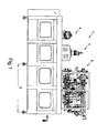
- Fig. 1 3 shows the front view of a basic machine 1.
- the basic machine preferably consists essentially of a sterilization zone 2, a filling machine 3 and a closing machine 4.
- the media preparation 5 is preferably positioned on the roof of the installation 1.
- the treated media are preferably fluids, in particular liquids, such as drinks, flowable foods and the like, as well as auxiliary media such as (sterile) gases, (sterile) water, disinfectants.
- the container treatment plant preferably has a plurality of transfer units 13, at least one container treatment zone 2 for sterilizing the containers, a filling device 3, a closing device 4 and a dry zone along the conveying line F1 between inlet lock 6 and outlet lock 9, wherein preferably a further sterilization chamber 23 is present the closures are fed by gravity of the closing machine 4. It is also conceivable that the container and closure sterilization are arranged in a chamber.
- temperate containers are particularly preferably processed from a container manufacturing machine 19 and a cross table K is docked with several conveyor lines as inlet module 12. It is also conceivable that a cross table K is docked for merging several conveyor lines as outlet module 31.
- the cross table may also preferably be combined with preform sterilization container treatment plants.
- a conveyor line then consists, for example, of preform feed, stretch blow molding machine with preform sterilization module (in front of the heating oven, in the heating oven, between heating oven and blowing wheel or directly in the blowing wheel), cross table, filler, optionally with intermediate transport devices. More preferably, the treatment unit 8 has two sections b / c, in which the containers are treated at different temperatures.
- Fig. 2 shows a plan view of the basic machine of the system, which may for example represent a second container treatment plant.
- a housing in particular an insulator housing 33, there are at least one treatment unit 7 with a treatment fluid, in particular a gas such as H2O2, a treatment unit 8 with at least one further medium such as sterile air, a container filling unit 3 and / or a closure unit 4
- the outlet lock 9 is integrated into the housing. Due to the manufacturing, the insulator housing 33 is limited in length, width and height, therefore, the inlet lock 6 and / or especially the outlet housing may be integrated into the welded part of the housing, but this need not be the case in every embodiment. Because of the carryover of media in the insulator housing 33, the individual treatment units 3/4/7/8 are preferably separated by partitions 14. Transfer units 13 transport the containers from one treatment center to the next.
- the inlet module 12 can be a stretch blow molding machine, a container distribution unit, a container preheating unit or, in the simplest case, a transfer unit, in particular with air transport.
- the insulator housing 33 and its internals may preferably be cleaned with caustic and after a drying phase with a further medium, such as H2O2 gas sterilized.
- a pedestal 11 is preferably present.
- Fig. 3 shows a front view of an advantageous block variant.
- the aseptic system 1 is preferably provided with a stretch blow molding machine 19, e.g. may be a first container handling device, blocked, i. the transport devices are preferably synchronized.
- the preforms are brought to sorting 16 via a feed unit 15. Then they are conveyed via a transport unit, e.g. a chute, actively or passively promoted in the heater 17.
- a transport unit e.g. a chute
- an air rinser (not shown) is preferably installed between the sorting and the heating wheel.
- the containers are shaped and then transferred via a transfer unit to the sterilization and bottling plant.
- FIG. 3 An advantageous arrangement of the shutter 20, is eg in Fig. 3 shown.
- a double cascade it is possible, for example, to provide different, in particular several, for example two or three different types of closure.
- An inspection unit 22 may be provided for checking the closures, in particular for dimensional stability, before the closures are supplied to the closure sterilization chamber 23.
- the closures therefore preferably slide in a channel through the chamber 23 due to their own gravitational pull.
- the oblique arrangement of the chamber (angle of attack of 15-90 °, preferably 25-40 ° and particularly preferably approximately 30 ° or 30 °). treatment time is gained.
- the closures are also treated with at least one gas, in particular H2O2.
- a unit for controlling the closure speed is present on or in the chamber in order to ensure a certain treatment time.
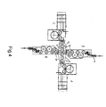
- Fig. 4 shows a block version with cross table to gain more flexibility with very short changeover times.
- containers of a particular shape and size eg, 500ml containers
- machine A containers of a particular shape and size (eg, 500ml containers) can be made.
- machine B can z. B. be a filling machine that fills a drink, such as strawberry juice with red cap.
- Machine C provides z. B. container forth with a different size (eg., 1000ml container) as a machine A.
- the filling machine D fills, for example, another drink, such as grape juice, For example, it closes and closes with a blue shutter.
- the conveyor line F2 represents the container track from the machine C via the cross table to the machine D.
- two end products can be produced, e.g. Grape juice with blue cap in 1000ml container and strawberry juice with red cap in 500ml container.
- the cross table or the transport device is thus preferably composed of the three or four transport stars T 51 , T 52 , T 53 , T 54 , which are particularly preferably each driven by servo motors.
- the transport stars or gripping elements of the transport stars can transfer the transported containers coming from the first treatment device to one of two further transport stars. This is done, for example, such that containers are conveyed via the transport star T 51 to the transport star T 52 . If a production change to be made, so for example, by new or reconfiguration of the controller or the driving of the transport star T 51, T 52, T 53, T 54, the recruitment of new conveyance paths.
- the containers no longer passes to the transport star T 52 , but to the transport star T 54 .
- the production change for the transport star T 53 this then promotes namely the containers no longer to the transport star T 54 , but to the transport star T 52 .
- a production change can also be effected by the transport stars T 51 , T 52 , T 53 , T 54 are rotated in their entirety as a cross table such that, for example, the transport star T 51 assumes the position of the transport star T 54 . It is advantageous that none of the two stretch blow molding machines must be converted to another container, which is usually very time consuming. Furthermore, the filling products can remain in the respective filling machines, so that the filling machines do not have to be rinsed or cleaned / sterilized.
- Fig. 5 shows the easy change of production.
- Machine A now supplies machine D and machine C via conveyor line F3 via conveyor line F4 machine B.
- the final products can then be grape juice with blue cap in 500ml container and strawberry juice with red cap in 1000ml container.
- a cross table K is particularly suitable for systems in the low power range, since usually no buffer distances between the machines are required and the individual machines still occupy relatively small footprint. If hygiene is particularly important during production, the mechanical stage can also be used like the one in Fig. 2 shown machine, automated cleaned and / or sterilized, since it is preferably integrated in the insulator housing. In production, for example, through installed ventilation technology, the housing of the cross table be subjected to an overpressure.
- tank handling units may be installed on the transfer units (T1, T2, T3, T4). It is conceivable that treatments by means such as e.g. a container preheating unit, container sterilization unit or treatments such as e.g. Container cooling, z. As with carbonated drinks, the container identification (dating, bar code) and / or the container labeling are feasible.
- a container ejecting device 24 may expediently be present at the cross table or the transport device.
- a container lock 28 or a lock lock 32 is present on the conveyor lines F1 / F2 or V between the container sterilization 2 or the closure sterilization 23 and the machine outlet 27/31.
- each machine is preferably equipped with one or more servo axes.
- the respective control is preferably carried out by a control unit, not shown, corresponding to a selectable production program.
- the XY stage is S1 / S2 / S3 and S4, as in FIG Fig. 5 shown, equipped.
- the conveyor lines F3 and F4 (or F1 and F2) can be occupied with different production outputs.
- the output of conveyor line F3 can be 12,000 containers per hour with 500ml grape juice and that of conveyor line F4 10,000 containers per hour with 1000ml strawberry juice.
- Fig. 6 shows a further block variant with cross table K.
- each inlet module 12 is installed at the aseptic filling systems B and D.
- the containers are in this example via a respective transport unit, such. an air transporter 26, the system supplied.
- the conveyor lines F1 / F2 converge at the cross table and the containers are then provided with a label in the labeling machine E.
- the aseptic processing machine 1 is blocked with a labeling machine E (with one or more units E1 / E2, etc.).
- the first container treatment device preforms can be formed into bottles, that is, the first container treatment device may be e.g. can be designed as a blowing machine, and with the second container treatment device, the bottles can be filled, that is, that the second container treatment device, for. a filler can be.
- the first container treatment device performs the filling of the bottles or containers and the second container treatment device is a labeling device.
- both conveyor lines preferably produce between 6000 and 18000 containers per hour and more preferably about 12 000 containers per hour.
- both conveyor lines run with the same power.
- a bottle contents corresponding label on the container can be applied.
- the plant controller and / or a scanner 25 ensures that the corresponding label is associated with the container with the corresponding bottle contents. It is conceivable that the containers which are conveyed on the conveyor lines 1 and 2, an identification feature, for. B. in the form of a barcode.
- Every second container then has a different content / closure and label over its direct predecessor. This makes it possible to pack units of two different types in the packaging line.
- a six-pack of 3x grape juice and 3x strawberry juice can be produced.
- Such a system may be referred to, for example, as a 2-color filling system.
- the labeling machine E can be blocked directly to a processing machine 1.
- the sealed containers arc traded over transport stars T n . Since in many cases the closure covers one or more support rings of the containers, the containers can no longer be transported consistently via a gripper system. It is therefore preferable for the containers to be conveyable via transport elements, such as, for example, one or more neck pockets or via a height-adjustable bottom support element. Such a ground support element is in DE102009058084.0 and is incorporated by reference in its entirety into the subject matter of this invention.
- a treatment step (sterilization / filling and / or closing) of one or more containers is not completed.
- Such containers can preferably be taken from the conveyor line F1 or F2 by means of a transport star T4 via a lock 28.
- Detected faulty treatment steps or containers by a sensor that on the conveyor line and / or in the Treatment elements is providable.
- the system controller remembers (for example by means of a shift register) an incorrectly treated container, determines the partner container in the other conveyor line and gives the command to a transport star, such as the transport star T3 or T4, either from T1 to T3 not to take over, or from T1 or T2 to T4.
- An ejector 24 removes the containers from the transport system.
- This system is particularly advantageous for contamination in the downstream machines and plant components, such.
- As the labeling machine E to avoid by not closed container. However, it is also possible to take faulty containers in the conveying direction after the cross table via an ejector from production. Then, instead of the container lock 28, a third aseptic filling installation may be docked. Consequently, preferably the cross table K is equipped with a modified container transport system and the labeling machine E is preferably equipped with three units. It is therefore possible to supplement or expand the system to the 3-color system.
- an intake module 12 is shown, which is fed via an air conveyor 26 with containers.
- This inlet module 12 or any inlet module 12 may preferably be designed as a cross table.
- a container preheating unit 29 may be in use. This has a positive effect on residues, for example in the case of sterilization, such as dry H2O2 sterilization, in particular in the case of plastic containers, such as in PET containers. For other container materials, such. B. HDPE, it is conceivable that can be dispensed preheating the container.
- Container sterilization processes are subject to z. T. also legally regulated country-specific approvals, the z. B. do not provide the preheating of the container.
- the system can be adapted to country-specific requirements.
- the treatment units 3/4/7/8 are limited in size, thus the system performance is eg at a 500ml container at about 12 000 B / h.
- the plant performance can be increased, for example, if the blind spot d partially is occupied to extend the treatment time. About 10 to 15% more power is achievable.
- an overpressure to the environment is to be maintained (for example, p 1 ⁇ p at + 10 Pa) (see Fig. 7 ). This is ensured, for example, via several supply air nozzles Z1 / Z2, etc.
- the supply air for example, in the upper part of the housing attached and the exhaust air A1 / A2, etc., for example, in the lower area.
- process air P1 / P2 is supplied to the system in the production, which also acts in the pressure balance.
- the regulation takes place eg via flaps K and / or via a speed control of the supply air fans.
- At least one pressure sensor and / or a control device monitors that the limit value of p 1 is not undershot.
- the supply air can be processed centrally or decentrally by means of filters, in particular sterilizable filters.
- the exhaust air is preferably connected to a manifold and discharged into the environment.
- a scrubber is also or alternatively providable.
- the insulator sterilization (for example by means of hot H2O2 gas) is carried out via the supply air system.
- the insulator housing 33 is preferably a welded construction made of sheet metal, since this provides optimal microbiological safety.
- the base plate 35 (see Fig. 8 ) consists preferably of at least one bottom plate 37 and at least one roof plate 36.
- the base plate in the longitudinal direction (because of the thermal expansion) provided with stiffeners 38.
- stiffeners 38 are preferably welded into the baseplate.
- the sheets 41 of the insulator housing 33 are preferably attached.
- the housing can also be provided with stiffeners.
- supply and exhaust pipes, and cleaning lines and processes are integrated into the insulator housing. In general, for example, can be used for sealing Usit sealing rings.
- flanges 39 are preferably the bearings for transfer units 13 and / or the treatment units 3/4/7/8.
- Fig. 8 the closing machine 4 is shown. It preferably consists of a bearing 45, which is protected by a sealing device, such as a sealing lip 52, from aggressive substances from the clean room.
- a sealing device such as a sealing lip 52
- On the drive shaft for example, a support plate 47 is fixed, on which in turn the closing elements are mounted or mounted.
- a cam roller 48 preferably moves the casting element 4 up and down.
- a bellows 50 is preferably provided.
- a servo motor 49 is arranged outside the clean room. The rotational movements are usually performed by means of shafts and shaft seal in the clean room. However, a magnetic coupling can also be provided here.
- the torque is preferably transmitted via a power transmission device, such as e.g. a gear pair 51, transferred to the sealing cone.
- a power transmission device such as e.g. a gear pair 51
- Container and closure 44 are transferred to the closing machine 4 via one or more transfer units.
- a closure inspection unit 22 is present between a closure sorting 20 and the closure sterilization chamber 23.
- the containers are arranged on container supports, not shown.
- Fig. 9 is an example of a preferred arrangement of a plurality of interconnected and / or shown at least temporarily or successively or directly or indirectly cooperating devices.
- the number of devices may be less than, equal to or greater than those in Fig. 9 be shown number.
- Fig. 9 arrangement shown is advantageous since the containers can preferably be conveyed upstream and / or downstream, depending on production conditions.
- containers in a first configuration preferably preforms
- the containers in a first configuration can be supplied, for example, to a mechanical stage K, in order subsequently to be conveyed, for example, to one or more container production machines.
- the containers can be supplied for further and / or initial treatment, for example to an aseptic container treatment machine 1.
- the containers can be supplied via a further treatment device, such as a labeling machine E, a packaging or labeling area or device 54.
- a further treatment device such as a labeling machine E, a packaging or labeling area or device 54.
- the packaging or labeling area preferably extends along one side of the part of the installation described above, wherein it is also conceivable that the packaging or labeling area extends on both sides of this part of the installation.
Abstract
Description
Die Erfindung ist auf eine Anlage zum Behandeln von Behältnissen, insbesondere Vorformlingen und/oder Flaschen, gemäß dem Oberbegriff des Patentanspruches 1 und ein Verfahren gemäß dem Oberbegriff des Patentanspruchs 14 gerichtet.The invention is directed to a system for treating containers, in particular preforms and / or bottles, according to the preamble of
Die Druckschrift
Die Druckschrift
Speziell für den niedrigen Leistungsbereich (bis ca. 12000 Behälter pro Stunde) werden Maschinen benötigt, welche sterile Produkte in sterile Behälter füllen, da häufig Chargen geringer Größe und kommissionsbedingtes Abfüllen gefordert wird.Especially for the low performance range (up to approx. 12,000 containers per hour), machines are required which fill sterile products into sterile containers, since small batches and commission-related filling are frequently required.
Es ist daher Aufgabe der vorliegenden Erfindung eine möglichst flexible und günstige Anlage zum Behandeln von Behältnissen bereitzustellen.It is therefore an object of the present invention to provide a flexible and convenient plant for treating containers.
Die Lösung der zuvor gestellten Aufgabe erfolgt erfindungsgemäß durch eine Anlage zum Behandeln von Behältnissen, insbesondere Vorformlingen und/oder Flaschen. Diese Anlage umfasst mindestens eine erste Behälterbehandlungseinrichtung und eine im Transportpfad der Behältnisse nachgelagerte zweite Behälterbehandlungseinrichtung und eine Transporteinrichtung zum zumindest abschnittsweisen Fördern der Behältnisse von der ersten Behälterbehandlungseinrichtung zur zweiten Behälterbehandlungseinrichtung. Erfindungsgemäß ist eine weitere erste und/oder zweite Behälterbehandlungseinrichtung mit der Transporteinrichtung verbunden, die mindestens zwei direkte und zumindest abschnittsweise unterschiedliche Transportpfade der Behältnisse ausbildet. Das Behandeln von Behältnissen umfasst bevorzugt das Umformen, Reinigen, Sterilisieren, Verpacken, Sortieren, Temperieren, Befüllen, Verschließen, Etikettieren, Kombinationen daraus und/oder ähnliches. Es ist zudem vorstellbar, dass mehrere erste und zweite Behälterbehandlungseinrichtungen vorgesehen sind, insbesondere genau zwei erste und genau zwei zweite Behälterbehandlungseinrichtungen.The solution of the above object is achieved by a system for treating containers, in particular preforms and / or bottles. This system comprises at least a first container treatment device and a downstream in the transport path of the containers second container treatment device and a transport device for at least partially conveying the containers from the first container treatment device to the second container treatment device. According to the invention, a further first and / or second container treatment device is connected to the transport device, which forms at least two direct and at least partially different transport paths of the containers. The treatment of containers preferably comprises forming, cleaning, sterilizing, packaging, sorting, tempering, filling, sealing, labeling, combinations thereof and / or the like. It is also conceivable that a plurality of first and second container treatment devices are provided, in particular exactly two first and exactly two second container treatment devices.
Diese Lösung ist vorteilhaft, da über die unterschiedlichen Transportpfade die Behältnisse zu den entsprechenden Behandlungseinrichtungen geführt werden können, wodurch keine aufwändige Umrüstung der Anlage erforderlich ist. Aufgrund der direkten Transportpfade wird ferner auf Puffer verzichtet, wodurch die Vorrichtung bzw. Anlage ebenfalls sehr günstig herzustellen ist und wenig Platz benötigt. Um mehr Flexibilität bei der Produktion zu erhalten können beispielsweise auch mehrere Anlagen parallel installiert werden.This solution is advantageous because the containers can be guided to the corresponding treatment facilities via the different transport paths, whereby no complex conversion of the system is required. Due to the direct transport paths is also dispensed with buffer, whereby the device or system is also very cheap to produce and requires little space. For example, several systems can be installed in parallel to increase production flexibility.
Direkt beschreibt in diesem Zusammenhang bevorzugt eine Anordnung ohne Pufferstrecke bzw. dass die Behältnisse auf dem kürzesten Weg mit den jeweiligen Transporteinrichtungen zu der nächsten Behandlungseinrichtung führbar sind. Direkt kann somit aber auch bedeuten, dass der gewählte Transportpfad nicht verlassen wird, wie die z.B. beim Einsatz von Puffern erfolgt.Direct describes in this context preferably an arrangement without buffer line or that the containers are feasible on the shortest path with the respective transport devices to the next treatment facility. Direct can therefore also mean that the selected transport path is not left, as is the case, for example, when using buffers.
Gemäß einer weitern bevorzugten Ausführungsform der vorliegenden Erfindung weist die Transporteinrichtung mehrere Rotationsförderer, insbesondere Transportsterne, auf. Besonders bevorzugt weist die Transporteinrichtung nur Transportsterne auf.According to a further preferred embodiment of the present invention, the transport device has a plurality of rotary conveyors, in particular transport stars. Particularly preferably, the transport device has only transport stars.
Diese Ausführungsform ist vorteilhaft, da Transportsterne äußerst einfach steuerbar sind, wodurch die Übergabe von Behältnissen sehr präzise und schnell erfolgen kann.This embodiment is advantageous because transport stars are extremely easy to control, whereby the transfer of containers can be done very precisely and quickly.
In einer weitern bevorzugten Ausführungsform der vorliegenden Erfindung weist die Transporteinrichtung mindestens drei Transportsterne und bevorzugt mindestens vier bzw. genau vier Transportsterne auf.In a further preferred embodiment of the present invention, the transport device has at least three transport stars and preferably at least four or exactly four transport stars.
Diese Ausführungsform ist vorteilhaft, da sie die Möglichkeit eröffnet, dass jeder der Transportsterne mit einem weiteren Transportstern ausgewählt aus zwei der Transportsterne funktionell verbunden ist bzw. verbindbar ist. Dies ermöglicht eine äußerst flexible Auswahl bzw. ein äußerst flexiblen Wechsel zwischen den möglichen Transportpfaden. Insbesondere können die einzelnen Transportsterne der Transporteinrichtung somit wechselseitig mit einem bzw. zwei der übrigen Transportsterne der Transporteinrichtung funktionell gekoppelt werden.This embodiment is advantageous since it opens up the possibility that each of the transport stars is functionally connected or connectable to another transport star selected from two of the transport stars. This allows a very flexible selection or a very flexible change between the possible transport paths. In particular, the individual transport stars of the transport device can thus be mutually functionally coupled to one or two of the other transport stars of the transport device.
Gemäß einer weiteren bevorzugten Ausführungsform der Erfindung sind mit den Transportsternen weitere Transporteinrichtungen verbunden.According to a further preferred embodiment of the invention further transport devices are connected to the transport stars.
Somit bilden die drei oder vier Transportsterne bevorzugt eine Einrichtung bzw. eine Einheit, die auch z. B. baulich durch einen gemeinsamen Tisch, insbesondere einem Kreuztisch oder ähnlichem, von weiteren Einrichtungen getrennt angeordnet bzw. anordenbar ist. Die Gesamtheit der Transportsterne der Transporteinheit der vorliegenden Erfindung kann daher auch als Zuordnungseinrichtung zum Zuordnen bzw. definierten Schleusen von Behältnissen angesehen werden. Die weiteren Transporteinrichtungen können ebenfalls als Rotationsförderer und/oder Linearförderer ausgebildet sein und dienen bevorzugt dazu, die Behältnisse der ersten und/oder der zweiten Behandlungseinrichtung ab- oder zuzuführen.Thus, the three or four transport stars preferably form a device or a unit which also z. B. structurally separated by a common table, in particular a cross table or the like, from other devices arranged or can be arranged. The totality of the transport stars of the transport unit of the present invention can therefore also be regarded as an allocation device for allocating or defining locks of containers. The further transport devices can likewise be designed as rotary conveyors and / or linear conveyors and are preferably used to remove or supply the containers to the first and / or the second treatment device.
Gemäß einer weiteren bevorzugten Ausführungsform der vorliegenden Erfindung weisen die Transportsterne der Transporteinrichtung jeweils eigene Antriebe auf.According to a further preferred embodiment of the present invention, the transport stars of the transport device each have their own drives.
Diese Ausführungsform ist vorteilhaft, da die Transportsterne aufgrund eigener Antriebe, die beispielsweise elektrisch, hydraulisch, pneumatisch, mechanisch, Kombinationen daraus und/oder ähnlich angetrieben sein können, eine definierte Anpassung an die jeweiligen Zuführ- und/oder Abführgeschwindigkeiten der vor- und/oder nachgelagerten Einrichtungen ermöglicht.This embodiment is advantageous because the transport stars due to their own drives, which may be driven, for example, electrically, hydraulically, pneumatically, mechanically, combinations thereof and / or similar, a defined adaptation to the respective supply and / or Abführgeschwindigkeiten of forward and / or downstream facilities.
Gemäß einer weiteren bevorzugten Ausführungsform der vorliegenden Erfindung weisen die Transportsterne Greifelemente auf, die bevorzugt zumindest teilweise steuerbar sind, d.h., dass die Greifelemente bevorzugt definiert geöffnet und geschlossen werden können..According to a further preferred embodiment of the present invention, the transport stars on gripping elements, which are preferably at least partially controllable, that is, that the gripping elements can be opened and closed preferably defined.
Es ist zudem denkbar, dass auch die Geschwindigkeit der Transportsterne z. B. in Abhängigkeit vom Transportweg konfigurierbar bzw. einstellbar ist. Im Falle verschiedener Transportwege können beispielsweise die Behältnisse im ersten Transportweg schneller als in einem weiteren Transportweg gefördert werden. Ferner ist diese Ausführungsform vorteilhaft, da das Aufnehmen und Abgeben bzw. Übergeben von Behältnissen definiert durchführbar ist. Dies ist selbst bei hohen Drehgeschwindigkeiten der Transportsterne möglich. Die Steuerung der Greifelemente kann dabei über Positionsdaten, d. h. beispielsweise über eine motorisierte Ansteuerung, und/oder über Steuerkurven bewirkt werden. Bevorzugt ist eine Sensoreinrichtung und/oder eine Steuereinrichtung zum Überwachen, Steuern und/oder Verändern der Abläufe vorgesehen bzw. mit der Anlage gekoppelt.It is also conceivable that the speed of the transport stars z. B. is configurable or adjustable depending on the transport route. In the case of different transport routes, for example, the containers in the first transport can be promoted faster than in another transport. Furthermore, this embodiment is advantageous since the picking and dispensing of containers is defined feasible. This is possible even at high speeds of rotation of the transport stars. The control of the gripping elements can via position data, d. H. be effected for example via a motorized control, and / or via cams. Preferably, a sensor device and / or a control device for monitoring, controlling and / or changing the processes is provided or coupled to the system.
Gemäß einer weiteren bevorzugten Ausführungsform der vorliegenden Erfindung ist die erste Behälterbehandlungseinrichtung eine (Streck-)Blaseinrichtung zum Umformen von Vorformlingen in Flaschen.According to another preferred embodiment of the present invention, the first container treatment device is a (stretch) blowing device for forming preforms in bottles.
Diese Ausführungsform ist vorteilhaft, da das Umformen der Vorformlinge in Behältnisse zeitlich und räumlich sehr nah zum Zeitpunkt der Abfüllung bzw. weiterer Behandlungsschritte erfolgt. Dies ermöglicht einen einfachen und stabilen Transport der Behältnisse über große Strecken, da die Behältnisse in Form von Vorformlingen zum einen eine wesentlich kleinere Größe aufweisen als das bearbeitete bzw. umgeformte Behältnis und die Vorformlinge wesentlich robuster sind als umgeformte Behältnisse.This embodiment is advantageous since the forming of the preforms in containers takes place very close in time and space to the time of filling or further treatment steps. This allows a simple and stable transport of the containers over long distances, since the containers in the form of preforms on the one hand have a much smaller size than the processed or reshaped container and the preforms are much more robust than molded containers.
Gemäß einer weiteren bevorzugten Ausführungsform der vorliegenden Erfindung ist die zweite Behälterbehandlungseinrichtung ein Modul zur (aseptischen) Abfüllung von Behältnissen und/oder eine Einrichtung zum Etikettieren der Behältnisse.According to a further preferred embodiment of the present invention, the second container treatment device is a module for (aseptic) filling of containers and / or a device for labeling the containers.
Diese Ausführungsform ist vorteilhaft, da nach der Umformung der Vorformlinge in Behältnisse eine baldige Weiterbehandlung dieser Behältnisse möglich ist. Dies ermöglicht z. B., dass keine Lager zum Aufbewahren umgeformter bzw. gefüllter Behältnisse vorgesehen werden müssen.This embodiment is advantageous because after the deformation of the preforms in containers, a rapid further treatment of these containers is possible. This allows z. B. that no storage for storing reshaped or filled containers must be provided.
Gemäß einer weiteren bevorzugten Ausführungsform der vorliegenden Erfindung weist das Modul zur aseptischen Abfüllung ein Gehäuse auf, durch das ein Reinraum ausgebildet ist und in dem die Behältnisse desinfizierbar, abfüllbar und/oder verschließbar sind.According to a further preferred embodiment of the present invention, the module for aseptic filling a housing, through which a clean room is formed and in which the containers are disinfected, filled and / or closed.
Diese Ausführungsform ist vorteilhaft, da mehrere Einrichtungen zum besseren Transport und/oder gemeinsamen Ausbilden eines Reinraums und somit zum Reduzieren der Komplexität, der Anzahl an Bauteilen, des Energieverbrauchs und ähnlichem funktionell miteinander koppelbar sind.This embodiment is advantageous because a plurality of devices for better transport and / or joint formation of a clean room and thus to reduce the complexity, the number of components, energy consumption and the like are functionally coupled together.
Gemäß einer weiteren bevorzugten Ausführungsform der vorliegenden Erfindung ist im Transportpfad, insbesondere in der Transporteinrichtung und/oder in dem Modul zur aseptischen Abfüllung, mindestens eine Behälterausstoßeinrichtung zum Ausstoßen fehlerhaft behandelter Behältnisse angeordnet.According to a further preferred embodiment of the present invention, at least one container ejection device is arranged in the transport path, in particular in the transport device and / or in the module for aseptic filling, for ejecting incorrectly treated containers.
Diese Ausführungsform ist vorteilhaft, da defekte bzw. mangelhafte Behältnisse beispielsweise direkt nach der Detektion der als mangelhaft bewerteten Eigenschaft oder zu einem späteren geeigneterem Zeitpunkt aus der Anlage bzw. den Transportpfad der Behältnisse ausschleusbar ist. Dies ermöglicht die Einsparung von Kosten, da ein bereits frühzeitig als mangelhaft erkanntes Behältnis nicht weiter behandelt werden muss, wodurch die Einsparung beispielsweise von Reinigungsfluiden, Energie, Befüllmittel und Ähnlichem erfolgen kann.This embodiment is advantageous because defective or defective containers, for example, directly after the detection of the property assessed as deficient or at a later suitable time from the plant or the transport path of the containers ausschleusbar. This makes it possible to save on costs, since a container which has already been recognized to be defective at an early stage does not need to be further treated, as a result of which the saving of, for example, cleaning fluids, energy, filling agent and the like can take place.
Gemäß einer weiteren bevorzugten Ausführungsform der vorliegenden Erfindung ist ein erster Teil der Behältnisse über einen ersten Transportpfad förderbar und ein zweiter Teil der Behältnisse ist über mindestens einen weiteren Transportpfad förderbar, wobei mindestens ein Transportstern zeitweise den ersten Transportpfad und zeitweise den weiteren Transportpfad mit ausbildet. Bevorzugt ist jeder dieser Transportsterne wahlweise zumindest zeitweise mit nur einem weiteren Transportstern gekoppelt bzw. wirkt nur mit diesem zusammen, d. h. bildet einen Transportpfad mit diesem aus.According to a further preferred embodiment of the present invention, a first part of the containers is conveyable via a first transport path and a second part of the Containers can be conveyed via at least one further transport path, with at least one transport star temporarily forming the first transport path and, at times, the further transport path. Preferably, each of these transport stars is optionally at least temporarily coupled with only one further transport star or acts only with this, ie forms a transport path with this.
Diese Ausführungsform ist vorteilhaft, da einzelne Transportsterne oder beliebige Transportmittel durch eine veränderte Ansteuerung und somit ohne aufwändige Umrüsttätigkeiten zur Ausbildung verschiedener Transportpfade verwendet werden kann.This embodiment is advantageous because individual transport stars or any means of transport can be used by a modified control and thus without complex Umrüsttätigkeiten to form different transport paths.
Gemäß einer weiteren bevorzugten Ausführungsform der vorliegenden Erfindung sind die Behältnisse mit der Transporteinrichtung zumindest zeitweise auf demselben Transportpfad transportierbar.According to a further preferred embodiment of the present invention, the containers with the transport device are at least temporarily transportable on the same transport path.
Diese Ausführungsform ist vorteilhaft, da z. B. verschiedene oder gleiche Behältnisse von zwei ersten Behandlungseinrichtungen kommend in einer zweiten Behandlungseinrichtung behandelt, insbesondere gleich behandelt, werden können.This embodiment is advantageous because z. B. different or identical containers from two first treatment facilities coming in a second treatment facility treated, in particular treated the same can be.
Die Erfindung ist ebenfalls auf ein Verfahren zum Behandeln von Behältnissen, insbesondere zum aseptischen Behandeln von Flaschen, gerichtet. Das Verfahren umfasst zumindest die Schritte des Behandelns von Behältnissen mit mindestens einer ersten Behälterbehandlungseinrichtung und mit einer zweiten Behälterbehandlungseinrichtung, wobei die Behälter zumindest abschnittsweise mit einer Transporteinrichtung von der ersten Behandlungseinrichtung zu der zweiten Behandlungseinrichtung gefördert werden. Erfindungsgemäß ist eine weitere erste oder zweite Behälterbehandlungseinrichtung mit der Transporteinrichtung verbunden und die Behältnisse werden von der Transporteinrichtung abschnittsweise auf mindestens zwei Transportpfaden, bevorzugt direkt, transportiert.The invention is also directed to a method for treating containers, in particular for aseptically treating bottles. The method comprises at least the steps of treating containers with at least one first container treatment device and with a second container treatment device, wherein the containers are conveyed at least in sections with a transport device from the first treatment device to the second treatment device. According to the invention, a further first or second container treatment device is connected to the transport device and the containers are transported by the transport device in sections to at least two transport paths, preferably directly.
Weitere, Vorteile, Ziele und Eigenschafen vorliegender Erfindung werden anhand nachfolgender Beschreibung anliegender Zeichnungen erläutert, in welchen beispielhaft aseptische Abfüllanlagen dargestellt sind. Bauteile der aseptischen Anlagen, welche in den Figuren wenigstens im Wesentlichen hinsichtlich ihrer Funktion übereinstimmen, können hierbei mit gleichem Bezugszeichen gekennzeichnet sein, wobei diese Bauteile nicht in allen Figuren beziffert oder erläutert sein müssen.Further advantages, objects and features of the present invention will be explained with reference to the following description of appended drawings, in which exemplary aseptic filling systems are shown. Components of the aseptic systems, which in the figures at least substantially coincide with regard to their function, can hereby be identified by the same reference character, these components not having to be numbered or explained in all the figures.
Darin zeigen:
- Fig. 1
- eine Frontansicht der Grundmaschine;
- Fig. 2
- eine Draufsicht der Grundmaschine der Anlage;
- Fig. 3
- eine Frontansicht einer vorteilhaften Blockvariante;
- Fig. 4
- eine Blockvariante mit Kreuztisch;
- Fig. 5
- eine Darstellung eines Produktionswechsels;
- Fig. 6
- eine weitere Blockvariante mit Kreuztisch;
- Fig. 7
- eine weitere Ausführungsform der Grundmaschine;
- Fig. 8
- einen Querschnitt durch ein Modul einer aseptischen Abfüllanlage; und
- Fig. 9
- ein Beispiel einer bevorzugten Anordnung einer Vielzahl an Anlagenkomponenten.
- Fig. 1
- a front view of the basic machine;
- Fig. 2
- a plan view of the basic machine of the plant;
- Fig. 3
- a front view of an advantageous block variant;
- Fig. 4
- a block version with cross table;
- Fig. 5
- a representation of a change of production;
- Fig. 6
- another block variant with cross table;
- Fig. 7
- another embodiment of the basic machine;
- Fig. 8
- a cross section through a module of an aseptic filling plant; and
- Fig. 9
- an example of a preferred arrangement of a variety of plant components.
Es ist ebenfalls denkbar, dass ein Einlaufmodul 12 mit Vorwärmeinheit 29 vorhanden ist. Besonders bevorzugt werden temperierte Behälter aus einer Behälterherstellmaschine 19 verarbeitet und ein Kreuztisch K mit mehreren Förderlinien als Einlaufmodul 12 angedockt ist. Denkbar ist ebenfalls, dass ein Kreuztisch K zur Vereinigung mehrerer Förderlinien als Auslaufmodul 31 angedockt ist. Mit dem Kreuztisch können bevorzugt auch Behälterbehandlungsanlagen mit Vorformlings-Sterilisation verknüpft werden. Eine Förderlinie besteht dann beispielsweise aus Preformzuführung, Streckblasmaschine mit Vorformlings-Sterilisationsmodul (vor dem Heizofen, im Heizofen, zwischen Heizofen und Blasrad oder direkt im Blasrad), Kreuztisch, Füller, gegebenenfalls mit zwischengeschalteten Transporteinrichtungen. Weiter bevorzugt weist die Behandlungseinheit 8 zwei Sektionen b/c auf, in denen die Behälter mit unterschiedlichen Temperaturen behandelt werden.It is also conceivable that an
Je nach Anforderung kann das Einlaufmodul 12 eine Streckblasmaschine, eine Behälterverteileinheit, eine Behältervorwärmeinheit oder im einfachsten Fall eine Transfereinheit, insbesondere mit Lufttransport, sein.Depending on the requirement, the
Zur Produktionsvorbereitung können das Isolatorgehäuse 33 und deren Einbauten vorzugsweise mit Lauge gereinigt und nach einer Trocknungsphase mit einem weiteren Medium, wie z.B. H2O2-Gas, sterilisiert werden. Um die Zugänglichkeit der Medienaufbereitung zu gewähren ist bevorzugt ein Podest 11 vorhanden.For production preparation, the
Die Aseptikanlage 1 ist bevorzugt mit einer Streckblasmaschine 19, die z.B. eine erste Behälterbehandlungseinrichtung sein kann, geblockt, d.h. die Transporteinrichtungen sind bevorzugt synchronisiert. Die Vorformlinge werden über eine Zuführeinheit 15 zur Sortierung 16 gebracht. Dann werden sie über eine Transporteinheit, wie z.B. eine Rutsche, aktiv oder passiv in den Heizofen 17 gefördert. Um die Vorformlinge zu reinigen, insbesondere von Staubpartikeln, ist bevorzugt zwischen Sortierung und Heizrad ein Luftrinser (nicht gezeigt) eingebaut. In der Streckblaseinheit 18 werden die Behälter ausgeformt und dann über eine Transfereinheit an die Sterilisations- und Abfüllanlage übergeben.The
Eine vorteilhafte Aufstellung der Verschlusszuführung 20, ist z.B. in
Maschine C stellt z. B. Behälter her mit einer anderen Größe (z. B. 1000ml-Behälter) als Maschine A. Die Füllmaschine D füllt zum Beispiel ein weiteres Getränk, wie z.B. Traubensaft, ab und verschließt es z.B. mit einem blauen Verschluss. Die Förderlinie F2 repräsentiert die Behälterlaufbahn von der Maschine C über den Kreuztisch zur Maschine D.Machine C provides z. B. container forth with a different size (eg., 1000ml container) as a machine A. The filling machine D fills, for example, another drink, such as grape juice, For example, it closes and closes with a blue shutter. The conveyor line F2 represents the container track from the machine C via the cross table to the machine D.
Mit dem oben gezeigten Beispiel können zwei Endprodukte produziert werden, wie z.B. Traubensaft mit blauem Verschluss im 1000ml-Behälter und Erdbeersaft mit rotem Verschluss im 500ml-Behälter.With the example shown above, two end products can be produced, e.g. Grape juice with blue cap in 1000ml container and strawberry juice with red cap in 500ml container.
Der Kreuztisch bzw. die Transporteinrichtung ist somit bevorzugt aus den drei bzw. vier Transportsternen T51, T52, T53, T54 aufgebaut, die besonders bevorzugt jeweils mit Servomotoren ansteuerbar sind. In Abhängigkeit vom ausgewählten Transportweg können die Transportsterne bzw. Greifelemente der Transportsterne die transportierten Behältnisse kommend von der ersten Behandlungseinrichtung einem von zwei weiteren Transportsternen übergeben. Dies erfolgt beispielsweise derart, dass Behältnisse über den Transportstern T51 zu dem Transportstern T52 gefördert werden. Sollte ein Produktionswechsel vorgenommen werden müssen, so erfolgt beispielsweise durch Neu- bzw. Umkonfiguration der Steuerung bzw. der Ansteuerung der Transportsterne T51, T52, T53, T54 die Einstellung neuer Förderwege. D.h., dass nach einem derartigen Produktionswechsel der Transportstern T51 die Behältnisse nicht mehr an den Transportstern T52, sondern an den Transportstern T54 übergibt. Ähnlich erfolgt der Produktionswechsel für den Transportstern T53, dieser fördert dann nämlich die Behältnisse nicht mehr zu dem Transportstern T54, sondern zu dem Transportstern T52. Ein Produktionswechsel kann ebenfalls dadurch bewirkt werden, dass die Transportsterne T51, T52, T53, T54 in ihrer Gesamtheit als Kreuztisch derart rotiert werden, dass z.B. der Transportstern T51 die Position des Transportsterns T54 einnimmt. Vorteilhaft ist dabei, dass keine der beiden Streckblasmaschinen auf einen anderen Behälter umgerüstet werden muss, was üblicherweise sehr zeitaufwändig ist. Weiterhin können die Abfüllprodukte in den jeweiligen Füllmaschinen verbleiben, so dass die Füllmaschinen nicht gespült oder gereinigt/sterilisiert werden müssen.The cross table or the transport device is thus preferably composed of the three or four transport stars T 51 , T 52 , T 53 , T 54 , which are particularly preferably each driven by servo motors. Depending on the selected transport path, the transport stars or gripping elements of the transport stars can transfer the transported containers coming from the first treatment device to one of two further transport stars. This is done, for example, such that containers are conveyed via the transport star T 51 to the transport star T 52 . If a production change to be made, so for example, by new or reconfiguration of the controller or the driving of the transport star T 51, T 52, T 53, T 54, the recruitment of new conveyance paths. That is, after such a production change of the transport star T 51, the containers no longer passes to the transport star T 52 , but to the transport star T 54 . Similarly, the production change for the transport star T 53 , this then promotes namely the containers no longer to the transport star T 54 , but to the transport star T 52 . A production change can also be effected by the transport stars T 51 , T 52 , T 53 , T 54 are rotated in their entirety as a cross table such that, for example, the transport star T 51 assumes the position of the transport star T 54 . It is advantageous that none of the two stretch blow molding machines must be converted to another container, which is usually very time consuming. Furthermore, the filling products can remain in the respective filling machines, so that the filling machines do not have to be rinsed or cleaned / sterilized.
Die Endprodukte können dann Traubensaft mit blauem Verschluss im 500ml-Behälter und Erdbeersaft mit rotem Verschluss im 1000ml-Behälter sein.The final products can then be grape juice with blue cap in 500ml container and strawberry juice with red cap in 1000ml container.
Ein Kreuztisch K ist besonders für Anlagen im niedrigen Leistungsbereich geeignet, da in der Regel keine Pufferstrecken zwischen den Maschinen benötigt werden und die Einzelmaschinen noch relativ geringe Aufstellflächen belegen. Kommt es bei der Produktion besonders auf Hygiene an, kann der Kreuztisch, ebenfalls, wie die in
Zusätzlich können auf den Transfereinheiten (T1, T2, T3, T4) Behälterbehandlungseinheiten installiert sein. Es ist dabei vorstellbar, dass Behandlungen durch Einrichtungen, wie z.B. eine Behältervorwärmeinheit, Behältersterilisationseinheit oder Behandlungen, wie z.B. Behälterkühlung, z. B. bei karbonisierten Getränken, die Behälterkennzeichnung (Datierung, Strichcode) und/oder die Behälteretikettierung durchführbar sind. Um fehlerhafte Behälter aus der Produktionslinie zu Entfernen kann zweckmäßig am Kreuztisch bzw. der Transporteinrichtung eine Behälterausstoßeinrichtung 24 vorhanden sein. Bevorzugt ist eine Behälterschleuse 28 bzw. eine Verschlussschleuse 32 an den Förderlinien F1/F2 bzw. V zwischen den Behältersterilisation 2 bzw. der Verschlusssterilisation 23 und dem Maschinenauslauf 27/31 vorhanden ist.In addition, tank handling units may be installed on the transfer units (T1, T2, T3, T4). It is conceivable that treatments by means such as e.g. a container preheating unit, container sterilization unit or treatments such as e.g. Container cooling, z. As with carbonated drinks, the container identification (dating, bar code) and / or the container labeling are feasible. In order to remove defective containers from the production line, a container ejecting device 24 may expediently be present at the cross table or the transport device. Preferably, a container lock 28 or a lock lock 32 is present on the conveyor lines F1 / F2 or V between the
Um die Einzelmaschinen A/B/C/D und K synchron und/oder unabhängig laufen lassen zu können, ist zumindest jede Maschine vorzugsweise mit einer oder mehreren Servoachse(n) ausgestattet. Die jeweilige Ansteuerung erfolgt bevorzugt durch eine nicht gezeigte Steuereinheit entsprechend einem auswählbaren Produktionsprogramm.
Vorzugsweise ist der Kreuztisch mit vier Antrieben S1/S2/S3 und S4, wie in
Preferably, with four drives, the XY stage is S1 / S2 / S3 and S4, as in FIG
Im oben genannten Beispiel kann die Ausbringung der Förderlinie F3 12 000 Behälter pro Stunde mit 500ml Traubensaft und die der Förderlinie F4 10 000 Behälter pro Stunde mit 1000ml Erdbeersaft sein.In the above example, the output of conveyor line F3 can be 12,000 containers per hour with 500ml grape juice and that of conveyor line F4 10,000 containers per hour with 1000ml strawberry juice.
An den aseptischen Abfüllanlagen B und D ist je ein Einlaufmodul 12 installiert. Die Behälter werden in diesem Beispiel über je eine Transporteinheit, wie z.B. einen Lufttransporteur 26, der Anlage zugeführt. Die Förderlinien F1/F2 laufen am Kreuztisch zusammen und die Behältnisse werden dann in der Etikettiermaschine E mit einem Etikett versehen. Bevorzugt ist die aseptische Behandlungsmaschine 1 mit einer Etikettiermaschine E (mit ein oder mehreren Aggregaten E1/E2 usw.) geblockt.At the aseptic filling systems B and D, each
Auf besondere einfache Weise können somit auf einer solchen Anlage verschieden Produkte, Behältnisse, etc. verarbeitet werden. So können beispielsweise mit der ersten Behälterbehandlungseinrichtung Vorformlinge in Flaschen umgeformt werden, d.h., dass die erster Behälterbehandlungseinrichtung z.B. als Blasmaschine ausgeführt sein kann, und mit der zweiten Behälterbehandlungseinrichtung können die Flaschen befüllt werden, d.h., dass die zweite Behälterbehandlungseinrichtung z.B. ein Füller sein kann. Es ist aber ebenfalls denkbar, dass die erste Behälterbehandlungseinrichtung das Befüllen der Flaschen bzw. Behälter durchführt und die zweite Behälterbehandlungseinrichtung eine Etikettiereinrichtung ist.In a particularly simple manner, different products, containers, etc. can thus be processed on such a system. For example, with the first container treatment device, preforms can be formed into bottles, that is, the first container treatment device may be e.g. can be designed as a blowing machine, and with the second container treatment device, the bottles can be filled, that is, that the second container treatment device, for. a filler can be. However, it is also conceivable that the first container treatment device performs the filling of the bottles or containers and the second container treatment device is a labeling device.
Zum Beispiel ist es möglich, auf der Förderlinie F1 Traubensaft mit blauem Verschluss im 500ml-Behälter und auf der Förderlinie F2 Erdbeersaft mit rotem Verschluss im 500ml-Behälter zu produzieren. Beide Linien produzieren bevorzugt zwischen 6000 und 18000 Behältnissen pro Stunde und besonders bevorzugt ca. 12 000 Behälter pro Stunde. Bevorzugt laufen beide Förderlinien mit der gleichen Leistung.For example, it is possible to produce on the conveyor line F1 grape juice with blue cap in the 500ml container and on the conveyor line F2 strawberry juice with red cap in 500ml container. Both lines preferably produce between 6000 and 18000 containers per hour and more preferably about 12 000 containers per hour. Preferably, both conveyor lines run with the same power.
Durch die zwei Aggregate E1 und E2 ist ein dem Flascheninhalt entsprechendes Etikett auf dem Behälter aufbringbar. Die Anlagensteuerung und/oder ein Scanner 25 stellt sicher, dass das entsprechende Etikett dem Behälter mit dem entsprechenden Flascheninhalt zugeordnet wird. Es ist dabei denkbar, dass die Behälter, die über die Förderlinien 1 und 2 befördert werden, ein Identifizierungsmerkmal, z. B. in Form eines Barcodes, aufweisen.By the two units E1 and E2 a bottle contents corresponding label on the container can be applied. The plant controller and / or a
Im oben genannten Beispiel werden dann 24000 500ml-Behälter pro Stunde über den Maschinenauslauf 27 an die Verpackungslinie befördert, d.h. 12 000 B/h mit Traubensaft mit blauem Verschluss und blauen Etikett sowie 12 000 B/h mit Erdbeersaft mit roten Verschluss und roten Etikett.In the above example, 24,000 500ml containers per hour are then delivered to the packaging line via the
Jeder zweite Behälter hat dann einen unterschiedlichen Inhalt / Verschluss und Etikett gegenüber seinem direkten Vorgänger. Dies ermöglicht es in der Verpackungslinie Einheiten aus zwei verschiedenen Sorten abzupacken. Im oben genannten Beispiel kann ein Sechserpack mit 3x Traubensaft und 3x Erdbeersaft erzeugt werden. Ein solches System kann beispielsweise als ein 2-Farbenabfüllsystem bezeichnet werden.Every second container then has a different content / closure and label over its direct predecessor. This makes it possible to pack units of two different types in the packaging line. In the example above, a six-pack of 3x grape juice and 3x strawberry juice can be produced. Such a system may be referred to, for example, as a 2-color filling system.
Wird nur eine Farbe benötigt, so kann die Etikettiermaschine E direkt an eine Behandlungsmaschine 1 geblockt sein.If only one color is required, then the labeling machine E can be blocked directly to a
Vorzugsweise werden die verschlossenen Behälter bogenförmig über Transportsterne Tn gehandelt. Da in vielen Fällen der Verschluss ein oder mehrere Tragringe der Behälter verdeckt, können die Behälter nicht mehr durchgängig über ein Greifersystem transportiert werden. Es ist daher bevorzugt, dass die Behälter über Transportelemente, wie z.B. eine oder mehrere Halstaschen bzw. über ein höhenverstellbares Bodenstützelement förderbar sind. Ein solches Bodenstützelement ist in
Bei einigen Etikettierverfahren ist es notwendig den Abstand zwischen den Behältern zwischen der Füllmaschine A/B und der Etikettiermaschine E zu ändern. Dies kann z.B. durch den Einsatz eines Teilungsverzugssterns bewirkt werden.In some labeling methods, it is necessary to change the distance between the containers between the filling machine A / B and the labeling machine E. This can e.g. be effected by the use of a pitch delay star.
Somit kann das Behälterhandling der in
- T0
- Halsring-Taschenstern
- T1/T2
- Transportstern mit Bodenstützelement
- T3
- Teilungsverzugsstern
- T4
- Transportstern mit Greifelementen
- T0
- Collar Pocket Star
- T1 / T2
- Transport star with ground support element
- T3
- Division delay star
- T4
- Transport star with gripping elements
In einer Füllmaschine A/B kann es vorkommen, dass ein Behandlungsschritt (Sterilisieren / Füllen und/oder Verschließen) eines oder mehrerer Behälter nicht vollständig vollzogen wird. Solche Behälter können bevorzugt aus der Förderlinie F1 bzw. F2 mittels eines Transportsterns T4 über eine Schleuse 28 genommen werden. Erkannt werden fehlerhafte Behandlungsschritte bzw. Behältnisse durch eine Sensorik, die an der Förderlinie und/oder in den Behandlungselementen (z. B. Füllventil, Verschließelement usw.) vorsehbar ist. Die Anlagensteuerung merkt sich (z. B. mittels Schieberegister) einen fehlerhaft behandelten Behälter, ermittelt den Partnerbehälter in der anderen Förderlinie und gibt den Befehl an einen Transportstern, wie z.B. den Transportstern T3 bzw. T4, entweder von T1 auf T3 nicht zu übernehmen, oder von T1 bzw. T2 nach T4 zu übergeben. Eine Ausstoßeinrichtung 24 entfernt die Behälter aus dem Transportsystem.In a filling machine A / B, it may happen that a treatment step (sterilization / filling and / or closing) of one or more containers is not completed. Such containers can preferably be taken from the conveyor line F1 or F2 by means of a transport star T4 via a lock 28. Detected faulty treatment steps or containers by a sensor that on the conveyor line and / or in the Treatment elements (eg filling valve, closing element, etc.) is providable. The system controller remembers (for example by means of a shift register) an incorrectly treated container, determines the partner container in the other conveyor line and gives the command to a transport star, such as the transport star T3 or T4, either from T1 to T3 not to take over, or from T1 or T2 to T4. An ejector 24 removes the containers from the transport system.
Besonders von Vorteil ist dieses System um Verunreinigung in den nachfolgenden Maschinen und Anlagenteilen, wie z. B. der Etikettiermaschine E, durch nicht verschlossene Behälter zu vermeiden. Es ist jedoch auch möglich fehlerbehaftete Behälter in Förderrichtung nach dem Kreuztisch über eine Ausstoßeinrichtung aus der Produktion zu nehmen. Dann kann anstelle der Behälterschleuse 28 eine dritte aseptische Abfüllanlage angedockt sein. Folglich ist bevorzugt auch der Kreuztisch K mit einem abgewandelten Behältertransportsystem ausgestattet und die Etikettiermaschine E ist bevorzugt mit drei Aggregaten ausgestattet. Es ist daher möglich, die Anlage zum 3-Farben-System zu ergänzen bzw. zu erweitern.This system is particularly advantageous for contamination in the downstream machines and plant components, such. As the labeling machine E, to avoid by not closed container. However, it is also possible to take faulty containers in the conveying direction after the cross table via an ejector from production. Then, instead of the container lock 28, a third aseptic filling installation may be docked. Consequently, preferably the cross table K is equipped with a modified container transport system and the labeling machine E is preferably equipped with three units. It is therefore possible to supplement or expand the system to the 3-color system.
In
Behältersterilisationsverfahren unterliegen z. T. auch gesetzlich geregelten länderspezifischen Zulassungen, die z. B. das Vorwärmen der Behälter nicht vorsehen. Somit kann die Anlage auf länderspezifische Anforderungen angepasst werden.Container sterilization processes are subject to z. T. also legally regulated country-specific approvals, the z. B. do not provide the preheating of the container. Thus, the system can be adapted to country-specific requirements.
Es ist ferner denkbar, dass auch eine Behälterherstellmaschine 19 als Einlaufmodul 12 verwendet wird.It is also conceivable that a
Bedingt durch das Isolatorgehäuse 33 sind die Behandlungseinheiten 3/4/7/8 in der Größe beschränkt, dadurch liegt die Anlagenleistung z.B. bei einen 500ml-Behälter bei ca. 12 000 B/h. Die Anlagenleistung kann beispielsweise erhöht werden, wenn der Totwinkel d teilweise belegt wird um die Behandlungszeit zu verlängern. Ungefähr 10 bis 15% Mehrleistung ist dadurch erreichbar. Ferner ist es ebenfalls denkbar, dass auf konstruktiv einfache Weise und in kompakter, platzsparender Bauweise eine Möglichkeit geschaffen wird, Gefäße jeweils zwischen zwei Bearbeitungsvorgängen eine gewisse Wartezeit durchlaufen zu lassen. Details dazu sind in
Im Bereich des Reinraums R ist zumindest zeitweise und bevorzugt dauerhaft ein Überdruck zur Umgebung aufrecht zu halten (beispielsweise p1 ≈ pat + 10 Pa) (siehe dazu
Durch den Behältertransport entstehen zwischen den einzelnen Sektionen (Sterilisator / Ausblasbereich / Füller / Verschließer) und im Ein- und Auslaufbereich der Maschine Überströmflächen, die durch die Lüftungstechnik ausgeregelt werden. Bevorzugt wird in der Produktion Prozessluft P1/P2 dem System zugeführt, welche ebenfalls in die Druckbilanz einwirkt. Die Regelung erfolgt z.B. über Klappen K und/oder über eine Geschwindigkeitsregelung der Zuluftventilatoren. Mindestens ein Drucksensor und/oder eine Steuereinrichtung überwacht, dass der Grenzwert von p1 nicht unterschritten wird.Due to the container transport, overflow areas are created between the individual sections (sterilizer / blow-out area / filler / capper) and in the inlet and outlet area of the machine, which are regulated by the ventilation technology. Preferably, process air P1 / P2 is supplied to the system in the production, which also acts in the pressure balance. The regulation takes place eg via flaps K and / or via a speed control of the supply air fans. At least one pressure sensor and / or a control device monitors that the limit value of p 1 is not undershot.
Die Zuluft kann zentral oder dezentral mittels Filtern, insbesondere sterilisierbaren Filtern, aufbereitet werden. Die Abluft wird bevorzugt an ein Sammelrohr angeschlossen und in die Umwelt abgegeben. Ein Gaswäscher ist ebenfalls bzw. alternativ vorsehbar. Bei einem zentralen Lüftungsgerät ist es denkbar, dass die Isolatorentkeimung (z.B. mittels heißem H2O2-Gas) über das Zuluftsystem vorgenommen wird.The supply air can be processed centrally or decentrally by means of filters, in particular sterilizable filters. The exhaust air is preferably connected to a manifold and discharged into the environment. A scrubber is also or alternatively providable. In the case of a central ventilation unit, it is conceivable that the insulator sterilization (for example by means of hot H2O2 gas) is carried out via the supply air system.
Fertigungstechnisch ist das Isolatorgehäuse 33 bevorzugt eine Schweißkonstruktion aus Blech, da diese optimale mikrobiologische Sicherheit bietet.Manufacturing technology, the
Die Grundplatte 35 (siehe dazu
Auf mehreren Flanschen 39 befinden sich bevorzugt die Lagerungen für Transfereinheiten 13 und/oder der Behandlungseinheiten 3/4/7/8.On
Beispielhaft ist in
Liegt der Antrieb nicht auf der Achse des Verschließelements, wird das Drehmoment bevorzugt über eine Kraftübertragungseinrichtung, wie z.B. eine Zahnradpaarung 51, auf den Verschlusskonus übertragen.If the drive is not on the axis of the closing element, the torque is preferably transmitted via a power transmission device, such as e.g. a gear pair 51, transferred to the sealing cone.
Behälter und Verschluss 44 werden über ein oder mehrere Transfereinheiten an die Verschließmaschine 4 übergeben. Bevorzugt ist zwischen einer Verschlusssortierung 20 und der Verschlusssterilisationskammer 23 eine Verschlussinspektionseinheit 22 vorhanden. Die Behälter sind auf nicht gezeigten Behälterträgern angeordnet.Container and closure 44 are transferred to the
In
Die Anmelderin behält sich vor sämtliche in den Anmeldungsunterlagen offenbarten Merkmale als erfindungswesentlich zu beanspruchen, sofern sie einzeln oder in Kombination gegenüber dem Stand der Technik neu sind.The Applicant reserves the right to claim all features disclosed in the application documents as essential to the invention, provided that they are novel individually or in combination with respect to the prior art.
- 11
- Aseptische BehälterbehandlungsmaschineAseptic container handling machine
- 22
- Behältersterilisationcontainer sterilization
- 33
- Füllmaschinefilling Machine
- 44
- Verschließmaschinesealing
- 55
- Medienaufbereitungmedia preparation
- 66
- Einlaufschleuseinlet lock
- 77
- Behandlungseinheit H2O2-GasTreatment unit H2O2 gas
- 88th
- Behandlungseinheit SterilluftTreatment unit sterile air
- 99
- Auslaufschleuseoutlet lock
- 1010
- Auslaufgehäuseoutlet housing
- 1111
- Podestpodium
- 1212
- Einlaufmodulfeed module
- 1313
- Transfereinheitentransfer units
- 1414
- Trennwandpartition wall
- 1515
- Zuführung Behälter-VorformlingFeeder Container preform
- 1616
- Sortierung VorformlingSorting preform
- 1717
- Heizofen der SBMHeating stove of the SBM
- 1818
- Streckblaseinheit der SBMStretch blow unit of the SBM
- 1919
- Behälterherstellmaschine z. B. Streckblasmaschine SBMContainer manufacturing machine z. B. stretch blow molding machine SBM
- 2020
- Verschlusssortierung und Zuführung (Kaskadensortierwerk)Closure sorting and feeding (cascade sorting plant)
- 2121
- VerschlusstransportbandClosure conveyor belt
- 2222
- Verschlussinspektionclosure inspection
- 2323
- VerschlusssterilisationskammerClosure sterilization chamber
- 2424
- BehälterausstoßeinrichtungContainer discharge unit
- 2525
- Abtastvorrichtung (Scanner)Scanning device (scanner)
- 2626
- Lufttransporteurair conveyor
- 2727
- Maschinenauslaufmachine outlet
- 2828
- Behälterschleusecontainer lock
- 2929
- Vorwärmeinheitpreheating
- 3030
- Einheit zur Regelung der VerschlussgeschwindigkeitUnit for controlling the shutter speed
- 3131
- AuslaufmodulDelivery module
- 3232
- Verschlussschleuselock lock
- 3333
- Isolatorgehäuseinsulator housing
- 3434
- Abluft-SammelrohrExhaust manifold
- 3535
- Grundplattebaseplate
- 3636
- Dachblech der GrundplatteRoof plate of the base plate
- 3737
- Bodenblech der GrundplatteBase plate of the base plate
- 3838
- Versteifungstiffening
- 3939
- Flansch zur Aufnahme von LagerungenFlange for mounting bearings
- 4040
- Maschinenfußmachine base
- 4141
- Blech der EinhausungSheet metal of the enclosure
- 4242
- Hydraulische AbdichtungHydraulic seal
- 4343
- Behältercontainer
- 4444
- Verschlussshutter
- 4545
- Lagerungstorage
- 4646
- Antriebswelledrive shaft
- 4747
- Trägerplattesupport plate
- 4848
- Kurvenrollefollower
- 4949
- Servoantrieb (Verschließkopf)Servo drive (capping head)
- 5050
- Balgbellows
- 5151
- Zahnradgear
- 5252
- Dichtlippesealing lip
- 5353
- Ablaufprocedure
- 5454
- Verpackung/PalettierungPackage / palletizing
- A/CA / C
- Behälterbehandlungsmaschine z. B. StreckblasmaschineContainer treatment machine z. B. stretch blow molding machine
- B/DB / D
- Behälterbehandlungsmaschine z. B. aseptische AbfüllanlageContainer treatment machine z. B. aseptic filling plant
- Ee
- Etikettiermaschinelabeling
- E1/E2E1 / E2
-
Etikettieraggregat 1 / Etikettieraggregat 2
Labeling unit 1 /Labeling unit 2 - KK
- Kreuztischcross table
- F1/F2F1 / F2
-
Förderlinie 1/2
Conveyor line 1/2 - VV
- VerschlussförderlinieClosure conveying line
- S1/S2S1 / S2
- Servoantriebservo drive
- T0/T1T0 / T1
- Transportstern T0 / T1 usw.Transport star T0 / T1 etc.
- RR
- Reinraumcleanroom
- Z1/Z2Z1 / Z2
- Zuluftsupply air
- A1/A2A1 / A2
- Abluftexhaust
- P1/P2P1 / P2
- Prozessluftprocess air
- FF
- Überströmflächen, bedingt durch BehältertransportOverflow surfaces, due to container transport
- aa
- Winkel VerschlussbehandlungskammerAngle closure treatment chamber
- bb
- Behandlungswinkel a (Sektion)Treatment angle a (section)
- cc
- Behandlungswinkel b (Sektion)Treatment angle b (section)
- dd
- TotwinkelBlind Spot
- H2O2H2O2
- Wasserstoffperoxidhydrogen peroxide
- SBMSBM
- Streckblasmaschinestretch
- B/hBra
- Behälter pro StundeContainer per hour
Claims (14)
mindestens eine erste Behälterbehandlungseinrichtung (19) zum Behandeln der Behältnisse in einer ersten vorgegebenen Weise und eine im Transportpfad der Behältnisse nachgelagerte zweite Behälterbehandlungseinrichtung (3) zum Behandeln der Behältnisse in einer zweiten Weise, wobei die erste Behandlungsweise von der zweiten Behandlungsweise verschieden ist, und
eine Transporteinrichtung (K) zum zumindest abschnittsweisen Fördern der Behältnisse von der ersten Behälterbehandlungseinrichtung (19) zur zweiten Behandlungseinrichtung (3),
dadurch gekennzeichnet, dass
eine weitere erste oder zweite Behälterbehandlungseinrichtung (3, 19) mit der Transporteinrichtung (K) verbunden ist, die mindestens zwei direkte abschnittsweise unterschiedliche Transportpfade der Behältnisse ausbildet.Plant for treating containers, in particular preforms and / or bottles, comprising
at least a first container treatment device (19) for treating the containers in a first predetermined manner and a downstream in the transport path of the containers second container treatment device (3) for treating the containers in a second manner, the first treatment mode is different from the second method of treatment, and
a transport device (K) for at least sectionally conveying the containers from the first container treatment device (19) to the second treatment device (3),
characterized in that
a further first or second container treatment device (3, 19) is connected to the transport device (K), which forms at least two direct, section-wise different transport paths of the containers.
dadurch gekennzeichnet, dass
die Transporteinrichtung (K) mehrere Rotationsförderer, insbesondere Transportsterne (T1, T2, T3, T4), aufweist.Plant according to claim 1,
characterized in that
the transport device (K) has a plurality of rotary conveyors, in particular transport stars (T1, T2, T3, T4).
dadurch gekennzeichnet, dass
die Transporteinrichtung (K) mindestens drei Transportsterne (T1, T2, T3) und bevorzugt mindestens vier Transportsterne (T1, T2, T3, T4) aufweist.Plant according to claim 2,
characterized in that
the transport device (K) has at least three transport stars (T1, T2, T3) and preferably at least four transport stars (T1, T2, T3, T4).
dadurch gekennzeichnet, dass
mit den Transportsternen (T1, T2, T3, T4) weitere Transporteinrichtungen (T0) verbunden sind.Plant according to claim 3,
characterized in that
with the transport stars (T1, T2, T3, T4) further transport devices (T0) are connected.
dadurch gekennzeichnet, dass
die Transportsterne (T1, T2, T3, T4) der Transporteinrichtung (K) jeweils eigene Antriebe (S1, S2, S3, S4) aufweisen.Installation according to one of the preceding claims,
characterized in that
the transport stars (T1, T2, T3, T4) of the transport device (K) each have their own drives (S1, S2, S3, S4).
dadurch gekennzeichnet, dass
die Geschwindigkeit der Transportsterne (T1, T2, T3, T4) in Abhängigkeit vom Transportweg konfigurierbar ist.Plant according to claim 5,
characterized in that
the speed of the transport stars (T1, T2, T3, T4) can be configured as a function of the transport path.
dadurch gekennzeichnet, dass
die Transportsterne (T1, T2, T3, T4) Greifelemente aufweisen, die zumindest teilweise steuerbar sind.Plant according to claim 5 or 6,
characterized in that
the transport stars (T1, T2, T3, T4) have gripping elements which are at least partially controllable.
dadurch gekennzeichnet, dass
die erste Behälterbehandlungseinrichtung (19) eine Blaseinrichtung zum Umformen von Vorformlingen in Flaschen ist.Installation according to one of the preceding claims,
characterized in that
the first container treatment device (19) is a blowing device for converting preforms into bottles.
dadurch gekennzeichnet, dass
die zweite Behälterbehandlungseinrichtung (3) ein Modul zur aseptischen Abfüllung von Behältnissen und/oder eine Einrichtung zum Etikettieren der Behältnisse ist.Installation according to one of the preceding claims,
characterized in that
the second container treatment device (3) is a module for the aseptic filling of containers and / or a device for labeling the containers.
dadurch gekennzeichnet, dass
das Modul zur aseptischen Abfüllung ein Gehäuse (33) aufweist, durch das ein Reinraum ausgebildet ist und in dem die Behältnisse desinfizierbar, abfüllbar und/oder verschließbar sind.Plant according to claim 9,
characterized in that
the module for aseptic filling has a housing (33) through which a clean room is formed and in which the containers are disinfectable, fillable and / or closable.
dadurch gekennzeichnet, dass
im Transportpfad, insbesondere in der Transporteinrichtung und/oder in dem Modul zur aseptischen Abfüllung, mindestens eine Behälterausstoßeinrichtung (24) zum Ausstoßen fehlerhaft behandelter Behältnisse angeordnet ist.Installation according to one of the preceding claims,
characterized in that
in the transport path, in particular in the transport device and / or in the module for aseptic filling, at least one container ejection device (24) is arranged for ejecting incorrectly treated containers.
dadurch gekennzeichnet, dass
ein erster Teil der Behältnisse über einen ersten Transportpfad förderbar ist und ein zweiter Teil der Behältnisse über mindestens einen weiteren Transportpfad förderbar ist, wobei mindestens ein Transportstern (T1, T2, T3, T4) zeitweise den ersten Transportpfad und zeitweise den weiteren Transportpfad mit ausbildet.Plant according to one of claims 1 to 11,
characterized in that
a first part of the containers can be conveyed via a first transport path and a second part of the containers can be conveyed via at least one further transport path, wherein at least one transport star (T1, T2, T3, T4) at times forms the first transport path and, at times, the further transport path.
dadurch gekennzeichnet, dass
die Behältnisse mit der Transporteinrichtung (T1, T2, T3, T4) zumindest zeitweise auf demselben Transportpfad transportierbar sind.Plant according to one of claims 1 to 11,
characterized in that
the containers with the transport device (T1, T2, T3, T4) are at least temporarily transportable on the same transport path.
dadurch gekennzeichnet, dass
eine weitere erste oder zweite Behälterbehandlungseinrichtung (3, 19) mit der Transporteinrichtung (T1, T2, T3, T4) verbunden ist und die Behältnisse von der Transporteinrichtung (T1, T2, T3, T4) auf mindestens zwei Transportpfaden transportiert werden.
characterized in that
a further first or second container treatment device (3, 19) is connected to the transport device (T1, T2, T3, T4) and the containers are transported by the transport device (T1, T2, T3, T4) on at least two transport paths.
Applications Claiming Priority (1)
| Application Number | Priority Date | Filing Date | Title |
|---|---|---|---|
| DE102010027077A DE102010027077A1 (en) | 2010-07-13 | 2010-07-13 | Aseptic filling line |
Publications (2)
| Publication Number | Publication Date |
|---|---|
| EP2407417A1 true EP2407417A1 (en) | 2012-01-18 |
| EP2407417B1 EP2407417B1 (en) | 2016-06-15 |
Family
ID=44883060
Family Applications (1)
| Application Number | Title | Priority Date | Filing Date |
|---|---|---|---|
| EP11172632.9A Active EP2407417B1 (en) | 2010-07-13 | 2011-07-05 | Filling assembly |
Country Status (3)
| Country | Link |
|---|---|
| EP (1) | EP2407417B1 (en) |
| CN (1) | CN102372162B (en) |
| DE (1) | DE102010027077A1 (en) |
Cited By (13)
| Publication number | Priority date | Publication date | Assignee | Title |
|---|---|---|---|---|
| DE102012221804A1 (en) * | 2012-11-28 | 2014-05-28 | Krones Aktiengesellschaft | Transport device for plastic containers or preform, has motor drive with drive shaft, which actuates rotationally carrier element with two gripping or holding elements for transporting plastic containers or preform |
| DE102013218403A1 (en) * | 2013-09-13 | 2015-03-19 | Krones Ag | Apparatus and method for transporting containers in a container treatment plant |
| WO2016020683A1 (en) * | 2014-08-05 | 2016-02-11 | William Colton | An optical inspection system |
| EP2439048B1 (en) * | 2010-10-07 | 2016-11-16 | Krones AG | Method for treating at least one container in a container treatment assembly |
| WO2017102539A1 (en) * | 2015-12-16 | 2017-06-22 | Krones Ag | Sterile blow moulding machine with ejection for containers |
| WO2017162630A1 (en) * | 2016-03-21 | 2017-09-28 | Krones Ag | Device for transporting containers |
| WO2018185015A1 (en) * | 2017-04-03 | 2018-10-11 | Sidel Participations | Installation for treating containers and method for changing format |
| CN109789939A (en) * | 2016-09-26 | 2019-05-21 | 大日本印刷株式会社 | Sterile filling machine and method of aseptic filling |
| IT201800005582A1 (en) * | 2018-05-22 | 2019-11-22 | ASEPTIC CONTAINER FILLING APPARATUS AND METHOD FOR STERILIZING THIS APPARATUS | |
| CN111891703A (en) * | 2019-05-06 | 2020-11-06 | 山东智汇环境工程有限公司 | Sterilization machine |
| WO2021116364A1 (en) | 2019-12-13 | 2021-06-17 | Khs Corpoplast Gmbh | Method and installation for manufacturing and treating sterile plastic containers |
| EP4137446A1 (en) * | 2021-08-16 | 2023-02-22 | Krones AG | Device for handling containers with supported clean area |
| WO2024017551A1 (en) * | 2022-07-19 | 2024-01-25 | Khs Gmbh | Closing machine and filling system |
Families Citing this family (8)
| Publication number | Priority date | Publication date | Assignee | Title |
|---|---|---|---|---|
| CN103318460B (en) * | 2013-07-16 | 2015-01-14 | 湖南千山制药机械股份有限公司 | Manufacturing device and method for container |
| CN103420319B (en) * | 2013-08-27 | 2015-04-29 | 广州达意隆包装机械股份有限公司 | Production line for filling different bottled drinks |
| DE102013112091A1 (en) * | 2013-11-04 | 2015-05-07 | Volker Till | Device for loading and / or unloading objects on and / or from a processing machine |
| DE202014009785U1 (en) | 2014-12-12 | 2015-03-09 | Liese Gmbh | Handling plant for containers |
| DE102017120762A1 (en) * | 2017-09-08 | 2019-03-14 | Krones Ag | Flexible system for treating containers |
| DE102017219503A1 (en) * | 2017-11-02 | 2019-05-02 | Bausch + Ströbel Maschinenfabrik Ilshofen GmbH + Co. KG | Adjustable vacuum wheel |
| DE102021133886A1 (en) | 2021-12-20 | 2023-06-22 | Krones Aktiengesellschaft | Device for transporting containers and method for their operation |
| DE102022117415A1 (en) | 2022-07-13 | 2024-01-18 | Khs Gmbh | Lock for a system for producing and/or treating containers, system comprising the lock and method for cleaning and/or disinfecting the lock or system |
Citations (12)
| Publication number | Priority date | Publication date | Assignee | Title |
|---|---|---|---|---|
| EP0353534A1 (en) * | 1988-07-19 | 1990-02-07 | Rudolf Zodrow | Machine for treating swing-stopper bottles, especially a closing machine in combination with a labelling machine |
| DE4114889A1 (en) * | 1991-05-07 | 1992-11-12 | Kronseder Maschf Krones | Filling and sealing system for different bottles - fills before sorting and delivering to different sealing mechanisms |
| WO2000066282A1 (en) * | 1999-04-30 | 2000-11-09 | B & H Manufacturing Company, Inc. | A turret feed control apparatus for sorting and distributing articles in a process system |
| EP1251085A1 (en) * | 2001-04-19 | 2002-10-23 | Dai Nippon Printing Co., Ltd. | Vessel conveying system |
| DE69622800T2 (en) | 1995-08-11 | 2002-12-05 | Tetra Pak Plastics Ltd | Plant for the sterile filling of bottles in a continuous process |
| WO2006097796A2 (en) * | 2005-03-15 | 2006-09-21 | Sacmi Filling Spa | A system to optimize the feeding of bottles in filling plants |
| DE102005012507A1 (en) | 2005-03-16 | 2006-09-21 | Krones Ag | Method and device related to the sterile filling of liquids |
| DE102005015565A1 (en) * | 2005-04-05 | 2006-10-12 | Krones Ag | System for manufacturing of containers has process machines selectively loadable by transfer element, and has container production device formed by especially rotary stretch blow forming machine for plastic bottles |
| EP1687222B1 (en) | 2003-11-26 | 2007-07-04 | Krones Aktiengesellschaft | Method and device for handling objects |
| EP2082979A1 (en) * | 2008-01-25 | 2009-07-29 | Shibuya Kogyo Co., Ltd. | Article processing system |
| DE102009058084A1 (en) | 2009-12-14 | 2011-06-16 | Krones Ag | Device and method for transporting containers with floor guide |
| DE102010021733A1 (en) | 2010-05-27 | 2011-12-01 | Krones Ag | Handling device for handling containers, has conveyor line, by which containers are conveyed from production system to handling system for handling container |
Family Cites Families (10)
| Publication number | Priority date | Publication date | Assignee | Title |
|---|---|---|---|---|
| DE19921274A1 (en) * | 1999-05-07 | 2000-11-09 | Ruediger Haaga Gmbh | System for filling containers has separate stations each sterilising and filling and sealing the containers |
| DE19928325A1 (en) * | 1999-06-21 | 2000-12-28 | Krones Ag | Bottle filling plant for poly(ethylene terephthalate) bottles comprises blow moulding device, bottle washing machine and filling machine, bottles being transferred to washing machine after moulding by series of conveyors |
| DE29913237U1 (en) * | 1999-08-04 | 2000-12-21 | Autefa Maschinenfab | Buffer arrangement for bottles in a bottle treatment plant |
| DE10034241A1 (en) * | 2000-07-13 | 2002-02-07 | Krones Ag | Process and production plant for filling, closing, equipping and / or packaging containers |
| CN1316367A (en) * | 2001-05-08 | 2001-10-10 | 朱仲力 | Technology and equipment for containing liquid in group of semi-hard bottles made of coiled plastic material |
| EP1295818B1 (en) * | 2001-09-20 | 2006-01-25 | Sig Simonazzi S.P.A. | Bottle-conveyor with top mounted drives |
| DE202006003690U1 (en) * | 2006-03-09 | 2006-06-14 | Khs Ag | Soft conveyor |
| DE102008018516A1 (en) * | 2008-04-12 | 2009-10-15 | Krones Ag | Device for filling containers |
| CN201228226Y (en) * | 2008-05-19 | 2009-04-29 | 湖南千山制药机械股份有限公司 | Rotary plastic bottle blow washing and embedding integrated machine |
| DE102008038141A1 (en) * | 2008-08-18 | 2010-02-25 | Krones Ag | Device for forming plastic preforms with sterile space |
-
2010
- 2010-07-13 DE DE102010027077A patent/DE102010027077A1/en not_active Withdrawn
-
2011
- 2011-07-05 EP EP11172632.9A patent/EP2407417B1/en active Active
- 2011-07-07 CN CN201110189190.2A patent/CN102372162B/en active Active
Patent Citations (12)
| Publication number | Priority date | Publication date | Assignee | Title |
|---|---|---|---|---|
| EP0353534A1 (en) * | 1988-07-19 | 1990-02-07 | Rudolf Zodrow | Machine for treating swing-stopper bottles, especially a closing machine in combination with a labelling machine |
| DE4114889A1 (en) * | 1991-05-07 | 1992-11-12 | Kronseder Maschf Krones | Filling and sealing system for different bottles - fills before sorting and delivering to different sealing mechanisms |
| DE69622800T2 (en) | 1995-08-11 | 2002-12-05 | Tetra Pak Plastics Ltd | Plant for the sterile filling of bottles in a continuous process |
| WO2000066282A1 (en) * | 1999-04-30 | 2000-11-09 | B & H Manufacturing Company, Inc. | A turret feed control apparatus for sorting and distributing articles in a process system |
| EP1251085A1 (en) * | 2001-04-19 | 2002-10-23 | Dai Nippon Printing Co., Ltd. | Vessel conveying system |
| EP1687222B1 (en) | 2003-11-26 | 2007-07-04 | Krones Aktiengesellschaft | Method and device for handling objects |
| WO2006097796A2 (en) * | 2005-03-15 | 2006-09-21 | Sacmi Filling Spa | A system to optimize the feeding of bottles in filling plants |
| DE102005012507A1 (en) | 2005-03-16 | 2006-09-21 | Krones Ag | Method and device related to the sterile filling of liquids |
| DE102005015565A1 (en) * | 2005-04-05 | 2006-10-12 | Krones Ag | System for manufacturing of containers has process machines selectively loadable by transfer element, and has container production device formed by especially rotary stretch blow forming machine for plastic bottles |
| EP2082979A1 (en) * | 2008-01-25 | 2009-07-29 | Shibuya Kogyo Co., Ltd. | Article processing system |
| DE102009058084A1 (en) | 2009-12-14 | 2011-06-16 | Krones Ag | Device and method for transporting containers with floor guide |
| DE102010021733A1 (en) | 2010-05-27 | 2011-12-01 | Krones Ag | Handling device for handling containers, has conveyor line, by which containers are conveyed from production system to handling system for handling container |
Cited By (24)
| Publication number | Priority date | Publication date | Assignee | Title |
|---|---|---|---|---|
| EP2439048B1 (en) * | 2010-10-07 | 2016-11-16 | Krones AG | Method for treating at least one container in a container treatment assembly |
| DE102012221804A1 (en) * | 2012-11-28 | 2014-05-28 | Krones Aktiengesellschaft | Transport device for plastic containers or preform, has motor drive with drive shaft, which actuates rotationally carrier element with two gripping or holding elements for transporting plastic containers or preform |
| DE102013218403A1 (en) * | 2013-09-13 | 2015-03-19 | Krones Ag | Apparatus and method for transporting containers in a container treatment plant |
| US9809392B2 (en) | 2013-09-13 | 2017-11-07 | Krones Ag | Device and method for transporting containers in a container treatment system |
| WO2016020683A1 (en) * | 2014-08-05 | 2016-02-11 | William Colton | An optical inspection system |
| WO2017102539A1 (en) * | 2015-12-16 | 2017-06-22 | Krones Ag | Sterile blow moulding machine with ejection for containers |
| US11472092B2 (en) | 2015-12-16 | 2022-10-18 | Krones Ag | Sterile blow-moulding machine with ejection for containers |
| US10315904B2 (en) | 2016-03-21 | 2019-06-11 | Krones Ag | Device for transporting containers |
| WO2017162630A1 (en) * | 2016-03-21 | 2017-09-28 | Krones Ag | Device for transporting containers |
| CN107735354A (en) * | 2016-03-21 | 2018-02-23 | 克罗内斯股份公司 | Equipment for shipping container |
| US11261072B2 (en) | 2016-09-26 | 2022-03-01 | Dai Nippon Printing Co., Ltd. | Aseptic filling machine and aseptic filling method |
| CN112678278B (en) * | 2016-09-26 | 2022-06-28 | 大日本印刷株式会社 | Aseptic filling machine and aseptic filling method |
| EP3517451A4 (en) * | 2016-09-26 | 2020-05-27 | Dai Nippon Printing Co., Ltd. | Aseptic filling machine, and aseptic filling method |
| CN112678278A (en) * | 2016-09-26 | 2021-04-20 | 大日本印刷株式会社 | Aseptic filling machine and aseptic filling method |
| EP3835223A1 (en) * | 2016-09-26 | 2021-06-16 | Dai Nippon Printing Co., Ltd. | Aseptic filling machine and aseptic filling method |
| CN109789939A (en) * | 2016-09-26 | 2019-05-21 | 大日本印刷株式会社 | Sterile filling machine and method of aseptic filling |
| WO2018185015A1 (en) * | 2017-04-03 | 2018-10-11 | Sidel Participations | Installation for treating containers and method for changing format |
| WO2019224625A1 (en) * | 2018-05-22 | 2019-11-28 | Gea Procomac S.P.A. | Filling apparatus for filling containers in aseptic conditions and method for sterilizing such apparatus |
| IT201800005582A1 (en) * | 2018-05-22 | 2019-11-22 | ASEPTIC CONTAINER FILLING APPARATUS AND METHOD FOR STERILIZING THIS APPARATUS | |
| CN111891703A (en) * | 2019-05-06 | 2020-11-06 | 山东智汇环境工程有限公司 | Sterilization machine |
| CN111891703B (en) * | 2019-05-06 | 2023-09-19 | 山东智汇环境工程有限公司 | Sterilization machine |
| WO2021116364A1 (en) | 2019-12-13 | 2021-06-17 | Khs Corpoplast Gmbh | Method and installation for manufacturing and treating sterile plastic containers |
| EP4137446A1 (en) * | 2021-08-16 | 2023-02-22 | Krones AG | Device for handling containers with supported clean area |
| WO2024017551A1 (en) * | 2022-07-19 | 2024-01-25 | Khs Gmbh | Closing machine and filling system |
Also Published As
| Publication number | Publication date |
|---|---|
| DE102010027077A1 (en) | 2012-01-19 |
| EP2407417B1 (en) | 2016-06-15 |
| CN102372162B (en) | 2015-05-27 |
| CN102372162A (en) | 2012-03-14 |
Similar Documents
| Publication | Publication Date | Title |
|---|---|---|
| EP2407417B1 (en) | Filling assembly | |
| EP2292550B1 (en) | Device and method for manufacturing plastic bottles | |
| DE102009041160B4 (en) | Device for producing liquid containers | |
| EP2001774B1 (en) | Transporting system for bottles or similar containers, and installation for handling bottles or similar containers | |
| EP2043944B1 (en) | Treatment machine | |
| EP2125583B1 (en) | Bottle handling system | |
| DE102013014618B4 (en) | Synchronous safety device for transfer stations for devices for handling containers | |
| EP2332867B1 (en) | Device and method for transporting containers with bottom guide | |
| DE102012217457A1 (en) | System conveyor section for container- extraction, treatment and handling, has rotating pusher, whose distance is increased for each container rotating in single-particle- and star conveyor | |
| WO2011131704A1 (en) | Transporting apparatus and transporting method for container-handling installation, and container-handling installation with such a transporting apparatus | |
| EP2460746B1 (en) | Conveyor device for containers | |
| EP2885240B1 (en) | Transport star for containers, container transport section, and system for handling containers | |
| DE102005015565A1 (en) | System for manufacturing of containers has process machines selectively loadable by transfer element, and has container production device formed by especially rotary stretch blow forming machine for plastic bottles | |
| DE102010018216B4 (en) | Container treatment system with changeable loading | |
| EP2361835B2 (en) | Method and device for labelling filled containers | |
| EP4001209A1 (en) | Filling device for liquid products and method for filling bottles with liquid products | |
| EP2361874B1 (en) | Container forming and treatment assembly | |
| DE102010021733A1 (en) | Handling device for handling containers, has conveyor line, by which containers are conveyed from production system to handling system for handling container | |
| EP4063313A1 (en) | Filling system and method for aseptically dispensing liquid products into containers | |
| DE102010018154B4 (en) | Device and method for handling containers | |
| DE102010029519A1 (en) | Device for treating container e.g. bottle, has feeder and discharge conveyor attached to conveyor, and conveying path formed between feeder and discharge conveyor and changed to produce and compensate clock-conditional throughput loss | |
| EP4058395A1 (en) | Linear filling machine for filling containers with filling material | |
| WO2019115325A1 (en) | Device and method for molding plastic preforms into plastic containers with a tangential discharge of the plastic containers out of the blow molding machine | |
| WO2023198440A1 (en) | Container treatment system | |
| WO2023198441A1 (en) | Container treatment system |
Legal Events
| Date | Code | Title | Description |
|---|---|---|---|
| AK | Designated contracting states |
Kind code of ref document: A1 Designated state(s): AL AT BE BG CH CY CZ DE DK EE ES FI FR GB GR HR HU IE IS IT LI LT LU LV MC MK MT NL NO PL PT RO RS SE SI SK SM TR |
|
| AX | Request for extension of the european patent |
Extension state: BA ME |
|
| PUAI | Public reference made under article 153(3) epc to a published international application that has entered the european phase |
Free format text: ORIGINAL CODE: 0009012 |
|
| 17P | Request for examination filed |
Effective date: 20120716 |
|
| GRAP | Despatch of communication of intention to grant a patent |
Free format text: ORIGINAL CODE: EPIDOSNIGR1 |
|
| INTG | Intention to grant announced |
Effective date: 20160104 |
|
| GRAS | Grant fee paid |
Free format text: ORIGINAL CODE: EPIDOSNIGR3 |
|
| GRAA | (expected) grant |
Free format text: ORIGINAL CODE: 0009210 |
|
| AK | Designated contracting states |
Kind code of ref document: B1 Designated state(s): AL AT BE BG CH CY CZ DE DK EE ES FI FR GB GR HR HU IE IS IT LI LT LU LV MC MK MT NL NO PL PT RO RS SE SI SK SM TR |
|
| REG | Reference to a national code |
Ref country code: CH Ref legal event code: EP Ref country code: GB Ref legal event code: FG4D Free format text: NOT ENGLISH |
|
| REG | Reference to a national code |
Ref country code: IE Ref legal event code: FG4D Free format text: LANGUAGE OF EP DOCUMENT: GERMAN |
|
| REG | Reference to a national code |
Ref country code: AT Ref legal event code: REF Ref document number: 806417 Country of ref document: AT Kind code of ref document: T Effective date: 20160715 |
|
| REG | Reference to a national code |
Ref country code: DE Ref legal event code: R096 Ref document number: 502011009961 Country of ref document: DE |
|
| REG | Reference to a national code |
Ref country code: LT Ref legal event code: MG4D |
|
| REG | Reference to a national code |
Ref country code: NL Ref legal event code: MP Effective date: 20160615 |
|
| PG25 | Lapsed in a contracting state [announced via postgrant information from national office to epo] |
Ref country code: LT Free format text: LAPSE BECAUSE OF FAILURE TO SUBMIT A TRANSLATION OF THE DESCRIPTION OR TO PAY THE FEE WITHIN THE PRESCRIBED TIME-LIMIT Effective date: 20160615 Ref country code: NO Free format text: LAPSE BECAUSE OF FAILURE TO SUBMIT A TRANSLATION OF THE DESCRIPTION OR TO PAY THE FEE WITHIN THE PRESCRIBED TIME-LIMIT Effective date: 20160915 Ref country code: FI Free format text: LAPSE BECAUSE OF FAILURE TO SUBMIT A TRANSLATION OF THE DESCRIPTION OR TO PAY THE FEE WITHIN THE PRESCRIBED TIME-LIMIT Effective date: 20160615 |
|
| PG25 | Lapsed in a contracting state [announced via postgrant information from national office to epo] |
Ref country code: SE Free format text: LAPSE BECAUSE OF FAILURE TO SUBMIT A TRANSLATION OF THE DESCRIPTION OR TO PAY THE FEE WITHIN THE PRESCRIBED TIME-LIMIT Effective date: 20160615 Ref country code: RS Free format text: LAPSE BECAUSE OF FAILURE TO SUBMIT A TRANSLATION OF THE DESCRIPTION OR TO PAY THE FEE WITHIN THE PRESCRIBED TIME-LIMIT Effective date: 20160615 Ref country code: HR Free format text: LAPSE BECAUSE OF FAILURE TO SUBMIT A TRANSLATION OF THE DESCRIPTION OR TO PAY THE FEE WITHIN THE PRESCRIBED TIME-LIMIT Effective date: 20160615 Ref country code: GR Free format text: LAPSE BECAUSE OF FAILURE TO SUBMIT A TRANSLATION OF THE DESCRIPTION OR TO PAY THE FEE WITHIN THE PRESCRIBED TIME-LIMIT Effective date: 20160916 Ref country code: LV Free format text: LAPSE BECAUSE OF FAILURE TO SUBMIT A TRANSLATION OF THE DESCRIPTION OR TO PAY THE FEE WITHIN THE PRESCRIBED TIME-LIMIT Effective date: 20160615 Ref country code: NL Free format text: LAPSE BECAUSE OF FAILURE TO SUBMIT A TRANSLATION OF THE DESCRIPTION OR TO PAY THE FEE WITHIN THE PRESCRIBED TIME-LIMIT Effective date: 20160615 |
|
| PG25 | Lapsed in a contracting state [announced via postgrant information from national office to epo] |
Ref country code: BE Free format text: LAPSE BECAUSE OF NON-PAYMENT OF DUE FEES Effective date: 20160731 |
|
| PG25 | Lapsed in a contracting state [announced via postgrant information from national office to epo] |
Ref country code: CZ Free format text: LAPSE BECAUSE OF FAILURE TO SUBMIT A TRANSLATION OF THE DESCRIPTION OR TO PAY THE FEE WITHIN THE PRESCRIBED TIME-LIMIT Effective date: 20160615 Ref country code: SK Free format text: LAPSE BECAUSE OF FAILURE TO SUBMIT A TRANSLATION OF THE DESCRIPTION OR TO PAY THE FEE WITHIN THE PRESCRIBED TIME-LIMIT Effective date: 20160615 Ref country code: RO Free format text: LAPSE BECAUSE OF FAILURE TO SUBMIT A TRANSLATION OF THE DESCRIPTION OR TO PAY THE FEE WITHIN THE PRESCRIBED TIME-LIMIT Effective date: 20160615 Ref country code: IS Free format text: LAPSE BECAUSE OF FAILURE TO SUBMIT A TRANSLATION OF THE DESCRIPTION OR TO PAY THE FEE WITHIN THE PRESCRIBED TIME-LIMIT Effective date: 20161015 Ref country code: EE Free format text: LAPSE BECAUSE OF FAILURE TO SUBMIT A TRANSLATION OF THE DESCRIPTION OR TO PAY THE FEE WITHIN THE PRESCRIBED TIME-LIMIT Effective date: 20160615 Ref country code: IT Free format text: LAPSE BECAUSE OF FAILURE TO SUBMIT A TRANSLATION OF THE DESCRIPTION OR TO PAY THE FEE WITHIN THE PRESCRIBED TIME-LIMIT Effective date: 20160615 |
|
| PG25 | Lapsed in a contracting state [announced via postgrant information from national office to epo] |
Ref country code: PL Free format text: LAPSE BECAUSE OF FAILURE TO SUBMIT A TRANSLATION OF THE DESCRIPTION OR TO PAY THE FEE WITHIN THE PRESCRIBED TIME-LIMIT Effective date: 20160615 Ref country code: ES Free format text: LAPSE BECAUSE OF FAILURE TO SUBMIT A TRANSLATION OF THE DESCRIPTION OR TO PAY THE FEE WITHIN THE PRESCRIBED TIME-LIMIT Effective date: 20160615 Ref country code: SM Free format text: LAPSE BECAUSE OF FAILURE TO SUBMIT A TRANSLATION OF THE DESCRIPTION OR TO PAY THE FEE WITHIN THE PRESCRIBED TIME-LIMIT Effective date: 20160615 Ref country code: PT Free format text: LAPSE BECAUSE OF FAILURE TO SUBMIT A TRANSLATION OF THE DESCRIPTION OR TO PAY THE FEE WITHIN THE PRESCRIBED TIME-LIMIT Effective date: 20161017 |
|
| REG | Reference to a national code |
Ref country code: CH Ref legal event code: PL |
|
| REG | Reference to a national code |
Ref country code: DE Ref legal event code: R097 Ref document number: 502011009961 Country of ref document: DE |
|
| PG25 | Lapsed in a contracting state [announced via postgrant information from national office to epo] |
Ref country code: MC Free format text: LAPSE BECAUSE OF FAILURE TO SUBMIT A TRANSLATION OF THE DESCRIPTION OR TO PAY THE FEE WITHIN THE PRESCRIBED TIME-LIMIT Effective date: 20160615 |
|
| PLBE | No opposition filed within time limit |
Free format text: ORIGINAL CODE: 0009261 |
|
| STAA | Information on the status of an ep patent application or granted ep patent |
Free format text: STATUS: NO OPPOSITION FILED WITHIN TIME LIMIT |
|
| PG25 | Lapsed in a contracting state [announced via postgrant information from national office to epo] |
Ref country code: LI Free format text: LAPSE BECAUSE OF NON-PAYMENT OF DUE FEES Effective date: 20160731 Ref country code: FR Free format text: LAPSE BECAUSE OF NON-PAYMENT OF DUE FEES Effective date: 20160816 Ref country code: CH Free format text: LAPSE BECAUSE OF NON-PAYMENT OF DUE FEES Effective date: 20160731 |
|
| REG | Reference to a national code |
Ref country code: FR Ref legal event code: ST Effective date: 20170331 |
|
| REG | Reference to a national code |
Ref country code: IE Ref legal event code: MM4A |
|
| 26N | No opposition filed |
Effective date: 20170316 |
|
| GBPC | Gb: european patent ceased through non-payment of renewal fee |
Effective date: 20160915 |
|
| PG25 | Lapsed in a contracting state [announced via postgrant information from national office to epo] |
Ref country code: DK Free format text: LAPSE BECAUSE OF FAILURE TO SUBMIT A TRANSLATION OF THE DESCRIPTION OR TO PAY THE FEE WITHIN THE PRESCRIBED TIME-LIMIT Effective date: 20160615 |
|
| PG25 | Lapsed in a contracting state [announced via postgrant information from national office to epo] |
Ref country code: IE Free format text: LAPSE BECAUSE OF NON-PAYMENT OF DUE FEES Effective date: 20160705 Ref country code: GB Free format text: LAPSE BECAUSE OF NON-PAYMENT OF DUE FEES Effective date: 20160915 |
|
| PG25 | Lapsed in a contracting state [announced via postgrant information from national office to epo] |
Ref country code: SI Free format text: LAPSE BECAUSE OF FAILURE TO SUBMIT A TRANSLATION OF THE DESCRIPTION OR TO PAY THE FEE WITHIN THE PRESCRIBED TIME-LIMIT Effective date: 20160615 Ref country code: LU Free format text: LAPSE BECAUSE OF NON-PAYMENT OF DUE FEES Effective date: 20160705 |
|
| REG | Reference to a national code |
Ref country code: AT Ref legal event code: MM01 Ref document number: 806417 Country of ref document: AT Kind code of ref document: T Effective date: 20160705 |
|
| PG25 | Lapsed in a contracting state [announced via postgrant information from national office to epo] |
Ref country code: AT Free format text: LAPSE BECAUSE OF NON-PAYMENT OF DUE FEES Effective date: 20160705 |
|
| PG25 | Lapsed in a contracting state [announced via postgrant information from national office to epo] |
Ref country code: HU Free format text: LAPSE BECAUSE OF FAILURE TO SUBMIT A TRANSLATION OF THE DESCRIPTION OR TO PAY THE FEE WITHIN THE PRESCRIBED TIME-LIMIT; INVALID AB INITIO Effective date: 20110705 Ref country code: CY Free format text: LAPSE BECAUSE OF FAILURE TO SUBMIT A TRANSLATION OF THE DESCRIPTION OR TO PAY THE FEE WITHIN THE PRESCRIBED TIME-LIMIT Effective date: 20160615 |
|
| PG25 | Lapsed in a contracting state [announced via postgrant information from national office to epo] |
Ref country code: MK Free format text: LAPSE BECAUSE OF FAILURE TO SUBMIT A TRANSLATION OF THE DESCRIPTION OR TO PAY THE FEE WITHIN THE PRESCRIBED TIME-LIMIT Effective date: 20160615 Ref country code: TR Free format text: LAPSE BECAUSE OF FAILURE TO SUBMIT A TRANSLATION OF THE DESCRIPTION OR TO PAY THE FEE WITHIN THE PRESCRIBED TIME-LIMIT Effective date: 20160615 Ref country code: MT Free format text: LAPSE BECAUSE OF FAILURE TO SUBMIT A TRANSLATION OF THE DESCRIPTION OR TO PAY THE FEE WITHIN THE PRESCRIBED TIME-LIMIT Effective date: 20160615 |
|
| PG25 | Lapsed in a contracting state [announced via postgrant information from national office to epo] |
Ref country code: BG Free format text: LAPSE BECAUSE OF FAILURE TO SUBMIT A TRANSLATION OF THE DESCRIPTION OR TO PAY THE FEE WITHIN THE PRESCRIBED TIME-LIMIT Effective date: 20160615 |
|
| PG25 | Lapsed in a contracting state [announced via postgrant information from national office to epo] |
Ref country code: AL Free format text: LAPSE BECAUSE OF FAILURE TO SUBMIT A TRANSLATION OF THE DESCRIPTION OR TO PAY THE FEE WITHIN THE PRESCRIBED TIME-LIMIT Effective date: 20160615 |
|
| P01 | Opt-out of the competence of the unified patent court (upc) registered |
Effective date: 20230523 |
|
| PGFP | Annual fee paid to national office [announced via postgrant information from national office to epo] |
Ref country code: DE Payment date: 20230531 Year of fee payment: 13 |