EP2407231B2 - Nutzfahrzeug-Druckluftaufbereitungseinrichtung - Google Patents
Nutzfahrzeug-Druckluftaufbereitungseinrichtung Download PDFInfo
- Publication number
- EP2407231B2 EP2407231B2 EP11171179.2A EP11171179A EP2407231B2 EP 2407231 B2 EP2407231 B2 EP 2407231B2 EP 11171179 A EP11171179 A EP 11171179A EP 2407231 B2 EP2407231 B2 EP 2407231B2
- Authority
- EP
- European Patent Office
- Prior art keywords
- valve
- regeneration
- air
- air dryer
- commercial vehicle
- Prior art date
- Legal status (The legal status is an assumption and is not a legal conclusion. Google has not performed a legal analysis and makes no representation as to the accuracy of the status listed.)
- Active
Links
Images


Classifications
-
- B—PERFORMING OPERATIONS; TRANSPORTING
- B60—VEHICLES IN GENERAL
- B60T—VEHICLE BRAKE CONTROL SYSTEMS OR PARTS THEREOF; BRAKE CONTROL SYSTEMS OR PARTS THEREOF, IN GENERAL; ARRANGEMENT OF BRAKING ELEMENTS ON VEHICLES IN GENERAL; PORTABLE DEVICES FOR PREVENTING UNWANTED MOVEMENT OF VEHICLES; VEHICLE MODIFICATIONS TO FACILITATE COOLING OF BRAKES
- B60T17/00—Component parts, details, or accessories of power brake systems not covered by groups B60T8/00, B60T13/00 or B60T15/00, or presenting other characteristic features
- B60T17/002—Air treatment devices
- B60T17/004—Draining and drying devices
-
- B—PERFORMING OPERATIONS; TRANSPORTING
- B01—PHYSICAL OR CHEMICAL PROCESSES OR APPARATUS IN GENERAL
- B01D—SEPARATION
- B01D53/00—Separation of gases or vapours; Recovering vapours of volatile solvents from gases; Chemical or biological purification of waste gases, e.g. engine exhaust gases, smoke, fumes, flue gases, aerosols
- B01D53/26—Drying gases or vapours
- B01D53/261—Drying gases or vapours by adsorption
-
- B—PERFORMING OPERATIONS; TRANSPORTING
- B01—PHYSICAL OR CHEMICAL PROCESSES OR APPARATUS IN GENERAL
- B01D—SEPARATION
- B01D2257/00—Components to be removed
- B01D2257/80—Water
-
- B—PERFORMING OPERATIONS; TRANSPORTING
- B01—PHYSICAL OR CHEMICAL PROCESSES OR APPARATUS IN GENERAL
- B01D—SEPARATION
- B01D2259/00—Type of treatment
- B01D2259/40—Further details for adsorption processes and devices
- B01D2259/40003—Methods relating to valve switching
-
- B—PERFORMING OPERATIONS; TRANSPORTING
- B01—PHYSICAL OR CHEMICAL PROCESSES OR APPARATUS IN GENERAL
- B01D—SEPARATION
- B01D2259/00—Type of treatment
- B01D2259/40—Further details for adsorption processes and devices
- B01D2259/402—Further details for adsorption processes and devices using two beds
-
- B—PERFORMING OPERATIONS; TRANSPORTING
- B01—PHYSICAL OR CHEMICAL PROCESSES OR APPARATUS IN GENERAL
- B01D—SEPARATION
- B01D2259/00—Type of treatment
- B01D2259/45—Gas separation or purification devices adapted for specific applications
- B01D2259/4566—Gas separation or purification devices adapted for specific applications for use in transportation means
-
- B—PERFORMING OPERATIONS; TRANSPORTING
- B01—PHYSICAL OR CHEMICAL PROCESSES OR APPARATUS IN GENERAL
- B01D—SEPARATION
- B01D53/00—Separation of gases or vapours; Recovering vapours of volatile solvents from gases; Chemical or biological purification of waste gases, e.g. engine exhaust gases, smoke, fumes, flue gases, aerosols
- B01D53/02—Separation of gases or vapours; Recovering vapours of volatile solvents from gases; Chemical or biological purification of waste gases, e.g. engine exhaust gases, smoke, fumes, flue gases, aerosols by adsorption, e.g. preparative gas chromatography
- B01D53/04—Separation of gases or vapours; Recovering vapours of volatile solvents from gases; Chemical or biological purification of waste gases, e.g. engine exhaust gases, smoke, fumes, flue gases, aerosols by adsorption, e.g. preparative gas chromatography with stationary adsorbents
- B01D53/0407—Constructional details of adsorbing systems
- B01D53/0415—Beds in cartridges
-
- B—PERFORMING OPERATIONS; TRANSPORTING
- B01—PHYSICAL OR CHEMICAL PROCESSES OR APPARATUS IN GENERAL
- B01D—SEPARATION
- B01D53/00—Separation of gases or vapours; Recovering vapours of volatile solvents from gases; Chemical or biological purification of waste gases, e.g. engine exhaust gases, smoke, fumes, flue gases, aerosols
- B01D53/02—Separation of gases or vapours; Recovering vapours of volatile solvents from gases; Chemical or biological purification of waste gases, e.g. engine exhaust gases, smoke, fumes, flue gases, aerosols by adsorption, e.g. preparative gas chromatography
- B01D53/04—Separation of gases or vapours; Recovering vapours of volatile solvents from gases; Chemical or biological purification of waste gases, e.g. engine exhaust gases, smoke, fumes, flue gases, aerosols by adsorption, e.g. preparative gas chromatography with stationary adsorbents
- B01D53/047—Pressure swing adsorption
Definitions
- the invention relates to a commercial vehicle compressed air treatment system comprising a compressor and two air drying cartridges.
- the compressor can be connected to the compressed air system via an air drying cartridge for supply or load operation, while for regeneration operation, a compressed air source of the compressed air system can be connected to a vent connection via an air drying cartridge.
- commercial vehicle compressed air treatment systems with two (or more) air drying cartridges which can be operated alternately in supply and regeneration mode, ensuring a continuous compressed air supply from the compressor via the air drying cartridge operating in supply mode.
- the dried compressed air flow from the outlet side of the air drying cartridge operating in supply mode is divided into a partial air flow, which is then fed to the downstream compressed air system, and a partial air flow that is used as regeneration air flow and flows in the opposite direction through the other air drying cartridge operating in regeneration mode to ensure regeneration mode.
- a partial air flow of the compressed air flow delivered by the compressor is available in the compressed air system during the entire operating phase of the compressor.
- Commercial vehicle compressed air treatment systems with two air drying cartridges are also known as "twin towers.” The use of a twin tower may eliminate the need to activate and deactivate the compressor, which can simplify its control and/or increase its service life.
- a valve unit that includes two valve groups, each assigned to an air drying cartridge and pneumatically moved alternately into a supply position and a regeneration position. Switching occurs after a predetermined period of time using a pneumatic control pressure.
- the air drying cartridges are connected to the compressed air system via a shuttle valve.
- the valve element has a throttle bore through which a dried partial air flow is returned to the air drying cartridge operating in regeneration mode.
- EP 0 933 117 A1 discloses a further shuttle valve in which the air flow delivered by the compressor is divided into a partial air flow, which is fed to the compressed air system, and a partial air flow, which is used to regenerate the air drying cartridge not used for drying.
- Corresponding shuttle valves are also described in the publications US 5,901,459 , US$5,901,464 , US 5,983,516 can be found.
- DE 35 25 083 A1 discloses the supply of a central line connected to a four-circuit protection valve with a check valve arranged therein from a compressor via a pressure regulator and a shuttle valve, from which two line branches originate, which are rejoined before the check valve assigned to the central line.
- An air drying cartridge is arranged in each of the two line branches.
- the line branches each have check valves opening in the supply direction, which are arranged downstream of the air drying cartridges. with a bypass line bypassing the check valve, in which a throttle is located.
- a vent valve alternately controlled by the 4/2-way solenoid valve, is arranged upstream of each air drying cartridge. Due to the pneumatic control by the electrically controlled 4/2-way solenoid valve, the vent valve in the line branch in which the supply is established is shut off, allowing compressed air from the compressor to flow via the pressure regulator and the shuttle valve, via the air drying cartridge of this line branch, and the check valve to the central line.
- the vent valve in the other line branch must be opened via the 4/2-way solenoid valve for the purpose of regeneration, so that a partial air flow from the other line branch, which is in supply mode, can flow backward through the air drying cartridge in the line branch in which regeneration takes place via the bypass line and the throttle, with the moist compressed air escaping into the environment via the vent valve.
- Alternative embodiments disclosed in this document are dedicated to the reversal process for using a line branch for supply mode for use in regeneration mode and vice versa. It is proposed to arrange a dual-pressure valve parallel to the shuttle valve arranged on the inlet side of the line branches, the output of which is connected to the 4/2-way solenoid valve.
- the publication proposes using two 3/2-way solenoid valves instead of the 4/2-way solenoid valve, which are also controlled to alternately carry out the supply operation and the regeneration operation in the two line branches.
- DE 32 44 414 A1 discloses the alternating use of two line branches with air drying cartridges for a supply mode and a regeneration mode, wherein a 4/2-way solenoid valve is arranged on the inlet side of the two line branches, which, in a switching position, connects one line branch to the compressor and the other line branch to a vent.
- a 4/2-way solenoid valve is arranged on the inlet side of the two line branches, which, in a switching position, connects one line branch to the compressor and the other line branch to a vent.
- a partial air flow is discharged from the central line upstream of a check valve, which, after passing through a throttle valve, flows in the opposite direction through the air dryer in the line branch in which regeneration takes place.
- the document proposes designing the throttle valve with a continuously variable throttle, wherein the change in the throttle characteristic is controlled pneumatically.
- the delivery pressure provided by the compressor serves as the control pressure.
- the non-genre publication GB 352 972 A discloses a compressed air system for locomotives and other vehicles in which air flows through two adsorbers or containers in parallel pipe branches. Air drawn from the ambient air and heated by a heating device can be used to dry and reactivate the material in the adsorber. The air flows through the adsorbers are controlled via manually operated valves located upstream and downstream of the adsorbers.
- the printed matter US 4, 812,148 A and US 2,440,326 A concern compressed air systems for a railway.
- EP 1 980 312 A2 discloses an adsorption drying unit that is interposed between a pump and a technical system supplied via a central output line.
- an inlet line branches into two parallel lines, each containing a solenoid valve and a container containing a hygroscopic material.
- the two lines are reconnected via a shuttle valve, allowing the central outlet line of the absorption drying unit to be supplied with compressed air via the line branch with a higher pressure.
- a throttle which can be switched on under certain circumstances, is connected in parallel to the shuttle valve.
- the containers containing the hygroscopic material are connected to the environment via solenoid valves.
- Non-standard stationary fractionating devices for gas mixtures are described in the publications US 4,197,095 A , US 4,605,425 A and US 4,718,020 A known.
- the printed publication DE 103 38 162 B3 discloses a commercial vehicle compressed air treatment system with a single air drying cartridge. Further prior art is DE 35 25 083 A1 ,
- the invention is based on the object of proposing a commercial vehicle compressed air treatment device with improved possibilities for controlling or utilizing the compressed air flows in a load operation and/or regeneration operation.
- the present invention breaks away from the prejudice of the expert that It must be noted that for the desiccant to regenerate, the load operation must be interrupted, which is the case for commercial vehicle compressed air treatment systems with a single air drying cartridge and entails complex measures to optimize and minimize the regeneration phases.
- the invention does not follow the prejudice that by eliminating the mandatory interruption of the load phases by using two air drying cartridges in a twin tower, optimal pneumatic compressed air flows are provided for the compressed air system downstream of the air drying cartridges, by alternating flow through the air drying cartridges in supply mode and in regeneration mode.
- the invention proposes that, in a compressed air treatment system with two air drying cartridges, the regeneration operation of one air drying cartridge be controllable independently of the supply operation of the other air drying cartridge.
- the pneumatic connections from the compressor via the air drying cartridge operating in supply mode to the compressed air system and/or from a compressed air source of the compressed air system via the other air drying cartridge operating in regeneration mode to the vent connection can each be controlled independently of one another.
- control also includes regulation.
- the invention encompasses the digital change of the pneumatic connection from a blocked position to a flow position and vice versa, as well as any other change to the pneumatic connection, in particular a change in the flow rate.
- Instructions on how to determine the time to initiate and/or terminate regeneration operation in an air drying cartridge, as well as the required time duration for regeneration or regeneration air flow, can be obtained by the expert, for example EP 0 808 756 B2 These measures can be taken into account when controlling the required connections of the air drying cartridges. Another method for determining a suitable regeneration time is described in EP 1 390 244 B1 revealed. Further measures for determining the volume of compressed air passed through an air dryer cartridge, the time of regeneration, the volume of air required for regeneration and the time to end regeneration can be found in particular in the publications EP 0 093 253 B2 and WO-A-91/16224 known. For example, from DE 10 2004 059 508 C5 As can be seen, the air drying cartridge can not only remove moisture from the compressed air.
- the commercial vehicle compressed air treatment system has an electronic control unit.
- the electronic control unit is equipped with control logic. This allows the regeneration operation of one air drying cartridge to be started or stopped independently of the supply operation of the other air drying cartridge.
- the compressor can be connected to one or both air drying cartridges via the control logic and the electronic control unit with suitable control of solenoid valves.
- the 5/2-way valve connects the first air drying cartridge to the compressor, while the second air drying cartridge is connected to the vent connection to enable regeneration operation.
- the first air drying cartridge is connected to the vent port, while the second air drying cartridge is connected to the compressor.
- the use of two 3/2-way valves is disclosed as an example, each having a port connected to the associated air drying cartridge, a vent port, and a port connected to the compressor.
- the 3/2-way valve connects the associated air drying cartridge to the compressor, while in the second switching position, the 3/2-way valve connects the inlet of the air drying cartridge to the vent port.
- a regeneration valve it is possible for a regeneration valve to be electrically controlled directly by a control unit.
- the regeneration valve is pneumatically piloted via a solenoid valve.
- control logic is suitably designed so that, via suitable control of the said solenoid valves by the control unit, an operation is enabled in which both air drying cartridges are connected to the compressor for a supply operation and/or, to enable joint regeneration, both air drying cartridges are connected to the vent connection for a regeneration operation and the flow through the air drying cartridges with dried compressed air from a reservoir is enabled, which preferably takes place when there is no or only a reduced demand for compressed air in the compressed air system.
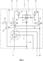
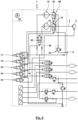
- Fig. 1 shows a schematic of a commercial vehicle compressed air treatment device 1 for a commercial vehicle known from the prior art.
- Compressed air from a compressor 2 is supplied to the commercial vehicle compressed air treatment device 1 via an inlet line 3.
- the inlet line 3 is connected to a pressure control valve 4.
- the pressure control valve 4 is designed as a pneumatically switchable 3/2-way valve.
- the inlet line 3 is connected to a vent connection 6 via the pressure control valve 4, so that the compressor 2 delivers compressed air to the environment, or to an inlet line 7.
- the inlet line 7 is connected to a central line 10, which feeds a compressed air system, via a drying unit 8 with a downstream check valve 9.
- the central line 10 supplies different consumer circuits via circuit protection valves.
- the inlet line 7 branches into partial inlet lines 7a, 7b to form two parallel line branches 11, 12, which are rejoined via a double check valve 13 arranged upstream adjacent to the check valve 9. Parallel to the double check valve 13, the two Line branches 11 are short-circuited via a throttle 14.
- An air drying cartridge 15, 16 is located in each of the line branches 11, 12.
- a pneumatically controlled 3/2-way valve 17, 18 is arranged upstream of the air drying cartridges 15, 16.
- the 3/2-way valves 17, 18 are actuated by the same control pressure, but have reversed switching positions as follows: In the Fig. 1 In the active switching position without applied control pressure, the 3/2-way valve 17 connects the partial inlet line 7a to the air drying cartridge 15, while the 3/2-way valve 18 connects the air drying cartridge 16 to the vent port 6a or one of the vent ports. If, however, the control port of the 3/2-way valves 17, 18 is pneumatically actuated, thereby switching the 3/2-way valves 17, 18, the 3/2-way valve 17 connects the air drying cartridge 15 on the inlet side to the vent port 6a, while the inlet port of the air drying cartridge 16 is connected to the partial inlet line 7 via the 3/2-way valve 18.
- Fig. 1 The problem with the embodiment known from the prior art according to Fig. 1 It may be that the partial volume flow used for regeneration via the throttle 14 cannot be regulated. Rather, it is predetermined by the cross-section of the throttle 14. This has the particular disadvantage that when the compressor 2 is operating at idle speed, the ratio of the partial air flow used for regeneration to the partial air flow supplied to the central line 10 is relatively large, whereas increasing the speed of the compressor 2 changes the proportion of the aforementioned partial air flows without any separate control options being available.
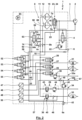
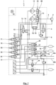
- the inlet line 3 is initially connected in a conventional manner to the vent connection 6 via a safety valve 22.
- the inlet line 3 branches via a valve 23, here a 5/2-way valve 24, into the two line branches 11, 12 with the air drying cartridges 15, 16.
- Two connections of the 5/2-way valve 24 are connected to the inlets of the air drying cartridges 15, 16, while two connections are connected to the vent connection 6 and a further connection is connected to the inlet line 3.
- the valve 23 for the illustrated embodiment is pneumatically controlled via a control line 25.
- consumer circuits 31, 32, 33, 34, 35, 36, 37, 38, 39, 40 are supplied via circuit protection valves 26, 27, 28, 29, 30.
- 32, 33, 34, 35 Consumer circuit 31 is a service brake circuit I with an upstream reservoir 36.
- Consumer circuit 32 is a service brake circuit II with an upstream reservoir 37.
- Consumer circuit 33 is a trailer brake circuit, whereby a partial consumer circuit 33a can be responsible for the trailer brake, while a parallel partial consumer circuit 33b is responsible for the spring-loaded brake.
- Consumer circuit 34 is used to supply auxiliary consumers.
- Consumer circuit 35 is formed with an air suspension system, for which purpose a reservoir 38 is provided.
- the circuit protection valves 26-30 serve in a manner known per se, in particular, to specify the filling sequence, to protect the pressure, and to enable cross-feeding of a consumer circuit from another consumer circuit during normal operation or in the event of a defect, preferably from a reservoir of the other consumer circuit.
- the circuit protection valves 26-28 are pneumatically pilot-operated overflow valves, in which the opening pressure of the overflow valve can be reduced by means of pneumatic control, or the function of the overflow valve can be bypassed by a through position. While the circuit protection valves 26, 27 are directly connected to the containers 36, 37, a pressure relief valve 39 is arranged downstream of the circuit protection valve 28.
- the output connection of the pressure relief valve 39 branches to the partial consumer circuits 33a, 33b, with a further check valve 40 opening in the direction of the partial consumer circuit 33b being provided in the partial consumer circuit 33b. Downstream of this check valve 40, the partial consumer circuit 33b is connected via a safety valve 41 to a vent connection 6a with an upstream check valve 42.
- the circuit protection valve 29 is designed with a series connection of an overflow valve 43 and a pressure relief valve 44.
- the circuit protection valve 30 is designed with an overflow valve 45 with a downstream check valve 46.
- Pressure sensors 47-50 measure the pressures in the consumer circuits 31, 32, 33a, and 35.
- the commercial vehicle compressed air treatment system 1 has a control unit 51 with suitable control logic to perform the control functions explained below.
- the pressure signals detected by the pressure sensors 47-50 are fed to the control unit 51 for evaluation.
- the control unit 51 controls for the Fig. 2
- the embodiment shown comprises four solenoid valves 52-55.
- the solenoid valves 52-55 are designed here as 3/2-way valves. Via a feed line 56 branching off from the central line 10, one connection of each of the solenoid valves 52-55 is supplied with compressed air. Another connection of the solenoid valves 52-55 is each connected to a vent line 57. Finally, the solenoid valves 52-55 each have a connection which is connected to a control line 58-60, 25.
- the control line 58 is connected on the one hand to a control connection of the compressor 2.
- control line 58 is connected to a control connection of the pressure regulator 4, which connects the inlet line 3 to the vent 6 for the pressurized control connection.
- the control line 59 is initially connected to the control ports of the circuit protection valves 26, 27, so that when the control port is pressurized, the opening pressures of the overflow valves are reduced or the overflow function is bypassed.
- the control line 60 is connected to the control port of the circuit protection valve 28.
- the control line 25 is connected to the control port of valve 23.
- a regeneration line 62 branches off from the central line 10 or the feed line 56, in which a throttle 14 is arranged and which leads to a regeneration valve 63.
- the regeneration valve 63 can be directly electrically controlled by the control unit 51.
- the regeneration valve 63 is pneumatically controlled, for which purpose the control connection of the regeneration valve 63 is connected to the control line 59.
- the regeneration valve 63 is designed as a 2/2-way valve, which assumes a blocking position without pneumatic pressure on the control line 59, while assuming a flow-through position when the control line 59 is pressurized.
- the operation of the compressed air processing device is, for example, as follows.
- the first step is Fig. 2 In the inactive switching position of the valve 23, a supply operation takes place in the line branch 11.
- the line branch 12 is not involved in this. Rather, the air drying cartridge 16 is connected to the vent connection 6 via the valve 23.
- the return of dried compressed air from the central line 10 is prevented on the one hand by the check valve 9b.
- the regeneration valve 63 is initially in a blocking position, so that no backflow of dried compressed air occurs via the regeneration lines 62, 64a.
- the regeneration valve 63 can be closed by the control unit 51, which can occur independently of any further supply operation in line branch 11.
- the used regeneration air can originate directly from line branch 11 and thus be returned to the commercial vehicle compressed air treatment device 1 without reaching the compressed air system 67. It is also possible for the regeneration air to be taken from a container in the compressed air system 67, for example, at least one of the containers 36, 37 of the service brake circuits.
- the compressed air delivery of the compressor 2 may be reduced or deactivated via the control line 58. It is also possible for the compressor 2 to discharge into the environment when the pressure regulator 4 is open. In this case, it may even be possible for regeneration air from one of the containers 36, 37 to flow through both air drying cartridges 15, 16 for regeneration purposes and to be supplied to connection 6 for the purpose of regeneration, with the regeneration valve 63 open and both check valves 65a, 65b open. It is also possible for several shorter regeneration phases to be carried out in the other line branch during supply operation via line branch 11, or for a regeneration phase to be temporarily interrupted.
- a change to a supply operation via line branch 12 takes place. This change is accomplished by switching the valve 23 by pneumatically venting the control line 25 with the solenoid valve 55. Also during supply operation via line branch 12, a regeneration of the air drying cartridge 15 in line branch 11 can be started and ended independently in a manner analogous to the manner described above by controlling the regeneration valve 63, wherein in this case the check valve 65b is flowed through by regeneration air.
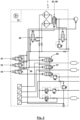
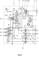
- the solenoid valve 55 was exclusively responsible for the pneumatic control of the valve 23, can be used with an otherwise essentially corresponding design according to Fig. 3 the solenoid valve 55 is omitted.
- the control line 59 is connected to the control connections of the circuit protection valves 26, 27 and the control connection of the regeneration valve 63, as is also the case for Fig. 2 was the case.
- the control line 59 is also connected to the control connection of the valve 23.
- the valve 23 is designed in this case as a so-called "bistable" valve 68. Such a bistable valve remains in a switching position once it has been assumed without pneumatic control and only leaves this position upon renewed, corresponding pneumatic control.
- the bistable valve 68 can, in contrast to the illustrated embodiment, be directly electrically controlled. Also possible is the pneumatic design of the bistable valve with a control connection, as is the case, for example, in DE 10 2008 038 437 A1 with a kind of "ballpoint pen mechanism" for which a switching position is held by applying pressure, while the switching position can be changed by briefly relieving pressure and re-pressurizing the control line 59.
- the aforementioned operating positions thus enable, in principle, independent of one another, the performance of a load operation in one of the air drying cartridges 15, 16, the performance of a regeneration operation of one of the air drying cartridges 15, 16, a simultaneous load operation of the air drying cartridges 15, 16 and/or a simultaneous regeneration operation of the air drying cartridges 15, 16.
Landscapes
- Engineering & Computer Science (AREA)
- Chemical & Material Sciences (AREA)
- Analytical Chemistry (AREA)
- General Chemical & Material Sciences (AREA)
- Oil, Petroleum & Natural Gas (AREA)
- Chemical Kinetics & Catalysis (AREA)
- Transportation (AREA)
- Mechanical Engineering (AREA)
- Drying Of Gases (AREA)
- Valves And Accessory Devices For Braking Systems (AREA)
Priority Applications (1)
| Application Number | Priority Date | Filing Date | Title |
|---|---|---|---|
| PL11171179.2T PL2407231T5 (pl) | 2010-07-14 | 2011-06-23 | Urządzenie do uzdatniania sprężonego powietrza w pojazdach użytkowych |
Applications Claiming Priority (1)
| Application Number | Priority Date | Filing Date | Title |
|---|---|---|---|
| DE102010031306.8A DE102010031306B4 (de) | 2010-07-14 | 2010-07-14 | Druckluftaufbereitungseinrichtung mit zwei Lufttrocknungskartuschen |
Publications (3)
| Publication Number | Publication Date |
|---|---|
| EP2407231A1 EP2407231A1 (de) | 2012-01-18 |
| EP2407231B1 EP2407231B1 (de) | 2017-11-01 |
| EP2407231B2 true EP2407231B2 (de) | 2025-06-25 |
Family
ID=44545484
Family Applications (1)
| Application Number | Title | Priority Date | Filing Date |
|---|---|---|---|
| EP11171179.2A Active EP2407231B2 (de) | 2010-07-14 | 2011-06-23 | Nutzfahrzeug-Druckluftaufbereitungseinrichtung |
Country Status (4)
| Country | Link |
|---|---|
| US (1) | US8628602B2 (pl) |
| EP (1) | EP2407231B2 (pl) |
| DE (1) | DE102010031306B4 (pl) |
| PL (1) | PL2407231T5 (pl) |
Families Citing this family (32)
| Publication number | Priority date | Publication date | Assignee | Title |
|---|---|---|---|---|
| DE102010038064B4 (de) | 2010-10-08 | 2013-02-21 | Haldex Brake Products Gmbh | Lufttrocknungskartusche |
| US8585809B2 (en) * | 2011-08-11 | 2013-11-19 | Bendix Commercial Vehicle Systems Llc | Air dryer cartridge |
| DE102012007342A1 (de) * | 2011-12-23 | 2013-06-27 | Wabco Gmbh | Druckluftversorgungsanlage, Druckluftversorgungssystem und Fahrzeug, insbesondere PKW mit einer Druckluftversorgungsanlage |
| DE102012005308B4 (de) | 2011-12-23 | 2022-03-17 | Wabco Gmbh | Druckluftversorgungsanlage, Druckluftversorgungssystem und Fahrzeug, insbesondere PKW, mit einer Druckluftversorgungsanlage |
| DE102012007028A1 (de) | 2012-04-05 | 2013-10-10 | Knorr-Bremse Systeme für Schienenfahrzeuge GmbH | Lufttrocknungseinrichtung für ein Schienenfahrzeug |
| EP2789512B2 (de) * | 2013-04-12 | 2021-08-25 | Haldex Brake Products GmbH | Druckluftaufbereitungseinrichtung für ein Nutzfahrzeug |
| DE102013011785A1 (de) * | 2013-07-15 | 2015-01-15 | Wabco Gmbh | Luftbeschaffungsvorrichtung für ein Druckluftsystem eines Fahrzeugs und derartiges Druckluftsystem |
| DE102013109476A1 (de) * | 2013-08-30 | 2015-03-05 | Knorr-Bremse Systeme für Schienenfahrzeuge GmbH | Verfahren und Einrichtung zur Regeneration eines Zweikammer-Lufttrockners |
| US9375679B2 (en) | 2013-08-30 | 2016-06-28 | Haldex Brake Products Corporation | Air dryer assembly with manifold system |
| DE102014202273A1 (de) * | 2014-02-07 | 2015-08-13 | Siemens Aktiengesellschaft | Anordnung und Verfahren zum Trocknen von Luft sowie Fahrzeug mit einer derartigen Anordnung |
| US9266515B2 (en) * | 2014-03-05 | 2016-02-23 | Bendix Commercial Vehicle Systems Llc | Air dryer purge controller and method |
| DE102014009991A1 (de) * | 2014-07-04 | 2016-01-07 | Knorr-Bremse Systeme für Nutzfahrzeuge GmbH | Verfahren und Vorrichtung zur Fehlererkennung in Druckluftsystemen |
| DE102014014274A1 (de) | 2014-09-26 | 2016-03-31 | Wabco Gmbh | Verfahren zum Betrieb eines Druckluftsystems eines Fahrzeugs |
| US10006365B2 (en) | 2015-06-30 | 2018-06-26 | General Electric Company | Air supply and conditioning system for a gas turbine |
| DE102015012494A1 (de) * | 2015-09-24 | 2017-03-30 | Wabco Europe Bvba | Trocknungseinrichtung einer Druckluftversorgungsanlage |
| DE102015219613A1 (de) * | 2015-10-09 | 2017-04-13 | Continental Teves Ag & Co. Ohg | Integrierte Luftversorgungseinheit mit Lufttrockner und Luftfedersystem, sowie Steuerung einer Luftversorgungseinheit |
| BE1023962B1 (nl) * | 2016-02-24 | 2017-09-26 | Atlas Copco Airpower,Naamloze Vennootschap | Werkwijze voor het regelen van de regeneratietijd van een adsorptiedroger en adsorptiedroger die zulke werkwijze toepast. |
| DE102016003311A1 (de) * | 2016-03-17 | 2017-09-21 | Wabco Gmbh | Trocknungseinrichtung einer Druckluftversorgungsanlage |
| EP3402586B1 (en) | 2016-03-23 | 2021-06-30 | New York Air Brake LLC | Adsorption drying unit and method of operating the same |
| BE1024244B9 (nl) * | 2016-04-08 | 2018-02-05 | Atlas Copco Airpower Nv | Een droger voor het drogen van persgas en werkwijze voor het regenereren van een droogmateriaal vervat in de droger. |
| CN107650901A (zh) * | 2017-10-09 | 2018-02-02 | 南京金龙客车制造有限公司 | 一种干燥器反吹装置及其工作方法 |
| DE102017124383A1 (de) * | 2017-10-19 | 2019-04-25 | Knorr-Bremse Systeme für Nutzfahrzeuge GmbH | Luftaufbereitungseinrichtung für Kraftfahrzeuge |
| SE541329C2 (en) * | 2017-11-09 | 2019-07-09 | Scania Cv Ab | A method for controlling an air processing system |
| DE102017129908A1 (de) | 2017-12-14 | 2019-06-19 | Knorr-Bremse Systeme für Nutzfahrzeuge GmbH | Anordnung für ein Nutzfahrzeug |
| CN108404614B (zh) * | 2018-04-11 | 2021-05-28 | 珠海市思卡净化技术有限公司 | 一种互动切换型压缩空气净化装置 |
| DE102018215300A1 (de) * | 2018-09-07 | 2020-03-12 | Knorr-Bremse Systeme für Nutzfahrzeuge GmbH | Pneumatisches Stellglied, Abluftsystem, Gehäuse mit Abluftsystem, pneumatischer Aktuator |
| CN113766963B (zh) * | 2019-02-25 | 2025-01-14 | 纳博特斯克汽车零部件有限公司 | 空气供给系统、空气供给系统的控制方法及空气供给系统的控制程序 |
| US11892192B1 (en) * | 2019-08-22 | 2024-02-06 | Transaera, Inc. | Air conditioning system with multiple energy storage sub-systems |
| US11874018B1 (en) | 2020-11-04 | 2024-01-16 | Transaera, Inc. | Cooling and dehumidifcation system |
| EP4265923A1 (en) * | 2020-12-18 | 2023-10-25 | Semyungtech Co., Ltd. | Compressed air processing system for commercial vehicle |
| DE102023123727A1 (de) * | 2023-09-04 | 2025-03-06 | Deere & Company | Pneumatische Versorgungseinrichtung für einen landwirtschaftlichen Traktor |
| EP4530141A1 (en) * | 2023-09-26 | 2025-04-02 | ZF CV Systems Europe BV | Twin chamber air dryer and electropneumatic system for a commercial vehicle |
Citations (2)
| Publication number | Priority date | Publication date | Assignee | Title |
|---|---|---|---|---|
| DE3533893A1 (de) † | 1985-09-23 | 1987-03-26 | Knorr Bremse Ag | Zweikammer-lufttrocknungsanlage, insbesondere fuer die druckluftversorgung der bremsanlagen von fahrzeugen |
| WO2011134575A2 (de) † | 2010-04-30 | 2011-11-03 | Wabco Gmbh | Druckluftaufbereitungseinrichtung, druckluftversorgungssystem mit einer druckluftaufbereitungseinrichtung und aufbereitungsmodul hierfür sowie verfahren zum betrieb einer druckluftaufbereitungseinrichtung, steuermodul und fahrzeug mit einer druckluftaufbereitungseinrichtung |
Family Cites Families (29)
| Publication number | Priority date | Publication date | Assignee | Title |
|---|---|---|---|---|
| FR690831A (fr) * | 1929-08-03 | 1930-09-26 | Silica Gel Corp | Dispositif pour le séchage de l'air des freins à air |
| NL62548C (pl) * | 1944-03-09 | |||
| US4197095A (en) * | 1978-08-31 | 1980-04-08 | Pall Corporation | Heatless adsorbent fractionators with microprocessor cycle control and process |
| DE3216815A1 (de) | 1982-05-05 | 1983-11-10 | Knorr-Bremse GmbH, 8000 München | Steuereinrichtung zur regenerierung eines lufttrockners fuer eine pneumatische anlage, insbesondere einer fahrzeugbremsanlage |
| DE3244414A1 (de) * | 1982-12-01 | 1984-06-07 | Robert Bosch Gmbh, 7000 Stuttgart | Vorrichtung zum trocknen von druckluft |
| DE3514473A1 (de) | 1985-04-22 | 1986-10-23 | Knorr-Bremse AG, 8000 München | Vorrichtung zum trocknen von druckluft |
| US4605425A (en) * | 1985-05-06 | 1986-08-12 | Pall Corporation | Heaterless dryer having variable cycle |
| US4718020A (en) * | 1985-05-30 | 1988-01-05 | Pall Corporation | Fault recovery procedure for heat-reactivated dryer |
| DE3525083A1 (de) * | 1985-07-13 | 1987-01-22 | Bosch Gmbh Robert | Vorrichtung zum trocknen von druckluft |
| JPS63130118A (ja) * | 1986-11-21 | 1988-06-02 | Nippon Air Brake Co Ltd | 2筒式除湿装置の制御方法 |
| US4941894A (en) * | 1988-04-12 | 1990-07-17 | Hankison Division Of Hansen, Inc. | Gas drying or fractioning apparatus and method |
| US5103576A (en) | 1989-01-26 | 1992-04-14 | Allied Signal Inc. | Charge/purge control system for air dryer with humidity control |
| US5685896A (en) | 1996-02-06 | 1997-11-11 | Westinghouse Air Brake Company | Linear choke shuttle/orifice check valve mechanism for a twin tower air dryer |
| DE19620851C2 (de) | 1996-05-23 | 1999-12-09 | Knorr Bremse Systeme | Luftaufbereitungsanordnung für Druckluft, insbesondere für pneumatische Bremsanlagen von Kraftfahrzeugen |
| US5901464A (en) | 1997-11-26 | 1999-05-11 | Westinghouse Air Brake Company | E-1 twin tower air dryer for an air compressor unit |
| US5901459A (en) | 1997-11-26 | 1999-05-11 | Westinghouse Air Brake Company | Shuttle mechanism for twin tower air dryer system |
| US5961698A (en) | 1998-02-02 | 1999-10-05 | Westinghouse Air Brake Company | Twin tower air dryer |
| US6014820A (en) | 1998-02-02 | 2000-01-18 | Westinghouse Air Brake Company | Shuttle valve for twin tower air dryer |
| GB0113205D0 (en) | 2001-05-31 | 2001-07-25 | Wabco Automotive Uk Ltd | Regeneration of air dryer |
| DE10314642B3 (de) * | 2003-04-01 | 2004-11-04 | Haldex Brake Products Gmbh | Druckluftaufbereitungsgerät |
| BRPI0410766A (pt) | 2003-05-19 | 2006-06-27 | Wabco Automotive Uk Ltd | cartucho de secador de ar |
| BRPI0411730A (pt) | 2003-06-25 | 2006-08-08 | Wabco Automotive Uk | cartucho secador a ar |
| DE10333610B4 (de) * | 2003-07-24 | 2005-09-15 | Haldex Brake Products Gmbh | Druckluftaufbereitungseinrichtung für Kraftfahrzeug-Druckluftanlagen |
| DE10338162B3 (de) | 2003-08-20 | 2005-06-02 | Haldex Brake Products Gmbh | Verfahren zum Betreiben einer Druckluftbeschaffungsanlage eines Kraftfahrzeuges sowie Druckluftaufbereitungseinrichtung |
| US7115152B2 (en) * | 2004-01-12 | 2006-10-03 | Friday David K | Four bed regenerable filter system |
| DE102004059508C5 (de) | 2004-12-10 | 2008-07-03 | Haldex Brake Products Gmbh | Verfahren zum Reinigen von Druckluft an Druckluftbeschaffungsanlagen von Kraftfahrzeugen sowie Kartusche hierfür |
| ITTO20070237A1 (it) * | 2007-04-03 | 2008-10-04 | Faiveley Transport Italia Spa | Gruppo di essiccazione ad adsorbimento con gestione ottimizzata della portata e/o della fase di rigenerazione e impianto di trattamento aria comprendente un tale gruppo |
| DE102008006860A1 (de) | 2008-01-31 | 2009-08-06 | Haldex Brake Products Gmbh | Kraftfahrzeug mit einer von einem Kompressor versorgten Druckluftanlage und Verfahren zur Steuerung des Luftstroms in einer Druckluftanlage |
| DE102008038437A1 (de) | 2008-08-20 | 2010-02-25 | Knorr-Bremse Systeme für Nutzfahrzeuge GmbH | Bistabiles Ventil und Verfahren zum Betätigen eines Feststellbremssystems mit einem bistabilen Ventil |
-
2010
- 2010-07-14 DE DE102010031306.8A patent/DE102010031306B4/de not_active Withdrawn - After Issue
-
2011
- 2011-06-23 EP EP11171179.2A patent/EP2407231B2/de active Active
- 2011-06-23 PL PL11171179.2T patent/PL2407231T5/pl unknown
- 2011-07-14 US US13/182,984 patent/US8628602B2/en active Active
Patent Citations (2)
| Publication number | Priority date | Publication date | Assignee | Title |
|---|---|---|---|---|
| DE3533893A1 (de) † | 1985-09-23 | 1987-03-26 | Knorr Bremse Ag | Zweikammer-lufttrocknungsanlage, insbesondere fuer die druckluftversorgung der bremsanlagen von fahrzeugen |
| WO2011134575A2 (de) † | 2010-04-30 | 2011-11-03 | Wabco Gmbh | Druckluftaufbereitungseinrichtung, druckluftversorgungssystem mit einer druckluftaufbereitungseinrichtung und aufbereitungsmodul hierfür sowie verfahren zum betrieb einer druckluftaufbereitungseinrichtung, steuermodul und fahrzeug mit einer druckluftaufbereitungseinrichtung |
Also Published As
| Publication number | Publication date |
|---|---|
| DE102010031306A1 (de) | 2012-01-19 |
| EP2407231B1 (de) | 2017-11-01 |
| PL2407231T3 (pl) | 2018-04-30 |
| PL2407231T5 (pl) | 2025-11-12 |
| DE102010031306B4 (de) | 2014-11-27 |
| US8628602B2 (en) | 2014-01-14 |
| EP2407231A1 (de) | 2012-01-18 |
| US20120031273A1 (en) | 2012-02-09 |
Similar Documents
| Publication | Publication Date | Title |
|---|---|---|
| EP2407231B2 (de) | Nutzfahrzeug-Druckluftaufbereitungseinrichtung | |
| EP2582560B2 (de) | Einrichtung, verfahren und system zur druckluftsteuerung und druckluftversorgung | |
| EP2829744B1 (de) | Luftbeschaffungsvorrichtung für ein Druckluftsystem eines Fahrzeugs und derartiges Druckluftsystem | |
| EP0808756B1 (de) | Luftaufbereitungsanordnung für Druckluft, insbesondere für pneumatische Bremsanlagen von Kraftfahrzeugen | |
| EP2289610B1 (de) | Verfahren zum Regenerieren einer Druckluftversorgungseinrichtung, Steuereinrichtung und Druckluftversorgungseinrichtung | |
| DE102012106549B4 (de) | Druckluftaufbereitungseinrichtung mit Reifenfüllanschluss | |
| DE19515895A1 (de) | Druckluft-Versorgungseinrichtung für Fahrzeug-Druckluftanlagen sowie Verfahren zum Steuern der Druckluft-Versorgungseinrichtung | |
| DE102010054063A1 (de) | Luftaufbereitungseinheit für ein Druckluftsystem eines Fahrzeuges | |
| EP2834116B1 (de) | Lufttrocknungseinrichtung für ein schienenfahrzeug | |
| DE102007013671A1 (de) | Druckluftversorgungseinrichtung für ein Nutzfahrzeug und Verfahren zum Betreiben einer Druckluftversorgungseinrichtung | |
| EP1508488B2 (de) | Verfahren zum Betreiben einer Druckluftbeschaffungsanlage eines Kraftfahrzeuges sowie Druckluftaufbereitungseinrichtung | |
| EP2686215B1 (de) | Lufttrockneradaptermodul, lufttrocknermodul und druckluftversorgungseinrichtung | |
| EP2566733B1 (de) | Vorrichtung zum steuern einer elektro-pneumatischen bremseinrichtung | |
| WO2015028533A1 (de) | Verfahren und einrichtung zur regeneration eines zweikammer-lufttrockners | |
| EP2675674B1 (de) | Druckluftversorgungseinrichtung für nutzfahrzeuge | |
| EP3247603A1 (de) | Vorrichtung und verfahren zum versorgen eines nutzfahrzeugs mit druckluft | |
| EP2117898B1 (de) | Ventileinrichtung für eine druckluftversorgungseinrichtung und druckluftversorgungsanlage | |
| DE102004038705B3 (de) | Druckluftanlage | |
| EP3590779B1 (de) | Druckluftaufbereitungseinrichtung und verfahren zum betreiben einer solchen | |
| EP2789512B2 (de) | Druckluftaufbereitungseinrichtung für ein Nutzfahrzeug | |
| DE102012102490C5 (de) | Druckluftaufbereitungseinrichtung für ein Nutzfahrzeug | |
| DE3813175A1 (de) | Bremsdruckregelvorrichtung |
Legal Events
| Date | Code | Title | Description |
|---|---|---|---|
| AK | Designated contracting states |
Kind code of ref document: A1 Designated state(s): AL AT BE BG CH CY CZ DE DK EE ES FI FR GB GR HR HU IE IS IT LI LT LU LV MC MK MT NL NO PL PT RO RS SE SI SK SM TR |
|
| AX | Request for extension of the european patent |
Extension state: BA ME |
|
| PUAI | Public reference made under article 153(3) epc to a published international application that has entered the european phase |
Free format text: ORIGINAL CODE: 0009012 |
|
| 17P | Request for examination filed |
Effective date: 20120215 |
|
| 17Q | First examination report despatched |
Effective date: 20141001 |
|
| RAP1 | Party data changed (applicant data changed or rights of an application transferred) |
Owner name: HALDEX BRAKE PRODUCTS AKTIEBOLAG |
|
| GRAP | Despatch of communication of intention to grant a patent |
Free format text: ORIGINAL CODE: EPIDOSNIGR1 |
|
| STAA | Information on the status of an ep patent application or granted ep patent |
Free format text: STATUS: GRANT OF PATENT IS INTENDED |
|
| INTG | Intention to grant announced |
Effective date: 20170626 |
|
| GRAS | Grant fee paid |
Free format text: ORIGINAL CODE: EPIDOSNIGR3 |
|
| GRAA | (expected) grant |
Free format text: ORIGINAL CODE: 0009210 |
|
| STAA | Information on the status of an ep patent application or granted ep patent |
Free format text: STATUS: THE PATENT HAS BEEN GRANTED |
|
| AK | Designated contracting states |
Kind code of ref document: B1 Designated state(s): AL AT BE BG CH CY CZ DE DK EE ES FI FR GB GR HR HU IE IS IT LI LT LU LV MC MK MT NL NO PL PT RO RS SE SI SK SM TR |
|
| REG | Reference to a national code |
Ref country code: GB Ref legal event code: FG4D Free format text: NOT ENGLISH |
|
| REG | Reference to a national code |
Ref country code: CH Ref legal event code: EP Ref country code: AT Ref legal event code: REF Ref document number: 941500 Country of ref document: AT Kind code of ref document: T Effective date: 20171115 |
|
| REG | Reference to a national code |
Ref country code: IE Ref legal event code: FG4D Free format text: LANGUAGE OF EP DOCUMENT: GERMAN |
|
| REG | Reference to a national code |
Ref country code: DE Ref legal event code: R096 Ref document number: 502011013217 Country of ref document: DE |
|
| REG | Reference to a national code |
Ref country code: SE Ref legal event code: TRGR |
|
| REG | Reference to a national code |
Ref country code: NL Ref legal event code: MP Effective date: 20171101 |
|
| REG | Reference to a national code |
Ref country code: LT Ref legal event code: MG4D |
|
| PG25 | Lapsed in a contracting state [announced via postgrant information from national office to epo] |
Ref country code: LT Free format text: LAPSE BECAUSE OF FAILURE TO SUBMIT A TRANSLATION OF THE DESCRIPTION OR TO PAY THE FEE WITHIN THE PRESCRIBED TIME-LIMIT Effective date: 20171101 Ref country code: NL Free format text: LAPSE BECAUSE OF FAILURE TO SUBMIT A TRANSLATION OF THE DESCRIPTION OR TO PAY THE FEE WITHIN THE PRESCRIBED TIME-LIMIT Effective date: 20171101 Ref country code: ES Free format text: LAPSE BECAUSE OF FAILURE TO SUBMIT A TRANSLATION OF THE DESCRIPTION OR TO PAY THE FEE WITHIN THE PRESCRIBED TIME-LIMIT Effective date: 20171101 Ref country code: NO Free format text: LAPSE BECAUSE OF FAILURE TO SUBMIT A TRANSLATION OF THE DESCRIPTION OR TO PAY THE FEE WITHIN THE PRESCRIBED TIME-LIMIT Effective date: 20180201 Ref country code: FI Free format text: LAPSE BECAUSE OF FAILURE TO SUBMIT A TRANSLATION OF THE DESCRIPTION OR TO PAY THE FEE WITHIN THE PRESCRIBED TIME-LIMIT Effective date: 20171101 |
|
| PG25 | Lapsed in a contracting state [announced via postgrant information from national office to epo] |
Ref country code: RS Free format text: LAPSE BECAUSE OF FAILURE TO SUBMIT A TRANSLATION OF THE DESCRIPTION OR TO PAY THE FEE WITHIN THE PRESCRIBED TIME-LIMIT Effective date: 20171101 Ref country code: LV Free format text: LAPSE BECAUSE OF FAILURE TO SUBMIT A TRANSLATION OF THE DESCRIPTION OR TO PAY THE FEE WITHIN THE PRESCRIBED TIME-LIMIT Effective date: 20171101 Ref country code: IS Free format text: LAPSE BECAUSE OF FAILURE TO SUBMIT A TRANSLATION OF THE DESCRIPTION OR TO PAY THE FEE WITHIN THE PRESCRIBED TIME-LIMIT Effective date: 20180301 Ref country code: BG Free format text: LAPSE BECAUSE OF FAILURE TO SUBMIT A TRANSLATION OF THE DESCRIPTION OR TO PAY THE FEE WITHIN THE PRESCRIBED TIME-LIMIT Effective date: 20180201 Ref country code: GR Free format text: LAPSE BECAUSE OF FAILURE TO SUBMIT A TRANSLATION OF THE DESCRIPTION OR TO PAY THE FEE WITHIN THE PRESCRIBED TIME-LIMIT Effective date: 20180202 Ref country code: HR Free format text: LAPSE BECAUSE OF FAILURE TO SUBMIT A TRANSLATION OF THE DESCRIPTION OR TO PAY THE FEE WITHIN THE PRESCRIBED TIME-LIMIT Effective date: 20171101 |
|
| REG | Reference to a national code |
Ref country code: FR Ref legal event code: PLFP Year of fee payment: 8 |
|
| PG25 | Lapsed in a contracting state [announced via postgrant information from national office to epo] |
Ref country code: DK Free format text: LAPSE BECAUSE OF FAILURE TO SUBMIT A TRANSLATION OF THE DESCRIPTION OR TO PAY THE FEE WITHIN THE PRESCRIBED TIME-LIMIT Effective date: 20171101 Ref country code: SK Free format text: LAPSE BECAUSE OF FAILURE TO SUBMIT A TRANSLATION OF THE DESCRIPTION OR TO PAY THE FEE WITHIN THE PRESCRIBED TIME-LIMIT Effective date: 20171101 Ref country code: CZ Free format text: LAPSE BECAUSE OF FAILURE TO SUBMIT A TRANSLATION OF THE DESCRIPTION OR TO PAY THE FEE WITHIN THE PRESCRIBED TIME-LIMIT Effective date: 20171101 Ref country code: EE Free format text: LAPSE BECAUSE OF FAILURE TO SUBMIT A TRANSLATION OF THE DESCRIPTION OR TO PAY THE FEE WITHIN THE PRESCRIBED TIME-LIMIT Effective date: 20171101 Ref country code: CY Free format text: LAPSE BECAUSE OF FAILURE TO SUBMIT A TRANSLATION OF THE DESCRIPTION OR TO PAY THE FEE WITHIN THE PRESCRIBED TIME-LIMIT Effective date: 20171101 |
|
| REG | Reference to a national code |
Ref country code: DE Ref legal event code: R026 Ref document number: 502011013217 Country of ref document: DE |
|
| PLBI | Opposition filed |
Free format text: ORIGINAL CODE: 0009260 |
|
| PLAX | Notice of opposition and request to file observation + time limit sent |
Free format text: ORIGINAL CODE: EPIDOSNOBS2 |
|
| PG25 | Lapsed in a contracting state [announced via postgrant information from national office to epo] |
Ref country code: RO Free format text: LAPSE BECAUSE OF FAILURE TO SUBMIT A TRANSLATION OF THE DESCRIPTION OR TO PAY THE FEE WITHIN THE PRESCRIBED TIME-LIMIT Effective date: 20171101 Ref country code: IT Free format text: LAPSE BECAUSE OF FAILURE TO SUBMIT A TRANSLATION OF THE DESCRIPTION OR TO PAY THE FEE WITHIN THE PRESCRIBED TIME-LIMIT Effective date: 20171101 Ref country code: SM Free format text: LAPSE BECAUSE OF FAILURE TO SUBMIT A TRANSLATION OF THE DESCRIPTION OR TO PAY THE FEE WITHIN THE PRESCRIBED TIME-LIMIT Effective date: 20171101 |
|
| 26 | Opposition filed |
Opponent name: KNORR-BREMSE SYSTEME FUER NUTZFAHRZEUGE GMBH Effective date: 20180731 |
|
| PG25 | Lapsed in a contracting state [announced via postgrant information from national office to epo] |
Ref country code: MT Free format text: LAPSE BECAUSE OF FAILURE TO SUBMIT A TRANSLATION OF THE DESCRIPTION OR TO PAY THE FEE WITHIN THE PRESCRIBED TIME-LIMIT Effective date: 20171101 |
|
| PLBB | Reply of patent proprietor to notice(s) of opposition received |
Free format text: ORIGINAL CODE: EPIDOSNOBS3 |
|
| PG25 | Lapsed in a contracting state [announced via postgrant information from national office to epo] |
Ref country code: SI Free format text: LAPSE BECAUSE OF FAILURE TO SUBMIT A TRANSLATION OF THE DESCRIPTION OR TO PAY THE FEE WITHIN THE PRESCRIBED TIME-LIMIT Effective date: 20171101 |
|
| REG | Reference to a national code |
Ref country code: CH Ref legal event code: PL |
|
| GBPC | Gb: european patent ceased through non-payment of renewal fee |
Effective date: 20180623 |
|
| REG | Reference to a national code |
Ref country code: BE Ref legal event code: MM Effective date: 20180630 |
|
| REG | Reference to a national code |
Ref country code: IE Ref legal event code: MM4A |
|
| PG25 | Lapsed in a contracting state [announced via postgrant information from national office to epo] |
Ref country code: LU Free format text: LAPSE BECAUSE OF NON-PAYMENT OF DUE FEES Effective date: 20180623 Ref country code: MC Free format text: LAPSE BECAUSE OF FAILURE TO SUBMIT A TRANSLATION OF THE DESCRIPTION OR TO PAY THE FEE WITHIN THE PRESCRIBED TIME-LIMIT Effective date: 20171101 |
|
| PG25 | Lapsed in a contracting state [announced via postgrant information from national office to epo] |
Ref country code: IE Free format text: LAPSE BECAUSE OF NON-PAYMENT OF DUE FEES Effective date: 20180623 Ref country code: GB Free format text: LAPSE BECAUSE OF NON-PAYMENT OF DUE FEES Effective date: 20180623 Ref country code: CH Free format text: LAPSE BECAUSE OF NON-PAYMENT OF DUE FEES Effective date: 20180630 Ref country code: LI Free format text: LAPSE BECAUSE OF NON-PAYMENT OF DUE FEES Effective date: 20180630 |
|
| PG25 | Lapsed in a contracting state [announced via postgrant information from national office to epo] |
Ref country code: BE Free format text: LAPSE BECAUSE OF NON-PAYMENT OF DUE FEES Effective date: 20180630 |
|
| REG | Reference to a national code |
Ref country code: AT Ref legal event code: MM01 Ref document number: 941500 Country of ref document: AT Kind code of ref document: T Effective date: 20180623 |
|
| PG25 | Lapsed in a contracting state [announced via postgrant information from national office to epo] |
Ref country code: AT Free format text: LAPSE BECAUSE OF NON-PAYMENT OF DUE FEES Effective date: 20180623 |
|
| PG25 | Lapsed in a contracting state [announced via postgrant information from national office to epo] |
Ref country code: TR Free format text: LAPSE BECAUSE OF FAILURE TO SUBMIT A TRANSLATION OF THE DESCRIPTION OR TO PAY THE FEE WITHIN THE PRESCRIBED TIME-LIMIT Effective date: 20171101 |
|
| APBM | Appeal reference recorded |
Free format text: ORIGINAL CODE: EPIDOSNREFNO |
|
| APBP | Date of receipt of notice of appeal recorded |
Free format text: ORIGINAL CODE: EPIDOSNNOA2O |
|
| APAH | Appeal reference modified |
Free format text: ORIGINAL CODE: EPIDOSCREFNO |
|
| APBM | Appeal reference recorded |
Free format text: ORIGINAL CODE: EPIDOSNREFNO |
|
| APBP | Date of receipt of notice of appeal recorded |
Free format text: ORIGINAL CODE: EPIDOSNNOA2O |
|
| APBQ | Date of receipt of statement of grounds of appeal recorded |
Free format text: ORIGINAL CODE: EPIDOSNNOA3O |
|
| PG25 | Lapsed in a contracting state [announced via postgrant information from national office to epo] |
Ref country code: HU Free format text: LAPSE BECAUSE OF FAILURE TO SUBMIT A TRANSLATION OF THE DESCRIPTION OR TO PAY THE FEE WITHIN THE PRESCRIBED TIME-LIMIT; INVALID AB INITIO Effective date: 20110623 Ref country code: PT Free format text: LAPSE BECAUSE OF FAILURE TO SUBMIT A TRANSLATION OF THE DESCRIPTION OR TO PAY THE FEE WITHIN THE PRESCRIBED TIME-LIMIT Effective date: 20171101 |
|
| APBQ | Date of receipt of statement of grounds of appeal recorded |
Free format text: ORIGINAL CODE: EPIDOSNNOA3O |
|
| PG25 | Lapsed in a contracting state [announced via postgrant information from national office to epo] |
Ref country code: MK Free format text: LAPSE BECAUSE OF NON-PAYMENT OF DUE FEES Effective date: 20171101 |
|
| PG25 | Lapsed in a contracting state [announced via postgrant information from national office to epo] |
Ref country code: AL Free format text: LAPSE BECAUSE OF FAILURE TO SUBMIT A TRANSLATION OF THE DESCRIPTION OR TO PAY THE FEE WITHIN THE PRESCRIBED TIME-LIMIT Effective date: 20171101 |
|
| APBU | Appeal procedure closed |
Free format text: ORIGINAL CODE: EPIDOSNNOA9O |
|
| PLAY | Examination report in opposition despatched + time limit |
Free format text: ORIGINAL CODE: EPIDOSNORE2 |
|
| PLBC | Reply to examination report in opposition received |
Free format text: ORIGINAL CODE: EPIDOSNORE3 |
|
| PLAY | Examination report in opposition despatched + time limit |
Free format text: ORIGINAL CODE: EPIDOSNORE2 |
|
| REG | Reference to a national code |
Ref country code: DE Ref legal event code: R082 Ref document number: 502011013217 Country of ref document: DE Representative=s name: MUELLER SCHUPFNER & PARTNER PATENT- UND RECHTS, DE |
|
| PLBC | Reply to examination report in opposition received |
Free format text: ORIGINAL CODE: EPIDOSNORE3 |
|
| REG | Reference to a national code |
Ref country code: DE Ref legal event code: R081 Ref document number: 502011013217 Country of ref document: DE Owner name: HALDEX AB, SE Free format text: FORMER OWNER: HALDEX BRAKE PRODUCTS AKTIEBOLAG, LANDSKRONA, SE |
|
| RAP2 | Party data changed (patent owner data changed or rights of a patent transferred) |
Owner name: HALDEX AKTIEBOLAG |
|
| REG | Reference to a national code |
Ref country code: CH Ref legal event code: PK Free format text: TITEL |
|
| PUAH | Patent maintained in amended form |
Free format text: ORIGINAL CODE: 0009272 |
|
| STAA | Information on the status of an ep patent application or granted ep patent |
Free format text: STATUS: PATENT MAINTAINED AS AMENDED |
|
| 27A | Patent maintained in amended form |
Effective date: 20250625 |
|
| AK | Designated contracting states |
Kind code of ref document: B2 Designated state(s): AL AT BE BG CH CY CZ DE DK EE ES FI FR GB GR HR HU IE IS IT LI LT LU LV MC MK MT NL NO PL PT RO RS SE SI SK SM TR |
|
| REG | Reference to a national code |
Ref country code: DE Ref legal event code: R102 Ref document number: 502011013217 Country of ref document: DE |
|
| PGFP | Annual fee paid to national office [announced via postgrant information from national office to epo] |
Ref country code: DE Payment date: 20250519 Year of fee payment: 15 Ref country code: PL Payment date: 20250612 Year of fee payment: 15 |
|
| PGFP | Annual fee paid to national office [announced via postgrant information from national office to epo] |
Ref country code: FR Payment date: 20250618 Year of fee payment: 15 |
|
| PGFP | Annual fee paid to national office [announced via postgrant information from national office to epo] |
Ref country code: SE Payment date: 20250618 Year of fee payment: 15 |
|
| REG | Reference to a national code |
Ref country code: SE Ref legal event code: RPEO |