EP2405955B1 - Blutbehandlungvorrichtung mit vorrichtung verbinden einer externen funktionseinrichtung mit einer anordnung, anordnung aufweisend eine solche vorrichtung und verfahren zum verbinden - Google Patents
Blutbehandlungvorrichtung mit vorrichtung verbinden einer externen funktionseinrichtung mit einer anordnung, anordnung aufweisend eine solche vorrichtung und verfahren zum verbinden Download PDFInfo
- Publication number
- EP2405955B1 EP2405955B1 EP10708928.6A EP10708928A EP2405955B1 EP 2405955 B1 EP2405955 B1 EP 2405955B1 EP 10708928 A EP10708928 A EP 10708928A EP 2405955 B1 EP2405955 B1 EP 2405955B1
- Authority
- EP
- European Patent Office
- Prior art keywords
- contact portion
- external functional
- contact
- arrangement
- contact section
- Prior art date
- Legal status (The legal status is an assumption and is not a legal conclusion. Google has not performed a legal analysis and makes no representation as to the accuracy of the status listed.)
- Active
Links
Images

Classifications
-
- A—HUMAN NECESSITIES
- A61—MEDICAL OR VETERINARY SCIENCE; HYGIENE
- A61M—DEVICES FOR INTRODUCING MEDIA INTO, OR ONTO, THE BODY; DEVICES FOR TRANSDUCING BODY MEDIA OR FOR TAKING MEDIA FROM THE BODY; DEVICES FOR PRODUCING OR ENDING SLEEP OR STUPOR
- A61M1/00—Suction or pumping devices for medical purposes; Devices for carrying-off, for treatment of, or for carrying-over, body-liquids; Drainage systems
- A61M1/36—Other treatment of blood in a by-pass of the natural circulatory system, e.g. temperature adaptation, irradiation ; Extra-corporeal blood circuits
- A61M1/3621—Extra-corporeal blood circuits
-
- A—HUMAN NECESSITIES
- A61—MEDICAL OR VETERINARY SCIENCE; HYGIENE
- A61M—DEVICES FOR INTRODUCING MEDIA INTO, OR ONTO, THE BODY; DEVICES FOR TRANSDUCING BODY MEDIA OR FOR TAKING MEDIA FROM THE BODY; DEVICES FOR PRODUCING OR ENDING SLEEP OR STUPOR
- A61M1/00—Suction or pumping devices for medical purposes; Devices for carrying-off, for treatment of, or for carrying-over, body-liquids; Drainage systems
- A61M1/14—Dialysis systems; Artificial kidneys; Blood oxygenators ; Reciprocating systems for treatment of body fluids, e.g. single needle systems for hemofiltration or pheresis
-
- A—HUMAN NECESSITIES
- A61—MEDICAL OR VETERINARY SCIENCE; HYGIENE
- A61M—DEVICES FOR INTRODUCING MEDIA INTO, OR ONTO, THE BODY; DEVICES FOR TRANSDUCING BODY MEDIA OR FOR TAKING MEDIA FROM THE BODY; DEVICES FOR PRODUCING OR ENDING SLEEP OR STUPOR
- A61M1/00—Suction or pumping devices for medical purposes; Devices for carrying-off, for treatment of, or for carrying-over, body-liquids; Drainage systems
- A61M1/36—Other treatment of blood in a by-pass of the natural circulatory system, e.g. temperature adaptation, irradiation ; Extra-corporeal blood circuits
- A61M1/3621—Extra-corporeal blood circuits
- A61M1/3622—Extra-corporeal blood circuits with a cassette forming partially or totally the blood circuit
-
- A—HUMAN NECESSITIES
- A61—MEDICAL OR VETERINARY SCIENCE; HYGIENE
- A61M—DEVICES FOR INTRODUCING MEDIA INTO, OR ONTO, THE BODY; DEVICES FOR TRANSDUCING BODY MEDIA OR FOR TAKING MEDIA FROM THE BODY; DEVICES FOR PRODUCING OR ENDING SLEEP OR STUPOR
- A61M1/00—Suction or pumping devices for medical purposes; Devices for carrying-off, for treatment of, or for carrying-over, body-liquids; Drainage systems
- A61M1/36—Other treatment of blood in a by-pass of the natural circulatory system, e.g. temperature adaptation, irradiation ; Extra-corporeal blood circuits
- A61M1/3621—Extra-corporeal blood circuits
- A61M1/3622—Extra-corporeal blood circuits with a cassette forming partially or totally the blood circuit
- A61M1/36222—Details related to the interface between cassette and machine
- A61M1/362227—Details related to the interface between cassette and machine the interface providing means for actuating on functional elements of the cassette, e.g. plungers
-
- A—HUMAN NECESSITIES
- A61—MEDICAL OR VETERINARY SCIENCE; HYGIENE
- A61M—DEVICES FOR INTRODUCING MEDIA INTO, OR ONTO, THE BODY; DEVICES FOR TRANSDUCING BODY MEDIA OR FOR TAKING MEDIA FROM THE BODY; DEVICES FOR PRODUCING OR ENDING SLEEP OR STUPOR
- A61M2205/00—General characteristics of the apparatus
- A61M2205/12—General characteristics of the apparatus with interchangeable cassettes forming partially or totally the fluid circuit
-
- A—HUMAN NECESSITIES
- A61—MEDICAL OR VETERINARY SCIENCE; HYGIENE
- A61M—DEVICES FOR INTRODUCING MEDIA INTO, OR ONTO, THE BODY; DEVICES FOR TRANSDUCING BODY MEDIA OR FOR TAKING MEDIA FROM THE BODY; DEVICES FOR PRODUCING OR ENDING SLEEP OR STUPOR
- A61M2205/00—General characteristics of the apparatus
- A61M2205/12—General characteristics of the apparatus with interchangeable cassettes forming partially or totally the fluid circuit
- A61M2205/127—General characteristics of the apparatus with interchangeable cassettes forming partially or totally the fluid circuit with provisions for heating or cooling
-
- Y—GENERAL TAGGING OF NEW TECHNOLOGICAL DEVELOPMENTS; GENERAL TAGGING OF CROSS-SECTIONAL TECHNOLOGIES SPANNING OVER SEVERAL SECTIONS OF THE IPC; TECHNICAL SUBJECTS COVERED BY FORMER USPC CROSS-REFERENCE ART COLLECTIONS [XRACs] AND DIGESTS
- Y10—TECHNICAL SUBJECTS COVERED BY FORMER USPC
- Y10T—TECHNICAL SUBJECTS COVERED BY FORMER US CLASSIFICATION
- Y10T29/00—Metal working
- Y10T29/49—Method of mechanical manufacture
- Y10T29/49826—Assembling or joining
-
- Y—GENERAL TAGGING OF NEW TECHNOLOGICAL DEVELOPMENTS; GENERAL TAGGING OF CROSS-SECTIONAL TECHNOLOGIES SPANNING OVER SEVERAL SECTIONS OF THE IPC; TECHNICAL SUBJECTS COVERED BY FORMER USPC CROSS-REFERENCE ART COLLECTIONS [XRACs] AND DIGESTS
- Y10—TECHNICAL SUBJECTS COVERED BY FORMER USPC
- Y10T—TECHNICAL SUBJECTS COVERED BY FORMER US CLASSIFICATION
- Y10T403/00—Joints and connections
- Y10T403/32—Articulated members
-
- Y—GENERAL TAGGING OF NEW TECHNOLOGICAL DEVELOPMENTS; GENERAL TAGGING OF CROSS-SECTIONAL TECHNOLOGIES SPANNING OVER SEVERAL SECTIONS OF THE IPC; TECHNICAL SUBJECTS COVERED BY FORMER USPC CROSS-REFERENCE ART COLLECTIONS [XRACs] AND DIGESTS
- Y10—TECHNICAL SUBJECTS COVERED BY FORMER USPC
- Y10T—TECHNICAL SUBJECTS COVERED BY FORMER US CLASSIFICATION
- Y10T403/00—Joints and connections
- Y10T403/32—Articulated members
- Y10T403/32254—Lockable at fixed position
-
- Y—GENERAL TAGGING OF NEW TECHNOLOGICAL DEVELOPMENTS; GENERAL TAGGING OF CROSS-SECTIONAL TECHNOLOGIES SPANNING OVER SEVERAL SECTIONS OF THE IPC; TECHNICAL SUBJECTS COVERED BY FORMER USPC CROSS-REFERENCE ART COLLECTIONS [XRACs] AND DIGESTS
- Y10—TECHNICAL SUBJECTS COVERED BY FORMER USPC
- Y10T—TECHNICAL SUBJECTS COVERED BY FORMER US CLASSIFICATION
- Y10T403/00—Joints and connections
- Y10T403/32—Articulated members
- Y10T403/32606—Pivoted
- Y10T403/32631—Universal ball and socket
-
- Y—GENERAL TAGGING OF NEW TECHNOLOGICAL DEVELOPMENTS; GENERAL TAGGING OF CROSS-SECTIONAL TECHNOLOGIES SPANNING OVER SEVERAL SECTIONS OF THE IPC; TECHNICAL SUBJECTS COVERED BY FORMER USPC CROSS-REFERENCE ART COLLECTIONS [XRACs] AND DIGESTS
- Y10—TECHNICAL SUBJECTS COVERED BY FORMER USPC
- Y10T—TECHNICAL SUBJECTS COVERED BY FORMER US CLASSIFICATION
- Y10T403/00—Joints and connections
- Y10T403/32—Articulated members
- Y10T403/32975—Rotatable
Definitions
- the present invention relates to a device for connecting at least one external functional device with an arrangement according to the preamble of claim 1. It further relates to a method for connecting at least one external functional device with an arrangement using the device according to the invention according to the preamble of claim 13, and a Arrangement according to claim 14, comprising a device according to the invention.
- a functional coupling of such external functional devices usually requires their correct positioning and / or fixation on or on the arrangement, so that arrangement-side sensors and actuators can interact with the external functional device without errors.
- the object of the present invention is to provide a further device for connecting at least one external functional device with an arrangement. Furthermore, a method for connecting at least one external functional device and an arrangement comprising such a device should be specified.
- the device according to the invention serves for connecting or for connecting, in particular for coupling, at least one external functional device with an arrangement and has at least one receiving device with at least one first contact section and at least one second contact section, between which the external functional device can be received.
- at least the first contact portion and / or the second contact portion is movably arranged, preferably stored.
- movable is preferably a self-tracking mobility or mobility of the movable contact portion to understand.
- movable may exclude mobility, such as merely pivoting about a suspension on a hinge, such as the known pivoting of a door.
- this meaning may alternatively be explicitly encompassed by the present invention in the context of the term "movable”.
- the first and / or the second contact portion may be provided such that they are arranged pendulum, preferably are stored, so can commute at least in the process of connecting in at least one direction.
- an "external functional device” may be a heat exchanger, a measuring device, a multifunctional disposable cassette, or the like.
- An external functional device contemplated by this invention may be suitable for conducting medical fluids, such as blood, substituate fluid, or the like.
- Such an external functional device may be, for example, a blood-carrying cassette. It can contain parts of extracorporeal blood circulation. In particular, it can be configured as a disposable cassette, as shown in the DE 10 2007 042 964 is described. The entire disclosure of which is incorporated herein by reference.
- the terms “may comprise,””maybe,” and the like are synonymous with the terms “preferred", “preferred,” and the like, as used herein and elsewhere ,
- the external functional device may preferably transmit, receive, or be in fluid communication with the device, energy, measurements, and / or mechanical motions and forces on the device. However, it can alternatively be held only by the arrangement and can not interact with it and / or signal communication and / or fluid connection.
- the external functional device to be accommodated or connected may have a cover on at least one surface.
- a cover may be a foil.
- the film may be provided for receiving sensors and / or actuators and / or lines and / or parts thereof.
- the film may have openings for receiving such components and / or such components may be integrated into the film and / or a film composite.
- An “arrangement” in the sense of the present invention is a medical device arrangement, such as a blood treatment device, for example a dialysis device, a hemodialysis device, a hemodiafiltration device or the like.
- bonding may refer to or include functional and / or mechanical bonding of the external functional device to the assembly.
- the term “docking” may refer to operatively and / or mechanically connecting the external functional device to a coupling partner on the side of the array having an interaction or signal communication or fluid connection between external functional device and coupled device state of the external functional device or include.
- a "coupling partner of the arrangement” may be, for example, a measuring device, such as a sensor. It can be configured as a fluid line and the like.
- a "receiving device” in the sense of the present invention is a device that is suitable for receiving at least one external functional device.
- recording may mean holding, encompassing, encompassing, covering the external functional device, and the like, as well as combinations thereof.
- the "first contact section" of the receiving device is preferably provided on the device according to the invention itself or on an arrangement. It can be mobile, e.g. in the vertical and / or horizontal or other direction - in each case based on the center of the earth - oscillating, be arranged within the device or the arrangement.
- the first contact section can take on different functions. For example, it can be used for aligning the external functional device, for latching it and / or for transmitting a pressing force to the external functional device as well as combinations of the aforementioned functions.
- the first contact portion may include or be connected to other means for assisting in compressing the external functional device and / or holding it, such as a crimping device and / or a locking device.
- the first contact section may be a "docking pad”, an “activator / sensor pad” ("AS pad” for short) or a machine interface.
- Coupled surface may, for example, designate at least a portion of an upper side of a carrier element and / or a support element and / or a measuring device or the like of the arrangement and / or the device.
- An "AS plate” may comprise actuators and / or sensors and / or lines for coupling to the external functional device or parts thereof.
- an interaction or signal communication may be established between the external functional device and a portion of the device or assembly.
- Actuators as used herein include, but are not limited to, mechanical and / or pneumatic and / or electrical components such as valves, actuators and / or regulators, actuators, plungers, and the like.
- Sensors as referred to herein include, but are not limited to, electrical, optical, acoustic, virtual and / or digital sensors, transducers and / or transducers, and the like.
- a sensor may have certain physical and / or chemical properties and / or a change thereof, such as an increase or decrease in an effect, a form, a texture and the like, such as temperature, pressure, humidity, optical signals, such as brightness and / or qualitatively or quantitatively detect an optical change of a composition, heat radiation, sound, flow rates, and / or the physical condition of its environment.
- Such sensors may be designed as passive sensors or active sensors.
- Conduits such as may be used in the present invention may include, but are not limited to, fluid conduits such as blood-carrying channels, substituate conduits, electrical leads, signal communication conduits such as fiber optic cables, and the like.
- the "second contact portion" of the receiving device may be configured as the first contact portion and preferably assume the same functions.
- the "second contact portion” may be a pressure plate. It can be flat, tiered, wavy or otherwise configured. It can contact punctiform or flat with the external functional device in contact. It may have a section which corresponds in its geometry to an extension of the external functional device to be coupled - in the coupled or in the non-coupled state. This may facilitate or facilitate their uptake and / or alignment.
- the second contact portion may be designed to be movable or rigid.
- the second contact portion may be provided to communicate directly or indirectly with the external functional device.
- the second contact portion may be a door or a lid for closing an interior of the device or arrangement according to the invention or a portion thereof respectively.
- the device has at least one circumferentially configured carrier device.
- the first contact section may be mounted in an interior of the carrier device.
- Such a “support means” may be a stable support means, such as a support frame. It may be part of the receiving device for receiving the at least one external functional device.
- the carrier device can be non-positively and / or positively and / or materially connected to the arrangement.
- the carrier device can be connected to the first and / or the second contact section.
- the first contact section may be arranged on a surface of a section or an inner area enclosed by the carrier device.
- the first contact section may be arranged in the interior of the carrier device such that a surface of the first contact section and a surface of the carrier device lie in one plane.
- the surface of the first contact section directed in the direction of the second contact section and / or of the external functional device and the surface of the carrier device directed in the direction of the second contact section and / or the external functional device can lie in one plane.
- Such an opening may form a - in particular circumferential - gap.
- the first contact section may be movably mounted in the interior of the carrier device.
- the first contact section can be arranged to oscillate, in particular along a vertical axis on its surface, swinging.
- At least one of the two contact sections is rotatably mounted about at least one axis of rotation.
- the axis of rotation may be a "physical" axis of rotation.
- a physical axis of rotation in the sense of the present invention may be an objective axis. It may be a spatially rigid axis formed by connecting at least one contact portion to the support means. It may be oriented horizontally or vertically with respect to a conventional orientation of the arrangement during use of the arrangement or with respect to the center of the earth.
- a physical axis may be configured as a fixed axis, or as a rotating shaft. Preferably, it has at least one suitable bearing. It can be configured in each case by a bearing connection of the first contact section and / or of the second contact section with the carrier device and / or another component of the arrangement.
- bearing connections include, but are not limited to, bearing pins that are inserted and / or inserted into suitable bearing receptacles be, ball bearings, roller bearings, bearings, bearings and the like.
- axis can alternatively also be understood to mean a spatial axis or an axis in a spatial direction. In this case, it is therefore virtual and, in contrast to the previously explained objective axis, not tangible.
- the axis according to the present invention may be understood as a center of rotation or a center of rotation about which the contact portion can be rotated, that is, moved.
- the mobility of the contact portion about the axis may permit a pendulum motion of the external functional device in its connection to the assembly or device.
- the axis may in each embodiment pass through the contact portion. However, it can also run outside.
- the axis may extend in a connection state of the external functional device through the interior of the device and / or through the interior of the device.
- the axis may preferably be such as to permit rotational or pendulum movement around it solely by turning or oscillating the respective contact section, but not other components of the device or arrangement. This is preferably possible in particular when the rotatable contact section is the coupling surface for the external functional device or the so-called machine interface.
- the axis may be arranged such that it allows compensating movements of at least one contact portion to compensate for tolerances, fit inaccuracies, signs of wear, etc., but beyond that does not allow rotational movement of a component.
- At least one of the two contact sections is supported by means of at least one ball joint.
- a contact section mounted by means of a ball joint can be movable in all spatial directions.
- the first contact portion may be rotatably supported in all spatial directions in this way.
- both at least the first and the second contact portion have axes of rotation.
- their axes of rotation are arranged parallel to one another.
- the two axes of rotation can be formed independently of each other as representational, physical, fixed or virtual axis of rotation. They can be the same or different from each other.
- At least one contact surface of the first and / or the second contact portion and at least one contact surface of the external functional device are arranged so that they lie flat or substantially planar to each other in a coupled state of the external functional device.
- a "contact surface" of the first and / or second contact section and a contact surface of the external functional device according to the invention designate those surfaces of the respective contact section and the external functional device, which face each other in the coupled state of the external functional device on the arrangement.
- plan is intended to denote the plane or substantially planar abutment of the contact sections with the external functional device.
- first and the second contact portion, in the connection state can be aligned with each other such that their respective mutually opposite surfaces are parallel or substantially parallel to each other.
- a “coupled state" of the external functional device as well as a “connection state” designates a state in which the external functional device is functionally connected to the device in its use state.
- Such a condition may be to perform a function such as a treatment medical fluids such as blood treatment.
- the device according to the invention has at least one pressing device for pressing the external functional device between the first contact section and the second contact section.
- a “compression device” for use in the present invention may be or include a compression actuator, an electrical compression device, a servomotor, a pneumatic compression device, a valve, a piston, and the like, and combinations thereof.
- the pressing device can be connected to the carrier device and / or the first contact section and / or the second contact section and / or another component of the device and / or the arrangement. It may be non-positively and / or positively connected to at least one of the aforementioned components.
- the pressing device can apply and / or transmit a pressing force for pressing the external functional device between the contact sections.
- a pressing force may be a pneumatic force, an electromotive force, magnetic force, inductive force, and the like.
- the pressing means may be for maintaining the compressed state of the external functional means between the two contact portions over a period of time be designed across. It may have appropriate means for maintaining, controlling or regulating the pressing force.
- the pressing device can be designed to ensure the tightness of the external functional device by correctly seating it on one of the contact sections, for example in the form of a coupling plane or a machine interface.
- the device may further comprise at least one locking device for fixing the compressed state of the external functional device between the first contact section and the second contact section.
- a “locking device” in the sense of the present invention may be a bolt, a lock, a lock, a tab, a plug connection, a latching device and the like.
- the locking device can apply a further force required for pressing and increase a total pressing force.
- it may have a corresponding device. In this way, the functional coupling of the external functional device between the first contact portion and the second contact portion can be advantageously ensured further.
- the locking device may be connected to the carrier device.
- the pressing device may be the second Press contact section over the locking device against the first contact section.
- the locking device has at least one first detection device for detecting a position and / or a state of the first contact section and / or the second contact section.
- a “detection device”, as used herein, may be, for example, a sensor and / or detector, which recognizes and optionally evaluates a position and / or a state of the first contact section and / or the second contact section.
- a "position and / or a state" of the first contact section and / or the second contact section may indicate a spatial arrangement and / or orientation of the first contact section and / or the second contact section. It may designate an arrangement of the first contact portion and the second contact portion relative to each other.
- the detection device and / or the device and / or the arrangement may have devices for evaluating and / or controlling and / or regulating, in particular for correcting, the position and / or the state of the first contact section and / or the second contact section. Such devices may be in signal communication with each other.
- the locking device may comprise a suitable sensor arrangement for detecting the states of the second contact section, for example a state "door closed” and / or "door locked".
- a display and / or an alarm device can be provided for communicating the detected state.
- first contact section and / or the second contact section are connected via a joint to the carrier device, the device or the arrangement.
- a “hinge” as used in the invention may refer to a stable hinge such as a hinge, a door hinge, a lever, and the like.
- a door hinge is preferably designed uniaxial.
- the contact portion connected to the support means via such a hinge may preferably be rotatable about an axis extending, for example, in the vertical direction. In particular, it can be opened and closed in the form of a door and / or cover.
- At least one of the contact sections or a contact surface or a contact surface thereof is rotatably or pivotally connected to the device or the arrangement - for example by means of a door or as part of a door.
- the axis of rotation is - for example, as a rotation axis of a door hinge of the door - in a plane with - and preferably also parallel to - a rotation axis of a rotatably mounted in this embodiment other contact portion.
- first contact section and / or the second contact section and / or the joint have at least one device for receiving connection elements for the functional connection of the external functional device to the arrangement.
- Such a “means for receiving attachment elements” may be an opening, in particular an opening extending through the component, such as a passage. It may be configured in its interior for receiving lines, guides, trains or the like.
- Ties as contemplated by the present invention may include conduits such as electrical and / or pneumatic conduits, cables such as fiber optic cables, fluid conduits, and the like.
- connection elements can provide the external functional device with pressure, for example. Furthermore, they can also be used to couple sensors and / or to the external functional device.
- first contact section and / or the second contact section have at least one transparent section.
- transparent refers to a - especially for the human eye - transparent designed component.
- a “transparent portion” may include, but is not limited to, glass, clear plastic, transparent film, or the like, or the like.
- a transparent portion may advantageously allow viewing and / or optical monitoring of an interior of the assembly. He can be opaque.
- a contact section for example the second contact section, in particular if designed in the form of a door, can have a stable support structure with a transparent cover provided in partial areas. Such an embodiment may advantageously allow a user of the arrangement to visually monitor areas of interest of the external functional device from outside.
- first contact section and / or the second contact section may have at least one positioning device for positioning the external functional device within the device.
- a "positioning device” in the sense of the present invention can be used as a defined picking and / or spatial positioning and / or positive and / or positive fastening of the external functional device be configured on the contact portion. It can be configured, for example, as a positioning pin, positioning mandrel and the like.
- the external functional device may have at least one device for receiving the positioning device, such as an opening, in particular a through-opening.
- the positioning of the external functional device within the device can take place, for example, according to the so-called hole-slot principle by means of suitable devices.
- the device has at least one sealing device.
- Such a “sealing device” may be suitable for sealing a first volume of the device against a second volume of the device.
- Such a sealing device may be a mat. It can be a rubber mat. It can be designed as a multi-component sealing device. It can have at least one elastomeric material. It can be arranged between the first contact section and the second contact section. It may be provided for the use state of the external functional device or for the connection state between a movable contact section and the external functional device.
- the sealing device may have sensors and / or actuators and / or lines and / or parts thereof and / or be designed for receiving the same.
- the sealing device may be formed integrally with such components.
- the components can be positively and / or positively and / or materially connected to the sealing device.
- Suitable sealing means include those described in any of the documents DE 10 2007 042 964 .
- the relevant disclosure of said patent applications is incorporated herein by reference.
- the object of the invention is further achieved by a method according to claim 13.
- Such a method includes connecting at least one external functional device to the device using the device of the invention.
- an arrangement according to claim 14 has at least one device according to the invention.
- the arrangement according to the invention is a blood treatment device, in particular a dialysis device, a hemodialysis device, a hemodiafiltration device or the like.
- the device according to the invention is advantageously suitable for precise coupling of an external functional device to an arrangement.
- the at least one, for example, in a rotational direction, movably designed contact portion By the at least one, for example, in a rotational direction, movably designed contact portion, the balancing occurring tolerances between the individual components may be possible and optimal mechanical and / or functional coupling can be ensured.
- Elaborate Ankoppelvortician, as for example in the patent application with the publication number DE 10 2007 04 29 64 are described, the related disclosure is incorporated herein by reference again, is advantageously possible by means of the device according to the invention in a simple, fast and error-free manner.
- a pressing force can advantageously be distributed uniformly, on one surface or on several points. Therefore, if necessary, comparatively high forces can be advantageously applied. Agility or rotation about an axis can ensure that there are no undue peak loads due to pressure application.
- the contact surfaces can always be aligned parallel to one another in each case in one advantageous manner. This in turn allows optimal coupling of at least an external functional device while avoiding load peaks.
- a particularly precise mechanism by means of which the contact sections for connecting the external functional device to the device or the arrangement are guided towards each other, are made possible.
- the possible mobility or pendulum motion of a contact section can compensate building tolerances of the individual components, of the first and / or second contact section, of the sealing device and advantageously reduce or substantially avoid wear of the same.
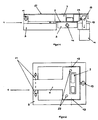
- Fig. 1 schematically shows a side view of a device 1 according to the invention in a sectional view.
- the device 1 has a first contact section 3 in the form of an AS plate, which is vertically oscillating or rotatable in a carrier device 5, designed here as a stable, circumferential carrier frame.
- the second contact section 7 serves to cover and clamp an external functional device 9, here in the form of a blood-carrying disposable cassette.
- the pressing device 11 can be designed to press the door as a second contact section 7 via a locking device 13, here a bolt, against the AS plate as the first contact section 3.
- the first contact portion 3 is by means of an axle or shaft 14 at two storage points 15 on its narrow side (its upper and lower side in Fig. 2 ) stored in the carrier device 5.
- the joint 17 and the locking device 13 of the second contact portion 7 are each mounted centrally on the support means 5 and connect the second contact portion 7 with the support means fifth
- the locking device 13 has an integrated sensor as a detection device 23.
- the sensor can detect, for example, whether the door is closed as a second contact section 7.
- the door cover 27 may have transparent areas.
- the Fig. 2 shows a front view of the device according to the invention the Fig. 1 without door cover 27.
- the door has connecting elements 29 for supplying the disposable cassette with pressure.
- the Fig. 3 shows the device of the invention the Fig. 1 without the door and without the door cover 27.
- a mat as a sealing device 21 below the Disposable cassette on the AS-plate (the latter is in Fig. 3 not to be seen, as obscured by the disposable cassette and the mat).
- Fig. 3 For example, openings 19 for receiving fasteners such as locating pins (not shown) are shown. Such Positioning mandrels may be suitable for fixing the external functional device to the first contact section according to the hole-slot principle.
- the present invention is not limited to the embodiment described above, this is for illustrative purposes only.
Landscapes
- Health & Medical Sciences (AREA)
- Heart & Thoracic Surgery (AREA)
- Vascular Medicine (AREA)
- Life Sciences & Earth Sciences (AREA)
- General Health & Medical Sciences (AREA)
- Anesthesiology (AREA)
- Biomedical Technology (AREA)
- Hematology (AREA)
- Veterinary Medicine (AREA)
- Animal Behavior & Ethology (AREA)
- Engineering & Computer Science (AREA)
- Public Health (AREA)
- Cardiology (AREA)
- Emergency Medicine (AREA)
- Urology & Nephrology (AREA)
- External Artificial Organs (AREA)
- Infusion, Injection, And Reservoir Apparatuses (AREA)
Description
- Die vorliegende Erfindung betrifft eine Vorrichtung zum Verbinden wenigstens einer externen Funktionseinrichtung mit einer Anordnung gemäß dem Oberbegriff des Anspruchs 1. Sie betrifft ferner ein Verfahren zum Verbinden wenigstens einer externen Funktionseinrichtung mit einer Anordnung unter Verwenden der erfindungsgemäßen Vorrichtung gemäß dem Oberbegriff des Anspruchs 13, und eine Anordnung gemäß dem Anspruch 14, die eine erfindungsgemäße Vorrichtung aufweist.
- Bei technischen Anordnungen, wie beispielsweise Behandlungsmaschinen der Medizintechnik, labortechnischen Anordnungen oder auch Anordnungen zur Nahrungsmittelherstellung, ist oftmals eine funktionelle Ankopplung externer Funktionseinrichtungen an die Anordnung vorgesehen. Ein Beispiel einer solchen externen Funktionseinrichtung ist eine Disposable-Kassette, wie sie in der
DE 10 2007 042 964 beschrieben ist. - Eine funktionelle Ankopplung derartiger externer Funktionseinrichtungen setzt üblicherweise deren korrekte Positionierung und/oder Fixierung auf bzw. an der Anordnung voraus, damit anordnungsseitige Sensoren und Aktoren mit der externen Funktionseinrichtung fehlerfrei zusammenwirken können.
- Aufgabe der vorliegenden Erfindung ist es, eine weitere Vorrichtung zum Verbinden wenigstens einer externen Funktionseinrichtung mit einer Anordnung bereitzustellen. Ferner soll ein Verfahren zum Verbinden wenigstens einer externen Funktionseinrichtung sowie eine Anordnung, welche eine derartige Vorrichtung aufweist, angegeben werden.
- Die erfindungsgemäße Aufgabe wird durch eine Vorrichtung mit den Merkmalen des Anspruchs 1 gelöst.
- Die erfindungsgemäße Vorrichtung dient zum Verbinden oder zur Verbindung, insbesondere zum Ankoppeln, wenigstens einer externen Funktionseinrichtung mit einer Anordnung und weist dazu wenigstens eine Aufnahmeeinrichtung mit wenigstens einem ersten Kontaktabschnitt und wenigstens einem zweiten Kontaktabschnitt auf, zwischen welchen die externe Funktionseinrichtung aufgenommen werden kann. Dabei ist wenigstens der erste Kontaktabschnitt und/oder der zweite Kontaktabschnitt bewegbar angeordnet, vorzugsweise gelagert. Unter "bewegbar" ist vorzugsweise eine selbstnachführende Bewegbarkeit oder Beweglichkeit des bewegbaren Kontaktabschnitts zu verstehen.
- Im Sinne der vorliegenden Erfindung kann vom Begriff "bewegbar" jedoch eine Beweglichkeit, wie beispielsweise das bloße Schwenken um eine Aufhängung an einem Scharnier, wie beispielsweise das bekannte Schwenken einer Tür, ausgeschlossen sein. Diese Bedeutung kann von der vorliegenden Erfindung im Zusammenhang mit dem Begriff "bewegbar" alternativ jedoch explizit umfasst sein.
- Der erste und/oder der zweite Kontaktabschnitt können derart vorgesehen sein, dass sie pendelbar angeordnet, vorzugsweise gelagert, sind, also zumindest beim Vorgang des Verbindens in wenigstens einer Richtung pendeln können.
- Eine "externe Funktionseinrichtung", wie sie hierin verwendet wird, kann ein Wärmetauscher, eine Messeinrichtung, eine multifunktionale Disposable-Kassette oder dergleichen sein.
- Eine erfindungsgemäß in Betracht gezogene externe Funktionseinrichtung kann zum Leiten medizinischer Fluide, wie Blut, Substituatflüssigkeit oder dergleichen geeignet sein. Eine derartige externe Funktionseinrichtung kann beispielsweise eine blutführende Kassette sein. Sie kann Teile eines extrakorporalen Blutkreislaufs enthalten. Insbesondere kann sie als eine Disposable-Kassette ausgestaltet sein, wie sie in der
DE 10 2007 042 964 beschrieben ist. Deren gesamte diesbezügliche Offenbarung wird durch Bezugnahme Teil der vorliegenden Unterlagen. Dabei gilt im Zusammenhang mit der vorliegenden Offenbarung, dass die Ausdrücke "kann aufweisen", "kann sein" und dergleichen synonym zu den hier und auch an anderer Stelle ebenfalls verwendeten Ausdrücken "weist bevorzugt auf", "ist bevorzugt" und dergleichen zu verstehen sind. - Die externe Funktionseinrichtung kann vorzugsweise Energie, Messwerte und/oder mechanische Bewegungen und Kräfte auf die Anordnung übertragen oder von dieser empfangen sowie in Fluidverbindung mit der Anordnung stehen. Sie kann von der Anordnung alternativ jedoch auch nur gehalten werden und mit dieser nicht in Wechselwirkung und/oder Signalkommunikation und/oder Fluidverbindung stehen.
- Die aufzunehmende oder zu verbindende externe Funktionseinrichtung kann an wenigstens einer Oberfläche eine Abdeckung aufweisen. Eine solche Abdeckung kann eine Folie sein. Die Folie kann zum Aufnehmen von Sensoren und/oder Aktoren und/oder Leitungen und/oder Teilen derselben vorgesehen sein. Die Folie kann Öffnungen zum Aufnehmen derartiger Komponenten aufweisen und/oder derartige Komponenten können in die Folie und/oder einen Folienverbund integriert sein.
- Eine "Anordnung" im Sinne der vorliegenden Erfindung ist eine medizintechnische Anordnung, wie eine Blutbehandlungsvorrichtung, zum Beispiel eine Dialysevorrichtung, eine Hämodialysevorrichtung, eine Hämodiafiltrationsvorrichtung oder dergleichen.
- Der Begriff "Verbinden", wie er hierin verwendet wird, kann ein funktionelles und/oder mechanisches Verbinden der externen Funktionseinrichtung mit der Anordnung bezeichnen oder umfassen.
- Der Begriff "Ankoppeln", wie er hierin verwendet wird, kann ein funktionelles und/oder mechanisches Verbinden der externen Funktionseinrichtung mit einem Koppelpartner auf der Seite der Anordnung mit einer Wechselwirkung oder Signalkommunikation oder Fluidverbindung zwischen externer Funktionseinrichtung und Anordnung im angekoppelten Zustand der externen Funktionseinrichtung bezeichnen oder umfassen. Ein "Koppelpartner der Anordnung" kann zum Beispiel eine Messeinrichtung, wie beispielsweise ein Sensor, sein. Er kann als eine Fluidleitung und dergleichen ausgestaltet sein.
- Eine "Aufnahmeeinrichtung" im Sinne der vorliegenden Erfindung ist eine Einrichtung, die zum Aufnehmen wenigstens einer externen Funktionseinrichtung geeignet ist. Dabei kann Aufnehmen ein Halten, ein Umfassen, ein Umgreifen, ein Bedecken der externen Funktionseinrichtung und dergleichen sowie Kombinationen hieraus bedeuten.
- Der "erste Kontaktabschnitt" der Aufnahmeeinrichtung ist bevorzugt an der erfindungsgemäßen Vorrichtung selbst oder an einer Anordnung vorgesehen. Er kann beweglich, z.B. in vertikaler und/oder horizontaler oder anderer Richtung - jeweils bezogen auf den Erdmittelpunkt - pendelnd, innerhalb der Vorrichtung oder der Anordnung angeordnet sein.
- Der erste Kontaktabschnitt kann verschiedene Funktionen übernehmen. So kann er beispielsweise zum Ausrichten der externen Funktionseinrichtung, zu ihrer Verrastung und/oder zur Übertragung einer Verpresskraft auf die externe Funktionseinrichtung sowie Kombinationen der vorgenannten Funktionen dienen.
- Der erste Kontaktabschnitt kann weitere Einrichtungen zum Unterstützen eines Verpressens der externen Funktionseinrichtung und/oder Halten derselben, wie beispielsweise eine Verpresseinrichtung und/oder eine Verriegelungseinrichtung, aufweisen oder mit solchen Einrichtungen verbunden sein.
- Der erste Kontaktabschnitt kann eine "Ankoppelfläche", eine "Aktivator-/Sensor-Platte" (kurz "AS-Platte") oder ein Maschineninterface sein.
- Der Begriff "Ankoppelfläche" kann beispielsweise wenigstens einen Abschnitt einer Oberseite eines Trägerelements und/oder eines Auflage- oder Stützelements und/oder einer Messeinrichtung oder dergleichen der Anordnung und/oder der Vorrichtung bezeichnen.
- Eine "AS-Platte" kann Aktoren und/oder Sensoren und/oder Leitungen zum Ankoppeln an die externe Funktionseinrichtung oder Teile derselben aufweisen.
- Mittels der Ankoppelfläche, welche flach bzw. eben sein kann, aber nicht sein muss, kann eine Wechselwirkung oder Signalkommunikation zwischen der externen Funktionseinrichtung und einem Abschnitt der Vorrichtung oder der Anordnung hergestellt werden.
- "Aktoren" im hier gebrauchten Sinn schließen, ohne darauf beschränkt zu sein, mechanische und/oder pneumatische und/oder elektrische Komponenten, wie beispielsweise Ventile, Stell- und/oder Regelglieder, Stellmotoren, Druckkolben, und dergleichen ein.
- "Sensoren", wie sie hier bezeichnet sind, schließen, wiederum ohne darauf beschränkt zu sein, elektrische, optische, akustische, virtuelle und/oder digitale Sensoren, Messwertaufnehmer und/oder Messwertfühler und dergleichen ein.
- Ein Sensor kann bestimmte physikalische und/oder chemische Eigenschaften und/oder eine Änderung derselben, wie eine Zunahme oder eine Abnahme eines Effektes, einer Ausprägung, einer Beschaffenheit und dergleichen, wie beispielsweise Temperatur, Druck, Feuchtigkeit, optische Signale, wie beispielsweise Helligkeit und/oder eine optische Änderung einer Zusammensetzung, Wärmestrahlung, Schall, Durchflussmengen, und/oder die stoffliche Beschaffenheit seiner Umgebung qualitativ oder quantitativ erfassen.
- Derartige Sensoren können als passive Sensoren oder aktive Sensoren ausgelegt sein.
- Leitungen, wie sie erfindungsgemäß eingesetzt werden können, können, ohne darauf beschränkt zu sein, Fluidleitungen, wie beispielsweise blutführende Kanäle, Substituatleitungen, elektrische Leitungen, Leitungen zur Signalkommunikation, wie beispielsweise Glasfaserkabel, und dergleichen umfassen.
- Der "zweite Kontaktabschnitt" der Aufnahmeeinrichtung kann wie der erste Kontaktabschnitt ausgestaltet sein und vorzugsweise dieselben Funktionen übernehmen.
- Der "zweite Kontaktabschnitt" kann eine Andruckplatte sein. Er kann flach, stufig, wellig oder auf andere Weise ausgestaltet sein. Er kann punktförmig oder flächig mit der externen Funktionseinrichtung in Kontakt treten. Er kann einen Abschnitt aufweisen, welcher in seiner Geometrie einer Erstreckung der anzukoppelnden externen Funktionseinrichtung - im angekoppelten oder im nicht angekoppelten Zustand - entspricht. Dies kann deren Aufnahme und/oder Ausrichtung erleichtern oder begünstigen.
- Der zweite Kontaktabschnitt kann beweglich oder starr ausgestaltet sein.
- Der zweite Kontaktabschnitt kann vorgesehen sein, um mittelbar oder unmittelbar mit der externen Funktionseinrichtung in Kontakt zu treten.
- Der zweite Kontaktabschnitt kann eine Tür oder ein Deckel zum Verschließen eines Inneren der erfindungsgemäßen Vorrichtung oder der Anordnung oder ein Abschnitt jeweils hiervon sein.
- Vorteilhafte Weiterentwicklungen der vorliegenden Erfindung sind jeweils Gegenstand der Unteransprüche.
- In einer bevorzugten erfindungsgemäßen Ausführungsform weist die Vorrichtung wenigstens eine umlaufend ausgestaltete Trägereinrichtung auf. Der erste Kontaktabschnitt kann in einem Inneren der Trägereinrichtung gelagert sein.
- Eine solche "Trägereinrichtung" kann eine stabile Trägereinrichtung, wie beispielsweise ein Trägerrahmen, sein. Er kann Teil der Aufnahmeeinrichtung zum Aufnehmen der wenigstens einen externen Funktionseinrichtung sein.
- Die Trägereinrichtung kann kraft- und/oder form- und/oder stoffschlüssig mit der Anordnung verbunden sein.
- Die Trägereinrichtung kann mit dem ersten und/oder dem zweiten Kontaktabschnitt verbunden sein.
- Insbesondere kann der erste Kontaktabschnitt im Fall seiner Ausgestaltung als AS-Platte in Richtung zum zweiten Kontaktabschnitt und/oder der externen Funktionseinrichtung hin an einer Oberfläche eines von der Trägereinrichtung umschlossenen Abschnitts bzw. eines Inneren angeordnet sein.
- Der erste Kontaktabschnitt kann derart im Inneren der Trägereinrichtung angeordnet sein, dass eine Oberfläche des ersten Kontaktabschnitts und eine Oberfläche der Trägereinrichtung in einer Ebene liegen. Insbesondere können die in Richtung des zweiten Kontaktabschnitts und/oder der externen Funktionseinrichtung gerichtete Oberfläche des ersten Kontaktabschnitts und die in Richtung des zweiten Kontaktabschnitts und/oder der externen Funktionseinrichtung gerichtete Oberfläche der Trägereinrichtung in einer Ebene liegen.
- Zwischen dem im Inneren der Trägereinrichtung angeordneten ersten Kontaktabschnitt und der Trägereinrichtung kann eine Öffnung bzw. ein freier Raum vorhanden sein. Eine solche Öffnung kann einen - insbesondere umlaufenden - Spalt bilden.
- Der erste Kontaktabschnitt kann im Inneren der Trägereinrichtung beweglich gelagert sein. Der erste Kontaktabschnitt kann pendelnd, im Besonderen entlang einer auf seiner Oberfläche senkrecht stehenden Achse, pendelnd angeordnet sein.
- In einer weiter bevorzugten Ausführungsform ist wenigstens einer der beiden Kontaktabschnitte um wenigstens eine Drehachse drehbar gelagert. Die dabei erzielbare Drehbarkeit oder die Pendelmöglichkeit sind als Formen einer Bewegbarkeit im Sinne der vorliegenden Erfindung zu verstehen.
- Wenn im Folgenden von einer Drehachse oder Achse die Rede ist, kann hierunter erfindungsgemäß auch eine Mehrzahl von Achsen zu verstehen sein, wann immer der Fachmann dies als technisch möglich erkennt. Auch Dreh- oder Pendelbewegungen, welche zugleich in mehr als einer Achsenrichtung möglich sind, werden im Folgenden der besseren Lesbarkeit wegen als solche in einer Achsenrichtung subsumiert. Dies soll die vorliegende Erfindung jedoch nicht einschränken.
- Dabei kann die Drehachse eine "körperliche" Drehachse sein. Eine körperliche Drehachse im Sinne der vorliegenden Erfindung kann eine gegenständliche Achse sein. Sie kann eine durch Verbinden wenigstens eines Kontaktabschnittes mit der Trägereinrichtung gebildete, räumlich starre Achse sein. Sie kann horizontal oder vertikal, bezogen auf eine während der Verwendung der Anordnung übliche Ausrichtung der Anordnung oder bezogen auf den Erdmittelpunkt, ausgerichtet sein.
- Eine körperliche Achse kann als eine feststehende Achse, oder als eine sich drehende Welle ausgestaltet sein. Vorzugsweise weist sie wenigstens ein geeignetes Lager auf. Sie kann jeweils durch eine Lagerverbindung des ersten Kontaktabschnitts und/oder des zweiten Kontaktabschnitts mit der Trägereinrichtung und/oder einem anderen Bauteil der Anordnung ausgestaltet sein.
- Beispiele für derartige Lagerverbindungen schließen, ohne darauf beschränkt zu sein, Lagerungsstifte, die in geeignete Lagerungsaufnahmeeinrichtungen eingebracht und/oder eingelegt werden, Kugellager, Rollenlager, Wälzlager, Gleitlager und dergleichen ein.
- Unter "Achse" kann erfindungsgemäß alternativ auch eine Raumachse oder eine Achse in einer Raumrichtung verstanden werden. Sie ist in diesem Fall somit virtuell und im Gegensatz zur zuvor erläuterten gegenständlichen Achse nicht greifbar.
- Die Achse im Sinne der vorliegenden Erfindung kann als ein Drehzentrum oder ein Drehmittelpunkt zu verstehen sein, um welche der Kontaktabschnitt gedreht, also bewegt werden kann. Die Bewegbarkeit des Kontaktabschnitts um die Achse kann eine Pendelbewegung der externen Funktionseinrichtung bei ihrem Verbinden mit der Anordnung oder der Vorrichtung ermöglichen.
- Die Achse kann in jeder Ausführungsform durch den Kontaktabschnitt verlaufen. Sie kann jedoch auch außerhalb verlaufen.
- Die Achse kann in einem Verbindungszustand der externen Funktionseinrichtung durch das Innere der Vorrichtung und/oder durch das Innere der Anordnung verlaufen.
- Die Achse kann vorzugsweise derart verlaufen, dass sie eine Dreh- oder Pendelbewegung um sie herum allein durch ein Drehen oder Pendeln des betreffenden Kontaktabschnitts, nicht aber weiterer Bauelemente der Vorrichtung oder Anordnung, ermöglicht. Dies ist insbesondere dann vorzugsweise möglich, wenn der drehbare Kontaktabschnitt die Ankoppelfläche für die externe Funktionseinrichtung bzw. das sogenannte Maschineninterface ist.
- Die Achse kann derart angeordnet sein, dass sie Ausgleichbewegungen wenigstens eines Kontaktabschnitts zum Ausgleichen von Toleranzen, Passungenauigkeiten, Verschleißerscheinungen usw. ermöglicht, darüber hinaus aber keine Drehbewegung eines Bauteils ermöglicht.
- In einer bevorzugten Ausführungsform ist wenigstens einer der beiden Kontaktabschnitte mittels wenigstens eines Kugelgelenks gelagert.
- Ein mittels Kugelgelenk gelagerter Kontaktabschnitt kann in alle Raumrichtungen beweglich sein. Beispielsweise kann der erste Kontaktabschnitt auf diese Weise in allen Raumrichtungen drehbar gelagert sein.
- In einer weiter bevorzugten Ausführungsform weisen sowohl wenigstens der erste als auch der zweite Kontaktabschnitt Drehachsen auf. Vorzugsweise sind ihre Drehachsen (alle oder nur einige davon) parallel zueinander angeordnet. Die beiden Drehachsen können unabhängig voneinander als gegenständliche, körperliche, feste oder virtuelle Drehachse ausgebildet sein. Sie können gleich oder voneinander verschieden ausgestaltet sein.
- In einer weiter bevorzugten Ausführungsform ist vorgesehen, dass wenigstens eine Kontaktfläche des ersten und/oder des zweiten Kontaktabschnitts und wenigstens eine Kontaktfläche der externen Funktionseinrichtung so angeordnet werden, dass sie in einem angekoppelten Zustand der externen Funktionseinrichtung plan oder im Wesentlichen plan aufeinander zum Liegen kommen.
- Eine "Kontaktfläche" des ersten und/oder des zweiten Kontaktabschnitts und eine Kontaktfläche der externen Funktionseinrichtung bezeichnen erfindungsgemäß diejenigen Oberflächen des jeweiligen Kontaktabschnitts und der externen Funktionseinrichtung, die einander im angekoppelten Zustand der externen Funktionseinrichtung an der Anordnung jeweils gegenüberliegen.
- Der Begriff "plan", wie er erfindungsgemäß zu verstehen ist, soll das ebene oder im Wesentlichen ebene Aneinanderliegen der Kontaktabschnitte mit der externen Funktionseinrichtung bezeichnen. Dabei können der erste und der zweite Kontaktabschnitt, im Verbindungszustand derart zueinander ausgerichtet sein können, dass ihre jeweils einander gegenüber liegenden Flächen zueinander parallel oder im Wesentlichen parallel sind.
- Auf diese Weise kann es vorteilhaft möglich sein, ein mögliches Verkanten der Kontaktabschnitte und der externen Funktionseinrichtung während des Vorgangs des Ankoppelns zu vermeiden. Eine optimale funktionelle Ankopplung der Komponenten der externen Funktionseinrichtung kann somit vorteilhaft sichergestellt werden. Übermäßige Materialbeanspruchung kann vorteilhaft vermieden werden.
- Ein "angekoppelter Zustand" der externen Funktionseinrichtung bezeichnet ebenso wie ein "Verbindungszustand" erfindungsgemäß einen Zustand, in dem die externe Funktionseinrichtung in ihrem Gebrauchszustand funktionell mit der Anordnung verbunden ist. Ein solcher Zustand kann zum Ausführen einer Funktion, wie beispielsweise einer Behandlung medizinischer Fluide, wie einer Blutbehandlung, vorgesehen sein.
- In einer weiteren bevorzugten Ausführungsform weist die erfindungsgemäße Vorrichtung wenigstens eine Verpresseinrichtung zum Verpressen der externen Funktionseinrichtung zwischen dem ersten Kontaktabschnitt und dem zweiten Kontaktabschnitt auf.
- Eine "Verpresseinrichtung" zur Verwendung in der vorliegenden Erfindung kann ein Verpressaktor, eine elektrische Verpresseinrichtung, ein Stellmotor, eine pneumatische Verpresseinrichtung, ein Ventil, ein Kolben und dergleichen sein oder aufweisen sowie Kombinationen hiervon.
- Die Verpresseinrichtung kann mit der Trägereinrichtung und/oder dem ersten Kontaktabschnitt und/oder dem zweiten Kontaktabschnitt und/oder einem anderen Bauteil der Vorrichtung und/oder der Anordnung verbunden sein. Sie kann kraft- und/oder formschlüssig mit wenigstens einer der vorstehend genannten Komponenten verbunden sein.
- Die Verpresseinrichtung kann eine Verpresskraft zum Verpressen der externen Funktionseinrichtung zwischen den Kontaktabschnitten aufbringen und/oder übertragen. Eine derartige "Verpresskraft kann eine pneumatische Kraft, eine elektromotorische Kraft, magnetische Kraft, induktive Kraft und dergleichen sein.
- Die Verpresseinrichtung kann zum Aufrechterhalten des verpressten Zustands der externen Funktionseinrichtung zwischen den beiden Kontaktabschnitten über eine Zeitdauer hinweg ausgelegt sein. Sie kann entsprechende Einrichtungen zum Aufrechterhalten, Steuern oder Regeln der Verpresskraft aufweisen.
- Die Verpresseinrichtung kann ausgestaltet sein, um die Dichtigkeit der externen Funktionseinrichtung durch korrekten Sitz derselben auf einem der Kontaktabschnitte - beispielsweise in Gestalt einer Ankoppelebene oder eines Maschineninterface - sicherzustellen.
- In einer weiteren bevorzugten Ausführungsform kann die Vorrichtung ferner wenigstens eine Verriegelungseinrichtung zum Fixieren des verpressten Zustands der externen Funktionseinrichtung zwischen dem ersten Kontaktabschnitt und dem zweiten Kontaktabschnitt aufweisen.
- Eine "Verriegelungseinrichtung" im Sinne der vorliegenden Erfindung, kann ein Riegel, ein Schloss, eine Sperre, eine Lasche, eine Steckverbindung, eine Verrasteinrichtung und dergleichen sein.
- Die Verriegelungseinrichtung kann eine weitere zum Verpressen erforderliche Kraft aufbringen und eine Gesamtverpresskraft erhöhen. Hierzu kann sie eine entsprechende Einrichtung aufweisen. Auf diese Weise kann die funktionelle Ankopplung der externen Funktionseinrichtung zwischen dem ersten Kontaktabschnitt und dem zweiten Kontaktabschnitt in vorteilhafter Weise weiter sichergestellt werden.
- Die Verriegelungseinrichtung kann mit der Trägereinrichtung verbunden sein. Die Verpresseinrichtung kann den zweiten Kontaktabschnitt über die Verriegelungseinrichtung gegen den ersten Kontaktabschnitt verpressen.
- In einer weiter bevorzugten Ausführungsform weist die Verriegelungseinrichtung wenigstens eine erste Erfassungseinrichtung zum Erfassen einer Position und/oder eines Zustands des ersten Kontaktabschnitts und/oder des zweiten Kontaktabschnitts auf.
- Eine "Erfassungseinrichtung", wie sie hierin eingesetzt werden kann, kann beispielsweise ein Sensor und/oder Detektor sein, der eine Position und/oder einen Zustand des ersten Kontaktabschnitts und/oder des zweiten Kontaktabschnitts erkennt und gegebenenfalls auswertet.
- Eine "Position und/oder ein Zustand" des ersten Kontaktabschnitts und/oder des zweiten Kontaktabschnitts kann eine räumliche Anordnung und/oder Ausrichtung des ersten Kontaktabschnitts und/oder des zweiten Kontaktabschnitts bezeichnen. Sie kann eine Anordnung des ersten Kontaktabschnitts und des zweiten Kontaktabschnitts relativ zueinander bezeichnen.
- Die Erfassungseinrichtung und/oder die Vorrichtung und/oder die Anordnung kann Einrichtungen zum Auswerten und/oder Steuern und/oder Regeln, insbesondere zum Korrigieren, der Position und/oder des Zustands des ersten Kontaktabschnitts und/oder des zweiten Kontaktabschnitts aufweisen. Derartige Einrichtungen können untereinander in Signalkommunikation stehen.
- Die Verriegelungseinrichtung kann eine geeignete Sensoranordnung zum Erkennen der Zustände des zweiten Kontaktabschnitts, wie beispielsweise eines Zustands "Tür geschlossen" und/oder "Tür verriegelt", aufweisen. Erfindungsgemäß können eine Anzeige- und/oder eine Alarmeinrichtung zum Kommunizieren des erkannten Zustands vorgesehen sein.
- In einer weiteren bevorzugten Ausführungsform sind der erste Kontaktabschnitt und/oder der zweite Kontaktabschnitt über ein Gelenk mit der Trägereinrichtung, der Vorrichtung oder der Anordnung verbunden.
- Ein "Gelenk", wie es erfindungsgemäß verwendet kann, kann ein stabiles Gelenk, wie beispielsweise ein Scharnier, ein Türgelenk, einen Hebel und dergleichen bezeichnen.
- Ein Türgelenk ist vorzugsweise einachsig ausgeführt.
- Der über ein derartiges Gelenk mit der Trägereinrichtung verbundene Kontaktabschnitt kann vorzugsweise um eine sich beispielsweise in vertikaler Richtung erstreckenden Achse drehbar sein. Er kann insbesondere in Form einer Tür und/oder Abdeckung auf- und zuklappbar sein.
- In einer wiederum weiter bevorzugten Ausführungsform ist wenigstens einer der Kontaktabschnitte oder eine Kontaktfläche oder eine Anpressfläche hiervon drehbar oder schwenkbar mit der Vorrichtung oder der Anordnung verbunden - beispielsweise mittels einer Tür oder als Teil einer Tür. Dabei liegt die Drehachse - beispielsweise als Drehachse eines Türgelenks der Tür - in einer Ebene mit - und vorzugsweise zudem parallel zu - einer Drehachse eines in dieser Ausführungsform drehbar gelagerten anderen Kontaktabschnitts.
- In einer weiter bevorzugten Ausführungsform weisen der erste Kontaktabschnitt und/oder der zweite Kontaktabschnitt und/oder das Gelenk wenigstens eine Einrichtung zum Aufnehmen von Anbindungselementen zum funktionellen Anbinden der externen Funktionseinrichtung an die Anordnung auf.
- Eine solche "Einrichtung zum Aufnehmen von Anbindungselementen" kann eine Öffnung, insbesondere eine sich durch die Komponente erstreckende Öffnung, wie beispielsweise eine Durchführung sein. Sie kann in ihrem Inneren zum Aufnehmen von Leitungen, Führungen, Zügen oder dergleichen ausgestaltet sein.
- "Anbindungselemente", wie sie im Rahmen der vorliegenden Erfindung in Betracht gezogen werden, können Leitungen, wie elektrische und/oder pneumatische Leitungen, Kabel, wie Glasfaserkabel, Fluidleitungen und dergleichen, umfassen.
- Derartige Anbindungselemente können die externe Funktionseinrichtung beispielsweise mit Druck versorgen. Ferner können über sie auch Sensoren und/oder an die externe Funktionseinrichtung angekoppelt werden.
- In einer weiter bevorzugten Ausführungsform weisen der erste Kontaktabschnitt und/oder der zweite Kontaktabschnitt wenigstens einen transparenten Abschnitt auf.
- Der Begriff "transparent", wie er in der vorliegenden Erfindung verwendet wird, bezeichnet eine - insbesondere für das menschliche Auge - durchsichtig ausgelegte Komponente.
- Ein "transparenter Abschnitt" kann, ohne darauf beschränkt zu sein, aus Glas, durchsichtigem Kunststoff, durchsichtiger Folie oder dergleichen ausgebildet sein oder dergleichen umfassen.
- Ein transparenter Abschnitt kann in vorteilhafter weise ein Betrachten und/oder optisches Überwachen eines Inneren der Anordnung zulassen. Er kann opak sein.
- Ein Kontaktabschnitt, zum Beispiel der zweite Kontaktabschnitt, insbesondere wenn in Form einer Tür ausgestaltet, kann eine stabile Trägerstruktur mit einer in Teilbereichen vorgesehenen transparenten Abdeckung aufweisen. Eine derartige Ausführung kann einem Anwender der Anordnung in vorteilhafter weise erlauben, interessierende Bereiche der externen Funktionseinrichtung optisch von außen zu überwachen.
- In einer weiter bevorzugten Ausführungsform können der erste Kontaktabschnitt und/oder der zweite Kontaktabschnitt wenigstens eine Positionierungseinrichtung zum Positionieren der externen Funktionseinrichtung innerhalb der Vorrichtung aufweisen.
- Eine "Positionierungseinrichtung" im Sinne der vorliegenden Erfindung kann als eine zum definierten Aufnehmen und/oder räumlichen Positionieren und/oder kraft- und/oder formschlüssigen Befestigen der externen Funktionseinrichtung am Kontaktabschnitt ausgestaltet sein. Sie kann beispielsweise als Positionierstift, Positionierdorn und dergleichen ausgestaltet sein.
- Die externe Funktionseinrichtung kann wenigstens eine Einrichtung zum Aufnehmen der Positioniereinrichtung, wie beispielsweise eine Öffnung, insbesondere eine Durchgangsöffnung, aufweisen.
- Das Positionieren der externen Funktionseinrichtung innerhalb der Vorrichtung kann beispielsweise nach dem so genannten Loch-Langloch-Prinzip mittels geeigneter Einrichtungen erfolgen.
- In einer weiter bevorzugten Ausführungsform weist die Vorrichtung wenigstens eine Abdichtungseinrichtung auf.
- Eine solche "Abdichtungseinrichtung" kann zum Abdichten eines ersten Volumens der Vorrichtung gegen ein zweites Volumen der Vorrichtung geeignet sein.
- Eine solche Abdichtungseinrichtung kann eine Matte sein. Sie kann eine Gummimatte sein. Sie kann als Mehrkomponenten-Abdichtungseinrichtung ausgelegt sein. Sie kann wenigstens ein elastomeres Material aufweisen. Sie kann zwischen dem ersten Kontaktabschnitt und dem zweiten Kontaktabschnitt angeordnet sein. Sie kann für den Gebrauchszustand der externen Funktionseinrichtung bzw. für den Verbindungszustand zwischen einem bewegbaren Kontaktabschnitt und der externen Funktionseinrichtung vorgesehen sein.
- Die Abdichtungseinrichtung kann Sensoren und/oder Aktoren und/oder Leitungen und/oder Teile derselben aufweisen und/oder zum Aufnehmen derselben ausgelegt sein. Die Abdichtungseinrichtung kann mit derartigen Komponenten integriert ausgebildet sein. Die Komponenten können form- und/oder kraft- und/oder stoffschlüssig mit der Abdichtungseinrichtung verbunden sein.
- Zu den geeigneten Abdichtungseinrichtungen zählen solche, wie sie in einer der Druckschriften
DE 10 2007 042 964 ,DE 10 2008 062 037 oder der am selben Anmeldetag wie die vorliegende Anmeldung von der vorliegenden Anmelderin beim Deutschen Patent- und Markenamt angemeldeten PatentanmeldungDE 10 2009 012 632.5 mit dem Titel "Abdichtungseinrichtung zum Abdichten eines Volumens einer medizinischen Behandlungsanordnung gegen ein weiteres Volumen sowie Anordnung und Verfahren" offenbart sind. Auf die diesbezügliche Offenbarung der genannten Patentanmeldungen wird hierin vollinhaltlich Bezug genommen. - Die erfindungsgemäße Aufgabe wird ferner durch ein Verfahren gemäß dem Anspruch 13 gelöst.
- Ein solches Verfahren umfasst das Verbinden wenigstens einer externen Funktionseinrichtung mit der Anordnung unter Verwenden der erfindungsgemäßen Vorrichtung.
- Die erfindungsgemäße Aufgabe wird ebenso durch eine Anordnung gemäß dem Anspruch 14 gelöst. Eine solche erfindungsgemäße Anordnung weist wenigstens eine erfindungsgemäße Vorrichtung auf. In einer bevorzugten Ausführungsform ist die erfindungsgemäße Anordnung eine Blutbehandlungsvorrichtung, insbesondere eine Dialysevorrichtung, eine Hämodialysevorrichtung, eine Hämodiafiltrationsvorrichtung oder dergleichen.
- Zur Vermeidung von Wiederholungen wird an dieser Stelle auf die vorstehend beschriebenen Ausführungen verwiesen, die ungeschmälert auf jegliche Ausführungsformen des erfindungsgemäßen Verfahrens und der erfindungsgemäßen Anordnung zutreffen. Zudem sind die genannten Vorteile ungeschmälert erzielbar.
- Die erfindungsgemäße Vorrichtung ist vorteilhaft zum präzisen Ankoppeln einer externen Funktionseinrichtung an eine Anordnung geeignet. Durch den wenigstens einen, beispielsweise in einer Rotationsrichtung, beweglich ausgestalteten Kontaktabschnitt kann das Ausgleichen auftretender Toleranzen zwischen den einzelnen Bauteilen möglich sein und eine optimale mechanische und/oder funktionelle Ankopplung sichergestellt werden. Aufwändige Ankoppelvorgänge, wie sie beispielsweise in der Patentanmeldung mit der Veröffentlichungsnummer
DE 10 2007 04 29 64 beschrieben sind, deren diesbezügliche Offenbarung durch Verweis hierin wiederum aufgenommen ist, ist mittels der erfindungsgemäßen Vorrichtung vorteilhaft auf einfache, schnelle und fehlerfreie Weise möglich. - Die durch Fertigungstoleranzen, elastisches Werkstoffverhalten sowie Verschleiß der einzelnen Komponenten im Laufe ihrer Lebensdauer allgemein erschwerte, sichere und dichte Ankopplung - beispielsweise unter der Forderung gleichmäßig über die Kontaktflächen verteilten hohen Drucks - kann durch die Beweglichkeit und Nachgiebigkeit bzw. Selbstnachführung eines Kontaktabschnitts in wenigstens einer Raumrichtung in vorteilhafter Weise sichergestellt werden.
- Auf Grund der Möglichkeit der selbsttätigen Anpassung eines Kontaktabschnitts kann es in vorteilhafter Weise möglich sein, eine geeignete, sichere und fehlerfreie sowie verschleißarme Ankopplung der Sensoren und Aktoren der Ankoppelfläche - auch als Maschineninterface bezeichnet - und damit die angestrebte Funktion derselben mit Bezug auf ihre Koppelpartner der externen Funktionseinrichtung - und umgekehrt - sicherzustellen.
- Da alle wesentlichen Komponenten auf einer einzigen, stabilen Trägereinrichtung montiert und positioniert sein können, kann in vorteilhafter Weise eine präzise Verpressung der Bauteile mit relativ hohen Kräften erreicht werden.
- Aufgrund der Beweglichkeit oder Drehbarkeit des Kontaktabschnitts um eine Achse kann eine Verpresskraft auf vorteilhafte Weise gleichmäßig, auf eine Fläche oder auf mehrere Punkte verteilt werden. Daher können bei Bedarf vorteilhaft auch vergleichsweise hohe Kräfte aufgebracht werden. Die Beweglichkeit oder Drehbarkeit um eine Achse kann sicherstellen, dass es zu keinen unzulässigen Spitzenbelastungen durch Druckaufbringung kommt.
- Dies gilt insbesondere, wenn mittels der erfindungsgemäß vorgesehenen drehbaren Anordnung wenigstens eines Kontaktabschnitts, vorzugsweise zwei Kontaktabschnitten, um jeweils eine Achse in vorteilhafter Weise die Kontaktflächen stets zueinander parallel ausgerichtet sein können. Dies erlaubt wiederum eine optimale Ankopplung der wenigstens einen externen Funktionseinrichtung bei Vermeidung von Belastungsspitzen. Zudem kann eine besonders präzise Mechanik, mittels welcher die Kontaktabschnitte zum verbinden der externen Funktionseinrichtung mit der Vorrichtung oder der Anordnung aufeinander zu geführt werden, ermöglicht werden.
- Durch geeignete Anordnung von Lagerungspunkten des ersten und zweiten Kontaktabschnitts kann daneben in vorteilhafter Weise eine mögliche, durch die Verpresskraft zum Ankoppeln der externen Funktionseinrichtung hervorgerufene Durchbiegung der Komponenten kompensiert werden.
- Die mögliche Beweglichkeit oder Pendelbewegung eines Kontaktabschnitts kann Bautoleranzen der einzelnen Komponenten, des ersten und/oder zweiten Kontaktabschnitts, der Abdichtungseinrichtung ausgleichen und in vorteilhafter Weise eine Abnutzung derselben verringern oder im Wesentlichen vermeiden.
- Im Folgenden wird die erfindungsgemäße Vorrichtung anhand einer bevorzugten Ausführungsform derselben unter Bezugnahme auf die
Figuren 1 bis 3 beschrieben. In der Zeichnung bezeichnen gleiche Bezugszeichen gleiche oder identische Elemente. Es gilt: - Fig. 1
- zeigt eine schematische Seitenansicht der erfindungsgemäßen Vorrichtung gemäß der bevorzugten Ausführungsform im Schnitt;
- Fig. 2
- zeigt eine schematische Vorderansicht der erfindungsgemäßen Vorrichtung der
Figur 1 ; und - Fig. 3
- zeigt eine weitere schematische Vorderansicht der erfindungsmäßen Vorrichtung der
Figuren 1 und 2 . -
Fig. 1 zeigt schematisch eine Seitenansicht einer erfindungsgemäßen Vorrichtung 1 in einer Schnittdarstellung. Die Vorrichtung 1 weist einen ersten Kontaktabschnitt 3 in Form einer AS-Platte auf, die vertikal pendelnd oder drehbar in einer Trägereinrichtung 5, hier ausgestaltet als ein stabiler, umlaufender Trägerrahmen, gelagert ist. - An der Trägereinrichtung 5 ist über ein Gelenk 17 ein zweiter Kontaktabschnitt 7, hier eine stabile Tür, befestigt. Der zweite Kontaktabschnitt 7 dient zum Abdecken und zum Einspannen einer externen Funktionseinrichtung 9, hier in Gestalt einer blutführenden Disposable-Kassette.
- Zur zusätzlichen Unterstützung der Einspannung und/oder der Verpressung der externen Funktionseinrichtung 9 ist eine an der Trägereinrichtung 5 befestigte Verpressungseinrichtung 11, hier ein Verpressaktor, angeordnet. Die Verpressungseinrichtung 11 kann dazu ausgelegt sein, die Tür als zweiten Kontaktabschnitt 7 über eine Verriegelungseinrichtung 13, hier einen Riegel, gegen die AS-Platte als ersten Kontaktabschnitt 3 zu verpressen. Ein Magnet 25 zum Halten der Tür, vor allem in einem Zustand ohne eingelegte externe Funktionseinrichtung 9, ist zwischen dem Riegel als Verriegelungseinrichtung 13 und der Disposable-Kassette als externen Funktionseinrichtung 9 angeordnet.
- Der erste Kontaktabschnitt 3 ist mittels einer Achse oder Welle 14 an zwei Lagerungspunkten 15 an seiner schmalen Seite (seine obere und seine untere Seite in
Fig. 2 ) in der Trägereinrichtung 5 gelagert. - Das Gelenk 17 und die Verriegelungseinrichtung 13 des zweiten Kontaktabschnitts 7 sind jeweils mittig an der Trägereinrichtung 5 angebracht und verbinden den zweiten Kontaktabschnitt 7 mit der Trägereinrichtung 5.
- Die Verriegelungseinrichtung 13 weist einen integrierten Sensor als Erfassungseinrichtung 23 auf. Der Sensor kann zum Beispiel erkennen, ob die Tür als zweiter Kontaktabschnitt 7 geschlossen ist.
- Über bzw. vor der Tür ist eine Tür-Abdeckung 27 angebracht. Die Tür-Abdeckung 27 kann transparente Bereiche aufweisen.
- Die
Fig. 2 zeigt eine Vorderansicht der erfindungsgemäßen Vorrichtung derFig. 1 ohne Tür-Abdeckung 27. Die Tür weist Anbindungselemente 29 zum Versorgen der Disposable-Kassette mit Druck auf. - Die
Fig. 3 zeigt die erfindungsgemäße Vorrichtung derFig. 1 ohne die Tür und ohne die Tür-Abdeckung 27. - In
Fig. 3 ist ferner eine Matte als Abdichteinrichtung 21 unterhalb der Disposable-Kassette auf der AS-Platte (letztere ist inFig. 3 nicht zu sehen, da von der Disposable-Kassette und der Matte verdeckt) angeordnet. - In
Fig. 3 sind Öffnungen 19 zum Aufnehmen von Befestigungseinrichtungen, wie beispielsweise Positionierdornen (nicht gezeigt), dargestellt. Solche Positionierdorne können zum Fixieren der externen Funktionseinrichtung am ersten Kontaktabschnitt nach dem Loch-Langloch-Prinzip geeignet zu sein. - Die vorliegende Erfindung ist nicht auf die vorstehend beschriebene Ausführungsform beschränkt, diese dient lediglich der Veranschaulichung.
Claims (14)
- Vorrichtung (1) zum Verbinden wenigstens einer externen Funktionseinrichtung (9) mit einer Anordnung, wobei die Anordnung eine Blutbehandlungsvorrichtung ist und wobei die Vorrichtung (1) aufweist:- wenigstens eine Aufnahmeeinrichtung mit wenigstens einem ersten Kontaktabschnitt (3) und wenigstens einem zweiten Kontaktabschnitt (7) zum Aufnehmen der externen Funktionseinrichtung (9) zwischen dem ersten Kontaktabschnitt (3) und dem zweiten Kontaktabschnitt (7) ;wobei der erste Kontaktabschnitt (3) und der zweite Kontaktabschnitt (7) bewegbar angeordnet sind;
wobei der zweite Kontaktabschnitt (7) um wenigstens eine zweite Achse (17) drehbar gelagert ist;
dadurch gekennzeichnet, dass
der erste Kontaktabschnitt (3) um wenigstens eine erste zur zweiten Achse (17) parallele Achse (14) oder mittels wenigstens eines Kugelgelenks drehbar gelagert ist. - Vorrichtung (1) nach Anspruch 1 mit wenigstens einer umlaufend ausgestalteten Trägereinrichtung (5), wobei der erste Kontaktabschnitt (3) in einem Inneren der Trägereinrichtung (5) gelagert ist.
- Vorrichtung (1) nach einem der vorangegangenen Ansprüche, wobei der zweite Kontaktabschnitt (7) mittels wenigstens eines Kugelgelenks gelagert ist.
- Vorrichtung (1) nach einem der vorangegangenen Ansprüche, wobei wenigstens eine Kontaktfläche des ersten und/oder des zweiten Kontaktabschnitts (3, 7) und wenigstens eine Kontaktfläche der externen Funktionseinrichtung (9) angeordnet sind, um in einem angekoppelten Zustand der externen Funktionseinrichtung (9) plan aufeinander zu liegen.
- Vorrichtung (1) nach einem der vorangegangenen Ansprüche, mit wenigstens einer Verpresseinrichtung (11) zum Verpressen der externen Funktionseinrichtung (9) zwischen dem ersten Kontaktabschnitt (3) und dem zweiten Kontaktabschnitt (7).
- Vorrichtung (1) nach Anspruch 5, welche ferner wenigstens eine Verriegelungseinrichtung (13) zum Fixieren des verpressten Zustands der externen Funktionseinrichtung (9) zwischen dem ersten Kontaktabschnitt (3) und dem zweiten Kontaktabschnitt (7) aufweist.
- Vorrichtung (1) nach Anspruch 6 wobei die Verriegelungseinrichtung (13) wenigstens eine erste Erfassungseinrichtung (23) zum Erfassen einer Position und/oder eines Zustands des ersten Kontaktabschnitts (3) und/oder des zweiten Kontaktabschnitts (7) aufweist.
- Vorrichtung (1) nach Anspruch 2, wobei der erste Kontaktabschnitt (3) und/oder der zweite Kontaktabschnitt (7) über ein Gelenk (14, 17) mit der Trägereinrichtung (5) verbunden ist.
- Vorrichtung (1) nach Anspruch 8, wobei der erste Kontaktabschnitt (3) und/oder der zweite Kontaktabschnitt (7) und/oder das Gelenk (17) wenigstens eine Einrichtung zum Aufnehmen von Anbindungselementen (29) zum funktionellen Anbinden der externen Funktionseinrichtung (9) an eine Anordnung aufweist.
- Vorrichtung (1) nach einem der vorangegangenen Ansprüche, wobei der erste Kontaktabschnitt (3) und/oder der zweite Kontaktabschnitt (7) wenigstens einen transparenten Abschnitt aufweist.
- Vorrichtung (1) nach einem der vorangegangenen Ansprüche, wobei der erste Kontaktabschnitt (3) und/oder der zweite Kontaktabschnitt (7) wenigstens eine Positionierungseinrichtung zum Positionieren der externen Funktionseinrichtung (9) innerhalb der Vorrichtung (1) aufweist.
- Vorrichtung (1) nach einem der vorangegangenen Ansprüche, ferner mit wenigstens einer Abdichtungseinrichtung (21), welche zwischen wenigstens dem ersten Kontaktabschnitt (3) und dem zweiten Kontaktabschnitt (7) angeordnet ist.
- Verfahren zum Verbinden wenigstens einer externen Funktionseinrichtung (9) mit einer Anordnung (1), gekennzeichnet durch den Schritt:- Verwenden einer Vorrichtung (1) gemäß einem der Ansprüche 1 bis 12.
- Anordnung mit wenigstens einer Vorrichtung (1) gemäß einem der Ansprüche 1 bis 12, wobei die Anordnung eine Blutbehandlungsvorrichtung ist.
Applications Claiming Priority (2)
| Application Number | Priority Date | Filing Date | Title |
|---|---|---|---|
| DE102009012633A DE102009012633A1 (de) | 2009-03-10 | 2009-03-10 | Vorrichtung zum Verbinden einer externen Funktionseinrichtung mit einer Anordnung, Anordnung aufweisend eine solche Vorrichtung und Verfahren zum Verbinden |
| PCT/EP2010/001464 WO2010102790A2 (de) | 2009-03-10 | 2010-03-09 | Vorrichtung zum verbinden einer externen funktionseinrichtung mit einer anordnung, anordnung aufweisend eine solche vorrichtung und verfahren zum verbinden |
Publications (2)
| Publication Number | Publication Date |
|---|---|
| EP2405955A2 EP2405955A2 (de) | 2012-01-18 |
| EP2405955B1 true EP2405955B1 (de) | 2016-11-16 |
Family
ID=42470833
Family Applications (1)
| Application Number | Title | Priority Date | Filing Date |
|---|---|---|---|
| EP10708928.6A Active EP2405955B1 (de) | 2009-03-10 | 2010-03-09 | Blutbehandlungvorrichtung mit vorrichtung verbinden einer externen funktionseinrichtung mit einer anordnung, anordnung aufweisend eine solche vorrichtung und verfahren zum verbinden |
Country Status (6)
| Country | Link |
|---|---|
| US (1) | US9943634B2 (de) |
| EP (1) | EP2405955B1 (de) |
| JP (2) | JP5971581B2 (de) |
| CN (1) | CN102665789B (de) |
| DE (1) | DE102009012633A1 (de) |
| WO (1) | WO2010102790A2 (de) |
Families Citing this family (15)
| Publication number | Priority date | Publication date | Assignee | Title |
|---|---|---|---|---|
| US7744553B2 (en) | 2003-12-16 | 2010-06-29 | Baxter International Inc. | Medical fluid therapy flow control systems and methods |
| DE102009012632A1 (de) | 2009-03-10 | 2010-09-23 | Fresenius Medical Care Deutschland Gmbh | Abdichtungseinrichtung zum Abdichten eines Volumens einer medizinischen Behandlungsanordnung gegen ein weiteres Volumen sowie Anordnung und Verfahren |
| JP5711214B2 (ja) | 2009-04-23 | 2015-04-30 | フレゼニウス メディカル ケア ドイッチェランド ゲゼルシャフト ミット ベシュレンクテル ハフツング | 外部機能手段、本発明に係る外部機能手段を受けるための血液処理機器、および、方法 |
| DE102009024575A1 (de) | 2009-04-23 | 2010-12-23 | Fresenius Medical Care Deutschland Gmbh | Verbindungseinrichtung und Verfahren zum Konnektieren wenigstens zweier fluidführender medizinitechnischer Systeme, sowie medizintechnische Vorrichtung |
| WO2010121741A1 (de) | 2009-04-23 | 2010-10-28 | Fresenius Medical Care Deutschland Gmbh | Ventilvorrichtung, ventileinsatz, externe funktionseinrichtung, behandlungsvorrichtung sowie verfahren |
| DE102013005743B4 (de) * | 2013-04-05 | 2021-03-18 | Fresenius Medical Care Deutschland Gmbh | Vorrichtung und Verfahren zur Unterstützung der Bedienung von medizintechnischen Geräten |
| DE102014103491A1 (de) | 2014-03-14 | 2015-09-17 | Fresenius Medical Care Deutschland Gmbh | Blutbehandlungskassette mit Folienventil und unelastischem Abstandhalter sowie Blutbehandlungsvorrichtung |
| DE102014103490A1 (de) | 2014-03-14 | 2015-09-17 | Fresenius Medical Care Deutschland Gmbh | Blutbehandlungskassette mit Folienventil und elastischem Abstandhalter sowie Blutbehandlungsvorrichtung |
| DE102014103507A1 (de) | 2014-03-14 | 2015-09-17 | Fresenius Medical Care Deutschland Gmbh | Medizinische Funktionsvorrichtung mit einem Ventilsitz für ein remanentes Rückschlagventil |
| DE102014103492A1 (de) | 2014-03-14 | 2015-09-17 | Fresenius Medical Care Deutschland Gmbh | Flüssigkeitskassette mit kipptoleranter Zentrierverrastung sowie Blutbehandlungsvorrichtung |
| DE102014011695A1 (de) | 2014-08-07 | 2016-02-11 | Fresenius Medical Care Deutschland Gmbh | Blutbehandlungsvorrichtung mit einer Funktionseinheit zur Durchführung der Blutbehandlung und Verfahren zur Überprüfung der Funktionsfähigkeit und/oder des Betriebszustandes der Funktionseinheit |
| DE102015117095A1 (de) * | 2015-10-07 | 2017-04-13 | B. Braun Avitum Ag | Verriegelungszustand-Erfassungsvorrichtung |
| DE202016102660U1 (de) | 2016-05-19 | 2016-06-10 | Fresenius Medical Care Deutschland Gmbh | Externe Funktionseinrichtung, Blutbehandlungsvorrichtung zum Aufnehmen einer erfindungsgemäßen externen Funktionseinrichtung |
| DE102016006089A1 (de) | 2016-05-20 | 2017-11-23 | Fresenius Medical Care Deutschland Gmbh | Externe Funktionseinrichtung |
| DE102021210484B4 (de) * | 2021-09-21 | 2025-01-23 | Carl Zeiss Meditec Ag | Konsole und Kassette für ein ophthalmochirurgisches System sowie ophthalmochirurgisches System |
Family Cites Families (55)
| Publication number | Priority date | Publication date | Assignee | Title |
|---|---|---|---|---|
| DE1226740B (de) | 1963-07-25 | 1966-10-13 | Hofer Andreas | Anzeigevorrichtung fuer den Membranbruch an Membranverdichtern |
| US4137913A (en) | 1975-02-28 | 1979-02-06 | Ivac Corporation | Fluid flow control system |
| US4273121A (en) | 1978-02-17 | 1981-06-16 | Andros Incorporated | Medical infusion system |
| US4410322A (en) | 1979-03-09 | 1983-10-18 | Avi, Inc. | Nonpulsating TV pump and disposable pump chamber |
| US4322201A (en) | 1979-03-09 | 1982-03-30 | Avi, Inc. | IV Pump with back pressure control |
| US4474309A (en) | 1981-10-22 | 1984-10-02 | Oximetrix, Inc. | Stepping motor control procedure for achieving variable rate, quasi-continuous fluid infusion |
| JPS59149189A (ja) | 1983-02-17 | 1984-08-27 | 松下電器産業株式会社 | 脱水兼用洗濯機の液剤自動投入装置 |
| IL74236A (en) | 1984-02-08 | 1990-07-12 | Omni Flow Inc | Infusion system having plural fluid input ports and at least one patient output port |
| US4585442A (en) * | 1984-07-26 | 1986-04-29 | Ivy Medical, Inc. | Miniature intravenous infusion rate controller |
| US4657490A (en) | 1985-03-27 | 1987-04-14 | Quest Medical, Inc. | Infusion pump with disposable cassette |
| US4639245A (en) | 1985-12-20 | 1987-01-27 | Oximetrix, Inc. | Fluid infusion pump driver |
| US4818186A (en) | 1987-05-01 | 1989-04-04 | Abbott Laboratories | Drive mechanism for disposable fluid infusion pumping cassette |
| US4842584A (en) | 1987-05-01 | 1989-06-27 | Abbott Laboratories | Disposable fluid infusion pumping chamber cassette and drive mechanism thereof |
| IL83259A (en) | 1987-07-20 | 1992-05-25 | D F Lab Ltd | Disposable cell and diaphragm pump for use of same |
| IT1231308B (it) | 1989-07-27 | 1991-11-28 | Tetra Dev Co | Unita' a pistone con membrana a rotolamento |
| JPH0396850A (ja) | 1989-09-08 | 1991-04-22 | Fuji Electric Co Ltd | 分極計測用電解セル |
| JP3096850B2 (ja) | 1990-09-10 | 2000-10-10 | セイコーインスツルメンツ株式会社 | 走査型顕微鏡 |
| US5313992A (en) | 1992-12-11 | 1994-05-24 | Abbott Laboratories | Transfer tubing set for compounding solutions |
| AU5747894A (en) | 1992-12-18 | 1994-07-19 | Abbott Laboratories | Solution pumping system for maximizing output while minimizing pumping pressures |
| US5350357A (en) | 1993-03-03 | 1994-09-27 | Deka Products Limited Partnership | Peritoneal dialysis systems employing a liquid distribution and pumping cassette that emulates gravity flow |
| US5938634A (en) | 1995-09-08 | 1999-08-17 | Baxter International Inc. | Peritoneal dialysis system with variable pressure drive |
| JP3970938B2 (ja) | 1996-11-22 | 2007-09-05 | セラコス・インコーポレイテッド | 一定流速の流体ポンプ装置 |
| DE19837667A1 (de) | 1998-08-19 | 2000-03-02 | Fresenius Medical Care De Gmbh | Multifunktionssensor |
| JP2001021884A (ja) | 1999-07-08 | 2001-01-26 | Advanced Display Inc | 液晶表示装置 |
| CA2347537C (en) | 1999-09-03 | 2009-01-20 | Baxter International Inc. | Programmable, fluid pressure actuated blood processing systems and methods |
| US6315707B1 (en) | 1999-09-03 | 2001-11-13 | Baxter International Inc. | Systems and methods for seperating blood in a rotating field |
| JP2001218841A (ja) | 2000-02-08 | 2001-08-14 | Terumo Corp | 輸液ポンプ用カセットおよびそれを用いた輸液ポンプ |
| JP3355176B2 (ja) | 2000-05-29 | 2002-12-09 | アロン化成株式会社 | ブロ−パネル製コンテナ |
| DE10034711B4 (de) | 2000-07-17 | 2006-04-20 | Fresenius Medical Care Deutschland Gmbh | Dichtvorrichtung |
| DE10039196C2 (de) | 2000-08-10 | 2002-11-07 | Fresenius Medical Care De Gmbh | Vakuum-Einleitungsventil |
| DE10042324C1 (de) | 2000-08-29 | 2002-02-07 | Fresenius Medical Care De Gmbh | Blutbehandlungseinrichtung und Disposable für eine Blutbehandlungseinrichtung |
| JP2002068353A (ja) | 2000-08-29 | 2002-03-08 | Sony Corp | 収納用ケース |
| DE10046651A1 (de) | 2000-09-20 | 2002-04-04 | Fresenius Medical Care De Gmbh | Ventil |
| DE10053441B4 (de) | 2000-10-27 | 2004-04-15 | Fresenius Medical Care Deutschland Gmbh | Disposablekassette mit Dichtungsmembran sowie Ventilaktor hierfür |
| DE10143137C1 (de) | 2001-09-03 | 2003-04-17 | Fresenius Medical Care De Gmbh | Meßvorrichtung und -verfahren zur Bestimmung von Parametern medizinischer Flüssigkeiten sowie Verfahren zur Kalibrierung einer derartigen Vorrichtung |
| DE10157924C1 (de) | 2001-11-26 | 2003-06-26 | Fresenius Medical Care De Gmbh | Vorrichtung zur Behandlung einer medizinischen Flüssigkeit |
| US7153286B2 (en) | 2002-05-24 | 2006-12-26 | Baxter International Inc. | Automated dialysis system |
| US7175606B2 (en) | 2002-05-24 | 2007-02-13 | Baxter International Inc. | Disposable medical fluid unit having rigid frame |
| DE60336517D1 (de) | 2002-05-24 | 2011-05-05 | Baxter Healthcare Sa | Medizinisches Flüssigkeitsabgabesystem mit Anzeige |
| DE10224750A1 (de) | 2002-06-04 | 2003-12-24 | Fresenius Medical Care De Gmbh | Vorrichtung zur Behandlung einer medizinischen Flüssigkeit |
| CN100486652C (zh) | 2002-09-11 | 2009-05-13 | 弗雷森纽斯医疗护理德国有限责任公司 | 一种用于执行从血液治疗装置返回血液的装置 |
| MX351817B (es) | 2003-10-28 | 2017-10-30 | Baxter Healthcare Sa | Metodos mejorados de cebado, integridad y altura sobre la cabeza y aparatos para sistemas de fluidos medicinales. |
| US7354190B2 (en) * | 2003-10-30 | 2008-04-08 | Deka Products Limited Partnership | Two-stage mixing system, apparatus, and method |
| US7935074B2 (en) * | 2005-02-28 | 2011-05-03 | Fresenius Medical Care Holdings, Inc. | Cassette system for peritoneal dialysis machine |
| US8226595B2 (en) * | 2006-05-26 | 2012-07-24 | Baxter International Inc. | Automated dialysis system driven by gravity and vacuum |
| US8210049B2 (en) | 2007-03-15 | 2012-07-03 | Nxstage Medical, Inc. | Pressure measurement device |
| US8496609B2 (en) * | 2007-07-05 | 2013-07-30 | Baxter International Inc. | Fluid delivery system with spiked cassette |
| US8105266B2 (en) * | 2007-07-05 | 2012-01-31 | Baxter International Inc. | Mobile dialysis system having supply container detection |
| DE102007042964A1 (de) | 2007-09-10 | 2009-03-19 | Fresenius Medical Care Deutschland Gmbh | Vorrichtung und Verfahren zur Behandlung einer medizinischen Flüssigkeit und medizinische Kassette |
| US7789851B2 (en) * | 2008-05-27 | 2010-09-07 | Honeywell International Inc. | Heating solutions for fluid media |
| US8449495B2 (en) * | 2008-05-28 | 2013-05-28 | Baxter Healthcare Inc. | Dialysis system having automated effluent sampling and peritoneal equilibration test |
| KR101275037B1 (ko) | 2008-12-12 | 2013-06-17 | 프레제니우스 메디칼 케어 도이칠란드 게엠베하 | 약액 처리 장치 및 약액 처리 장치의 누설 방지 검사 방법 |
| DE102009012632A1 (de) | 2009-03-10 | 2010-09-23 | Fresenius Medical Care Deutschland Gmbh | Abdichtungseinrichtung zum Abdichten eines Volumens einer medizinischen Behandlungsanordnung gegen ein weiteres Volumen sowie Anordnung und Verfahren |
| US8388582B2 (en) * | 2009-08-12 | 2013-03-05 | Medrad, Inc. | Systems and methods for operating interventional catheters using a common operating console and adaptive interface components |
| SG195155A1 (en) | 2011-05-24 | 2013-12-30 | Deka Products Lp | Blood treatment systems and methods |
-
2009
- 2009-03-10 DE DE102009012633A patent/DE102009012633A1/de not_active Ceased
-
2010
- 2010-03-09 CN CN201080011801.8A patent/CN102665789B/zh active Active
- 2010-03-09 JP JP2011553345A patent/JP5971581B2/ja not_active Expired - Fee Related
- 2010-03-09 WO PCT/EP2010/001464 patent/WO2010102790A2/de not_active Ceased
- 2010-03-09 EP EP10708928.6A patent/EP2405955B1/de active Active
- 2010-03-09 US US13/255,286 patent/US9943634B2/en active Active
-
2015
- 2015-11-11 JP JP2015221433A patent/JP6061210B2/ja not_active Expired - Fee Related
Non-Patent Citations (1)
| Title |
|---|
| None * |
Also Published As
| Publication number | Publication date |
|---|---|
| US20120030921A1 (en) | 2012-02-09 |
| WO2010102790A2 (de) | 2010-09-16 |
| CN102665789B (zh) | 2017-04-26 |
| JP6061210B2 (ja) | 2017-01-18 |
| JP5971581B2 (ja) | 2016-08-17 |
| JP2016041274A (ja) | 2016-03-31 |
| US9943634B2 (en) | 2018-04-17 |
| CN102665789A (zh) | 2012-09-12 |
| WO2010102790A3 (de) | 2012-04-19 |
| EP2405955A2 (de) | 2012-01-18 |
| DE102009012633A1 (de) | 2010-09-23 |
| JP2012520090A (ja) | 2012-09-06 |
Similar Documents
| Publication | Publication Date | Title |
|---|---|---|
| EP2405955A2 (de) | Vorrichtung zum verbinden einer externen funktionseinrichtung mit einer anordnung, anordnung aufweisend eine solche vorrichtung und verfahren zum verbinden | |
| EP2405956B1 (de) | Abdichtungseinrichtung zum abdichten eines volumens einer medizinischen behandlungsanordnung gegen ein weiteres volumen sowie anordnung und verfahren | |
| EP2623274B1 (de) | Magnetischer Endeffektor und Einrichtung zur Führung und Positionierung desselben | |
| DE19840405B4 (de) | Vorrichtung zur Fixierung der weiblichen Brust bei medizintechnischen Anwendungen | |
| EP2421579B1 (de) | Ventilvorrichtung, ventileinsatz, externe funktionseinrichtung, behandlungsvorrichtung sowie verfahren | |
| EP3379237A1 (de) | Probenmanipulator zur rotierenden zug- oder druckbeanspruchung sowie entsprechendes verfahren | |
| DE102007046700A1 (de) | Ultraschallvorrichtung | |
| DE102008063629B4 (de) | Lokalspulenanordnung für Magnetresonanzanwendungen und Patientenliege für eine Magnetresonanzanlage mit integrierten elektrischen Schnittstellen | |
| DE102007010224B4 (de) | Vorrichtung zum Haltern von scheibenförmigen Objekten | |
| EP3894819B1 (de) | Befestigungsanordnung zum befestigen eines prüfvorrichtungshalters an einer kraftmesseinrichtung, kraftmesseinrichtung mit einer solchen befestigungsanordnung; prüfvorrichtungshalter, und schlittenteil für eine kraftmesseinrichtung | |
| DE102010056099A1 (de) | Vorrichtung und Verfahren zum adaptiven aktiven Positionieren und Halten von Sensoren auf oder über der Oberfläche eines biologischen Objektes | |
| DE102017111302A1 (de) | Medizinische mechatronische männliche sowie weibliche Schnittstelleneinrichtung | |
| EP2890422A1 (de) | Verfahren und vorrichtung zum prüfen von auf die haut eines patienten aufzubringenden sensoren zum erkennen von flüssigkeit oder feuchtigkeit | |
| DE102008043156A1 (de) | Halterungsvorrichtung, medizinischer Roboter und Verfahren zum Einstellen des Tool Center Points eines medizinischen Roboters | |
| EP1985237A1 (de) | Einrichtung und Verfahren zur automatisierten Positionierung eines Patienten | |
| DE112009004332T5 (de) | Blutdruckmesseinrichtung | |
| DE102009049454A1 (de) | Vorrichtung zur Untersuchung von Zellen mit einem Elastomer sowie Verwendung der Vorrichtung | |
| DE102018115248B4 (de) | Medizinisches Behandlungssystem mit einer Verbindungseinrichtung zum lösbaren Befestigen von Peripheriekomponenten an einer Behandlungsvorrichtung | |
| EP4703005A9 (de) | Implantatverpackung, verpackungssystem eines medizinischen implantats und verfahren zur verpackung eines medizinischen implantats umfassend ein kontaktelement zur funktionsprüfung einer elektrode im verpackten zustand | |
| DE102022209907A1 (de) | Am Körper tragbare Vorrichtung zur Erkennung einer Stenose und System damit | |
| EP1713589B1 (de) | Testelement und verfahren zum testen von blut | |
| WO2018213857A1 (de) | Kiefergelenkaufzeichnungssystem | |
| DE102004031377A1 (de) | Vorrichtung zur elektrischen Kontaktierung von Nerven | |
| EP2350638A1 (de) | Verfahren und vorrichtung zur ultraschallpruefung eines bauteils | |
| DE19943222A1 (de) | Vorrichtung zur Durchführung von Messungen an einem Patienten |
Legal Events
| Date | Code | Title | Description |
|---|---|---|---|
| PUAI | Public reference made under article 153(3) epc to a published international application that has entered the european phase |
Free format text: ORIGINAL CODE: 0009012 |
|
| 17P | Request for examination filed |
Effective date: 20111007 |
|
| AK | Designated contracting states |
Kind code of ref document: A2 Designated state(s): AT BE BG CH CY CZ DE DK EE ES FI FR GB GR HR HU IE IS IT LI LT LU LV MC MK MT NL NO PL PT RO SE SI SK SM TR |
|
| R17D | Deferred search report published (corrected) |
Effective date: 20120419 |
|
| DAX | Request for extension of the european patent (deleted) | ||
| REG | Reference to a national code |
Ref country code: DE Ref legal event code: R079 Ref document number: 502010012726 Country of ref document: DE Free format text: PREVIOUS MAIN CLASS: A61M0001140000 Ipc: A61M0001360000 |
|
| RIC1 | Information provided on ipc code assigned before grant |
Ipc: A61M 1/14 20060101ALI20150603BHEP Ipc: A61M 1/36 20060101AFI20150603BHEP |
|
| 17Q | First examination report despatched |
Effective date: 20150624 |
|
| GRAP | Despatch of communication of intention to grant a patent |
Free format text: ORIGINAL CODE: EPIDOSNIGR1 |
|
| INTG | Intention to grant announced |
Effective date: 20160317 |
|
| GRAJ | Information related to disapproval of communication of intention to grant by the applicant or resumption of examination proceedings by the epo deleted |
Free format text: ORIGINAL CODE: EPIDOSDIGR1 |
|
| GRAS | Grant fee paid |
Free format text: ORIGINAL CODE: EPIDOSNIGR3 |
|
| GRAP | Despatch of communication of intention to grant a patent |
Free format text: ORIGINAL CODE: EPIDOSNIGR1 |
|
| INTC | Intention to grant announced (deleted) | ||
| INTG | Intention to grant announced |
Effective date: 20160809 |
|
| GRAA | (expected) grant |
Free format text: ORIGINAL CODE: 0009210 |
|
| AK | Designated contracting states |
Kind code of ref document: B1 Designated state(s): AT BE BG CH CY CZ DE DK EE ES FI FR GB GR HR HU IE IS IT LI LT LU LV MC MK MT NL NO PL PT RO SE SI SK SM TR |
|
| REG | Reference to a national code |
Ref country code: GB Ref legal event code: FG4D Free format text: NOT ENGLISH |
|
| REG | Reference to a national code |
Ref country code: CH Ref legal event code: EP |
|
| REG | Reference to a national code |
Ref country code: IE Ref legal event code: FG4D Free format text: LANGUAGE OF EP DOCUMENT: GERMAN |
|
| REG | Reference to a national code |
Ref country code: AT Ref legal event code: REF Ref document number: 845319 Country of ref document: AT Kind code of ref document: T Effective date: 20161215 |
|
| REG | Reference to a national code |
Ref country code: DE Ref legal event code: R096 Ref document number: 502010012726 Country of ref document: DE |
|
| REG | Reference to a national code |
Ref country code: FR Ref legal event code: PLFP Year of fee payment: 8 |
|
| PG25 | Lapsed in a contracting state [announced via postgrant information from national office to epo] |
Ref country code: LV Free format text: LAPSE BECAUSE OF FAILURE TO SUBMIT A TRANSLATION OF THE DESCRIPTION OR TO PAY THE FEE WITHIN THE PRESCRIBED TIME-LIMIT Effective date: 20161116 |
|
| REG | Reference to a national code |
Ref country code: SE Ref legal event code: TRGR |
|
| REG | Reference to a national code |
Ref country code: NL Ref legal event code: MP Effective date: 20161116 |
|
| REG | Reference to a national code |
Ref country code: LT Ref legal event code: MG4D |
|
| PG25 | Lapsed in a contracting state [announced via postgrant information from national office to epo] |
Ref country code: NO Free format text: LAPSE BECAUSE OF FAILURE TO SUBMIT A TRANSLATION OF THE DESCRIPTION OR TO PAY THE FEE WITHIN THE PRESCRIBED TIME-LIMIT Effective date: 20170216 Ref country code: GR Free format text: LAPSE BECAUSE OF FAILURE TO SUBMIT A TRANSLATION OF THE DESCRIPTION OR TO PAY THE FEE WITHIN THE PRESCRIBED TIME-LIMIT Effective date: 20170217 Ref country code: NL Free format text: LAPSE BECAUSE OF FAILURE TO SUBMIT A TRANSLATION OF THE DESCRIPTION OR TO PAY THE FEE WITHIN THE PRESCRIBED TIME-LIMIT Effective date: 20161116 Ref country code: LT Free format text: LAPSE BECAUSE OF FAILURE TO SUBMIT A TRANSLATION OF THE DESCRIPTION OR TO PAY THE FEE WITHIN THE PRESCRIBED TIME-LIMIT Effective date: 20161116 |
|
| PG25 | Lapsed in a contracting state [announced via postgrant information from national office to epo] |
Ref country code: ES Free format text: LAPSE BECAUSE OF FAILURE TO SUBMIT A TRANSLATION OF THE DESCRIPTION OR TO PAY THE FEE WITHIN THE PRESCRIBED TIME-LIMIT Effective date: 20161116 Ref country code: HR Free format text: LAPSE BECAUSE OF FAILURE TO SUBMIT A TRANSLATION OF THE DESCRIPTION OR TO PAY THE FEE WITHIN THE PRESCRIBED TIME-LIMIT Effective date: 20161116 Ref country code: FI Free format text: LAPSE BECAUSE OF FAILURE TO SUBMIT A TRANSLATION OF THE DESCRIPTION OR TO PAY THE FEE WITHIN THE PRESCRIBED TIME-LIMIT Effective date: 20161116 Ref country code: PL Free format text: LAPSE BECAUSE OF FAILURE TO SUBMIT A TRANSLATION OF THE DESCRIPTION OR TO PAY THE FEE WITHIN THE PRESCRIBED TIME-LIMIT Effective date: 20161116 Ref country code: PT Free format text: LAPSE BECAUSE OF FAILURE TO SUBMIT A TRANSLATION OF THE DESCRIPTION OR TO PAY THE FEE WITHIN THE PRESCRIBED TIME-LIMIT Effective date: 20170316 |
|
| PG25 | Lapsed in a contracting state [announced via postgrant information from national office to epo] |
Ref country code: RO Free format text: LAPSE BECAUSE OF FAILURE TO SUBMIT A TRANSLATION OF THE DESCRIPTION OR TO PAY THE FEE WITHIN THE PRESCRIBED TIME-LIMIT Effective date: 20161116 Ref country code: DK Free format text: LAPSE BECAUSE OF FAILURE TO SUBMIT A TRANSLATION OF THE DESCRIPTION OR TO PAY THE FEE WITHIN THE PRESCRIBED TIME-LIMIT Effective date: 20161116 Ref country code: EE Free format text: LAPSE BECAUSE OF FAILURE TO SUBMIT A TRANSLATION OF THE DESCRIPTION OR TO PAY THE FEE WITHIN THE PRESCRIBED TIME-LIMIT Effective date: 20161116 Ref country code: SK Free format text: LAPSE BECAUSE OF FAILURE TO SUBMIT A TRANSLATION OF THE DESCRIPTION OR TO PAY THE FEE WITHIN THE PRESCRIBED TIME-LIMIT Effective date: 20161116 Ref country code: CZ Free format text: LAPSE BECAUSE OF FAILURE TO SUBMIT A TRANSLATION OF THE DESCRIPTION OR TO PAY THE FEE WITHIN THE PRESCRIBED TIME-LIMIT Effective date: 20161116 |
|
| REG | Reference to a national code |
Ref country code: DE Ref legal event code: R097 Ref document number: 502010012726 Country of ref document: DE |
|
| PG25 | Lapsed in a contracting state [announced via postgrant information from national office to epo] |
Ref country code: SM Free format text: LAPSE BECAUSE OF FAILURE TO SUBMIT A TRANSLATION OF THE DESCRIPTION OR TO PAY THE FEE WITHIN THE PRESCRIBED TIME-LIMIT Effective date: 20161116 Ref country code: BG Free format text: LAPSE BECAUSE OF FAILURE TO SUBMIT A TRANSLATION OF THE DESCRIPTION OR TO PAY THE FEE WITHIN THE PRESCRIBED TIME-LIMIT Effective date: 20170216 |
|
| PLBE | No opposition filed within time limit |
Free format text: ORIGINAL CODE: 0009261 |
|
| STAA | Information on the status of an ep patent application or granted ep patent |
Free format text: STATUS: NO OPPOSITION FILED WITHIN TIME LIMIT |
|
| 26N | No opposition filed |
Effective date: 20170817 |
|
| REG | Reference to a national code |
Ref country code: CH Ref legal event code: PL |
|
| PG25 | Lapsed in a contracting state [announced via postgrant information from national office to epo] |
Ref country code: MC Free format text: LAPSE BECAUSE OF FAILURE TO SUBMIT A TRANSLATION OF THE DESCRIPTION OR TO PAY THE FEE WITHIN THE PRESCRIBED TIME-LIMIT Effective date: 20161116 Ref country code: SI Free format text: LAPSE BECAUSE OF FAILURE TO SUBMIT A TRANSLATION OF THE DESCRIPTION OR TO PAY THE FEE WITHIN THE PRESCRIBED TIME-LIMIT Effective date: 20161116 |
|
| REG | Reference to a national code |
Ref country code: IE Ref legal event code: MM4A |
|
| PG25 | Lapsed in a contracting state [announced via postgrant information from national office to epo] |
Ref country code: LU Free format text: LAPSE BECAUSE OF NON-PAYMENT OF DUE FEES Effective date: 20170309 |
|
| REG | Reference to a national code |
Ref country code: FR Ref legal event code: PLFP Year of fee payment: 9 |
|
| PG25 | Lapsed in a contracting state [announced via postgrant information from national office to epo] |
Ref country code: IE Free format text: LAPSE BECAUSE OF NON-PAYMENT OF DUE FEES Effective date: 20170309 Ref country code: LI Free format text: LAPSE BECAUSE OF NON-PAYMENT OF DUE FEES Effective date: 20170331 Ref country code: CH Free format text: LAPSE BECAUSE OF NON-PAYMENT OF DUE FEES Effective date: 20170331 |
|
| REG | Reference to a national code |
Ref country code: BE Ref legal event code: MM Effective date: 20170331 |
|
| REG | Reference to a national code |
Ref country code: AT Ref legal event code: MM01 Ref document number: 845319 Country of ref document: AT Kind code of ref document: T Effective date: 20170309 |
|
| PG25 | Lapsed in a contracting state [announced via postgrant information from national office to epo] |
Ref country code: BE Free format text: LAPSE BECAUSE OF NON-PAYMENT OF DUE FEES Effective date: 20170331 |
|
| PG25 | Lapsed in a contracting state [announced via postgrant information from national office to epo] |
Ref country code: AT Free format text: LAPSE BECAUSE OF NON-PAYMENT OF DUE FEES Effective date: 20170309 |
|
| PG25 | Lapsed in a contracting state [announced via postgrant information from national office to epo] |
Ref country code: MT Free format text: LAPSE BECAUSE OF FAILURE TO SUBMIT A TRANSLATION OF THE DESCRIPTION OR TO PAY THE FEE WITHIN THE PRESCRIBED TIME-LIMIT Effective date: 20161116 |
|
| PG25 | Lapsed in a contracting state [announced via postgrant information from national office to epo] |
Ref country code: HU Free format text: LAPSE BECAUSE OF FAILURE TO SUBMIT A TRANSLATION OF THE DESCRIPTION OR TO PAY THE FEE WITHIN THE PRESCRIBED TIME-LIMIT; INVALID AB INITIO Effective date: 20100309 |
|
| PG25 | Lapsed in a contracting state [announced via postgrant information from national office to epo] |
Ref country code: CY Free format text: LAPSE BECAUSE OF NON-PAYMENT OF DUE FEES Effective date: 20161116 |
|
| PG25 | Lapsed in a contracting state [announced via postgrant information from national office to epo] |
Ref country code: MK Free format text: LAPSE BECAUSE OF FAILURE TO SUBMIT A TRANSLATION OF THE DESCRIPTION OR TO PAY THE FEE WITHIN THE PRESCRIBED TIME-LIMIT Effective date: 20161116 |
|
| PG25 | Lapsed in a contracting state [announced via postgrant information from national office to epo] |
Ref country code: IS Free format text: LAPSE BECAUSE OF FAILURE TO SUBMIT A TRANSLATION OF THE DESCRIPTION OR TO PAY THE FEE WITHIN THE PRESCRIBED TIME-LIMIT Effective date: 20170316 |
|
| PGFP | Annual fee paid to national office [announced via postgrant information from national office to epo] |
Ref country code: TR Payment date: 20210219 Year of fee payment: 12 |
|
| P01 | Opt-out of the competence of the unified patent court (upc) registered |
Effective date: 20230602 |
|
| PG25 | Lapsed in a contracting state [announced via postgrant information from national office to epo] |
Ref country code: TR Free format text: LAPSE BECAUSE OF NON-PAYMENT OF DUE FEES Effective date: 20220309 |
|
| PGFP | Annual fee paid to national office [announced via postgrant information from national office to epo] |
Ref country code: SE Payment date: 20260219 Year of fee payment: 17 |
|
| PGFP | Annual fee paid to national office [announced via postgrant information from national office to epo] |
Ref country code: GB Payment date: 20260220 Year of fee payment: 17 |
|
| PGFP | Annual fee paid to national office [announced via postgrant information from national office to epo] |
Ref country code: DE Payment date: 20260219 Year of fee payment: 17 |
|
| PGFP | Annual fee paid to national office [announced via postgrant information from national office to epo] |
Ref country code: IT Payment date: 20260219 Year of fee payment: 17 |
|
| PGFP | Annual fee paid to national office [announced via postgrant information from national office to epo] |
Ref country code: FR Payment date: 20260219 Year of fee payment: 17 |