EP2405570B1 - Verfahren und System zur Verfolgung der innewohnenden Salienzen von Wechselstrommaschinen - Google Patents
Verfahren und System zur Verfolgung der innewohnenden Salienzen von Wechselstrommaschinen Download PDFInfo
- Publication number
- EP2405570B1 EP2405570B1 EP10450114.3A EP10450114A EP2405570B1 EP 2405570 B1 EP2405570 B1 EP 2405570B1 EP 10450114 A EP10450114 A EP 10450114A EP 2405570 B1 EP2405570 B1 EP 2405570B1
- Authority
- EP
- European Patent Office
- Prior art keywords
- transient current
- signal
- saliencies
- sensor
- oversampling
- Prior art date
- Legal status (The legal status is an assumption and is not a legal conclusion. Google has not performed a legal analysis and makes no representation as to the accuracy of the status listed.)
- Not-in-force
Links
- 238000000034 method Methods 0.000 title claims description 39
- 230000001052 transient effect Effects 0.000 claims description 33
- 238000011156 evaluation Methods 0.000 claims description 16
- 238000004804 winding Methods 0.000 claims description 15
- 238000004364 calculation method Methods 0.000 claims description 10
- 230000001960 triggered effect Effects 0.000 claims description 4
- 238000005259 measurement Methods 0.000 description 30
- 238000005070 sampling Methods 0.000 description 19
- 230000007704 transition Effects 0.000 description 13
- 238000006243 chemical reaction Methods 0.000 description 12
- 230000006698 induction Effects 0.000 description 12
- 238000012545 processing Methods 0.000 description 11
- 230000005284 excitation Effects 0.000 description 10
- 230000000875 corresponding effect Effects 0.000 description 9
- 230000004907 flux Effects 0.000 description 9
- 238000001514 detection method Methods 0.000 description 8
- 238000012360 testing method Methods 0.000 description 8
- 238000010586 diagram Methods 0.000 description 7
- 238000002347 injection Methods 0.000 description 6
- 239000007924 injection Substances 0.000 description 6
- 230000010354 integration Effects 0.000 description 6
- 230000004044 response Effects 0.000 description 6
- 238000001914 filtration Methods 0.000 description 5
- 230000008030 elimination Effects 0.000 description 4
- 238000003379 elimination reaction Methods 0.000 description 4
- 238000013139 quantization Methods 0.000 description 4
- 230000008859 change Effects 0.000 description 3
- 238000000605 extraction Methods 0.000 description 3
- 238000012986 modification Methods 0.000 description 3
- 230000004048 modification Effects 0.000 description 3
- 239000003990 capacitor Substances 0.000 description 2
- 238000007796 conventional method Methods 0.000 description 2
- 230000007547 defect Effects 0.000 description 2
- 230000000694 effects Effects 0.000 description 2
- 239000000463 material Substances 0.000 description 2
- 238000001208 nuclear magnetic resonance pulse sequence Methods 0.000 description 2
- 230000003071 parasitic effect Effects 0.000 description 2
- 239000007787 solid Substances 0.000 description 2
- UXUFTKZYJYGMGO-CMCWBKRRSA-N (2s,3s,4r,5r)-5-[6-amino-2-[2-[4-[3-(2-aminoethylamino)-3-oxopropyl]phenyl]ethylamino]purin-9-yl]-n-ethyl-3,4-dihydroxyoxolane-2-carboxamide Chemical compound O[C@@H]1[C@H](O)[C@@H](C(=O)NCC)O[C@H]1N1C2=NC(NCCC=3C=CC(CCC(=O)NCCN)=CC=3)=NC(N)=C2N=C1 UXUFTKZYJYGMGO-CMCWBKRRSA-N 0.000 description 1
- 230000005534 acoustic noise Effects 0.000 description 1
- 238000004458 analytical method Methods 0.000 description 1
- 230000008901 benefit Effects 0.000 description 1
- 230000005540 biological transmission Effects 0.000 description 1
- 238000004891 communication Methods 0.000 description 1
- 238000010276 construction Methods 0.000 description 1
- 230000002596 correlated effect Effects 0.000 description 1
- 230000003247 decreasing effect Effects 0.000 description 1
- 230000001419 dependent effect Effects 0.000 description 1
- 238000013461 design Methods 0.000 description 1
- 238000009413 insulation Methods 0.000 description 1
- 230000003993 interaction Effects 0.000 description 1
- 238000000691 measurement method Methods 0.000 description 1
- 230000010355 oscillation Effects 0.000 description 1
- 238000007781 pre-processing Methods 0.000 description 1
- 230000008569 process Effects 0.000 description 1
- 238000003672 processing method Methods 0.000 description 1
- 238000011160 research Methods 0.000 description 1
- 230000035945 sensitivity Effects 0.000 description 1
- 238000007493 shaping process Methods 0.000 description 1
- 230000001629 suppression Effects 0.000 description 1
- 230000001360 synchronised effect Effects 0.000 description 1
Images

Classifications
-
- H—ELECTRICITY
- H02—GENERATION; CONVERSION OR DISTRIBUTION OF ELECTRIC POWER
- H02P—CONTROL OR REGULATION OF ELECTRIC MOTORS, ELECTRIC GENERATORS OR DYNAMO-ELECTRIC CONVERTERS; CONTROLLING TRANSFORMERS, REACTORS OR CHOKE COILS
- H02P6/00—Arrangements for controlling synchronous motors or other dynamo-electric motors using electronic commutation dependent on the rotor position; Electronic commutators therefor
- H02P6/14—Electronic commutators
- H02P6/16—Circuit arrangements for detecting position
- H02P6/18—Circuit arrangements for detecting position without separate position detecting elements
- H02P6/185—Circuit arrangements for detecting position without separate position detecting elements using inductance sensing, e.g. pulse excitation
-
- H—ELECTRICITY
- H02—GENERATION; CONVERSION OR DISTRIBUTION OF ELECTRIC POWER
- H02P—CONTROL OR REGULATION OF ELECTRIC MOTORS, ELECTRIC GENERATORS OR DYNAMO-ELECTRIC CONVERTERS; CONTROLLING TRANSFORMERS, REACTORS OR CHOKE COILS
- H02P6/00—Arrangements for controlling synchronous motors or other dynamo-electric motors using electronic commutation dependent on the rotor position; Electronic commutators therefor
- H02P6/14—Electronic commutators
- H02P6/16—Circuit arrangements for detecting position
- H02P6/18—Circuit arrangements for detecting position without separate position detecting elements
- H02P6/183—Circuit arrangements for detecting position without separate position detecting elements using an injected high frequency signal
-
- H—ELECTRICITY
- H02—GENERATION; CONVERSION OR DISTRIBUTION OF ELECTRIC POWER
- H02P—CONTROL OR REGULATION OF ELECTRIC MOTORS, ELECTRIC GENERATORS OR DYNAMO-ELECTRIC CONVERTERS; CONTROLLING TRANSFORMERS, REACTORS OR CHOKE COILS
- H02P2203/00—Indexing scheme relating to controlling arrangements characterised by the means for detecting the position of the rotor
- H02P2203/11—Determination or estimation of the rotor position or other motor parameters based on the analysis of high-frequency signals
Definitions
- the present invention refers to a method for tracking inherent saliencies of ac machines comprising a stator with windings and a rotor, wherein transient current time derivative changes or transient current changes due to voltage pulses applied to the stator windings are sensed, and the sensed signals are evaluated to track the saliencies; as well as to a system for tracking inherent saliencies of ac machines comprising a stator with windings and a rotor, said system comprising at least one sensor arranged to sense transient current time derivative changes or transient current changes due to voltage pulses applied to the stator windings, and evaluation means arranged to evaluate the sensed signals, to track the saliencies; according to the preambles of the independent claims.
- a continuous "injection" of a high frequency carrier signal (usually voltage) superposed to the fundamental wave is applied; then the machine response at this specific frequency is measured and evaluated; cf. for instance Degner et al., "Position Estimation in Induction Machines Utilizing Rotor Bar Slot Harmonics and Carrier Frequency Signal Injection", IEEE Trans. on Ind. Appl., Vol. 36 (3) (2000), pp. 736-742 ; or Teske et al., "Analysis and Suppression of High Frequency Inverter Modulation on Sensorless Position Controlled Induction Machine Drives", IEEE Trans. on Ind. Appl., Vol. 39 (1) (2003), pp. 10-18 .
- Special care has to be taken for the inverter interlock dead time that influences the injected hf component at every sector crossing. This way of injecting a test signal has to be continuously done, and thus an integration into the fundamental wave excitation is not possible.
- the second possible measurement principle is to use an excitation of the machine with voltage pulses and to measure the current step response; cf. for instance Schroedl, "Sensorless Control of Ac Machines at Low Speed and Standstill Based on the INFORM Method", Proceedings of 31st IAS Annual Meeting San Diego, Vol. 1 (1996), pp. 270-277 ; or Holtz et al., "Elimination of Saturation Effects in Sensorless Position Controlled Induction Motors", Proceedings of IEEE Industry Applications Annual Meeting, Vol. 3 (2002): pp. 1695-1702 .
- the voltage pulses are realized by changing the switching state of the inverter associated with the machine.
- the corresponding current responses can directly be used for the saliency measurement, compare e.g. Wolbank et al., "A modified PWM scheme in order to obtain spatial information of ac machines without mechanical sensor", Proc. IEEE Applied Power Electronics Conference, APEC (2002): pp. 310-315 .
- An integration of fundamental wave excitation and pulse voltage injection (test signals) is thus theoretically possible. The practical limits of this integration can be found in the measurement setup.
- a set of two measurements is necessary, taking the current difference at two time instants. More in detail, the current derivative di/dt is approximated by taking the difference ⁇ i of two current values during a specific time interval ⁇ T.
- the value of the minimum pulse duration is determined by the time necessary for the switching transients to settle plus the time that is determined by the sensor signal resolution.
- the current difference ⁇ i between the two current values must be high enough to allow also an accurate measurement of the modulation of the current difference caused by the saliencies. This modulation is in the range of a few percent of the fundamental wave when considering induction machines.
- the minimum time of a single pulse is in the range of 30 ⁇ s to 60 ⁇ s.
- the duration of the set of the two different active switching states necessary is thus in the order of at least 60 ⁇ s to 120 ⁇ s.
- a usual PWM period amounts about 100 ⁇ s.
- the switching sequence of the PWM can theoretically be used to extract the saliency information, one practical limit exists for all these methods: It is the minimum duration necessary for the current sensors to settle their output values after the so-called "signal ringing" due to parasitic effects caused by the steep voltage change. Before these switching transients weaken a sampling of the currents or their derivatives is not practical. Thus the switching sequence of the standard PWM has to be modified at least during each sector transition when the duration of one of the active switching states gets too short for a proper measurement.
- the present invention provides to extract the saliency information using the switching transients and applying oversampling, and therewith avoids the above mentioned measurement problem of the prior art by directly evaluating the sensor signals with the switching transients superposed. In most applications, the measurement procedure can be finished even before currently applied methods can start the sampling of the sensors.
- oversampling rates in the order of at least about 5 times, for instance about 10 times, the frequency of the transient current changes (which can be determined a priori for each respective machine in a test); in particular, the oversampling rate may be in the order of at least about 10MHz (in principle, according to the Nyquist-Shan-non theorem, the sampling frequency f sampling is higher than twice the maximum frequency f max of the sampled signal, and for oversampling, at least an additional factor 2 is chosen, that is f oversampling > 4 f max .
- the observation time window is triggered by control pulses which are timely related to the voltage pulses applied to the stator windings.
- the sampled sensor signal values are evaluated in mean value calculation modules.
- mean value calculation modules simply a mean value of the signal values and/or a mean slope value of the signal values may be calculated.
- observation time window is triggered by control pulses which are timely related to the voltage pulses applied to the stator windings.
- the evaluation means comprise a delta signal converter and filter module.
- an according A/D (analog/digital) converter having a corresponding cycle time may be used.
- a delta signal converter and filter module may be used.
- the shown system 1 is associated with a usual induction machine 2 (ac machine) which includes a stator having windings (one being shown schematically at 3) and a rotor (not shown).
- ac machine which includes a stator having windings (one being shown schematically at 3) and a rotor (not shown).
- the machine 2 is e.g. a 3 phase ac machine, and an inverter 4 with a dc link capacitor 5 is connected to the three phase terminals of the machine 2.
- Each phase current is measured by a current derivative sensor 6, 7 and 8. Instead thereof, it would for instance also be possible to arrange one single sensor in the link circuit, between the link capacitor 5 and the inverter 4.
- the sensor signals are converted by respective analog to digital (A/D) converters 9, 10 and 11 with a high sampling rate to ensure oversampling of the switching transition. Accordingly, in this case, oversampling means 12 are formed by A/D converters 9, 10, 11.
- the sampled signals are then transferred to respective trigger/observation window elements 13, 14 and 15 which belong to evaluation means 16.
- the trigger instant is determined by combining switching commands obtained from a pulse width modulation unit 17 and the sampled sensor values. Only the sampled values lying within the respective observation windows, starting from the trigger instant, are transferred to respective mean value calculation means (blocks) 18, 19 and 20 which belong to the evaluation means 16, too.
- the three mean values of the three phase sensors 6, 7, 8 during the observation window are combined in a vector calculation block 21 (which again is a part of the evaluation means 16) to a space vector thus removing any offset value or zero sequence component.
- This signal is transferred to a saliency detection block 22 where, for instance in the case of the slotting saliency, the incremental rotor position information is calculated and superposed other saliencies, if any, may be removed, as is known per se.
- the necessary inverter output voltage to follow the external reference value inputted at 24 is determined based on the external reference value (input 24) and the calculated rotor position (input 25). It may be mentioned here that in the present drawing, a usual basis current control of the control block 23 has been left out to render the drawing not too complicated.
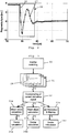
- FIG. 2 An example for switching transients of a current derivative sensor 6, 7 or 8 is depicted in Fig. 2 .
- the current derivative sensors 6, 7, 8 applied in this embodiment are of Rogowsky type.
- the primary design parameters number of turns n, coils area A, and coil material ( ⁇ r) influence both self- and mutual-inductance as well as the sensor bandwidth. It is thus possible to adapt such a sensor to the specific application of inverter fed operation.
- the bandwidth of the sensors 6, 7, 8 can thus be intentionally set below the dominant frequency of the switching transients to directly act as a noise filter.
- This settling time equals the minimum pulse duration necessary for each of at least two different switching states to perform the correct measurements and to extract the saliency information. Especially at low modulation indexes, it is obvious that a modification of the standard PWM is necessary to ensure this minimum pulse duration. If it is possible to avoid this blanking time during the switching transients, standard PWM can be used without modification in almost the whole operating range.
- the induction machine 2 was a 5.5kW machine with two poles, 36 stator slots and a rotor with 28 unskewed bars.
- the whole saliency detection scheme can be seen from Fig. 3 , starting with the machine excitation by changing the inverter switching state, block 30. Then the sensor signals - cf. transient curves at 31 - are sampled using for instance high speed A/D converters 9, 10, 11 ( Fig. 1 ) to establish oversampling - block 32 in Fig. 3 .
- the time duration selected for the further signal processing is limited to the switching transients as indicated by the two dashed vertical lines (window 28) in the time traces of the sensor output signals (curves 31).
- This oversampling is followed by different signal processing algorithms, cf. blocks 33a, 33b, and 33c in Fig. 3 , to calculate different characteristic signal parameters (e.g. mean value, mean slope and ⁇ modulation and filtering) that all contain the modulation of the saliencies.
- the calculated phase indicators are combined to a vector, according to blocks 34a, 34b, 34c.
- the signal processing may be done offline based on the values stored in a buffer. However, it is also possible that the whole sampling and preprocessing will be done e.g. in an FPGA (field programmable gate array). The sampling is realized at 10MHz.
- FPGA field programmable gate array
- the signal processing may be as follows.
- the measurement and sampling procedure offers the possibility to calculate not only the mean value during an observation window 28, but also to determine the slope of the sensor signal 26 what corresponds to the second time derivative of the phase current. As shown in Fig. 2 , the switching transition is clearly visible in the sensor signals for at least 6 ⁇ s.
- the window 28 length used for the further processing may thus varied between 2 ⁇ s and 14 ⁇ s to show its influence on the resulting saliency detection.
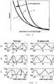
- Fig. 4 The influence of an observation window 28 variation on the variance of the signal obtained after the mean value calculation is shown in principle in Fig. 4 , for several oversampling rate values (curves 35, 36, 37), taken at the same position of the saliencies.
- the oversampling rate increases from right to left, i.e. from curve 35 to curve 37.
- the expected value changes with the window length due to the signal transients; it has turned out that even if the whole window lies within the switching transient ( ⁇ 8 ⁇ s), the variance is already quite low so that sufficiently exact detection results are obtained, and the results are the better the higher the oversampling rate.
- the slotting saliency of an unskewed machine may be chosen.
- the machine 2 can be operated without main flux at first.
- N is the number of rotor slots (e.g. 28 for the machine-under-test).
- the time derivative of the sensor signals (difference between a set of subsequent sampled di/dt-values) can be determined using a short and fast algorithm.
- the average values of the differences can be calculated using a moving window within the set of sampled values. Then the time trace of the average (mean) value is obtained what delivers an estimate of the sensor output slope superposed with the switching transients. Applying this algorithm leads to the results shown in Fig. 5 , line C ("mean slope").
- a very attractive alternative to fast sampling standard analog to digital converters is the usage of delta sigma converters, cf. also block 33c in Fig. 3 , as oversampling means 12 ( Fig. 1 ).
- the single-bit data transmission offers high robustness against EMI (electromagnetic interference).
- EMI electromagnetic interference
- the converter comprises a modulator and a filter.
- the modulator converts the analog signal into a digital data stream.
- a filter is used to increase the resolution and to reduce quantization noise what is also called noise shaping.
- the modulator consists of a set of integrators, a comparator and a single-bit digital-to-analog converter. The input signal of the modulator is passed through the integrators. Using the comparator, this signal is converted to a bit stream. This bit stream is passed through the digital-to-analog converter and fed back again to the integrator inputs where it is subtracted.
- the second stage of the delta-sigma conversion is a low pass filter.
- This filter removes the quantization noise, and by reducing the data rate (also called “decimation"), it increases the resolution.
- a combination of sincK and finite impulse response (FIR) filters is applied.
- the sincK filter establishes the first step of the decimation and has thus to operate at sampling frequency.
- the advantage of the sincK filter is that no digital multipliers are necessary what makes it ideal for hardware realization using e.g. a field programmable gate array (FPGA) .
- FPGA field programmable gate array
- the delta sigma modulator with the feed back has a more effective high pass behavior with respect to the quantization noise and low pass properties for the input signal than other oversampling methods.
- the decimation filter allows an increased resolution by realizing a moving average over a specific number of samples.
- this moving average can effectively be applied to filter also specific signal noise components introduced by the switching transition.
- Fig. 6 the sensor and modulator signals of a delta-sigma modulation are shown during a switching transition.
- the upper diagram depicts the time trace 26 of a di/dt sensor 6, 7 or 8 during the first 4 ⁇ s after the switching transition. This signal equals the input signal to the modulator.
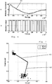
- a signal with low distortions is obtained, correlated to the steady state di/dt. Measurement results for mechanical standstill are depicted in Fig. 7 .
- the resulting saliency signal (slotting saliency position) is represented by the black (solid) phasor 41.
- the dots around the tip of this phasor 41 represent subsequent measurements for the same saliency (rotor) position.
- a second set of measurements is done at a different rotor position and using a 4.8 ⁇ s observation window (dashed phasor 42).
- a modulator running at 10MHz and a sinc3-filter with a decimation of 16 (corresponding observation window length equals 4.8ps) were used for the saliency detection.
- the accuracy is high enough to allow a clear identification of the slotting saliency and with a quality comparable to measurements taken in combination with standard current transducers and 50 ⁇ s (! pulse duration.
- the present method is based on an elimination of the switching transients from the sampled signals by using oversampling techniques. This elimination of course cannot be perfect, leading to a remaining influence of the fundamental wave. This influence can be identified, fed forward and then further reduced by applying standard compensation means.
- the oversampling techniques are applied to current derivative sensors.
- a time derivative is calculated using state of the art algorithms in the evaluation means 16. It enables an effective means of eliminating the distortion caused by the switching transients introduced by the inverter.
- the present invention may be applied in the case of sensorless speed control of ac machines, but also in other cases where a detection of the rotor position is wished.
- the invention may be applied to the detection of (beginning) defects in ac machines, as for instance when a rotor bar is beginning to break; or in cases of insulation faults (short-circuiting of turns of a winding); or bearing defects.
Landscapes
- Engineering & Computer Science (AREA)
- Power Engineering (AREA)
- Control Of Ac Motors In General (AREA)
Claims (15)
- Verfahren zum Verfolgen inhärenter Schenkeligkeiten von Wechselstrommaschinen (2), die einen Stator mit Wicklungen (3) und einen Rotor aufweisen, wobei Zeitableitungsänderungen des transienten Stroms (26) oder Änderungen des transienten Stroms aufgrund von an die Statorwicklungen angelegten Spannungsimpulsen abgefühlt werden und die abgefühlten Signale ausgewertet werden, um die Schenkeligkeiten zu verfolgen, dadurch gekennzeichnet, dass die abgefühlten Signale, mit überlagerten Schalttransienten, ausgewertet werden durch Anwenden von Überabtasten für die abgefühlten Signale mit einer Überabtastrate, die auf die Frequenz der Zeitableitungsänderungen des transienten Stroms oder der Änderungen des transienten Stroms bezogen ist, und durch Auswerten von Signalindikatoren, die dem Beharrungswert der Zeitableitung des Stroms entsprechen, wobei die Signalindikatoren Modulationen aufgrund der Schenkeligkeiten aufweisen.
- Verfahren nach Anspruch 1, dadurch gekennzeichnet, dass die Auswertung der abgetasteten Zeitableitungsänderungen des transienten Stroms oder der Änderungen des transienten Stroms auf ein eingeschränktes Beobachtungszeitfenster begrenzt ist.
- Verfahren nach Anspruch 2, dadurch gekennzeichnet, dass das Beobachtungszeitfenster auf der Basis der abgetasteten Werte in Kombination mit Steuerimpulsen angestoßen wird, die zeitlich auf die an die Statorwicklungen (3) angelegten Spannungsimpulse bezogen sind.
- Verfahren nach einem der Ansprüche 1 bis 3, dadurch gekennzeichnet, dass die Änderungen des transienten Stroms mittels eines Stromableitungssensors (6, 7, 8) abgefühlt werden.
- Verfahren nach einem der Ansprüche 1 bis 4, dadurch gekennzeichnet, dass die abgetasteten Sensorsignalwerte in Mittelwertberechnungsmodulen (18, 19, 20) ausgewertet werden.
- Verfahren nach Anspruch 5, dadurch gekennzeichnet, dass ein Mittelwert (33a) der Signalwerte berechnet wird.
- Verfahren nach Anspruch 5 oder 6, dadurch gekennzeichnet, dass ein mittlerer Steigungswert (33b) der Signalwerte berechnet wird.
- Verfahren nach einem der Ansprüche 5 bis 7, dadurch gekennzeichnet, dass die abgetasteten Sensorsignalwerte mittels eines Deltasignalkonverter- und -filtermoduls ausgewertet werden.
- System (1) zum Verfolgen inhärenter Schenkeligkeiten von Wechselstrommaschinen (2), die einen Stator mit Wicklungen (3) und einen Rotor aufweisen, wobei das System wenigstens einen Sensor (6, 7, 8) aufweist, der dazu ausgelegt ist, Zeitableitungsänderungen des transienten Stroms oder Änderungen des transienten Stroms aufgrund von an die Statorwicklungen angelegten Spannungsimpulsen abzufühlen, und Auswertemittel (16), die dazu ausgelegt sind, die abgefühlten Signale auszuwerten, um die Schenkeligkeiten zu verfolgen, gekennzeichnet durch Überabtastmittel (12), die dazu ausgelegt sind, die abgefühlten Signale, mit überlagerten Schalttransienten, mit einer Überabtastrate abzutasten, die auf die Frequenz der Zeitableitungsänderungen des transienten Stroms oder der Änderungen des transienten Stroms bezogen ist, und durch die Auswertemittel (16), die dazu ausgelegt sind, Signalindikatoren auszuwerten, die dem Beharrungswert der Zeitableitung des Stroms entsprechen, wobei die Signalindikatoren Modulationen aufgrund der Schenkeligkeiten aufweisen.
- System nach Anspruch 9, dadurch gekennzeichnet, dass die Auswertemittel (16) dazu ausgelegt sind, die Auswertung der abgetasteten Änderungen des transienten Stroms auf ein begrenztes Beobachtungszeitfenster (28) zu beschränken.
- System nach Anspruch 10, dadurch gekennzeichnet, dass das Beobachtungszeitfenster auf der Basis der abgetasteten Werte in Kombination mit Steuerimpulsen angestoßen wird, die zeitlich auf die an die Statorwicklungen angelegten Spannungsimpulse bezogen sind.
- System nach einem der Ansprüche 9 bis 11, dadurch gekennzeichnet, dass der wenigstens eine Sensor (6, 7, 8) ein Stromableitungssensor ist.
- System nach einem der Ansprüche 9 bis 12, dadurch gekennzeichnet, dass die Auswertemittel (16) Mittelwertberechnungsmodule (18, 19, 20) aufweisen.
- System nach einem der Ansprüche 9 bis 13, dadurch gekennzeichnet, dass die Überabtastmittel (12) wenigstens ein Deltasignalkonverter- und -filtermodul aufweisen.
- System nach einem der Ansprüche 9 bis 14, dadurch gekennzeichnet, dass die Überabtastmittel (12) wenigstens einen A/D-Wandler (9, 10, 11) aufweisen.
Priority Applications (2)
| Application Number | Priority Date | Filing Date | Title |
|---|---|---|---|
| EP10450114.3A EP2405570B1 (de) | 2010-07-07 | 2010-07-07 | Verfahren und System zur Verfolgung der innewohnenden Salienzen von Wechselstrommaschinen |
| PCT/EP2011/061502 WO2012004343A1 (en) | 2010-07-07 | 2011-07-07 | A method and system for tracking inherent saliencies of ac machines |
Applications Claiming Priority (1)
| Application Number | Priority Date | Filing Date | Title |
|---|---|---|---|
| EP10450114.3A EP2405570B1 (de) | 2010-07-07 | 2010-07-07 | Verfahren und System zur Verfolgung der innewohnenden Salienzen von Wechselstrommaschinen |
Publications (2)
| Publication Number | Publication Date |
|---|---|
| EP2405570A1 EP2405570A1 (de) | 2012-01-11 |
| EP2405570B1 true EP2405570B1 (de) | 2018-03-21 |
Family
ID=43530237
Family Applications (1)
| Application Number | Title | Priority Date | Filing Date |
|---|---|---|---|
| EP10450114.3A Not-in-force EP2405570B1 (de) | 2010-07-07 | 2010-07-07 | Verfahren und System zur Verfolgung der innewohnenden Salienzen von Wechselstrommaschinen |
Country Status (2)
| Country | Link |
|---|---|
| EP (1) | EP2405570B1 (de) |
| WO (1) | WO2012004343A1 (de) |
Families Citing this family (10)
| Publication number | Priority date | Publication date | Assignee | Title |
|---|---|---|---|---|
| AT511807B1 (de) * | 2011-08-01 | 2013-03-15 | Univ Wien Tech | Verfahren und vorrichtung zur online-erkennung einer zustandsverschlechterung einer isolierung in einer elektrischen maschine |
| JP6132948B1 (ja) * | 2016-03-29 | 2017-05-24 | 三菱電機株式会社 | モータ制御装置およびモータ制御方法 |
| DE102017210071A1 (de) * | 2017-06-14 | 2018-12-20 | Robert Bosch Gmbh | Verfahren zur Ermittlung von Phasenströmen einer mittels eines PWM-gesteuerten Wechselrichters gespeisten, rotierenden, mehrphasigen, elektrischen Maschine |
| GB2574416A (en) * | 2018-06-05 | 2019-12-11 | Bombardier Transp Gmbh | A method and an apparatus for determining a temperature of a rotor |
| GB2581187A (en) * | 2019-02-07 | 2020-08-12 | Stannah Stairlifts Ltd | Electric motor control |
| DE102019220169A1 (de) | 2019-12-19 | 2021-06-24 | Bombardier Transportation Gmbh | Antriebssystem für ein Fahrzeug, Verfahren zum Betreiben des Antriebssystems, sowie Fahrzeug mit Antriebssystem |
| CN111258303B (zh) * | 2020-02-18 | 2021-07-30 | 中国电子产品可靠性与环境试验研究所((工业和信息化部电子第五研究所)(中国赛宝实验室)) | 伺服系统故障检测方法、装置、计算机设备和存储介质 |
| DE102020212196A1 (de) | 2020-09-28 | 2022-03-31 | Volkswagen Aktiengesellschaft | Verfahren und Vorrichtung zum Überwachen eines elektrischen Antriebs |
| US11926880B2 (en) | 2021-04-21 | 2024-03-12 | General Electric Company | Fabrication method for a component having magnetic and non-magnetic dual phases |
| US11661646B2 (en) | 2021-04-21 | 2023-05-30 | General Electric Comapny | Dual phase magnetic material component and method of its formation |
Family Cites Families (2)
| Publication number | Priority date | Publication date | Assignee | Title |
|---|---|---|---|---|
| JP2003219690A (ja) * | 2002-01-24 | 2003-07-31 | Meidensha Corp | Pwmインバータの出力電流検出方式 |
| DK200200572A (da) * | 2002-04-17 | 2003-10-18 | Danfoss Drives As | Fremgangsmåde til måling af strøm i en motorstyring og motorstyring som bruger denne fremgangsmåde |
-
2010
- 2010-07-07 EP EP10450114.3A patent/EP2405570B1/de not_active Not-in-force
-
2011
- 2011-07-07 WO PCT/EP2011/061502 patent/WO2012004343A1/en not_active Ceased
Also Published As
| Publication number | Publication date |
|---|---|
| EP2405570A1 (de) | 2012-01-11 |
| WO2012004343A1 (en) | 2012-01-12 |
Similar Documents
| Publication | Publication Date | Title |
|---|---|---|
| EP2405570B1 (de) | Verfahren und System zur Verfolgung der innewohnenden Salienzen von Wechselstrommaschinen | |
| KR101041050B1 (ko) | 모터구동제어 | |
| Wang et al. | Rotor position estimation of PMSM in low-speed region and standstill using zero-voltage vector injection | |
| CN107786139B (zh) | 确定电机参数的系统和方法 | |
| KR102579496B1 (ko) | 표면 영구 자석 전기 기계의 초기 위치를 온라인 추정하기 위한 방법 및 장치 | |
| GB2455122A (en) | Control of electrical machines | |
| Landsmann et al. | Lowering injection amplitude in sensorless control by means of current oversampling | |
| JP6116538B2 (ja) | モータ制御装置 | |
| Setty et al. | Comparison of high frequency signal injection techniques for rotor position estimation at low speed to standstill of PMSM | |
| CA2887080A1 (en) | Systems and methods for rotor position determination | |
| Weber et al. | Increased signal-to-noise ratio of sensorless control using current oversampling | |
| Brosse et al. | Sensorless control of a SRM at low speeds and standstill based on signal power evaluation | |
| Nussbaumer et al. | Saliency tracking based sensorless control of AC machines exploiting inverter switching transients | |
| Staines et al. | Rotor position estimation for induction machines at zero and low frequency utilising zero sequence currents | |
| Hind et al. | Estimating current derivatives for sensorless motor drive applications | |
| Leidhold et al. | Improved method for higher dynamics in sensorless position detection | |
| KR101790380B1 (ko) | Pm 모터의 모터 상수 산출 방법 및 모터 상수 산출 장치 | |
| US6861966B2 (en) | Method for providing a digital current fluctuation signal | |
| JP2020524971A (ja) | Pwm制御方式のインバータによって給電される回転多相電気機器の相電流を決定する方法 | |
| Nussbaumer et al. | Using oversampling techniques to extract ac machine saliency information | |
| Ralev et al. | Accurate rotor position detection for low-speed operation of switched reluctance drives | |
| Ma et al. | FPGA based signal injection sensorless control of SMPMSM using Delta-Sigma A/D conversion | |
| Hua et al. | Sensorless control of surface mounted permanent magnetic machine using the standard space vector PWN | |
| Hammel et al. | High-resolution sensorless position estimation using delta-sigma-modulated current measurement | |
| Amhof et al. | Sensorless position estimation from PWM-induced transient excitation in induction machines |
Legal Events
| Date | Code | Title | Description |
|---|---|---|---|
| AK | Designated contracting states |
Kind code of ref document: A1 Designated state(s): AL AT BE BG CH CY CZ DE DK EE ES FI FR GB GR HR HU IE IS IT LI LT LU LV MC MK MT NL NO PL PT RO SE SI SK SM TR |
|
| AX | Request for extension of the european patent |
Extension state: BA ME RS |
|
| PUAI | Public reference made under article 153(3) epc to a published international application that has entered the european phase |
Free format text: ORIGINAL CODE: 0009012 |
|
| 17P | Request for examination filed |
Effective date: 20120705 |
|
| GRAP | Despatch of communication of intention to grant a patent |
Free format text: ORIGINAL CODE: EPIDOSNIGR1 |
|
| INTG | Intention to grant announced |
Effective date: 20171004 |
|
| GRAS | Grant fee paid |
Free format text: ORIGINAL CODE: EPIDOSNIGR3 |
|
| GRAA | (expected) grant |
Free format text: ORIGINAL CODE: 0009210 |
|
| AK | Designated contracting states |
Kind code of ref document: B1 Designated state(s): AL AT BE BG CH CY CZ DE DK EE ES FI FR GB GR HR HU IE IS IT LI LT LU LV MC MK MT NL NO PL PT RO SE SI SK SM TR |
|
| REG | Reference to a national code |
Ref country code: GB Ref legal event code: FG4D |
|
| REG | Reference to a national code |
Ref country code: CH Ref legal event code: EP |
|
| REG | Reference to a national code |
Ref country code: AT Ref legal event code: REF Ref document number: 982125 Country of ref document: AT Kind code of ref document: T Effective date: 20180415 |
|
| REG | Reference to a national code |
Ref country code: IE Ref legal event code: FG4D |
|
| REG | Reference to a national code |
Ref country code: DE Ref legal event code: R096 Ref document number: 602010049274 Country of ref document: DE |
|
| REG | Reference to a national code |
Ref country code: NL Ref legal event code: MP Effective date: 20180321 |
|
| PG25 | Lapsed in a contracting state [announced via postgrant information from national office to epo] |
Ref country code: NO Free format text: LAPSE BECAUSE OF FAILURE TO SUBMIT A TRANSLATION OF THE DESCRIPTION OR TO PAY THE FEE WITHIN THE PRESCRIBED TIME-LIMIT Effective date: 20180621 Ref country code: FI Free format text: LAPSE BECAUSE OF FAILURE TO SUBMIT A TRANSLATION OF THE DESCRIPTION OR TO PAY THE FEE WITHIN THE PRESCRIBED TIME-LIMIT Effective date: 20180321 Ref country code: HR Free format text: LAPSE BECAUSE OF FAILURE TO SUBMIT A TRANSLATION OF THE DESCRIPTION OR TO PAY THE FEE WITHIN THE PRESCRIBED TIME-LIMIT Effective date: 20180321 Ref country code: LT Free format text: LAPSE BECAUSE OF FAILURE TO SUBMIT A TRANSLATION OF THE DESCRIPTION OR TO PAY THE FEE WITHIN THE PRESCRIBED TIME-LIMIT Effective date: 20180321 Ref country code: CY Free format text: LAPSE BECAUSE OF FAILURE TO SUBMIT A TRANSLATION OF THE DESCRIPTION OR TO PAY THE FEE WITHIN THE PRESCRIBED TIME-LIMIT Effective date: 20180321 |
|
| REG | Reference to a national code |
Ref country code: LT Ref legal event code: MG4D |
|
| REG | Reference to a national code |
Ref country code: AT Ref legal event code: MK05 Ref document number: 982125 Country of ref document: AT Kind code of ref document: T Effective date: 20180321 |
|
| PG25 | Lapsed in a contracting state [announced via postgrant information from national office to epo] |
Ref country code: GR Free format text: LAPSE BECAUSE OF FAILURE TO SUBMIT A TRANSLATION OF THE DESCRIPTION OR TO PAY THE FEE WITHIN THE PRESCRIBED TIME-LIMIT Effective date: 20180622 Ref country code: SE Free format text: LAPSE BECAUSE OF FAILURE TO SUBMIT A TRANSLATION OF THE DESCRIPTION OR TO PAY THE FEE WITHIN THE PRESCRIBED TIME-LIMIT Effective date: 20180321 Ref country code: LV Free format text: LAPSE BECAUSE OF FAILURE TO SUBMIT A TRANSLATION OF THE DESCRIPTION OR TO PAY THE FEE WITHIN THE PRESCRIBED TIME-LIMIT Effective date: 20180321 Ref country code: BG Free format text: LAPSE BECAUSE OF FAILURE TO SUBMIT A TRANSLATION OF THE DESCRIPTION OR TO PAY THE FEE WITHIN THE PRESCRIBED TIME-LIMIT Effective date: 20180621 |
|
| PG25 | Lapsed in a contracting state [announced via postgrant information from national office to epo] |
Ref country code: NL Free format text: LAPSE BECAUSE OF FAILURE TO SUBMIT A TRANSLATION OF THE DESCRIPTION OR TO PAY THE FEE WITHIN THE PRESCRIBED TIME-LIMIT Effective date: 20180321 Ref country code: PL Free format text: LAPSE BECAUSE OF FAILURE TO SUBMIT A TRANSLATION OF THE DESCRIPTION OR TO PAY THE FEE WITHIN THE PRESCRIBED TIME-LIMIT Effective date: 20180321 Ref country code: ES Free format text: LAPSE BECAUSE OF FAILURE TO SUBMIT A TRANSLATION OF THE DESCRIPTION OR TO PAY THE FEE WITHIN THE PRESCRIBED TIME-LIMIT Effective date: 20180321 Ref country code: EE Free format text: LAPSE BECAUSE OF FAILURE TO SUBMIT A TRANSLATION OF THE DESCRIPTION OR TO PAY THE FEE WITHIN THE PRESCRIBED TIME-LIMIT Effective date: 20180321 Ref country code: IT Free format text: LAPSE BECAUSE OF FAILURE TO SUBMIT A TRANSLATION OF THE DESCRIPTION OR TO PAY THE FEE WITHIN THE PRESCRIBED TIME-LIMIT Effective date: 20180321 Ref country code: RO Free format text: LAPSE BECAUSE OF FAILURE TO SUBMIT A TRANSLATION OF THE DESCRIPTION OR TO PAY THE FEE WITHIN THE PRESCRIBED TIME-LIMIT Effective date: 20180321 Ref country code: AL Free format text: LAPSE BECAUSE OF FAILURE TO SUBMIT A TRANSLATION OF THE DESCRIPTION OR TO PAY THE FEE WITHIN THE PRESCRIBED TIME-LIMIT Effective date: 20180321 |
|
| PG25 | Lapsed in a contracting state [announced via postgrant information from national office to epo] |
Ref country code: CZ Free format text: LAPSE BECAUSE OF FAILURE TO SUBMIT A TRANSLATION OF THE DESCRIPTION OR TO PAY THE FEE WITHIN THE PRESCRIBED TIME-LIMIT Effective date: 20180321 Ref country code: SK Free format text: LAPSE BECAUSE OF FAILURE TO SUBMIT A TRANSLATION OF THE DESCRIPTION OR TO PAY THE FEE WITHIN THE PRESCRIBED TIME-LIMIT Effective date: 20180321 Ref country code: SM Free format text: LAPSE BECAUSE OF FAILURE TO SUBMIT A TRANSLATION OF THE DESCRIPTION OR TO PAY THE FEE WITHIN THE PRESCRIBED TIME-LIMIT Effective date: 20180321 Ref country code: AT Free format text: LAPSE BECAUSE OF FAILURE TO SUBMIT A TRANSLATION OF THE DESCRIPTION OR TO PAY THE FEE WITHIN THE PRESCRIBED TIME-LIMIT Effective date: 20180321 |
|
| PG25 | Lapsed in a contracting state [announced via postgrant information from national office to epo] |
Ref country code: PT Free format text: LAPSE BECAUSE OF FAILURE TO SUBMIT A TRANSLATION OF THE DESCRIPTION OR TO PAY THE FEE WITHIN THE PRESCRIBED TIME-LIMIT Effective date: 20180723 |
|
| REG | Reference to a national code |
Ref country code: DE Ref legal event code: R097 Ref document number: 602010049274 Country of ref document: DE |
|
| PLBE | No opposition filed within time limit |
Free format text: ORIGINAL CODE: 0009261 |
|
| STAA | Information on the status of an ep patent application or granted ep patent |
Free format text: STATUS: NO OPPOSITION FILED WITHIN TIME LIMIT |
|
| PG25 | Lapsed in a contracting state [announced via postgrant information from national office to epo] |
Ref country code: DK Free format text: LAPSE BECAUSE OF FAILURE TO SUBMIT A TRANSLATION OF THE DESCRIPTION OR TO PAY THE FEE WITHIN THE PRESCRIBED TIME-LIMIT Effective date: 20180321 |
|
| REG | Reference to a national code |
Ref country code: DE Ref legal event code: R119 Ref document number: 602010049274 Country of ref document: DE |
|
| 26N | No opposition filed |
Effective date: 20190102 |
|
| REG | Reference to a national code |
Ref country code: CH Ref legal event code: PL |
|
| GBPC | Gb: european patent ceased through non-payment of renewal fee |
Effective date: 20180707 |
|
| PG25 | Lapsed in a contracting state [announced via postgrant information from national office to epo] |
Ref country code: LU Free format text: LAPSE BECAUSE OF NON-PAYMENT OF DUE FEES Effective date: 20180707 Ref country code: MC Free format text: LAPSE BECAUSE OF FAILURE TO SUBMIT A TRANSLATION OF THE DESCRIPTION OR TO PAY THE FEE WITHIN THE PRESCRIBED TIME-LIMIT Effective date: 20180321 |
|
| REG | Reference to a national code |
Ref country code: BE Ref legal event code: MM Effective date: 20180731 |
|
| REG | Reference to a national code |
Ref country code: IE Ref legal event code: MM4A |
|
| PG25 | Lapsed in a contracting state [announced via postgrant information from national office to epo] |
Ref country code: LI Free format text: LAPSE BECAUSE OF NON-PAYMENT OF DUE FEES Effective date: 20180731 Ref country code: GB Free format text: LAPSE BECAUSE OF NON-PAYMENT OF DUE FEES Effective date: 20180707 Ref country code: IE Free format text: LAPSE BECAUSE OF NON-PAYMENT OF DUE FEES Effective date: 20180707 Ref country code: FR Free format text: LAPSE BECAUSE OF NON-PAYMENT OF DUE FEES Effective date: 20180731 Ref country code: CH Free format text: LAPSE BECAUSE OF NON-PAYMENT OF DUE FEES Effective date: 20180731 Ref country code: DE Free format text: LAPSE BECAUSE OF NON-PAYMENT OF DUE FEES Effective date: 20190201 |
|
| PG25 | Lapsed in a contracting state [announced via postgrant information from national office to epo] |
Ref country code: SI Free format text: LAPSE BECAUSE OF FAILURE TO SUBMIT A TRANSLATION OF THE DESCRIPTION OR TO PAY THE FEE WITHIN THE PRESCRIBED TIME-LIMIT Effective date: 20180321 Ref country code: BE Free format text: LAPSE BECAUSE OF NON-PAYMENT OF DUE FEES Effective date: 20180731 |
|
| PG25 | Lapsed in a contracting state [announced via postgrant information from national office to epo] |
Ref country code: MT Free format text: LAPSE BECAUSE OF NON-PAYMENT OF DUE FEES Effective date: 20180707 |
|
| PG25 | Lapsed in a contracting state [announced via postgrant information from national office to epo] |
Ref country code: TR Free format text: LAPSE BECAUSE OF FAILURE TO SUBMIT A TRANSLATION OF THE DESCRIPTION OR TO PAY THE FEE WITHIN THE PRESCRIBED TIME-LIMIT Effective date: 20180321 |
|
| PG25 | Lapsed in a contracting state [announced via postgrant information from national office to epo] |
Ref country code: HU Free format text: LAPSE BECAUSE OF FAILURE TO SUBMIT A TRANSLATION OF THE DESCRIPTION OR TO PAY THE FEE WITHIN THE PRESCRIBED TIME-LIMIT; INVALID AB INITIO Effective date: 20100707 |
|
| PG25 | Lapsed in a contracting state [announced via postgrant information from national office to epo] |
Ref country code: MK Free format text: LAPSE BECAUSE OF NON-PAYMENT OF DUE FEES Effective date: 20180321 |
|
| PG25 | Lapsed in a contracting state [announced via postgrant information from national office to epo] |
Ref country code: IS Free format text: LAPSE BECAUSE OF FAILURE TO SUBMIT A TRANSLATION OF THE DESCRIPTION OR TO PAY THE FEE WITHIN THE PRESCRIBED TIME-LIMIT Effective date: 20180721 |