EP2405570B1 - A method and system for tracking inherent saliencies of ac machines - Google Patents
A method and system for tracking inherent saliencies of ac machines Download PDFInfo
- Publication number
- EP2405570B1 EP2405570B1 EP10450114.3A EP10450114A EP2405570B1 EP 2405570 B1 EP2405570 B1 EP 2405570B1 EP 10450114 A EP10450114 A EP 10450114A EP 2405570 B1 EP2405570 B1 EP 2405570B1
- Authority
- EP
- European Patent Office
- Prior art keywords
- transient current
- signal
- saliencies
- sensor
- oversampling
- Prior art date
- Legal status (The legal status is an assumption and is not a legal conclusion. Google has not performed a legal analysis and makes no representation as to the accuracy of the status listed.)
- Not-in-force
Links
- 238000000034 method Methods 0.000 title claims description 39
- 230000001052 transient effect Effects 0.000 claims description 33
- 238000011156 evaluation Methods 0.000 claims description 16
- 238000004804 winding Methods 0.000 claims description 15
- 238000004364 calculation method Methods 0.000 claims description 10
- 230000001960 triggered effect Effects 0.000 claims description 4
- 238000005259 measurement Methods 0.000 description 30
- 238000005070 sampling Methods 0.000 description 19
- 230000007704 transition Effects 0.000 description 13
- 238000006243 chemical reaction Methods 0.000 description 12
- 230000006698 induction Effects 0.000 description 12
- 238000012545 processing Methods 0.000 description 11
- 230000005284 excitation Effects 0.000 description 10
- 230000000875 corresponding effect Effects 0.000 description 9
- 230000004907 flux Effects 0.000 description 9
- 238000001514 detection method Methods 0.000 description 8
- 238000012360 testing method Methods 0.000 description 8
- 238000010586 diagram Methods 0.000 description 7
- 238000002347 injection Methods 0.000 description 6
- 239000007924 injection Substances 0.000 description 6
- 230000010354 integration Effects 0.000 description 6
- 230000004044 response Effects 0.000 description 6
- 238000001914 filtration Methods 0.000 description 5
- 230000008030 elimination Effects 0.000 description 4
- 238000003379 elimination reaction Methods 0.000 description 4
- 238000013139 quantization Methods 0.000 description 4
- 230000008859 change Effects 0.000 description 3
- 238000000605 extraction Methods 0.000 description 3
- 238000012986 modification Methods 0.000 description 3
- 230000004048 modification Effects 0.000 description 3
- 239000003990 capacitor Substances 0.000 description 2
- 238000007796 conventional method Methods 0.000 description 2
- 230000007547 defect Effects 0.000 description 2
- 230000000694 effects Effects 0.000 description 2
- 239000000463 material Substances 0.000 description 2
- 238000001208 nuclear magnetic resonance pulse sequence Methods 0.000 description 2
- 230000003071 parasitic effect Effects 0.000 description 2
- 239000007787 solid Substances 0.000 description 2
- UXUFTKZYJYGMGO-CMCWBKRRSA-N (2s,3s,4r,5r)-5-[6-amino-2-[2-[4-[3-(2-aminoethylamino)-3-oxopropyl]phenyl]ethylamino]purin-9-yl]-n-ethyl-3,4-dihydroxyoxolane-2-carboxamide Chemical compound O[C@@H]1[C@H](O)[C@@H](C(=O)NCC)O[C@H]1N1C2=NC(NCCC=3C=CC(CCC(=O)NCCN)=CC=3)=NC(N)=C2N=C1 UXUFTKZYJYGMGO-CMCWBKRRSA-N 0.000 description 1
- 230000005534 acoustic noise Effects 0.000 description 1
- 238000004458 analytical method Methods 0.000 description 1
- 230000008901 benefit Effects 0.000 description 1
- 230000005540 biological transmission Effects 0.000 description 1
- 238000004891 communication Methods 0.000 description 1
- 238000010276 construction Methods 0.000 description 1
- 230000002596 correlated effect Effects 0.000 description 1
- 230000003247 decreasing effect Effects 0.000 description 1
- 230000001419 dependent effect Effects 0.000 description 1
- 238000013461 design Methods 0.000 description 1
- 238000009413 insulation Methods 0.000 description 1
- 230000003993 interaction Effects 0.000 description 1
- 238000000691 measurement method Methods 0.000 description 1
- 230000010355 oscillation Effects 0.000 description 1
- 238000007781 pre-processing Methods 0.000 description 1
- 230000008569 process Effects 0.000 description 1
- 238000003672 processing method Methods 0.000 description 1
- 238000011160 research Methods 0.000 description 1
- 230000035945 sensitivity Effects 0.000 description 1
- 238000007493 shaping process Methods 0.000 description 1
- 230000001629 suppression Effects 0.000 description 1
- 230000001360 synchronised effect Effects 0.000 description 1
Images

Classifications
-
- H—ELECTRICITY
- H02—GENERATION; CONVERSION OR DISTRIBUTION OF ELECTRIC POWER
- H02P—CONTROL OR REGULATION OF ELECTRIC MOTORS, ELECTRIC GENERATORS OR DYNAMO-ELECTRIC CONVERTERS; CONTROLLING TRANSFORMERS, REACTORS OR CHOKE COILS
- H02P6/00—Arrangements for controlling synchronous motors or other dynamo-electric motors using electronic commutation dependent on the rotor position; Electronic commutators therefor
- H02P6/14—Electronic commutators
- H02P6/16—Circuit arrangements for detecting position
- H02P6/18—Circuit arrangements for detecting position without separate position detecting elements
- H02P6/185—Circuit arrangements for detecting position without separate position detecting elements using inductance sensing, e.g. pulse excitation
-
- H—ELECTRICITY
- H02—GENERATION; CONVERSION OR DISTRIBUTION OF ELECTRIC POWER
- H02P—CONTROL OR REGULATION OF ELECTRIC MOTORS, ELECTRIC GENERATORS OR DYNAMO-ELECTRIC CONVERTERS; CONTROLLING TRANSFORMERS, REACTORS OR CHOKE COILS
- H02P6/00—Arrangements for controlling synchronous motors or other dynamo-electric motors using electronic commutation dependent on the rotor position; Electronic commutators therefor
- H02P6/14—Electronic commutators
- H02P6/16—Circuit arrangements for detecting position
- H02P6/18—Circuit arrangements for detecting position without separate position detecting elements
- H02P6/183—Circuit arrangements for detecting position without separate position detecting elements using an injected high frequency signal
-
- H—ELECTRICITY
- H02—GENERATION; CONVERSION OR DISTRIBUTION OF ELECTRIC POWER
- H02P—CONTROL OR REGULATION OF ELECTRIC MOTORS, ELECTRIC GENERATORS OR DYNAMO-ELECTRIC CONVERTERS; CONTROLLING TRANSFORMERS, REACTORS OR CHOKE COILS
- H02P2203/00—Indexing scheme relating to controlling arrangements characterised by the means for detecting the position of the rotor
- H02P2203/11—Determination or estimation of the rotor position or other motor parameters based on the analysis of high-frequency signals
Definitions
- the present invention refers to a method for tracking inherent saliencies of ac machines comprising a stator with windings and a rotor, wherein transient current time derivative changes or transient current changes due to voltage pulses applied to the stator windings are sensed, and the sensed signals are evaluated to track the saliencies; as well as to a system for tracking inherent saliencies of ac machines comprising a stator with windings and a rotor, said system comprising at least one sensor arranged to sense transient current time derivative changes or transient current changes due to voltage pulses applied to the stator windings, and evaluation means arranged to evaluate the sensed signals, to track the saliencies; according to the preambles of the independent claims.
- a continuous "injection" of a high frequency carrier signal (usually voltage) superposed to the fundamental wave is applied; then the machine response at this specific frequency is measured and evaluated; cf. for instance Degner et al., "Position Estimation in Induction Machines Utilizing Rotor Bar Slot Harmonics and Carrier Frequency Signal Injection", IEEE Trans. on Ind. Appl., Vol. 36 (3) (2000), pp. 736-742 ; or Teske et al., "Analysis and Suppression of High Frequency Inverter Modulation on Sensorless Position Controlled Induction Machine Drives", IEEE Trans. on Ind. Appl., Vol. 39 (1) (2003), pp. 10-18 .
- Special care has to be taken for the inverter interlock dead time that influences the injected hf component at every sector crossing. This way of injecting a test signal has to be continuously done, and thus an integration into the fundamental wave excitation is not possible.
- the second possible measurement principle is to use an excitation of the machine with voltage pulses and to measure the current step response; cf. for instance Schroedl, "Sensorless Control of Ac Machines at Low Speed and Standstill Based on the INFORM Method", Proceedings of 31st IAS Annual Meeting San Diego, Vol. 1 (1996), pp. 270-277 ; or Holtz et al., "Elimination of Saturation Effects in Sensorless Position Controlled Induction Motors", Proceedings of IEEE Industry Applications Annual Meeting, Vol. 3 (2002): pp. 1695-1702 .
- the voltage pulses are realized by changing the switching state of the inverter associated with the machine.
- the corresponding current responses can directly be used for the saliency measurement, compare e.g. Wolbank et al., "A modified PWM scheme in order to obtain spatial information of ac machines without mechanical sensor", Proc. IEEE Applied Power Electronics Conference, APEC (2002): pp. 310-315 .
- An integration of fundamental wave excitation and pulse voltage injection (test signals) is thus theoretically possible. The practical limits of this integration can be found in the measurement setup.
- a set of two measurements is necessary, taking the current difference at two time instants. More in detail, the current derivative di/dt is approximated by taking the difference ⁇ i of two current values during a specific time interval ⁇ T.
- the value of the minimum pulse duration is determined by the time necessary for the switching transients to settle plus the time that is determined by the sensor signal resolution.
- the current difference ⁇ i between the two current values must be high enough to allow also an accurate measurement of the modulation of the current difference caused by the saliencies. This modulation is in the range of a few percent of the fundamental wave when considering induction machines.
- the minimum time of a single pulse is in the range of 30 ⁇ s to 60 ⁇ s.
- the duration of the set of the two different active switching states necessary is thus in the order of at least 60 ⁇ s to 120 ⁇ s.
- a usual PWM period amounts about 100 ⁇ s.
- the switching sequence of the PWM can theoretically be used to extract the saliency information, one practical limit exists for all these methods: It is the minimum duration necessary for the current sensors to settle their output values after the so-called "signal ringing" due to parasitic effects caused by the steep voltage change. Before these switching transients weaken a sampling of the currents or their derivatives is not practical. Thus the switching sequence of the standard PWM has to be modified at least during each sector transition when the duration of one of the active switching states gets too short for a proper measurement.
- the present invention provides to extract the saliency information using the switching transients and applying oversampling, and therewith avoids the above mentioned measurement problem of the prior art by directly evaluating the sensor signals with the switching transients superposed. In most applications, the measurement procedure can be finished even before currently applied methods can start the sampling of the sensors.
- oversampling rates in the order of at least about 5 times, for instance about 10 times, the frequency of the transient current changes (which can be determined a priori for each respective machine in a test); in particular, the oversampling rate may be in the order of at least about 10MHz (in principle, according to the Nyquist-Shan-non theorem, the sampling frequency f sampling is higher than twice the maximum frequency f max of the sampled signal, and for oversampling, at least an additional factor 2 is chosen, that is f oversampling > 4 f max .
- the observation time window is triggered by control pulses which are timely related to the voltage pulses applied to the stator windings.
- the sampled sensor signal values are evaluated in mean value calculation modules.
- mean value calculation modules simply a mean value of the signal values and/or a mean slope value of the signal values may be calculated.
- observation time window is triggered by control pulses which are timely related to the voltage pulses applied to the stator windings.
- the evaluation means comprise a delta signal converter and filter module.
- an according A/D (analog/digital) converter having a corresponding cycle time may be used.
- a delta signal converter and filter module may be used.
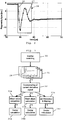
- the shown system 1 is associated with a usual induction machine 2 (ac machine) which includes a stator having windings (one being shown schematically at 3) and a rotor (not shown).
- ac machine which includes a stator having windings (one being shown schematically at 3) and a rotor (not shown).
- the machine 2 is e.g. a 3 phase ac machine, and an inverter 4 with a dc link capacitor 5 is connected to the three phase terminals of the machine 2.
- Each phase current is measured by a current derivative sensor 6, 7 and 8. Instead thereof, it would for instance also be possible to arrange one single sensor in the link circuit, between the link capacitor 5 and the inverter 4.
- the sensor signals are converted by respective analog to digital (A/D) converters 9, 10 and 11 with a high sampling rate to ensure oversampling of the switching transition. Accordingly, in this case, oversampling means 12 are formed by A/D converters 9, 10, 11.
- the sampled signals are then transferred to respective trigger/observation window elements 13, 14 and 15 which belong to evaluation means 16.
- the trigger instant is determined by combining switching commands obtained from a pulse width modulation unit 17 and the sampled sensor values. Only the sampled values lying within the respective observation windows, starting from the trigger instant, are transferred to respective mean value calculation means (blocks) 18, 19 and 20 which belong to the evaluation means 16, too.
- the three mean values of the three phase sensors 6, 7, 8 during the observation window are combined in a vector calculation block 21 (which again is a part of the evaluation means 16) to a space vector thus removing any offset value or zero sequence component.
- This signal is transferred to a saliency detection block 22 where, for instance in the case of the slotting saliency, the incremental rotor position information is calculated and superposed other saliencies, if any, may be removed, as is known per se.
- the necessary inverter output voltage to follow the external reference value inputted at 24 is determined based on the external reference value (input 24) and the calculated rotor position (input 25). It may be mentioned here that in the present drawing, a usual basis current control of the control block 23 has been left out to render the drawing not too complicated.
- FIG. 2 An example for switching transients of a current derivative sensor 6, 7 or 8 is depicted in Fig. 2 .
- the current derivative sensors 6, 7, 8 applied in this embodiment are of Rogowsky type.
- the primary design parameters number of turns n, coils area A, and coil material ( ⁇ r) influence both self- and mutual-inductance as well as the sensor bandwidth. It is thus possible to adapt such a sensor to the specific application of inverter fed operation.
- the bandwidth of the sensors 6, 7, 8 can thus be intentionally set below the dominant frequency of the switching transients to directly act as a noise filter.
- This settling time equals the minimum pulse duration necessary for each of at least two different switching states to perform the correct measurements and to extract the saliency information. Especially at low modulation indexes, it is obvious that a modification of the standard PWM is necessary to ensure this minimum pulse duration. If it is possible to avoid this blanking time during the switching transients, standard PWM can be used without modification in almost the whole operating range.
- the induction machine 2 was a 5.5kW machine with two poles, 36 stator slots and a rotor with 28 unskewed bars.
- the whole saliency detection scheme can be seen from Fig. 3 , starting with the machine excitation by changing the inverter switching state, block 30. Then the sensor signals - cf. transient curves at 31 - are sampled using for instance high speed A/D converters 9, 10, 11 ( Fig. 1 ) to establish oversampling - block 32 in Fig. 3 .
- the time duration selected for the further signal processing is limited to the switching transients as indicated by the two dashed vertical lines (window 28) in the time traces of the sensor output signals (curves 31).
- This oversampling is followed by different signal processing algorithms, cf. blocks 33a, 33b, and 33c in Fig. 3 , to calculate different characteristic signal parameters (e.g. mean value, mean slope and ⁇ modulation and filtering) that all contain the modulation of the saliencies.
- the calculated phase indicators are combined to a vector, according to blocks 34a, 34b, 34c.
- the signal processing may be done offline based on the values stored in a buffer. However, it is also possible that the whole sampling and preprocessing will be done e.g. in an FPGA (field programmable gate array). The sampling is realized at 10MHz.
- FPGA field programmable gate array
- the signal processing may be as follows.
- the measurement and sampling procedure offers the possibility to calculate not only the mean value during an observation window 28, but also to determine the slope of the sensor signal 26 what corresponds to the second time derivative of the phase current. As shown in Fig. 2 , the switching transition is clearly visible in the sensor signals for at least 6 ⁇ s.
- the window 28 length used for the further processing may thus varied between 2 ⁇ s and 14 ⁇ s to show its influence on the resulting saliency detection.
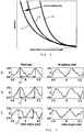
- Fig. 4 The influence of an observation window 28 variation on the variance of the signal obtained after the mean value calculation is shown in principle in Fig. 4 , for several oversampling rate values (curves 35, 36, 37), taken at the same position of the saliencies.
- the oversampling rate increases from right to left, i.e. from curve 35 to curve 37.
- the expected value changes with the window length due to the signal transients; it has turned out that even if the whole window lies within the switching transient ( ⁇ 8 ⁇ s), the variance is already quite low so that sufficiently exact detection results are obtained, and the results are the better the higher the oversampling rate.
- the slotting saliency of an unskewed machine may be chosen.
- the machine 2 can be operated without main flux at first.
- N is the number of rotor slots (e.g. 28 for the machine-under-test).
- the time derivative of the sensor signals (difference between a set of subsequent sampled di/dt-values) can be determined using a short and fast algorithm.
- the average values of the differences can be calculated using a moving window within the set of sampled values. Then the time trace of the average (mean) value is obtained what delivers an estimate of the sensor output slope superposed with the switching transients. Applying this algorithm leads to the results shown in Fig. 5 , line C ("mean slope").
- a very attractive alternative to fast sampling standard analog to digital converters is the usage of delta sigma converters, cf. also block 33c in Fig. 3 , as oversampling means 12 ( Fig. 1 ).
- the single-bit data transmission offers high robustness against EMI (electromagnetic interference).
- EMI electromagnetic interference
- the converter comprises a modulator and a filter.
- the modulator converts the analog signal into a digital data stream.
- a filter is used to increase the resolution and to reduce quantization noise what is also called noise shaping.
- the modulator consists of a set of integrators, a comparator and a single-bit digital-to-analog converter. The input signal of the modulator is passed through the integrators. Using the comparator, this signal is converted to a bit stream. This bit stream is passed through the digital-to-analog converter and fed back again to the integrator inputs where it is subtracted.
- the second stage of the delta-sigma conversion is a low pass filter.
- This filter removes the quantization noise, and by reducing the data rate (also called “decimation"), it increases the resolution.
- a combination of sincK and finite impulse response (FIR) filters is applied.
- the sincK filter establishes the first step of the decimation and has thus to operate at sampling frequency.
- the advantage of the sincK filter is that no digital multipliers are necessary what makes it ideal for hardware realization using e.g. a field programmable gate array (FPGA) .
- FPGA field programmable gate array
- the delta sigma modulator with the feed back has a more effective high pass behavior with respect to the quantization noise and low pass properties for the input signal than other oversampling methods.
- the decimation filter allows an increased resolution by realizing a moving average over a specific number of samples.
- this moving average can effectively be applied to filter also specific signal noise components introduced by the switching transition.
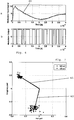
- Fig. 6 the sensor and modulator signals of a delta-sigma modulation are shown during a switching transition.
- the upper diagram depicts the time trace 26 of a di/dt sensor 6, 7 or 8 during the first 4 ⁇ s after the switching transition. This signal equals the input signal to the modulator.
- a signal with low distortions is obtained, correlated to the steady state di/dt. Measurement results for mechanical standstill are depicted in Fig. 7 .
- the resulting saliency signal (slotting saliency position) is represented by the black (solid) phasor 41.
- the dots around the tip of this phasor 41 represent subsequent measurements for the same saliency (rotor) position.
- a second set of measurements is done at a different rotor position and using a 4.8 ⁇ s observation window (dashed phasor 42).
- a modulator running at 10MHz and a sinc3-filter with a decimation of 16 (corresponding observation window length equals 4.8ps) were used for the saliency detection.
- the accuracy is high enough to allow a clear identification of the slotting saliency and with a quality comparable to measurements taken in combination with standard current transducers and 50 ⁇ s (! pulse duration.
- the present method is based on an elimination of the switching transients from the sampled signals by using oversampling techniques. This elimination of course cannot be perfect, leading to a remaining influence of the fundamental wave. This influence can be identified, fed forward and then further reduced by applying standard compensation means.
- the oversampling techniques are applied to current derivative sensors.
- a time derivative is calculated using state of the art algorithms in the evaluation means 16. It enables an effective means of eliminating the distortion caused by the switching transients introduced by the inverter.
- the present invention may be applied in the case of sensorless speed control of ac machines, but also in other cases where a detection of the rotor position is wished.
- the invention may be applied to the detection of (beginning) defects in ac machines, as for instance when a rotor bar is beginning to break; or in cases of insulation faults (short-circuiting of turns of a winding); or bearing defects.
Landscapes
- Engineering & Computer Science (AREA)
- Power Engineering (AREA)
- Control Of Ac Motors In General (AREA)
Description
- The present invention refers to a method for tracking inherent saliencies of ac machines comprising a stator with windings and a rotor, wherein transient current time derivative changes or transient current changes due to voltage pulses applied to the stator windings are sensed, and the sensed signals are evaluated to track the saliencies; as well as to a system for tracking inherent saliencies of ac machines comprising a stator with windings and a rotor, said system comprising at least one sensor arranged to sense transient current time derivative changes or transient current changes due to voltage pulses applied to the stator windings, and evaluation means arranged to evaluate the sensed signals, to track the saliencies; according to the preambles of the independent claims.
- Usually, modern electrical machines are designed and manufactured symmetrical; nevertheless, there are always some inherent saliencies present. These saliencies are usually not visible in the fundamental wave behavior of the machine; however, when looking at the high frequency or transient inductance there is a modulation detectable that can be exploited for speed sensorless control. Examples for main saliencies are the stator/rotor slotting saliency, the rotor (material, shape etc.) anisotropy saliency, and/or the main flux saturation saliency.
- These saliencies influence the phase values of the high frequency or transient stator inductances. Their modulations thus correspond to the movement of the rotor or flux position. The mentioned saliencies are inherent, sometimes specifically constructed, and their magnitudes are very small when compared to the fundamental wave (usually clear below 10% considering induction machines).
- To identify the phase values of the hf stator inductance, according to the prior art, two principles of measurement sequences have been suggested.
- According to a first measurement setup, a continuous "injection" of a high frequency carrier signal (usually voltage) superposed to the fundamental wave is applied; then the machine response at this specific frequency is measured and evaluated; cf. for instance Degner et al., "Position Estimation in Induction Machines Utilizing Rotor Bar Slot Harmonics and Carrier Frequency Signal Injection", IEEE Trans. on Ind. Appl., Vol. 36 (3) (2000), pp. 736-742; or Teske et al., "Analysis and Suppression of High Frequency Inverter Modulation on Sensorless Position Controlled Induction Machine Drives", IEEE Trans. on Ind. Appl., Vol. 39 (1) (2003), pp. 10-18. Special care has to be taken for the inverter interlock dead time that influences the injected hf component at every sector crossing. This way of injecting a test signal has to be continuously done, and thus an integration into the fundamental wave excitation is not possible.
- The second possible measurement principle is to use an excitation of the machine with voltage pulses and to measure the current step response; cf. for instance Schroedl, "Sensorless Control of Ac Machines at Low Speed and Standstill Based on the INFORM Method", Proceedings of 31st IAS Annual Meeting San Diego, Vol. 1 (1996), pp. 270-277; or Holtz et al., "Elimination of Saturation Effects in Sensorless Position Controlled Induction Motors", Proceedings of IEEE Industry Applications Annual Meeting, Vol. 3 (2002): pp. 1695-1702. The voltage pulses are realized by changing the switching state of the inverter associated with the machine. As the voltage step response is influenced by the transient inductance, the stator resistance, the back emf (electromagnetic force), and the dc link voltage, a set of at least two different active inverter switching states has to be applied to extract the value of the transient inductance. This pulse sequence has to be applied each time a measurement of the saliency position has to be taken. Bartolo et al., "Flux position estimation using current derivatives for the sensorless control of AC machines", IEEE (2008): 1468-1473 describes a method for tracking inherent saliences of ac machines. To establish the fundamental wave excitation of the machine, a usual PWM (pulse width modulation) of the machine is continuously applying voltage pulses to the machine. In some operating states the corresponding current responses can directly be used for the saliency measurement, compare e.g. Wolbank et al., "A modified PWM scheme in order to obtain spatial information of ac machines without mechanical sensor", Proc. IEEE Applied Power Electronics Conference, APEC (2002): pp. 310-315. An integration of fundamental wave excitation and pulse voltage injection (test signals) is thus theoretically possible. The practical limits of this integration can be found in the measurement setup. To identify the current derivative using standard industrial current sensors, a set of two measurements is necessary, taking the current difference at two time instants. More in detail, the current derivative di/dt is approximated by taking the difference Δi of two current values during a specific time interval ΔT. The value of the minimum pulse duration is determined by the time necessary for the switching transients to settle plus the time that is determined by the sensor signal resolution. The current difference Δi between the two current values must be high enough to allow also an accurate measurement of the modulation of the current difference caused by the saliencies. This modulation is in the range of a few percent of the fundamental wave when considering induction machines. In practical measurements, the minimum time of a single pulse is in the range of 30µs to 60µs. The duration of the set of the two different active switching states necessary is thus in the order of at least 60µs to 120µs. On the other hand, a usual PWM period amounts about 100µs.
- Accordingly, to reduce this minimum necessary duration, in Wolbank et al., "Prediction and measurements of a current derivative sensor response for voltage pulses applied to induction machines", Journal of Applied Physics, Vol. 93 (10) (2003): pp. 6656-6658, the application of current derivative sensors has been proposed. As only one sample is then necessary, the only limitation is imposed by the settling time of the sensor signals after the switching transients. The minimum time duration of a single pulse is then in the range of 10µs or some few 10µs. As long as the active pulse durations of the fundamental wave PWM are above this minimum value, an integration of the test signal is possible.
- From James Borg Bartolo et al., "Flux Position Estimation using Current Derivatives for the Sensorless Control of AC Machines", Communications, Control and Signal Processing, 2008 ISCCSP 2008.3rd International Symposium on IEEE, PISCATAWAY, NJ USA, 12 March 2008, pages 1468-1473, it is known in connection with saliency tracking in AC machines to use pulse type injection for the extraction of a rotor or flux position signal. The saliency is tracked by measuring the current derivative resulting from voltage test application. However, more in detail, it is provided here that the measurement of the sensor signals is carried out only after a rather long delay time, for instance 10.5 psec or 20 psec; this delay has been introduced to allow for the current derivative signal to settle to a constant value. Namely, it is stated that the main criterion of performance assessment is the settling time required for a stable derivative value to be sampled.
- Then, from the
WO 03/087855 A1
Finally, in Markus A. Vogelsberger et al., "Using PWM-Induced Transient Excitation and Advanced Signal Processing for Zero-Speed Sensorless Control of AC Machines" of the IEEE Transaction on Industrial Electronics, January 2010, Vol. 57 (1), page 365-374 again signal-injection methods are disclosed where current derivatives are measured, and where it is pointed to that in the case that current derivatives are measured during a zero voltage vector, the signal magnitude is very low which leads to an increased sensitivity to noise. In the following, specific algorithms are referred to, as in particular the so called RANSAC algorithm, to solve the location-determination problem. - Besides this, an important aspect in view of the application of the present invention should be mentioned, namely the sensorless speed control of ac machines. Such sensorless control has been developed in the past decades from an academic research topic to wide industrial application. The industrially applied techniques rely on integration of the machines back-emf to determine the flux position, to deliver excellent performance in the medium and high speed/frequency range. With decreasing fundamental frequency, the influence of parameter variations increases, this leading to reduced accuracy. Finally, when operated at zero frequency, no stable operation is possible due to the lack of feedback for the integration, as is for instance described in Holtz et al., "Sensorless Control of Induction Motor Drives", Proceedings of IEEE, Vol. 90 (8) (2002). In this operating range, methods have to be applied that are able to track the inherent saliencies of the machine.
- These saliencies are not visible in the frequency range of the fundamental wave, they can, however, be measured when considering the high frequency or transient electrical properties of the machine, as mentioned above. As explained, methods to extract saliency information so far are either based on the hf (high frequency) properties using an additional excitation of the machine ("signal injection") by rotating or pulsating carrier signals, or on the transient current change due to voltage pulses imposed by switching patterns.
- As the injected signal also has side effects in terms of acoustic noise emission, maximum inverter output voltage, and inverter switching frequency, efforts have been made to integrate especially the transient excitation sequences into the fundamental wave PWM, compare e.g. the article of Wolbank et al. referred to above.
- Though the switching sequence of the PWM can theoretically be used to extract the saliency information, one practical limit exists for all these methods: It is the minimum duration necessary for the current sensors to settle their output values after the so-called "signal ringing" due to parasitic effects caused by the steep voltage change. Before these switching transients weaken a sampling of the currents or their derivatives is not practical. Thus the switching sequence of the standard PWM has to be modified at least during each sector transition when the duration of one of the active switching states gets too short for a proper measurement.
- Accordingly, it is an object of this invention to provide a method and a system as mentioned above where substantially shorter time measurement intervals are rendered possible to yet obtain a reliable evaluation of the transient current changes, in particular time durations clearly below lOps, that is e.g. one order shorter when compared with the prior art.
- Accordingly, the above problem is solved by a method and by a system as defined in the independent claims.
- Preferred embodiments of the invention are defined in the dependent claims.
- In short, the present invention provides to extract the saliency information using the switching transients and applying oversampling, and therewith avoids the above mentioned measurement problem of the prior art by directly evaluating the sensor signals with the switching transients superposed. In most applications, the measurement procedure can be finished even before currently applied methods can start the sampling of the sensors.
- According to a preferred technique, oversampling rates in the order of at least about 5 times, for instance about 10 times, the frequency of the transient current changes (which can be determined a priori for each respective machine in a test); in particular, the oversampling rate may be in the order of at least about 10MHz (in principle, according to the Nyquist-Shan-non theorem, the sampling frequency fsampling is higher than twice the maximum frequency f max of the sampled signal, and for oversampling, at least an
additional factor 2 is chosen, that is foversampling > 4f max. - Furthermore, to reduce the evaluation actions, it is preferred to restrict a priori the evaluation of the sampled transient current changes to a limited time window, for instance to a duration of about 2ps to about 14ps, in particular 3ps to lOps. Preferably, the observation time window is triggered by control pulses which are timely related to the voltage pulses applied to the stator windings.
- Although it is possible to use the transient current changes themselves to track the saliencies of the respective machine in accordance with this invention, it is yet preferred to carry out the tracking on the basis of the current derivatives di/dt, and to this end, a current derivative sensor, as known per se, may be used.
- Preferably, the sampled sensor signal values are evaluated in mean value calculation modules. Here, in particular, simply a mean value of the signal values and/or a mean slope value of the signal values may be calculated.
- Further, it is preferred that the observation time window is triggered by control pulses which are timely related to the voltage pulses applied to the stator windings.
- According to a particularly preferred embodiment, the evaluation means comprise a delta signal converter and filter module.
- Then, to carry out the oversampling according to the invention, simply an according A/D (analog/digital) converter having a corresponding cycle time may be used. In a particularly preferred embodiment, a delta signal converter and filter module may be used.
- The invention will be described now in more detail on the basis of preferred embodiments to which, however, the invention is not limited, and with reference to the drawings. In these drawings:
-
Fig. 1 illustrates a block diagram of an exemplary system according to the invention in connection with a 3-phase ac induction machine; -
Fig. 2 shows a diagram of a sensor signal comprising transients measured by a so-called Rogowsky type sensor, a current derivative sensor, with said transients excited by the switching of an inverter associated with a machine as shown inFig. 1 , and where the sampling of this sensor signal is schematically illustrated; -
Fig. 3 is a block scheme illustrating the excitation, measurement and data processing in accordance with the invention; -
Fig. 4 is a schematic diagram showing variance vs. observation time window length, and illustrating the influence of the window length on statstical signal properties, namely also for different oversampling rates; -
Fig. 5 , in lines A, B and C, shows diagrams of the real part and imaginary part of detection results (vs. rotor angle) obtained with standard industrial current sensors (line A), and in accordance with the invention, with mean value calculation (line B) and with mean slope calculation (line C); -
Fig. 6 shows the outputs of a di/dt sensor (line a) and of a corresponding delta sigma modulator (line b) during switching transients, at a modulator frequency of 10MHz; and -
Fig. 7 illustrates measurement results, and in particular the accuracy of saliency signals obtained for zero rotor (slotting) speed exploiting di/dt signals during switching transients (observation window 4.8ps (dashed line) / 9.6ps (solid line)) and applying delta sigma modulation at 10MHz. - First, an embodiment of the
present system 1 will be described in particular with reference toFig. 1 . - The shown
system 1 is associated with a usual induction machine 2 (ac machine) which includes a stator having windings (one being shown schematically at 3) and a rotor (not shown). - The
machine 2 is e.g. a 3 phase ac machine, and aninverter 4 with adc link capacitor 5 is connected to the three phase terminals of themachine 2. Each phase current is measured by a currentderivative sensor link capacitor 5 and theinverter 4. - The sensor signals are converted by respective analog to digital (A/D)
converters D converters observation window elements width modulation unit 17 and the sampled sensor values. Only the sampled values lying within the respective observation windows, starting from the trigger instant, are transferred to respective mean value calculation means (blocks) 18, 19 and 20 which belong to the evaluation means 16, too. - The three mean values of the three
phase sensors - Combining the signals obtained from two different active switching transitions together with the knowledge of the inverter output voltage phasors involved it is possible to eliminate the influence of the back electromotive force (emf) (the voltage induced by the movement of the flux), as is known per se. The information on the corresponding switching states and voltage phasors involved are obtained from the pulse
width modulation unit 17. - The output of the
vector calculation block 21, after elimination of the back emf, only contains the wished information on the machine asymmetries. This signal is transferred to asaliency detection block 22 where, for instance in the case of the slotting saliency, the incremental rotor position information is calculated and superposed other saliencies, if any, may be removed, as is known per se. - In a sensorless field oriented
control block 23, the necessary inverter output voltage to follow the external reference value inputted at 24 is determined based on the external reference value (input 24) and the calculated rotor position (input 25). It may be mentioned here that in the present drawing, a usual basis current control of thecontrol block 23 has been left out to render the drawing not too complicated. - When the switching state of the
inverter 4 is changed a steep voltage change is initiated at the inverter output terminals leading to a transient excitation of the whole system consisting of inverter, cabling, and machine windings. Due to the parasitic capacitances and inductances of all system components the switching transition initiates a high frequency oscillation that is detectable in all sensor signals. - Practical measurements on a machine under test showed a winding-to-ground capacity in the range of 1nF and a phase-to-phase capacity value in the range of 500pF.
- An example for switching transients of a current
derivative sensor Fig. 2 . The currentderivative sensors sensors - As can be seen in
Fig. 2 , the shown switching transient - curve 26 - still adds a considerable noise level to the sensor signal making it usable for conventional measurement techniques only after the settling of these transients. - This settling time equals the minimum pulse duration necessary for each of at least two different switching states to perform the correct measurements and to extract the saliency information. Especially at low modulation indexes, it is obvious that a modification of the standard PWM is necessary to ensure this minimum pulse duration. If it is possible to avoid this blanking time during the switching transients, standard PWM can be used without modification in almost the whole operating range.
- When comparing the switching transients of the different phases for different switching states, it turns out that the distortion introduced by the
inverter 4 is almost identical for each phase what means symmetrical with respect to the complex space phasor plane. As will be shown it is possible to separate the distortion components from the share the saliencies have on the resulting signal using the proposed signal processing. - In a practical measurement set-up, the
induction machine 2 was a 5.5kW machine with two poles, 36 stator slots and a rotor with 28 unskewed bars. - To extract the saliency information of the
machine 2 it is necessary to identify the changes in the current derivative imposed by the asymmetry what corresponds to the modulation of the sensor output signal after settling of the transients. - As may be gathered from
Fig. 2 , a direct sampling of the correct di/dt value (corresponding to the voltage applied after the switching) is not possible within the first lOps after the actual switching transition. - However, when establishing oversampling (and applying corresponding signal processing algorithms), it is possible to extract signal indicators that correspond to the steady state value of the
respective sensor Fig. 2 withsmall circles 27. - The measurement setup and resulting signal indicator values considered in the following are:
- (standard A/D conversion) successive approximation/pipeline, mean value during a specified time window; cf. the
observation time window 28 schematically shown inFig. 2 ; - (standard A/D conversion) successive approximation/pipeline, mean signal slope
- (delta/sigma conversion) modulator - sincK - fir filter All evaluation methods considered have in common that a high number of samples is processed. In order to accurately extract the saliency induced modulation, it is important to guarantee an accurate selection of the sampled values for the further signal processing. The time instant of the actual switching transition is not identical with the instant of the switching command. The exact trigger for the sampling is advantageously derived on the basis of the sensor output signal in combination with the switching command.
- The whole saliency detection scheme can be seen from
Fig. 3 , starting with the machine excitation by changing the inverter switching state, block 30. Then the sensor signals - cf. transient curves at 31 - are sampled using for instance high speed A/D converters Fig. 1 ) to establish oversampling -block 32 inFig. 3 . The time duration selected for the further signal processing is limited to the switching transients as indicated by the two dashed vertical lines (window 28) in the time traces of the sensor output signals (curves 31). This oversampling is followed by different signal processing algorithms, cf.blocks Fig. 3 , to calculate different characteristic signal parameters (e.g. mean value, mean slope and ΔΣ modulation and filtering) that all contain the modulation of the saliencies. In a final step, the calculated phase indicators are combined to a vector, according toblocks - The signal processing may be done offline based on the values stored in a buffer. However, it is also possible that the whole sampling and preprocessing will be done e.g. in an FPGA (field programmable gate array). The sampling is realized at 10MHz.
- Using standard analog to digital (A/D) converters as
converters Fig. 1 ), with 100ns conversion time and a resolution of 12 bit, the signal processing may be as follows. - The measurement and sampling procedure offers the possibility to calculate not only the mean value during an
observation window 28, but also to determine the slope of thesensor signal 26 what corresponds to the second time derivative of the phase current. As shown inFig. 2 , the switching transition is clearly visible in the sensor signals for at least 6µs. Thewindow 28 length used for the further processing may thus varied between 2µs and 14µs to show its influence on the resulting saliency detection. - The influence of an
observation window 28 variation on the variance of the signal obtained after the mean value calculation is shown in principle inFig. 4 , for several oversampling rate values (curves 35, 36, 37), taken at the same position of the saliencies. InFig. 4 the oversampling rate increases from right to left, i.e. fromcurve 35 tocurve 37. The expected value changes with the window length due to the signal transients; it has turned out that even if the whole window lies within the switching transient (∼8µs), the variance is already quite low so that sufficiently exact detection results are obtained, and the results are the better the higher the oversampling rate. - To show the influence of inherent saliencies on the signals obtained it is advantageous in a first step to assume an exactly identified single saliency present in the
machine 2. For this purpose, the slotting saliency of an unskewed machine may be chosen. To avoid interaction with the saturation saliency, themachine 2 can be operated without main flux at first. During one mechanical rotor revolution the construction-induced modulation of the transient leakage induction due to rotor slotting recurs N-times, where N is the number of rotor slots (e.g. 28 for the machine-under-test). - Combining the results of the three phases (U, V, W - cf.
Fig. 3 , at 31) to one resulting phasor (as indicated also inFig. 3 at blocks 34) leads to an asymmetry information phasor in the complex plane. The magnitude of the phasor corresponds to the significance of the asymmetry, and the direction of the phasor indicates the spatial position of the asymmetry. This asymmetry information is shown inFig. 5 . The figure shows the real and imaginary components of this phasor during two rotor slotting periods resulting in the phasor performing two periods during the measurement interval. The upper two diagrams, in line A, were obtained using standard industrial current sensors in combination with two samples and calculation of Δi/ΔT in a separated voltage pulse sequence according to the prior art (and with a pulse length of 50µs). - The diagrams in line B of
Fig. 5 are obtained when using the method according to the invention in combination with current derivative (di/dt) sensors and an observation window of the first 4ps within the switching transients. The slotting period is indicated by vertical lines and a horizontaldouble arrow 40. - When comparing the results using the conventional (line A) as well as the present method (line B), it can be seen that the influence of the slotting saliency can be clearly extracted within the switching transients using the proposed oversampling method. The performance of the resulting signal when using the proposed method is not deteriorated even when using only a 4ps window length.
- Based on the sampled values of the di/
dt sensors Fig. 1 ) using standard analog todigital converters Fig. 5 , line C ("mean slope"). - Of course there is also a clear influence of the window length on the results obtained. For the case of line C, the optimum window length was determined empirically to amount 3.5µs.
- Comparing the results of
Fig. 5 , lines B and C, it can be seen that both the mean value as well as the extracted slope of the di/dt sensor signal clearly describe the asymmetry caused by the slotting. - A very attractive alternative to fast sampling standard analog to digital converters is the usage of delta sigma converters, cf. also block 33c in
Fig. 3 , as oversampling means 12 (Fig. 1 ). Especially in high power inverter applications, the single-bit data transmission offers high robustness against EMI (electromagnetic interference). In addition, due to the high rate of oversampling and the fact that the switching transients always have a predefined phase angle, a very effective filtering of the distortions can be realized. - As the combination of modulator and filter offers some degree of freedom, an example for a basic structure of this conversion is summarized in the following. For more details on delta-sigma modulation techniques see for example Schreier et al., "Understanding Delta-Sigma Data Converters", Wiley-IEEE Press, ISBN 0-471-46585-2 (2005).
- Delta sigma conversion is well established in audio consumer applications. The converter comprises a modulator and a filter. The modulator converts the analog signal into a digital data stream. In the second stage, a filter is used to increase the resolution and to reduce quantization noise what is also called noise shaping. The modulator consists of a set of integrators, a comparator and a single-bit digital-to-analog converter. The input signal of the modulator is passed through the integrators. Using the comparator, this signal is converted to a bit stream. This bit stream is passed through the digital-to-analog converter and fed back again to the integrator inputs where it is subtracted.
- Usually, a set of two integrators is applied leading to a second order modulator. Using a higher order increases stability problems of the modulator.
- The second stage of the delta-sigma conversion is a low pass filter. This filter removes the quantization noise, and by reducing the data rate (also called "decimation"), it increases the resolution. Usually a combination of sincK and finite impulse response (FIR) filters is applied. The sincK filter establishes the first step of the decimation and has thus to operate at sampling frequency. The advantage of the sincK filter is that no digital multipliers are necessary what makes it ideal for hardware realization using e.g. a field programmable gate array (FPGA) .
- Due to the oversampling, the quantization noise is shifted to high frequencies where it can be removed very effectively by the filtering. The delta sigma modulator with the feed back has a more effective high pass behavior with respect to the quantization noise and low pass properties for the input signal than other oversampling methods.
- With such delta sigma converters, it is thus possible to adapt the conversion process to the specific signal properties. The decimation filter allows an increased resolution by realizing a moving average over a specific number of samples. In the specific application considered herein, this moving average can effectively be applied to filter also specific signal noise components introduced by the switching transition.
- For practical measurements, a second order modulator was chosen together with a sinc3 filter (k=3). The parameter modified during the tests was the decimation factor.
- In
Fig. 6 the sensor and modulator signals of a delta-sigma modulation are shown during a switching transition. The upper diagram depicts thetime trace 26 of a di/dt sensor - When choosing the length of the observation window equal to the duration of the switching transition an oversampling rate of ∼32 is possible for a modulation frequency of 10MHz. If only the mean value during this observation window is exploited it means that only the dc value is exploited leading to very high SNR (signal-noise-ratio) of theoretically 85dB. After applying the filtering and downsampling according to the sinc3 filter a value corresponding to the steady state di/dt is obtained with high precision and low distortions. The accuracy of the resulting signal is shown in
Fig. 7 for two different rotor positions and observation windows (solid/dashed phasor indicated byarrows 41, 42). Using 10MHz sampling rate and a decimation of 16/32 the corresponding observation window is 9.6µs (phasor 41) / 4.8ps (phasor 42). - After applying the filtering and down-sampling according to the sinc3 a signal with low distortions is obtained, correlated to the steady state di/dt. Measurement results for mechanical standstill are depicted in
Fig. 7 . The resulting saliency signal (slotting saliency position) is represented by the black (solid)phasor 41. The dots around the tip of thisphasor 41 represent subsequent measurements for the same saliency (rotor) position. A second set of measurements is done at a different rotor position and using a 4.8µs observation window (dashed phasor 42). - A modulator running at 10MHz and a sinc3-filter with a decimation of 16 (corresponding observation window length equals 4.8ps) were used for the saliency detection. As can be seen from
Fig. 7 , the accuracy is high enough to allow a clear identification of the slotting saliency and with a quality comparable to measurements taken in combination with standard current transducers and 50µs (!) pulse duration. - The present method is based on an elimination of the switching transients from the sampled signals by using oversampling techniques. This elimination of course cannot be perfect, leading to a remaining influence of the fundamental wave. This influence can be identified, fed forward and then further reduced by applying standard compensation means.
- Considering the performance of the commercially available A/D converters in the low to medium price range, it has to be said that currently the successive approximating A/D converters achieve a sampling rate of around 10MHz (100ns conversion time). Other A/D converter topologies like pipelined ADCs achieve much higher sampling rates and are therefore a possible alternative to successive approximation A/D converters.
- On the other hand, when using delta sigma converters, it is necessary to adapt the filter/decimation to this specific measurement (current derivative sensor signals), as the application to extract saliency information is different from most other signal processing methods. It is thus necessary to use separate modulators and filters. The modulators currently commercially available are of second order and have a maximum sampling rate of 20MHz. Under these constraints it is currently advantageous to prefer the successive approximation or pipelined to the delta sigma conversion. When using oversampling techniques to filter the switching transients, one important factor is the accurate triggering of the sensor signal. In the present case, the trigger was practically realized by a combination of the switching command and the sensor output signal. In order to extract the saliency information from the sensor signals it has to be guaranteed that the position of the observation window is not changed with respect to the switching transition.
- Extraction of ac machines inherent saliencies offers the possibility to estimate the flux/rotor position without mechanical sensor. The present technique to extract this saliency information offers the possibility to sample the necessary signals even during periods where the switching transients prevent conventional methods from delivering useful information for sensorless control.
- According to the above embodiments, the oversampling techniques are applied to current derivative sensors. However, it should be appreciated that it is also possible to use standard current sensors instead, in which case a time derivative is calculated using state of the art algorithms in the evaluation means 16. It enables an effective means of eliminating the distortion caused by the switching transients introduced by the inverter.
- Two main oversampling techniques have been described above with respect to saliency extraction of ac machines: standard A/D conversion as well as delta-sigma conversion. Both methods were tested on the slotting saliency of an unskewed induction machine. It was shown that in any case, the oversampling method is able to extract the saliency information with the comparable signal to noise ratio as conventional methods that, however, need minimum duration of the voltage pulses after the settling of the transients. The present method is thus able to extract saliency information without injecting additional switching patterns or modifications to the PWM.
- The present invention may be applied in the case of sensorless speed control of ac machines, but also in other cases where a detection of the rotor position is wished.
- Moreover, the invention may be applied to the detection of (beginning) defects in ac machines, as for instance when a rotor bar is beginning to break; or in cases of insulation faults (short-circuiting of turns of a winding); or bearing defects.
Claims (15)
- A method for tracking inherent saliencies of ac machines (2) comprising a stator with windings (3) and a rotor, wherein transient current time derivative changes (26) or transient current changes due to voltage pulses applied to the stator windings are sensed, and the sensed signals are evaluated to track the saliencies, characterized in that the sensed signals, with superimposed switching transients, are evaluated by applying oversampling to the sensed signals with an oversampling rate which is related to the frequency of the transient current time derivative changes or the transient current changes, and by evaluating signal indicators that correspond to the steady state value of the current time derivative, that signal indicators containing modulations due to the saliencies.
- The method according to claim 1, characterized in that the evaluation of the sampled transient current time derivative changes or transient current changes is restricted to a limited observation time window.
- The method according to claim 2, characterized in that the observation time window is triggered on the basis of the sampled values in combination with control pulses which are timely related to the voltage pulses applied to the stator windings (3).
- The method according to any one of claims 1 to 3, characterized in that the transient current changes are sensed by means of a current derivative sensor (6, 7, 8).
- The method according to any one of claims 1 to 4, characterized in that the sampled sensor signal values are evaluated in mean value calculation modules (18, 19, 20).
- The method according to claim 5, characterized in that a mean value (33a) of the signal values is calculated.
- The method according to claim 5 or 6, characterized in that a mean slope value (33b) of the signal values is calculated.
- The method according to any one of claims 5 to 7, characterized in that the sampled sensor signal values are evaluated by means of a delta signal converter and filter module.
- A system (1) for tracking inherent saliencies of ac machines (2) comprising a stator with windings (3) and a rotor, said system comprising at least one sensor (6, 7, 8) arranged to sense transient current time derivative changes or transient current changes due to voltage pulses applied to the stator windings, and evaluation means (16) arranged to evaluate the sensed signals, to track the saliencies, characterized by oversampling means (12) arranged to sample the sensed signals, with superimposed switching transients, with an oversampling rate which is related to the frequency of the transient current time derivative changes or the transient current changes, and by the evaluation means (16) arranged to evaluate signal indicators that correspond to the steady state value of the current time derivative, that signal indicators containing modulations due to the saliencies.
- The system according to claim 9, characterized in that evaluation means (16) are arranged to restrict the evaluation of the sampled transient current changes to a limited observation time window (28).
- The system according to claim 10, characterized in that the observation time window is triggered on the basis of the sampled values in combination with control pulses which are timely related to the voltage pulses applied to the stator windings.
- The system according to any one of claims 9 to 11, characterized in that the at least one sensor (6, 7, 8) is a current derivative sensor.
- The system according to any one of claims 9 to 12, characterized in that the evaluation means (16) comprise mean value calculation modules (18, 19, 20).
- The system according to any one of claims 9 to 13, characterized in that the oversampling means (12) comprise at least one delta signal converter and filter module.
- The system according to any one of claims 9 to 14, characterized in that the oversampling means (12) comprise at least one A/D converter (9, 10, 11).
Priority Applications (2)
| Application Number | Priority Date | Filing Date | Title |
|---|---|---|---|
| EP10450114.3A EP2405570B1 (en) | 2010-07-07 | 2010-07-07 | A method and system for tracking inherent saliencies of ac machines |
| PCT/EP2011/061502 WO2012004343A1 (en) | 2010-07-07 | 2011-07-07 | A method and system for tracking inherent saliencies of ac machines |
Applications Claiming Priority (1)
| Application Number | Priority Date | Filing Date | Title |
|---|---|---|---|
| EP10450114.3A EP2405570B1 (en) | 2010-07-07 | 2010-07-07 | A method and system for tracking inherent saliencies of ac machines |
Publications (2)
| Publication Number | Publication Date |
|---|---|
| EP2405570A1 EP2405570A1 (en) | 2012-01-11 |
| EP2405570B1 true EP2405570B1 (en) | 2018-03-21 |
Family
ID=43530237
Family Applications (1)
| Application Number | Title | Priority Date | Filing Date |
|---|---|---|---|
| EP10450114.3A Not-in-force EP2405570B1 (en) | 2010-07-07 | 2010-07-07 | A method and system for tracking inherent saliencies of ac machines |
Country Status (2)
| Country | Link |
|---|---|
| EP (1) | EP2405570B1 (en) |
| WO (1) | WO2012004343A1 (en) |
Families Citing this family (10)
| Publication number | Priority date | Publication date | Assignee | Title |
|---|---|---|---|---|
| AT511807B1 (en) * | 2011-08-01 | 2013-03-15 | Univ Wien Tech | METHOD AND DEVICE FOR ONLINE RECOGNITION OF STATE-OF-CHARGE INSULATION IN AN ELECTRICAL MACHINE |
| JP6132948B1 (en) * | 2016-03-29 | 2017-05-24 | 三菱電機株式会社 | Motor control device and motor control method |
| DE102017210071A1 (en) * | 2017-06-14 | 2018-12-20 | Robert Bosch Gmbh | Method for determining phase currents of a rotating, multi-phase, electrical machine fed by means of a PWM-controlled inverter |
| GB2574416A (en) * | 2018-06-05 | 2019-12-11 | Bombardier Transp Gmbh | A method and an apparatus for determining a temperature of a rotor |
| GB2581187A (en) * | 2019-02-07 | 2020-08-12 | Stannah Stairlifts Ltd | Electric motor control |
| DE102019220169A1 (en) | 2019-12-19 | 2021-06-24 | Bombardier Transportation Gmbh | Drive system for a vehicle, method for operating the drive system and vehicle with drive system |
| CN111258303B (en) * | 2020-02-18 | 2021-07-30 | 中国电子产品可靠性与环境试验研究所((工业和信息化部电子第五研究所)(中国赛宝实验室)) | Servo system failure detection method, device, computer equipment and storage medium |
| DE102020212196A1 (en) | 2020-09-28 | 2022-03-31 | Volkswagen Aktiengesellschaft | Method and device for monitoring an electric drive |
| US11926880B2 (en) | 2021-04-21 | 2024-03-12 | General Electric Company | Fabrication method for a component having magnetic and non-magnetic dual phases |
| US11661646B2 (en) | 2021-04-21 | 2023-05-30 | General Electric Comapny | Dual phase magnetic material component and method of its formation |
Family Cites Families (2)
| Publication number | Priority date | Publication date | Assignee | Title |
|---|---|---|---|---|
| JP2003219690A (en) * | 2002-01-24 | 2003-07-31 | Meidensha Corp | Detection method for output current of pwm inverter |
| DK200200572A (en) * | 2002-04-17 | 2003-10-18 | Danfoss Drives As | Method for measuring current in a motor control and motor control using this method |
-
2010
- 2010-07-07 EP EP10450114.3A patent/EP2405570B1/en not_active Not-in-force
-
2011
- 2011-07-07 WO PCT/EP2011/061502 patent/WO2012004343A1/en not_active Ceased
Also Published As
| Publication number | Publication date |
|---|---|
| EP2405570A1 (en) | 2012-01-11 |
| WO2012004343A1 (en) | 2012-01-12 |
Similar Documents
| Publication | Publication Date | Title |
|---|---|---|
| EP2405570B1 (en) | A method and system for tracking inherent saliencies of ac machines | |
| KR101041050B1 (en) | Motor drive control | |
| Wang et al. | Rotor position estimation of PMSM in low-speed region and standstill using zero-voltage vector injection | |
| CN107786139B (en) | System and method for determining motor parameters | |
| KR102579496B1 (en) | Method and apparatus for online estimation of initial position of a surface permanent magnet electric machine | |
| GB2455122A (en) | Control of electrical machines | |
| Landsmann et al. | Lowering injection amplitude in sensorless control by means of current oversampling | |
| JP6116538B2 (en) | Motor control device | |
| Setty et al. | Comparison of high frequency signal injection techniques for rotor position estimation at low speed to standstill of PMSM | |
| CA2887080A1 (en) | Systems and methods for rotor position determination | |
| Weber et al. | Increased signal-to-noise ratio of sensorless control using current oversampling | |
| Brosse et al. | Sensorless control of a SRM at low speeds and standstill based on signal power evaluation | |
| Nussbaumer et al. | Saliency tracking based sensorless control of AC machines exploiting inverter switching transients | |
| Staines et al. | Rotor position estimation for induction machines at zero and low frequency utilising zero sequence currents | |
| Hind et al. | Estimating current derivatives for sensorless motor drive applications | |
| Leidhold et al. | Improved method for higher dynamics in sensorless position detection | |
| KR101790380B1 (en) | Motor constant calculating method for pm motor, and motor constant calculating device | |
| US6861966B2 (en) | Method for providing a digital current fluctuation signal | |
| JP2020524971A (en) | Method for determining the phase current of a rotating polyphase electric device fed by a PWM control type inverter | |
| Nussbaumer et al. | Using oversampling techniques to extract ac machine saliency information | |
| Ralev et al. | Accurate rotor position detection for low-speed operation of switched reluctance drives | |
| Ma et al. | FPGA based signal injection sensorless control of SMPMSM using Delta-Sigma A/D conversion | |
| Hua et al. | Sensorless control of surface mounted permanent magnetic machine using the standard space vector PWN | |
| Hammel et al. | High-resolution sensorless position estimation using delta-sigma-modulated current measurement | |
| Amhof et al. | Sensorless position estimation from PWM-induced transient excitation in induction machines |
Legal Events
| Date | Code | Title | Description |
|---|---|---|---|
| AK | Designated contracting states |
Kind code of ref document: A1 Designated state(s): AL AT BE BG CH CY CZ DE DK EE ES FI FR GB GR HR HU IE IS IT LI LT LU LV MC MK MT NL NO PL PT RO SE SI SK SM TR |
|
| AX | Request for extension of the european patent |
Extension state: BA ME RS |
|
| PUAI | Public reference made under article 153(3) epc to a published international application that has entered the european phase |
Free format text: ORIGINAL CODE: 0009012 |
|
| 17P | Request for examination filed |
Effective date: 20120705 |
|
| GRAP | Despatch of communication of intention to grant a patent |
Free format text: ORIGINAL CODE: EPIDOSNIGR1 |
|
| INTG | Intention to grant announced |
Effective date: 20171004 |
|
| GRAS | Grant fee paid |
Free format text: ORIGINAL CODE: EPIDOSNIGR3 |
|
| GRAA | (expected) grant |
Free format text: ORIGINAL CODE: 0009210 |
|
| AK | Designated contracting states |
Kind code of ref document: B1 Designated state(s): AL AT BE BG CH CY CZ DE DK EE ES FI FR GB GR HR HU IE IS IT LI LT LU LV MC MK MT NL NO PL PT RO SE SI SK SM TR |
|
| REG | Reference to a national code |
Ref country code: GB Ref legal event code: FG4D |
|
| REG | Reference to a national code |
Ref country code: CH Ref legal event code: EP |
|
| REG | Reference to a national code |
Ref country code: AT Ref legal event code: REF Ref document number: 982125 Country of ref document: AT Kind code of ref document: T Effective date: 20180415 |
|
| REG | Reference to a national code |
Ref country code: IE Ref legal event code: FG4D |
|
| REG | Reference to a national code |
Ref country code: DE Ref legal event code: R096 Ref document number: 602010049274 Country of ref document: DE |
|
| REG | Reference to a national code |
Ref country code: NL Ref legal event code: MP Effective date: 20180321 |
|
| PG25 | Lapsed in a contracting state [announced via postgrant information from national office to epo] |
Ref country code: NO Free format text: LAPSE BECAUSE OF FAILURE TO SUBMIT A TRANSLATION OF THE DESCRIPTION OR TO PAY THE FEE WITHIN THE PRESCRIBED TIME-LIMIT Effective date: 20180621 Ref country code: FI Free format text: LAPSE BECAUSE OF FAILURE TO SUBMIT A TRANSLATION OF THE DESCRIPTION OR TO PAY THE FEE WITHIN THE PRESCRIBED TIME-LIMIT Effective date: 20180321 Ref country code: HR Free format text: LAPSE BECAUSE OF FAILURE TO SUBMIT A TRANSLATION OF THE DESCRIPTION OR TO PAY THE FEE WITHIN THE PRESCRIBED TIME-LIMIT Effective date: 20180321 Ref country code: LT Free format text: LAPSE BECAUSE OF FAILURE TO SUBMIT A TRANSLATION OF THE DESCRIPTION OR TO PAY THE FEE WITHIN THE PRESCRIBED TIME-LIMIT Effective date: 20180321 Ref country code: CY Free format text: LAPSE BECAUSE OF FAILURE TO SUBMIT A TRANSLATION OF THE DESCRIPTION OR TO PAY THE FEE WITHIN THE PRESCRIBED TIME-LIMIT Effective date: 20180321 |
|
| REG | Reference to a national code |
Ref country code: LT Ref legal event code: MG4D |
|
| REG | Reference to a national code |
Ref country code: AT Ref legal event code: MK05 Ref document number: 982125 Country of ref document: AT Kind code of ref document: T Effective date: 20180321 |
|
| PG25 | Lapsed in a contracting state [announced via postgrant information from national office to epo] |
Ref country code: GR Free format text: LAPSE BECAUSE OF FAILURE TO SUBMIT A TRANSLATION OF THE DESCRIPTION OR TO PAY THE FEE WITHIN THE PRESCRIBED TIME-LIMIT Effective date: 20180622 Ref country code: SE Free format text: LAPSE BECAUSE OF FAILURE TO SUBMIT A TRANSLATION OF THE DESCRIPTION OR TO PAY THE FEE WITHIN THE PRESCRIBED TIME-LIMIT Effective date: 20180321 Ref country code: LV Free format text: LAPSE BECAUSE OF FAILURE TO SUBMIT A TRANSLATION OF THE DESCRIPTION OR TO PAY THE FEE WITHIN THE PRESCRIBED TIME-LIMIT Effective date: 20180321 Ref country code: BG Free format text: LAPSE BECAUSE OF FAILURE TO SUBMIT A TRANSLATION OF THE DESCRIPTION OR TO PAY THE FEE WITHIN THE PRESCRIBED TIME-LIMIT Effective date: 20180621 |
|
| PG25 | Lapsed in a contracting state [announced via postgrant information from national office to epo] |
Ref country code: NL Free format text: LAPSE BECAUSE OF FAILURE TO SUBMIT A TRANSLATION OF THE DESCRIPTION OR TO PAY THE FEE WITHIN THE PRESCRIBED TIME-LIMIT Effective date: 20180321 Ref country code: PL Free format text: LAPSE BECAUSE OF FAILURE TO SUBMIT A TRANSLATION OF THE DESCRIPTION OR TO PAY THE FEE WITHIN THE PRESCRIBED TIME-LIMIT Effective date: 20180321 Ref country code: ES Free format text: LAPSE BECAUSE OF FAILURE TO SUBMIT A TRANSLATION OF THE DESCRIPTION OR TO PAY THE FEE WITHIN THE PRESCRIBED TIME-LIMIT Effective date: 20180321 Ref country code: EE Free format text: LAPSE BECAUSE OF FAILURE TO SUBMIT A TRANSLATION OF THE DESCRIPTION OR TO PAY THE FEE WITHIN THE PRESCRIBED TIME-LIMIT Effective date: 20180321 Ref country code: IT Free format text: LAPSE BECAUSE OF FAILURE TO SUBMIT A TRANSLATION OF THE DESCRIPTION OR TO PAY THE FEE WITHIN THE PRESCRIBED TIME-LIMIT Effective date: 20180321 Ref country code: RO Free format text: LAPSE BECAUSE OF FAILURE TO SUBMIT A TRANSLATION OF THE DESCRIPTION OR TO PAY THE FEE WITHIN THE PRESCRIBED TIME-LIMIT Effective date: 20180321 Ref country code: AL Free format text: LAPSE BECAUSE OF FAILURE TO SUBMIT A TRANSLATION OF THE DESCRIPTION OR TO PAY THE FEE WITHIN THE PRESCRIBED TIME-LIMIT Effective date: 20180321 |
|
| PG25 | Lapsed in a contracting state [announced via postgrant information from national office to epo] |
Ref country code: CZ Free format text: LAPSE BECAUSE OF FAILURE TO SUBMIT A TRANSLATION OF THE DESCRIPTION OR TO PAY THE FEE WITHIN THE PRESCRIBED TIME-LIMIT Effective date: 20180321 Ref country code: SK Free format text: LAPSE BECAUSE OF FAILURE TO SUBMIT A TRANSLATION OF THE DESCRIPTION OR TO PAY THE FEE WITHIN THE PRESCRIBED TIME-LIMIT Effective date: 20180321 Ref country code: SM Free format text: LAPSE BECAUSE OF FAILURE TO SUBMIT A TRANSLATION OF THE DESCRIPTION OR TO PAY THE FEE WITHIN THE PRESCRIBED TIME-LIMIT Effective date: 20180321 Ref country code: AT Free format text: LAPSE BECAUSE OF FAILURE TO SUBMIT A TRANSLATION OF THE DESCRIPTION OR TO PAY THE FEE WITHIN THE PRESCRIBED TIME-LIMIT Effective date: 20180321 |
|
| PG25 | Lapsed in a contracting state [announced via postgrant information from national office to epo] |
Ref country code: PT Free format text: LAPSE BECAUSE OF FAILURE TO SUBMIT A TRANSLATION OF THE DESCRIPTION OR TO PAY THE FEE WITHIN THE PRESCRIBED TIME-LIMIT Effective date: 20180723 |
|
| REG | Reference to a national code |
Ref country code: DE Ref legal event code: R097 Ref document number: 602010049274 Country of ref document: DE |
|
| PLBE | No opposition filed within time limit |
Free format text: ORIGINAL CODE: 0009261 |
|
| STAA | Information on the status of an ep patent application or granted ep patent |
Free format text: STATUS: NO OPPOSITION FILED WITHIN TIME LIMIT |
|
| PG25 | Lapsed in a contracting state [announced via postgrant information from national office to epo] |
Ref country code: DK Free format text: LAPSE BECAUSE OF FAILURE TO SUBMIT A TRANSLATION OF THE DESCRIPTION OR TO PAY THE FEE WITHIN THE PRESCRIBED TIME-LIMIT Effective date: 20180321 |
|
| REG | Reference to a national code |
Ref country code: DE Ref legal event code: R119 Ref document number: 602010049274 Country of ref document: DE |
|
| 26N | No opposition filed |
Effective date: 20190102 |
|
| REG | Reference to a national code |
Ref country code: CH Ref legal event code: PL |
|
| GBPC | Gb: european patent ceased through non-payment of renewal fee |
Effective date: 20180707 |
|
| PG25 | Lapsed in a contracting state [announced via postgrant information from national office to epo] |
Ref country code: LU Free format text: LAPSE BECAUSE OF NON-PAYMENT OF DUE FEES Effective date: 20180707 Ref country code: MC Free format text: LAPSE BECAUSE OF FAILURE TO SUBMIT A TRANSLATION OF THE DESCRIPTION OR TO PAY THE FEE WITHIN THE PRESCRIBED TIME-LIMIT Effective date: 20180321 |
|
| REG | Reference to a national code |
Ref country code: BE Ref legal event code: MM Effective date: 20180731 |
|
| REG | Reference to a national code |
Ref country code: IE Ref legal event code: MM4A |
|
| PG25 | Lapsed in a contracting state [announced via postgrant information from national office to epo] |
Ref country code: LI Free format text: LAPSE BECAUSE OF NON-PAYMENT OF DUE FEES Effective date: 20180731 Ref country code: GB Free format text: LAPSE BECAUSE OF NON-PAYMENT OF DUE FEES Effective date: 20180707 Ref country code: IE Free format text: LAPSE BECAUSE OF NON-PAYMENT OF DUE FEES Effective date: 20180707 Ref country code: FR Free format text: LAPSE BECAUSE OF NON-PAYMENT OF DUE FEES Effective date: 20180731 Ref country code: CH Free format text: LAPSE BECAUSE OF NON-PAYMENT OF DUE FEES Effective date: 20180731 Ref country code: DE Free format text: LAPSE BECAUSE OF NON-PAYMENT OF DUE FEES Effective date: 20190201 |
|
| PG25 | Lapsed in a contracting state [announced via postgrant information from national office to epo] |
Ref country code: SI Free format text: LAPSE BECAUSE OF FAILURE TO SUBMIT A TRANSLATION OF THE DESCRIPTION OR TO PAY THE FEE WITHIN THE PRESCRIBED TIME-LIMIT Effective date: 20180321 Ref country code: BE Free format text: LAPSE BECAUSE OF NON-PAYMENT OF DUE FEES Effective date: 20180731 |
|
| PG25 | Lapsed in a contracting state [announced via postgrant information from national office to epo] |
Ref country code: MT Free format text: LAPSE BECAUSE OF NON-PAYMENT OF DUE FEES Effective date: 20180707 |
|
| PG25 | Lapsed in a contracting state [announced via postgrant information from national office to epo] |
Ref country code: TR Free format text: LAPSE BECAUSE OF FAILURE TO SUBMIT A TRANSLATION OF THE DESCRIPTION OR TO PAY THE FEE WITHIN THE PRESCRIBED TIME-LIMIT Effective date: 20180321 |
|
| PG25 | Lapsed in a contracting state [announced via postgrant information from national office to epo] |
Ref country code: HU Free format text: LAPSE BECAUSE OF FAILURE TO SUBMIT A TRANSLATION OF THE DESCRIPTION OR TO PAY THE FEE WITHIN THE PRESCRIBED TIME-LIMIT; INVALID AB INITIO Effective date: 20100707 |
|
| PG25 | Lapsed in a contracting state [announced via postgrant information from national office to epo] |
Ref country code: MK Free format text: LAPSE BECAUSE OF NON-PAYMENT OF DUE FEES Effective date: 20180321 |
|
| PG25 | Lapsed in a contracting state [announced via postgrant information from national office to epo] |
Ref country code: IS Free format text: LAPSE BECAUSE OF FAILURE TO SUBMIT A TRANSLATION OF THE DESCRIPTION OR TO PAY THE FEE WITHIN THE PRESCRIBED TIME-LIMIT Effective date: 20180721 |