EP2405536B1 - Fremdstartpunkt - Google Patents
Fremdstartpunkt Download PDFInfo
- Publication number
- EP2405536B1 EP2405536B1 EP20100168574 EP10168574A EP2405536B1 EP 2405536 B1 EP2405536 B1 EP 2405536B1 EP 20100168574 EP20100168574 EP 20100168574 EP 10168574 A EP10168574 A EP 10168574A EP 2405536 B1 EP2405536 B1 EP 2405536B1
- Authority
- EP
- European Patent Office
- Prior art keywords
- insulating cover
- connection
- connection part
- jump start
- supporting point
- Prior art date
- Legal status (The legal status is an assumption and is not a legal conclusion. Google has not performed a legal analysis and makes no representation as to the accuracy of the status listed.)
- Active
Links
Images




Classifications
-
- H—ELECTRICITY
- H01—ELECTRIC ELEMENTS
- H01R—ELECTRICALLY-CONDUCTIVE CONNECTIONS; STRUCTURAL ASSOCIATIONS OF A PLURALITY OF MUTUALLY-INSULATED ELECTRICAL CONNECTING ELEMENTS; COUPLING DEVICES; CURRENT COLLECTORS
- H01R11/00—Individual connecting elements providing two or more spaced connecting locations for conductive members which are, or may be, thereby interconnected, e.g. end pieces for wires or cables supported by the wire or cable and having means for facilitating electrical connection to some other wire, terminal, or conductive member, blocks of binding posts
- H01R11/11—End pieces or tapping pieces for wires, supported by the wire and for facilitating electrical connection to some other wire, terminal or conductive member
- H01R11/28—End pieces consisting of a ferrule or sleeve
- H01R11/281—End pieces consisting of a ferrule or sleeve for connections to batteries
- H01R11/289—End pieces consisting of a ferrule or sleeve for connections to batteries characterised by the shape or the structure of the battery post
-
- H—ELECTRICITY
- H01—ELECTRIC ELEMENTS
- H01R—ELECTRICALLY-CONDUCTIVE CONNECTIONS; STRUCTURAL ASSOCIATIONS OF A PLURALITY OF MUTUALLY-INSULATED ELECTRICAL CONNECTING ELEMENTS; COUPLING DEVICES; CURRENT COLLECTORS
- H01R13/00—Details of coupling devices of the kinds covered by groups H01R12/70 or H01R24/00 - H01R33/00
- H01R13/44—Means for preventing access to live contacts
-
- H—ELECTRICITY
- H01—ELECTRIC ELEMENTS
- H01R—ELECTRICALLY-CONDUCTIVE CONNECTIONS; STRUCTURAL ASSOCIATIONS OF A PLURALITY OF MUTUALLY-INSULATED ELECTRICAL CONNECTING ELEMENTS; COUPLING DEVICES; CURRENT COLLECTORS
- H01R2201/00—Connectors or connections adapted for particular applications
- H01R2201/26—Connectors or connections adapted for particular applications for vehicles
Definitions
- the invention relates to a jump start point with two connection parts.
- the starter battery In motor vehicles, the starter battery is often placed in a not endangered by accidents area to z. B. after a frontal accident to maintain the electrical system supply for a security system and the lighting.
- the starter battery is arranged in the trunk or under covers. Due to this positioning of the starter battery, however, a strange start or a foreign charge is often no longer possible without special devices, because conventional starting tongs (pole tongs) have no access to a starter battery mounted in such a way. For this reason, a special foreign starting point is often provided in relatively easily accessible engine compartment of motor vehicles, to which a pole tongs can be connected.
- the jump start point can be at any position on the body and the mounting position need not be limited to the engine compartment.
- WO 2007/019924 A1 describes a jump start support point with an electrical connection part for connecting a jump start tool and with an insulating cover surrounding the connection part in a rest position.
- the insulating cover has an insulating sleeve which surrounds the connection part and is movable against a spring force between the rest position and a release position releasing the connection part for electrical contacting.
- the foreign start point has a first electrical connection part, a second electrical connection part and an insulating cover.
- the two electrical connection parts are designed to connect in each case a jump-start tool, such as a Polzange.
- the insulating cover surrounds the two connection parts (or corresponding connection areas of the two connection parts) in a rest position, thereby ensuring electrical insulation and mechanical protection against the environment.
- the insulating cover is displaceable from the rest position to a release position, in which a first connection region of the first connection part and a second connection region of the second connection part are released for electrical contacting by the two jumpers tools. In the rest position, these two connection areas are surrounded by the insulating cover.
- the jump start point has both a positive pole (first electrical connection part) and a negative pole (second electrical connection part). These two poles can therefore be integrated in one component.
- the two connecting parts can be fixed at the installation location, ie be immovable. Only the insulating cover can be moved relative to the two connecting parts, for example by being pulled by a user. Of course, an electrical release mechanism may be provided which moves the insulating cover from the rest position to the release position so that no manual movement is required.
- the insulating cover has a stop which prevents detachment of the insulating cover from the two connecting parts.
- the insulating cover can be moved from the rest position to the release position, but not further. In this way accidental removal of the insulating cover can be avoided.
- the foreign starting point furthermore has a first return spring and optionally also a second return spring.
- the first return spring is housed here in the first electrical connection part. If a second return spring is provided, it is accommodated in the second electrical connection part.
- the insulating cover is against the spring force of the first return spring and against the spring force of the second return spring (if provided) from the rest position in the Release position moves.
- the return springs are used for the automatic return movement of the insulating cover from the release position to the rest position when the insulating cover is released by the user.
- the insulating cover has a first and a second sleeve-like region. In the rest position of the insulating cover, the first sleeve-like region covers the first connection region of the first connection part, and the second, sleeve-like region covers the second connection region of the second connection part in the rest position.
- the two connection areas of the two connection parts are arranged offset to one another in the release position, so that the two jumpers can not interfere with each other when connecting to the two connection parts.
- the foreign starting point furthermore has a base element, through which the two connecting parts are guided. At the top of the base member abuts the insulating cover in the rest position, so that the two connecting parts are insulated in the upper side of the base member.
- the foreign starting point can have a high mechanical stability and be easily fixed to a corresponding installation point in the motor vehicle.
- the base element is made of two injection-molded parts.
- the housing of the insulating cover may be an injection molded part.
- the top side of the base element has a first abutment region, at which the first attachment part emerges from the base element and against which the first sleeve-like region of the insulating cover abuts when the insulating cover is in the rest position.
- the upper surface of the base member may have a corresponding second abutment portion where the second connector part comes out of the base member and abuts the second sleeve-like portion of the insulating cover when the insulating cover is in the rest position.
- these two abutment areas lie at different levels. This leads to the fact that the two connection areas of the connection parts lie on different levels, so that the pole terminals can not interfere with each other when connecting.
- the two connecting parts are tubular and straight (linear).
- the two connecting parts each have one at their ends which are located behind the connection regions, that is to say on the side of the external starting point accessible to the user Narrowing of the inner diameter, which serve at least indirectly as a support for the return springs.
- a vehicle is specified with a foreign starting point described above and below.
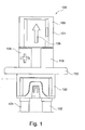
- FIG. 12 shows a foreign start point 100 having a first electrical connection part 101 and a second electrical connection part 102 for connecting a starting aid tool, respectively.
- the two connection parts 101, 102 are designed like a tube and are passed through the base element 120, 122, 110.
- the base element is, for example, a plurality of plastic parts, which are produced by injection molding or die casting.
- the basic element may for example be in two parts (two half-shells). Here, if necessary, the connection parts are inserted and the half shells clipped together.
- an insulating cover 105 which has a left lower sleeve-like region 106 and a right upper sleeve-like region 121 into which the two corresponding upper regions of the connecting parts 101, 102 are inserted.
- an upwardly directed arrow 109 may be located on the top of the insulating cover, which indicates in which direction the insulating cover 105 must be moved to take the release position.
- the base member of the foreign launching point has a flange-like portion 122 adapted to abut against and attach to a surface of a metal bracket or other support member.
- the flange-like element 122 of the base member in this embodiment has three recesses (or more or less) 201, 202, 203, which are in the region of three vertices of the square cross-section element 122 and through which Fixing screws can be passed.
- a plus symbol 107 and a minus symbol 108 are provided to designate the locations of the plus pole and the minus pole of the jump start point.
- Fig. 3 shows a perspective view of the Fremdstart Vietnameses 100 in the installed state.
- the screwing through the holes 201, 202 and 203 can be seen.
- To the two connection parts 101, 102 are connected further lines 301, 302, which each have a sheath 303, 304.
- the sheath 303 and 304 is a corrugated hose which is attached over the cables for protection.
- the two connection parts 101, 102 are plugged into the corresponding counterparts 301, 302 or otherwise connected thereto.
- the connecting parts 101, 102 and the related continuations 301, 302 may be made in one piece.
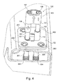
- Fig. 4 shows a jump start point with the insulating cover 105 pulled up.
- the two connection areas 401, 402 are exposed, to which the corresponding jump aid tools (for example pole terminals) can be connected.
- the two connection areas 401, 402 are on different levels, so are arranged offset in height to each other. In this way, it can be ensured that the two jump-start tools can be attached to each other uninfluenced.
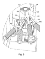
- Fig. 5 shows a jump start point 100 with pushed up insulating cover 105 and two connected jumpers tools 501, 502 in the form of collets.
- the insulating cover closes automatically, ie moves downwards. This can be achieved by spring elements integrated in the jump start point (see also Fig. 8 ).
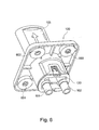
- Fig. 6 shows a perspective view of the Fremdstartddlings 100.
- the bushings 201, 202, 203 see Fig. 2 .
- metallic sleeve members 601, 602, 603 are fitted, through which the fastening screws or fastening bolts are guided.
- Fig. 7 shows the foreign launch point 100 with continuations 301, 302 connected thereto and corresponding casings 303, 304.
- the casings 303, 304 can be embodied in the form of spring elements, whereby a flexibility of the continuations 301, 302 is achieved.
- At the end of the continuations 301, 302 are pole pieces 701, 702, to which further wiring can be screwed.
- Fig. 8 shows a sectional view through a Fremdstartddling 100, which is screwed onto a support 820 (see also Fig. 4 ).
- connection parts 101, 102 is designed like a tube and passed through the base element 120, 122, 801, 802, 803, 804.
- the base element is in the embodiment of Fig. 8 designed in two parts and has a flange-like outer element 122, 120, 802, 803, 804 and an inner member 801.
- the outer member has a lower portion 120, in which the inner member 801 is inserted, and a collar-shaped flange-like, upper portion 803, 804, the underside of which is designed for planar contact with the surface of the support member 820.
- connection parts 101, 102 are attached.
- the two tubular connecting parts have circumferential grooves 805, 806 or 807, 808 into which corresponding lugs of the base element engage.
- the combination of base element and connecting parts is produced by encapsulation of the connecting parts, but it can also be two Plastic half shells are, in which the connecting parts inserted and the half-shells are clipped.
- the flange 120, 122 can then be slid over it.
- connection parts 101, 102 moreover have constrictions of their inner diameter in the upper region. These constrictions are generated, for example, by bending a pipe section in each case in this area inward, so that inner stops 813, 814 are formed. Furthermore, each insert elements 815, 816 are provided, which are inserted from above into the tube interior of the connecting parts 101, 102 and then secured against axial slippage on the one hand by the tube constrictions 813, 814 and on the other hand by upper stops 830, 831.
- inserts 815, 816 are longitudinally extending, thickening in its lower and upper region pin-shaped elements 840, 841 inserted, which are used to operate the two spring elements 809, 810.
- These two elements 840, 841 have at their lower ends thickenings 811, 812, which prevent the spring elements 809, 810 slide past it.
- the spring members 809, 810 serve to provide a restoring force to automatically retract the insulating cover from the release position to the rest position when the jump start tools are removed.
- Fig. 9 shows an exploded view of a Fremdstartddlings according to an embodiment of the invention. How out Fig. 9 it can be seen, all the components can be mounted by sticking together.
- Fig. 10 shows the two main assemblies of a Fremdstartddlings according to an embodiment of the invention.
- the inner part 120 of the base member has on two opposite outer sides in each case a nose 1003, in each of which a corresponding hook 1001, which are attached to the separate, lower part 1002 of the base member, engage when the two parts 120, 1002 during assembly of the Fremdstartpossessess be pushed into each other.
- Fig. 11 shows a motor vehicle 900 having a jump start point 100 according to an embodiment of the invention.
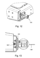
- the jump start point 100 is bolted to the rear frame of a truck or other vehicle (see FIG Fig. 12 ).
- Fig. 13 shows a side view of the bolted starter point of Fig. 12 .
- the entire front contacting area (see encircling) can be pushed back over the attached snap-in jaws by the adapter plate so as to avoid a short circuit on the body of the vehicle.
- the flexible snap jaws 1001 (see Fig. 10 ) and the front area of the jump start point can be pushed into the vehicle.
Landscapes
- Details Of Connecting Devices For Male And Female Coupling (AREA)
- Motor Or Generator Frames (AREA)
Description
- Die Erfindung betrifft einen Fremdstartpunkt mit zwei Anschlussteilen.
- Bei Kraftfahrzeugen wird die Starterbatterie oftmals in einem durch Unfälle nicht gefährdeten Bereich angeordnet, um z. B. nach einem Frontalunfall die Bordnetzversorgung für ein Sicherheitssystem und die Beleuchtung aufrecht zu erhalten. So wird die Starterbatterie beispielsweise im Kofferraum oder unter Abdeckungen angeordnet. Aufgrund dieser Positionierung der Starterbatterie ist jedoch ein Fremdstart oder eine Fremdladung ohne spezielle Vorrichtungen oft nicht mehr möglich, weil herkömmliche Startzangen (Polzangen) keinen Zugang zu einer derart gelagerten Starterbatterie haben. Aus diesem Grund ist oft ein spezieller Fremdstartpunkt im verhältnismäßig leicht zugänglichen Motorraum von Kraftfahrzeugen vorgesehen, an welche eine Polzange angeschlossen werden kann. Der Fremdstartpunkt kann sich an jeder Position an der Karosserie befinden und die Einbauposition muss nicht auf den Motorraum beschränkt sein.
-
DE 10 2006 041 949 B3 beschreibt einen Fremdstartpunkt mit einem Anschlussteil, das zumindest teilweise aus einer Isolierung herausziehbar ist. -
WO 2007/019924 A1 beschreibt einen Fremdstartstützpunkt mit einem elektrischen Anschlussteil zum Anschluss eines Starthilfe-Werkzeugs und mit einer das Anschlussteil in einer Ruheposition umgebenden Isolierabdeckung. Die Isolierabdeckung weist eine Isolierhülse auf, welche das Anschlussteil umgibt und gegen eine Federkraft zwischen der Ruheposition und einer das Anschlussteil zur elektrischen Kontaktierung freigebenden Freigabeposition beweglich ist. - Es ist eine Aufgabe der Erfindung, einen Fremdstartpunkt zum Anschluss von Polzangen anzugeben, der eine einfache und sichere Handhabung gewährleistet.
- Es sind ein Fremdstartpunkt und ein Fahrzeug mit einem solchen Fremdstartpunktgemäß den Merkmalen der unabhängigen Patentansprüche angegeben. Weiterbildungen der Erfindung ergeben sich aus den Unteransprüchen.
- Gemäß der Erfindung weist der Fremdstartpunkt ein erstes elektrisches Anschlussteil, ein zweites elektrisches Anschlussteil und eine Isolierabdeckung auf. Die beiden elektrischen Anschlussteile sind ausgeführt, um darin jeweils ein Starthilfe-Werkzeug, wie beispielsweise eine Polzange, anzuschließen. Die Isolierabdeckung umgibt die zwei Anschlussteile (bzw. entsprechende Anschlussbereiche der beiden Anschlussteile) in einer Ruheposition, so dass hierdurch eine elektrische Isolation sowie ein mechanischer Schutz gegenüber der Umgebung gewährleistet ist. Die Isolierabdeckung ist von der Ruheposition in eine Freigabeposition verschiebbar, in welcher ein erster Anschlussbereich des ersten Anschlussteils und ein zweiter Anschlussbereich des zweiten Anschlussteils zur elektrischen Kontaktierung durch die beiden Starthilfe-Werkzeuge freigegeben sind. In der Ruheposition sind diese beiden Anschlussbereiche von der Isolierabdeckung umgeben.
- Schleifkontakte, wie sie im Stand der Technik verwendet werden, sind nicht erforderlich. Weiterhin weist der Fremdstartpunkt sowohl einen Pluspol (erstes elektrisches Anschlussteil) und einen Minuspol (zweites elektrisches Anschlussteil) auf. Diese beiden Pole können also in einem Bauteil integriert sein.
- Die beiden Anschlussteile können am Einbauort fixiert, also unbeweglich sein. Lediglich die Isolierabdeckung kann relativ zu den beiden Anschlussteilen bewegt werden, beispielsweise indem sie von einem Benutzer gezogen wird. Natürlich kann auch ein elektrischer Auslösemechanismus vorgesehen sein, der die Isolierabdeckung von der Ruheposition in die Freigabeposition bewegt, so dass kein manuelles Bewegen erforderlich ist.
- Gemäß einem Ausführungsbeispiel der Erfindung weist die Isolierabdeckung einen Anschlag auf, der ein Ablösen der Isolierabdeckung von den zwei Anschlussteilen verhindert. So kann die Isolierabdeckung von der Ruheposition in die Freigabeposition bewegt werden, allerdings nicht weiter. Auf diese Weise kann ein versehentliches Abziehen der Isolierabdeckung vermieden werden.
- Gemäß einem weiteren Ausführungsbeispiel der Erfindung weist der Fremdstartpunkt weiterhin eine erste Rückholfeder und ggf. auch noch eine zweite Rückholfeder auf. Die erste Rückholfeder ist hierbei in dem ersten elektrischen Anschlussteil untergebracht. Falls eine zweite Rückholfeder vorgesehen ist, ist diese in dem zweiten elektrischen Anschlussteil untergebracht. Die Isolierabdeckung wird gegen die Federkraft der ersten Rückholfeder und auch gegen die Federkraft der zweiten Rückholfeder (falls eine solche vorgesehen ist) von der Ruheposition in die Freigabeposition bewegt. Die Rückholfedern dienen der automatischen Rückbewegung der Isolierabdeckung von der Freigabeposition in die Ruheposition, wenn die Isolierabdeckung vom Benutzer freigegeben ist.
- Auf diese Weise wird gewährleistet, dass der Fremdstartpunkt automatisch isoliert wird, wenn er nicht verwendet wird, da die Isolierabdeckung die beiden Anschlussteile selbständig verschließt, wenn die Polklemmen abgezogen werden.
- Gemäß einem weiteren Ausführungsbeispiel der Erfindung weist die Isolierabdeckung einen ersten und einen zweiten hülsenartigen Bereich auf. Der erste hülsenartige Bereich deckt in der Ruheposition der Isolierabdeckung den ersten Anschlussbereich des ersten Anschlussteils ab und der zweite hülsenartige Bereich deckt in der Ruheposition den zweiten Anschlussbereich des zweiten Anschlussteils ab.
- Gemäß der Erfindung sind die beiden Anschlussbereiche der beiden Anschlussteile in der Freigabeposition versetzt zueinander angeordnet, so dass sich die beiden Starthilfe-Werkzeuge beim Anschluss an die beiden Anschlussteile nicht gegenseitig behindern können.
- Auf diese Weise wird die Benutzung des Fremdstartpunkts erleichtert.
- Gemäß einem weiteren Ausführungsbeispiel der Erfindung weist der Fremdstartpunkt weiterhin ein Basiselement auf, durch welches die beiden Anschlussteile hindurchgeführt sind. An der Oberseite des Basiselements stößt die Isolierabdeckung in der Ruheposition an, so dass die beiden Anschlussteile im Bereich der Oberseite des Basiselements isoliert sind.
- Durch eine geeignete Dimensionierung des Basiselements kann der Fremdstartpunkt eine hohe mechanische Stabilität aufweisen und leicht an einer entsprechenden Einbaustelle im Kraftfahrzeug fixiert werden.
- Beispielsweise ist das Basiselement aus zwei Spritzgussteilen hergestellt. Ebenso kann das Gehäuse der Isolierabdeckung ein Spritzgussteil sein.
- Gemäß einem weiteren Ausführungsbeispiel der Erfindung weist die Oberseite des Basiselements einen ersten Anstoßbereich auf, an dem das erste Anschlussteil aus dem Basiselement heraustritt und an welchem der erste hülsenartige Bereich der Isolierabdeckung anstößt, wenn sich die Isolierabdeckung in der Ruheposition befindet. Ebenso kann die Oberseite des Basiselements einen entsprechenden zweiten Anstoßbereich aufweisen, an dem das zweite Anschlussteil aus dem Basiselement heraustritt und an den der zweite hülsenartige Bereich der Isolierabdeckung anstößt, wenn sich die Isolierabdeckung in der Ruheposition befindet.
- Gemäß einem weiteren Ausführungsbeispiel der Erfindung liegen diese zwei Anstoßbereiche auf verschiedenen Ebenen. Dies führt dazu, dass auch die beiden Anschlussbereiche der Anschlussteile auf verschiedenen Ebenen liegen, so dass sich die Polklemmen beim Anschluss nicht gegenseitig behindern können.
- Gemäß einem weiteren Ausführungsbeispiel der Erfindung sind die zwei Anschlussteile rohrartig und gerade (linear) ausgeführt.
- Gemäß einem weiteren Ausführungsbeispiel der Erfindung weisen die zwei Anschlussteile an ihren Enden, die sich hinter den Anschlussbereichen, also an der vom Benutzer zugänglichen Seite des Fremdstartpunkts befinden, jeweils eine Verengung des Innendurchmessers auf, welche zumindest indirekt als Abstützung für die Rückholfedern dienen.
- Gemäß einem weiteren Aspekt der Erfindung ist ein Fahrzeug mit einem oben und im Folgenden beschriebenen Fremdstartpunkt angegeben.
- Im Folgenden werden mit Verweis auf die Figuren Ausführungsbeispiele der Erfindung beschrieben.
-
-
Fig. 1 zeigt einen Fremdstartpunkt gemäß einem Ausführungsbeispiel der Erfindung. -
Fig. 2 zeigt den Fremdstartpunkt derFig. 1 in Draufsicht. -
Fig. 3 zeigt eine weitere Darstellung des Fremdstartpunkts derFig. 1 . -
Fig. 4 zeigt den Fremdstartpunkt derFig. 1 mit der Isolierabdeckung in Freigabeposition. -
Fig. 5 zeigt den Fremdstartpunkt derFig. 1 mit angelegten Polklemmen. -
Fig. 6 zeigt eine weitere Darstellung des Fremdstartpunkts gemäß einem Ausführungsbeispiel der Erfindung. -
Fig. 7 zeigt einen Fremdstartpunkt mit daran angeschlossenen Leitungen gemäß einem Ausführungsbeispiel der Erfindung. -
Fig. 8 zeigt eine Schnittdarstellung durch einen Fremdstartpunkt gemäß einem Ausführungsbeispiel der Erfindung. -
Fig. 9 zeigt eine Explosionsdarstellung eines Fremdstartpunkts gemäß einem Ausführungsbeispiel der Erfindung. -
Fig. 10 zeigt die beiden Hauptbaugruppen eines Fremdstartpunkts gemäß einem Ausführungsbeispiel der Erfindung. -
Fig. 11 zeigt ein Fahrzeug mit einem Fremdstartpunkt gemäß einem Ausführungsbeispiel der Erfindung. -
Fig. 12 zeigt einen Fremdstartpunkt in angeschraubten Zustand. -
Fig. 13 zeigt eine seitliche Ansicht auf den angeschraubten Fremdstartpunkt derFig. 12 . - Die Darstellungen in den Figuren sind schematisch und nicht maßstäblich. In der folgenden Figurenbeschreibung werden für die gleichen oder ähnlichen Elemente die gleichen Bezugsziffern verwendet.
-
Fig. 1 zeigt einen Fremdstartpunkt 100, der ein erstes elektrisches Anschlussteil 101 und ein zweites elektrisches Anschlussteil 102 zum Anschließen jeweils eines Starthilfe-Werkzeugs aufweist. Die beiden Anschlussteile 101, 102 sind rohrartig ausgeführt und sind durch das Basiselement 120, 122, 110 hindurchgeführt. Bei dem Basiselement handelt es sich beispielsweise um mehrere Kunststoffteile, die im Spritzgussverfahren oder Druckgussverfahren hergestellt sind. Das Basiselement kann beispielsweise zweiteilig sein (zwei Halbschalen). Hier werden ggf. die Anschlussteile eingelegt und die Halbschalen zusammengeklipst. - Weiterhin ist eine Isolierabdeckung 105 vorgesehen, die einen linken unteren hülsenartigen Bereich 106 und einen rechten oberen hülsenartigen Bereich 121 aufweist, in welche die beiden entsprechenden oberen Bereiche der Anschlussteile 101, 102 eingeschoben sind.
- Weiterhin kann sich ein nach oben gerichteter Pfeil 109 auf der Oberseite der Isolierabdeckung befinden, welcher angibt, in welche Richtung die Isolierabdeckung 105 zum Einnehmen der Freigabeposition bewegt werden muss.
- Das Basiselement des Fremdstartpunkts weist einen flanschartigen Bereich 122 auf, der zur Anlage an einer Oberfläche eines Metallbügels oder eines anderen Trägerelements und zur Befestigung daran ausgeführt ist.
-
Fig. 2 zeigt eine Draufsicht auf den Fremdstartpunkt 100. Das flanschartige Element 122 des Basiselements weist in diesem Ausführungsbeispiel drei Ausnehmungen (oder mehr oder weniger) 201, 202, 203 auf, die sich im Bereich von drei Eckpunkten des im Querschnitt viereckigen Elements 122 befinden und durch welche Befestigungsschrauben hindurchgeführt werden können. Wie inFig. 2 zu erkennen, weist die Oberseite der Isolierabdeckung 105 einen Handgriff 204 auf, an welchem die Abdeckung herausgezogen werden kann. Weiterhin sind ein Plus-Symbol 107 sowie ein Minus-Symbol 108 vorgesehen, um die Orte des Pluspols und des Minuspols des Fremdstartpunkts zu bezeichnen. -
Fig. 3 zeigt eine perspektivische Darstellung des Fremdstartpunkts 100 im eingebauten Zustand. Insbesondere sind die Verschraubungen durch die Löcher 201, 202 und 203 zu erkennen. An die beiden Anschlussteile 101, 102 sind weiterführende Leitungen 301, 302 angeschlossen, welche jeweils eine Ummantelung 303, 304 aufweisen. Bei der Ummantelung 303 und 304 handelt es sich um einen Wellschlauch der zum Schutz über die Kabel angebracht wird. Beispielsweise sind die beiden Anschlussteile 101, 102 in die entsprechenden Gegenstücke 301, 302 eingesteckt oder anderweitig damit verbunden. Auch können die Anschlussteile 101, 102 und die damit zusammenhängenden Weiterführungen 301, 302 einstückig ausgeführt sein. -
Fig. 4 zeigt einen Fremdstartpunkt mit hochgezogener Isolierabdeckung 105. Hierdurch werden die beiden Anschlussbereiche 401, 402 freigelegt, an welchen die entsprechenden Starthilfe-Werkzeuge (beispielsweise Polklemmen) angeschlossen werden können. Wie in derFig. 4 zu sehen, befinden sich die beiden Anschlussbereiche 401, 402 auf verschiedenen Ebenen, sind also höhenversetzt zueinander angeordnet. Auf diese Weise kann gewährleistet werden, dass die beiden Starthilfe-Werkzeuge voneinander unbeeinflusst angebracht werden können. -
Fig. 5 zeigt einen Fremdstartpunkt 100 mit hochgeschobener Isolierabdeckung 105 sowie zwei angeschlossenen Starthilfe-Werkzeugen 501, 502 in Form von Polzangen. - Werden die beiden Polzangen wieder abgenommen, schließt die Isolierabdeckung automatisch, bewegt sich also nach unten. Dies kann durch im Fremdstartpunkt integrierte Federelemente erreicht werden (siehe auch
Fig. 8 ). -
Fig. 6 zeigt eine perspektivische Darstellung des Fremdstartpunkts 100. In den Durchführungen 201, 202, 203 (sieheFig. 2 ) sind metallische Hülsenelemente 601, 602, 603 eingepasst, durch welche die Befestigungsschrauben bzw. Befestigungsbolzen geführt werden. -
Fig. 7 zeigt den Fremdstartpunkt 100 mit daran angeschlossenen Weiterführungen 301, 302 und entsprechenden Ummantelungen 303, 304. Die Ummantelungen 303, 304 können in Form von Federelementen ausgeführt sein, wodurch eine Flexibilität der Weiterführungen 301, 302 erreicht wird. Am Ende der Weiterführungen 301, 302 befinden sich Polschuhe 701, 702, an welche weiterführende Verkabelungen angeschraubt werden können. -
Fig. 8 zeigt eine Schnittdarstellung durch einen Fremdstartpunkt 100, der auf einem Träger 820 aufgeschraubt ist (siehe auchFig. 4 ). - Jedes der beiden Anschlussteile 101, 102 ist rohrartig ausgeführt und durch das Basiselement 120, 122, 801, 802, 803, 804 hindurchgeführt. Das Basiselement ist beim Ausführungsbeispiel der
Fig. 8 zweiteilig ausgeführt und weist ein flanschartiges äußeres Element 122, 120, 802, 803, 804 sowie ein inneres Element 801 auf. - Diese beiden Elemente sind ineinander geschoben und das innere Element 801 weist an der Unterseite einen Anschlag 821 auf, der gegen das flanschartige äußere Element stößt, so dass das innere Element nicht weiter nach oben gezogen werden kann. Das äußere Element weist einen unteren Bereich 120 auf, in dem das innere Element 801 eingeschoben ist, sowie einen kragenförmigen flanschartigen, oberen Bereich 803, 804, dessen Unterseite zur planaren Anlage an die Oberfläche des Trägerelements 820 ausgeführt ist.
- In dem Basiselement sind die beiden Anschlussteile 101, 102 befestigt. Hierfür weisen die beiden rohrförmigen Anschlussteile umfangseitige Nuten 805, 806 bzw. 807, 808 auf, in welche entsprechende Nasen des Basiselements eingreifen. Beispielsweise wird die Kombination aus Basiselement und Anschlussteilen durch Umspritzen der Anschlussteile hergestellt, es können aber auch zwei Kunststoffhalbschalen sein, in welche die Anschlussteile eingelegt und die Halbschalen verklipst werden.
- Nach der Herstellung dieser Kombination kann dann der Flansch 120, 122 darüber geschoben werden.
- Die beiden Anschlussteile 101, 102 weisen darüber hinaus Verengungen ihres Innendurchmessers im oberen Bereich auf. Diese Verengungen werden beispielsweise dadurch erzeugt, dass in diesem Bereich jeweils ein Rohrabschnitt nach innen gebogen wird, so dass sich innere Anschläge 813, 814 ausbilden. Weiterhin sind jeweils Einlegeelemente 815, 816 vorgesehen, die von oben in das Rohrinnere der Anschlussteile 101, 102 eingeschoben werden und dann gegen axiales Verrutschen einerseits durch die Rohrverengungen 813, 814 und andererseits durch obere Anschläge 830, 831 gesichert sind.
- Durch diese Einlegeteile 815, 816 sind sich longitudinal erstreckende, in ihrem unteren und oberen Bereich verdickende stiftförmige Elemente 840, 841 eingeschoben, welche zur Bedienung der beiden Federelemente 809, 810 eingesetzt werden. Diese beiden Elemente 840, 841 weisen an ihren unteren Enden Verdickungen 811, 812 auf, welche verhindern, dass die Federelemente 809, 810 daran vorbeigleiten. Die Federelemente 809, 810 dienen der Bereitstellung einer Rückstellkraft, um die Isolierabdeckung automatisch von der Freigabeposition in die Ruheposition zurückzuziehen, wenn die Starthilfe-Werkzeuge entfernt sind.
-
Fig. 9 zeigt eine Explosionsdarstellung eines Fremdstartpunkts gemäß einem Ausführungsbeispiel der Erfindung. Wie ausFig. 9 ersichtlich ist, können sämtliche Bestandteile durch aneinanderstecken montiert werden. -
Fig. 10 zeigt die beiden Hauptbaugruppen eines Fremdstartpunkts gemäß einem Ausführungsbeispiel der Erfindung. Das innere Teil 120 des Basiselements weist an zwei gegenüberliegenden Außenseiten jeweils eine Nase 1003 auf, in welche jeweils ein entsprechender Haken 1001, die am separaten, unteren Teil 1002 des Basiselements angebracht sind, eingreifen, wenn die beiden Teile 120, 1002 bei der Montage des Fremdstartpunktes ineinander geschoben werden. -
Fig. 11 zeigt ein Kraftfahrzeug 900 mit einem Fremdstartpunkt 100 gemäß einem Ausführungsbeispiel der Erfindung. Der Fremdstartpunkt 100 ist beispielsweise am hinteren Rahmen eines Lastkraftwagens oder anderen Fahrzeugs angeschraubt (sieheFig. 12 ). -
Fig. 13 zeigt eine seitliche Ansicht auf den angeschraubten Fremdstartpunkt derFig. 12 . Im Crashfall, bei dem in Crashrichtung 1301 eine Kraft auf den Fremdstartpunkt einwirkt, kann der gesamte vordere Kontaktierungsbereich (siehe Einkreisung) über die angebrachten Schnappbacken durch die Adapterplatte nach hinten geschoben werden, um so einen Kurzschluss auf der Karosserie des Fahrzeugs zu vermeiden. In diesem Fall geben die flexiblen Schnappbacken 1001 (sieheFig. 10 ) nach und der vordere Bereich des Fremdstartpunkts kann in das Fahrzeug hinein geschoben werden. - Ergänzend sei darauf hingewiesen, dass "umfassend" und "aufweisend" keine anderen Elemente oder Schritte ausschließt und "eine" oder "ein" keine Vielzahl ausschließt. Ferner sei darauf hingewiesen, dass Merkmale oder Schritte, die mit Verweis auf eines der obigen Ausführungsbeispiele beschrieben worden sind, auch in Kombination mit anderen Merkmalen oder Schritten anderer oben beschriebener Ausführungsbeispiele verwendet werden können. Bezugszeichen in den Ansprüchen sind nicht als Einschränkungen anzusehen.
Claims (10)
- Fremdstartpunkt, aufweisend:ein erstes elektrisches Anschlussteil (101) und ein zweites elektrisches Anschlussteil (102) zum Anschließen jeweils eines Starthilfe-Werkzeugs (501, 502);eine die zwei Anschlussteile (101, 102) in einer Ruheposition umgebende Isolierabdeckung (105);wobei die Isolierabdeckung (105) von der Ruheposition in eine Freigabeposition bewegbar ist, in welcher ein erster Anschlussbereich (401) des ersten Anschlussteils (101) und ein zweiter Anschlussbereich (402) des zweiten Anschlussteils (102) zur elektrischen Kontaktierung durch die beiden Starthilfe-Werkzeuge (501, 502) freigegeben sind;wobei der erste Anschlussbereich (401) des ersten Anschlussteils (101) und der zweite Anschlussbereich (402) des zweiten Anschlussteils (102) in der Freigabeposition höhenversetzt zueinander angeordnet sind, so dass sich die beiden Starthilfe-Werkzeuge (501, 502) beim Anschluss an die beiden Anschlussteile (101, 102) nicht behindern.
- Fremdstartpunkt nach Anspruch 1,
wobei die Isolierabdeckung einen Anschlag (811, 812) aufweist, der ein Abstecken der Isolierabdeckung (105) von den zwei Anschlussteilen (101, 102) verhindert. - Fremdstartpunkt nach einem der vorhergehenden Ansprüche, weiterhin aufweisend:eine erste Rückholfeder (809) in dem ersten elektrischen Anschlussteil (101) und eine zweite Rückholfeder (810) in dem zweiten elektrischen Anschlussteil (102), gegen deren Federkräfte die Isolierabdeckung (105) von der Ruheposition in die Freigabeposition bewegbar ist;wobei die beiden Rückholfedern (809, 810) zur automatischen Rückbewegung der Isolierabdeckung (105) von der Freigabeposition in die Ruheposition ausgeführt sind, wenn die Isolierabdeckung freigegeben ist.
- Fremdstartpunkt nach einem der vorhergehenden Ansprüche,
wobei die Isolierabdeckung (105) einen ersten hülsenartigen Bereich (106) aufweist, der in der Ruheposition den ersten Anschlussbereich (401) des ersten Anschlussteils (101) abdeckt;
wobei die Isolierabdeckung (105) einen zweiten hülsenartigen Bereich (121) aufweist, der in der Ruheposition den zweiten Anschlussbereich (402) des zweiten Anschlussteils (102) abdeckt. - Fremdstartpunkt nach einem der vorhergehenden Ansprüche, weiterhin aufweisend:ein Basiselement (120, 122), durch welches die beiden Anschlussteile (101, 102) hindurchgeführt sind, und an dessen Oberseite die Isolierabdeckung (105) in der Ruheposition anstößt, so dass die beiden Anschlussteile (101, 102) im Bereich der Oberseite des Basiselements (120, 122) isoliert sind.
- Fremdstartpunkt nach Anspruch 5,
wobei die Oberseite des Basiselements (120, 122) einen ersten Anstoßbereich (820) aufweist, an dem das erste Anschlussteil (101) aus dem Basiselement (102, 122) heraustritt und an den der erste hülsenartige Bereich (106) der Isolierabdeckung (105) anstößt, wenn sich die Isolierabdeckung (105) in der Ruheposition befindet; und
wobei die Oberseite des Basiselements (120, 122) einen zweiten Anstoßbereich (821) aufweist, an dem das zweite Anschlussteil (102) aus dem Basiselement (102, 122) heraustritt und an den der zweite hülsenartige Bereich (121) der Isolierabdeckung (105) anstößt, wenn sich die Isolierabdeckung (105) in der Ruheposition befindet. - Fremdstartpunkt nach Anspruch 6,
wobei sich die zwei Anstoßbereiche (822, 823) auf verschiedenen Ebenen befinden. - Fremdstartpunkt nach einem der vorhergehenden Ansprüche,
wobei die zwei Anschlussteile (101, 102) rohrartig und gerade ausgeführt sind. - Fremdstartpunkt nach einem der vorhergehenden Ansprüche,
wobei die zwei Anschlussteile (101, 102) an ihren Enden, die sich hinter den Anschlussbereichen (401, 402) befinden, jeweils eine Verengung des Innendurchmessers aufweisen, welche zumindest indirekt als Abstützung für die Rückholfedern (809, 810) dienen. - Fahrzeug mit einem Fremdstartpunkt nach einem der Ansprüche 1 bis 9.
Priority Applications (1)
| Application Number | Priority Date | Filing Date | Title |
|---|---|---|---|
| EP20100168574 EP2405536B1 (de) | 2010-07-06 | 2010-07-06 | Fremdstartpunkt |
Applications Claiming Priority (1)
| Application Number | Priority Date | Filing Date | Title |
|---|---|---|---|
| EP20100168574 EP2405536B1 (de) | 2010-07-06 | 2010-07-06 | Fremdstartpunkt |
Publications (2)
| Publication Number | Publication Date |
|---|---|
| EP2405536A1 EP2405536A1 (de) | 2012-01-11 |
| EP2405536B1 true EP2405536B1 (de) | 2013-01-02 |
Family
ID=42830074
Family Applications (1)
| Application Number | Title | Priority Date | Filing Date |
|---|---|---|---|
| EP20100168574 Active EP2405536B1 (de) | 2010-07-06 | 2010-07-06 | Fremdstartpunkt |
Country Status (1)
| Country | Link |
|---|---|
| EP (1) | EP2405536B1 (de) |
Families Citing this family (2)
| Publication number | Priority date | Publication date | Assignee | Title |
|---|---|---|---|---|
| DE102013008319A1 (de) * | 2013-05-15 | 2014-11-20 | Wacker Neuson Produktion GmbH & Co. KG | Ausziehbare elektrische Anschlussvorichtung für ein Arbeitsgerät |
| EP3787126A1 (de) * | 2019-08-29 | 2021-03-03 | Swepac AB | Verbindungsvorrichtung |
Family Cites Families (3)
| Publication number | Priority date | Publication date | Assignee | Title |
|---|---|---|---|---|
| DE10118051B4 (de) * | 2001-04-11 | 2005-09-29 | Daimlerchrysler Ag | Batterienmessklemme mit Fremdstartstützpunkt |
| DE102005038578B3 (de) | 2005-08-16 | 2006-07-27 | Daimlerchrysler Ag | Fremdstartstützpunkt |
| DE102006041949B3 (de) | 2006-08-29 | 2007-08-02 | Apparatebau Kirchheim-Teck Gmbh | Fremdstartpunkt |
-
2010
- 2010-07-06 EP EP20100168574 patent/EP2405536B1/de active Active
Also Published As
| Publication number | Publication date |
|---|---|
| EP2405536A1 (de) | 2012-01-11 |
Similar Documents
| Publication | Publication Date | Title |
|---|---|---|
| EP3639335B1 (de) | Ladestation | |
| EP2612403A2 (de) | Elektrische komponente | |
| EP3804041A1 (de) | Modulares steckverbindersystem | |
| DE202005002921U1 (de) | Verbindungssystem, insbesondere elektrisches Verbindungssystem | |
| DE102012005043A1 (de) | Elektrische Wanddurchführung für Solaranlagen | |
| DE102019205050A1 (de) | Buchsenvorrichtung zum berührsicheren elektrischen Kontaktieren einer korrespondierenden Steckervorrichtung, Steckervorrichtung und Batteriemodul für eine Hochvoltbatterie | |
| EP3028349B1 (de) | Endlagenfixierung einer steckverbindung zur erhöhung der vibrationsfestigkeit | |
| DE102007005737A1 (de) | Kopfstützensystem für einen Fahrzeugsitz | |
| WO2012072737A1 (de) | Ladekabelseitiges steckerteil einer elektrischen steckvorrichtung eines fahrzeugs | |
| EP2405536A1 (de) | Fremdstartpunkt | |
| DE102013005092A1 (de) | Verbindersystem zum mechanischen Verbinden und elektrischen Kontaktieren von zwei elektrisch leitfähigen Komponenten | |
| EP0444478A1 (de) | Kontaktträger für eine Steckdose oder einen Stecker für eine Steckverbindungen fÀ¼r den elektrischen Anschluss von Kraftfahrzeuganhängern | |
| DE102010050567A1 (de) | Gehäuse für einen Steckverbinder | |
| EP2658040B1 (de) | Stecker | |
| DE102004054310B4 (de) | Elektrische Verbindung eines Kontaktstiftes mit einem Blechbauteil | |
| DE102023128664B3 (de) | Ladesteckerhalter für eine Ladevorrichtung zum Laden von Elektrofahrzeugen, und Ladevorrichtung | |
| WO2006133824A1 (de) | Fremdstartstützpunkt | |
| EP3123566B1 (de) | Kontaktbuchse für eine steckdose oder kupplung | |
| DE102005038578B3 (de) | Fremdstartstützpunkt | |
| DE102012004340A1 (de) | Messspitze | |
| DE102006041949B3 (de) | Fremdstartpunkt | |
| DE202011001995U1 (de) | Fremdstartpunktvorrichtung | |
| DE102015113086B4 (de) | Steckverbindungsvorrichtung mit Leitungssteckverbinder und Windschutzhülle | |
| DE202009014961U1 (de) | Elektrischer Rechteckwinkelsteckverbinder | |
| DE102011103866A1 (de) | Stromkabel und elektrische Ladevorrichtung für ein Fahrzeug |
Legal Events
| Date | Code | Title | Description |
|---|---|---|---|
| AK | Designated contracting states |
Kind code of ref document: A1 Designated state(s): AL AT BE BG CH CY CZ DE DK EE ES FI FR GB GR HR HU IE IS IT LI LT LU LV MC MK MT NL NO PL PT RO SE SI SK SM TR |
|
| AX | Request for extension of the european patent |
Extension state: BA ME RS |
|
| PUAI | Public reference made under article 153(3) epc to a published international application that has entered the european phase |
Free format text: ORIGINAL CODE: 0009012 |
|
| 17P | Request for examination filed |
Effective date: 20120711 |
|
| GRAP | Despatch of communication of intention to grant a patent |
Free format text: ORIGINAL CODE: EPIDOSNIGR1 |
|
| GRAS | Grant fee paid |
Free format text: ORIGINAL CODE: EPIDOSNIGR3 |
|
| GRAA | (expected) grant |
Free format text: ORIGINAL CODE: 0009210 |
|
| AK | Designated contracting states |
Kind code of ref document: B1 Designated state(s): AL AT BE BG CH CY CZ DE DK EE ES FI FR GB GR HR HU IE IS IT LI LT LU LV MC MK MT NL NO PL PT RO SE SI SK SM TR |
|
| REG | Reference to a national code |
Ref country code: GB Ref legal event code: FG4D Free format text: NOT ENGLISH |
|
| REG | Reference to a national code |
Ref country code: AT Ref legal event code: REF Ref document number: 592053 Country of ref document: AT Kind code of ref document: T Effective date: 20130115 Ref country code: CH Ref legal event code: EP |
|
| REG | Reference to a national code |
Ref country code: IE Ref legal event code: FG4D Free format text: LANGUAGE OF EP DOCUMENT: GERMAN |
|
| REG | Reference to a national code |
Ref country code: DE Ref legal event code: R096 Ref document number: 502010002007 Country of ref document: DE Effective date: 20130228 |
|
| REG | Reference to a national code |
Ref country code: SE Ref legal event code: TRGR |
|
| REG | Reference to a national code |
Ref country code: NL Ref legal event code: T3 |
|
| PG25 | Lapsed in a contracting state [announced via postgrant information from national office to epo] |
Ref country code: SI Free format text: LAPSE BECAUSE OF FAILURE TO SUBMIT A TRANSLATION OF THE DESCRIPTION OR TO PAY THE FEE WITHIN THE PRESCRIBED TIME-LIMIT Effective date: 20130102 |
|
| REG | Reference to a national code |
Ref country code: LT Ref legal event code: MG4D |
|
| PG25 | Lapsed in a contracting state [announced via postgrant information from national office to epo] |
Ref country code: ES Free format text: LAPSE BECAUSE OF FAILURE TO SUBMIT A TRANSLATION OF THE DESCRIPTION OR TO PAY THE FEE WITHIN THE PRESCRIBED TIME-LIMIT Effective date: 20130413 Ref country code: NO Free format text: LAPSE BECAUSE OF FAILURE TO SUBMIT A TRANSLATION OF THE DESCRIPTION OR TO PAY THE FEE WITHIN THE PRESCRIBED TIME-LIMIT Effective date: 20130402 Ref country code: BG Free format text: LAPSE BECAUSE OF FAILURE TO SUBMIT A TRANSLATION OF THE DESCRIPTION OR TO PAY THE FEE WITHIN THE PRESCRIBED TIME-LIMIT Effective date: 20130402 Ref country code: LT Free format text: LAPSE BECAUSE OF FAILURE TO SUBMIT A TRANSLATION OF THE DESCRIPTION OR TO PAY THE FEE WITHIN THE PRESCRIBED TIME-LIMIT Effective date: 20130102 Ref country code: IS Free format text: LAPSE BECAUSE OF FAILURE TO SUBMIT A TRANSLATION OF THE DESCRIPTION OR TO PAY THE FEE WITHIN THE PRESCRIBED TIME-LIMIT Effective date: 20130502 Ref country code: CZ Free format text: LAPSE BECAUSE OF FAILURE TO SUBMIT A TRANSLATION OF THE DESCRIPTION OR TO PAY THE FEE WITHIN THE PRESCRIBED TIME-LIMIT Effective date: 20130102 |
|
| PG25 | Lapsed in a contracting state [announced via postgrant information from national office to epo] |
Ref country code: PT Free format text: LAPSE BECAUSE OF FAILURE TO SUBMIT A TRANSLATION OF THE DESCRIPTION OR TO PAY THE FEE WITHIN THE PRESCRIBED TIME-LIMIT Effective date: 20130502 Ref country code: FI Free format text: LAPSE BECAUSE OF FAILURE TO SUBMIT A TRANSLATION OF THE DESCRIPTION OR TO PAY THE FEE WITHIN THE PRESCRIBED TIME-LIMIT Effective date: 20130102 Ref country code: PL Free format text: LAPSE BECAUSE OF FAILURE TO SUBMIT A TRANSLATION OF THE DESCRIPTION OR TO PAY THE FEE WITHIN THE PRESCRIBED TIME-LIMIT Effective date: 20130102 Ref country code: LV Free format text: LAPSE BECAUSE OF FAILURE TO SUBMIT A TRANSLATION OF THE DESCRIPTION OR TO PAY THE FEE WITHIN THE PRESCRIBED TIME-LIMIT Effective date: 20130102 Ref country code: GR Free format text: LAPSE BECAUSE OF FAILURE TO SUBMIT A TRANSLATION OF THE DESCRIPTION OR TO PAY THE FEE WITHIN THE PRESCRIBED TIME-LIMIT Effective date: 20130403 |
|
| PG25 | Lapsed in a contracting state [announced via postgrant information from national office to epo] |
Ref country code: HR Free format text: LAPSE BECAUSE OF FAILURE TO SUBMIT A TRANSLATION OF THE DESCRIPTION OR TO PAY THE FEE WITHIN THE PRESCRIBED TIME-LIMIT Effective date: 20130102 |
|
| PG25 | Lapsed in a contracting state [announced via postgrant information from national office to epo] |
Ref country code: SK Free format text: LAPSE BECAUSE OF FAILURE TO SUBMIT A TRANSLATION OF THE DESCRIPTION OR TO PAY THE FEE WITHIN THE PRESCRIBED TIME-LIMIT Effective date: 20130102 Ref country code: RO Free format text: LAPSE BECAUSE OF FAILURE TO SUBMIT A TRANSLATION OF THE DESCRIPTION OR TO PAY THE FEE WITHIN THE PRESCRIBED TIME-LIMIT Effective date: 20130102 Ref country code: EE Free format text: LAPSE BECAUSE OF FAILURE TO SUBMIT A TRANSLATION OF THE DESCRIPTION OR TO PAY THE FEE WITHIN THE PRESCRIBED TIME-LIMIT Effective date: 20130102 Ref country code: DK Free format text: LAPSE BECAUSE OF FAILURE TO SUBMIT A TRANSLATION OF THE DESCRIPTION OR TO PAY THE FEE WITHIN THE PRESCRIBED TIME-LIMIT Effective date: 20130102 |
|
| PLBE | No opposition filed within time limit |
Free format text: ORIGINAL CODE: 0009261 |
|
| STAA | Information on the status of an ep patent application or granted ep patent |
Free format text: STATUS: NO OPPOSITION FILED WITHIN TIME LIMIT |
|
| PG25 | Lapsed in a contracting state [announced via postgrant information from national office to epo] |
Ref country code: CY Free format text: LAPSE BECAUSE OF FAILURE TO SUBMIT A TRANSLATION OF THE DESCRIPTION OR TO PAY THE FEE WITHIN THE PRESCRIBED TIME-LIMIT Effective date: 20130102 |
|
| 26N | No opposition filed |
Effective date: 20131003 |
|
| REG | Reference to a national code |
Ref country code: DE Ref legal event code: R097 Ref document number: 502010002007 Country of ref document: DE Effective date: 20131003 |
|
| BERE | Be: lapsed |
Owner name: INTERCABLE G.M.B.H. Effective date: 20130731 |
|
| PG25 | Lapsed in a contracting state [announced via postgrant information from national office to epo] |
Ref country code: MC Free format text: LAPSE BECAUSE OF FAILURE TO SUBMIT A TRANSLATION OF THE DESCRIPTION OR TO PAY THE FEE WITHIN THE PRESCRIBED TIME-LIMIT Effective date: 20130102 |
|
| REG | Reference to a national code |
Ref country code: IE Ref legal event code: MM4A |
|
| PG25 | Lapsed in a contracting state [announced via postgrant information from national office to epo] |
Ref country code: BE Free format text: LAPSE BECAUSE OF NON-PAYMENT OF DUE FEES Effective date: 20130731 |
|
| PG25 | Lapsed in a contracting state [announced via postgrant information from national office to epo] |
Ref country code: IE Free format text: LAPSE BECAUSE OF NON-PAYMENT OF DUE FEES Effective date: 20130706 |
|
| REG | Reference to a national code |
Ref country code: CH Ref legal event code: PL |
|
| GBPC | Gb: european patent ceased through non-payment of renewal fee |
Effective date: 20140706 |
|
| PG25 | Lapsed in a contracting state [announced via postgrant information from national office to epo] |
Ref country code: LI Free format text: LAPSE BECAUSE OF NON-PAYMENT OF DUE FEES Effective date: 20140731 Ref country code: CH Free format text: LAPSE BECAUSE OF NON-PAYMENT OF DUE FEES Effective date: 20140731 |
|
| PG25 | Lapsed in a contracting state [announced via postgrant information from national office to epo] |
Ref country code: GB Free format text: LAPSE BECAUSE OF NON-PAYMENT OF DUE FEES Effective date: 20140706 Ref country code: SM Free format text: LAPSE BECAUSE OF FAILURE TO SUBMIT A TRANSLATION OF THE DESCRIPTION OR TO PAY THE FEE WITHIN THE PRESCRIBED TIME-LIMIT Effective date: 20130102 |
|
| PG25 | Lapsed in a contracting state [announced via postgrant information from national office to epo] |
Ref country code: MT Free format text: LAPSE BECAUSE OF FAILURE TO SUBMIT A TRANSLATION OF THE DESCRIPTION OR TO PAY THE FEE WITHIN THE PRESCRIBED TIME-LIMIT Effective date: 20130102 Ref country code: TR Free format text: LAPSE BECAUSE OF FAILURE TO SUBMIT A TRANSLATION OF THE DESCRIPTION OR TO PAY THE FEE WITHIN THE PRESCRIBED TIME-LIMIT Effective date: 20130102 |
|
| PG25 | Lapsed in a contracting state [announced via postgrant information from national office to epo] |
Ref country code: HU Free format text: LAPSE BECAUSE OF FAILURE TO SUBMIT A TRANSLATION OF THE DESCRIPTION OR TO PAY THE FEE WITHIN THE PRESCRIBED TIME-LIMIT; INVALID AB INITIO Effective date: 20100706 Ref country code: LU Free format text: LAPSE BECAUSE OF NON-PAYMENT OF DUE FEES Effective date: 20130706 Ref country code: MK Free format text: LAPSE BECAUSE OF FAILURE TO SUBMIT A TRANSLATION OF THE DESCRIPTION OR TO PAY THE FEE WITHIN THE PRESCRIBED TIME-LIMIT Effective date: 20130102 |
|
| REG | Reference to a national code |
Ref country code: FR Ref legal event code: PLFP Year of fee payment: 7 |
|
| REG | Reference to a national code |
Ref country code: AT Ref legal event code: MM01 Ref document number: 592053 Country of ref document: AT Kind code of ref document: T Effective date: 20150706 |
|
| PG25 | Lapsed in a contracting state [announced via postgrant information from national office to epo] |
Ref country code: AT Free format text: LAPSE BECAUSE OF NON-PAYMENT OF DUE FEES Effective date: 20150706 |
|
| REG | Reference to a national code |
Ref country code: FR Ref legal event code: PLFP Year of fee payment: 8 |
|
| REG | Reference to a national code |
Ref country code: FR Ref legal event code: PLFP Year of fee payment: 9 |
|
| PG25 | Lapsed in a contracting state [announced via postgrant information from national office to epo] |
Ref country code: AL Free format text: LAPSE BECAUSE OF FAILURE TO SUBMIT A TRANSLATION OF THE DESCRIPTION OR TO PAY THE FEE WITHIN THE PRESCRIBED TIME-LIMIT Effective date: 20130102 |
|
| REG | Reference to a national code |
Ref country code: DE Ref legal event code: R081 Ref document number: 502010002007 Country of ref document: DE Owner name: INTERCABLE AUTOMOTIVE SOLUTIONS GMBH, IT Free format text: FORMER OWNER: INTERCABLE GMBH, 42897 REMSCHEID, DE |
|
| REG | Reference to a national code |
Ref country code: NL Ref legal event code: PD Owner name: INTERCABLE AUTOMATIVE SOLUTIONS GMBH; DE Free format text: DETAILS ASSIGNMENT: CHANGE OF OWNER(S), ASSIGNMENT; FORMER OWNER NAME: INTERCABLE TOOLS GMBH Effective date: 20220727 Ref country code: NL Ref legal event code: HC Owner name: INTERCABLE TOOLS GMBH; DE Free format text: DETAILS ASSIGNMENT: CHANGE OF OWNER(S), CHANGE OF OWNER(S) NAME; FORMER OWNER NAME: INTERCABLE GMBH Effective date: 20220727 |
|
| P01 | Opt-out of the competence of the unified patent court (upc) registered |
Effective date: 20230425 |
|
| REG | Reference to a national code |
Ref country code: DE Ref legal event code: R082 Ref document number: 502010002007 Country of ref document: DE Representative=s name: HERNANDEZ, YORCK, DIPL.-ING., DE |
|
| PGFP | Annual fee paid to national office [announced via postgrant information from national office to epo] |
Ref country code: NL Payment date: 20250618 Year of fee payment: 16 |
|
| PGFP | Annual fee paid to national office [announced via postgrant information from national office to epo] |
Ref country code: FR Payment date: 20250613 Year of fee payment: 16 |
|
| PGFP | Annual fee paid to national office [announced via postgrant information from national office to epo] |
Ref country code: SE Payment date: 20250609 Year of fee payment: 16 |
|
| PGFP | Annual fee paid to national office [announced via postgrant information from national office to epo] |
Ref country code: DE Payment date: 20250618 Year of fee payment: 16 |
|
| PGFP | Annual fee paid to national office [announced via postgrant information from national office to epo] |
Ref country code: IT Payment date: 20250618 Year of fee payment: 16 |