EP2405088A2 - Hinge for pivotably connecting a leaf with a frame - Google Patents
Hinge for pivotably connecting a leaf with a frame Download PDFInfo
- Publication number
- EP2405088A2 EP2405088A2 EP11172541A EP11172541A EP2405088A2 EP 2405088 A2 EP2405088 A2 EP 2405088A2 EP 11172541 A EP11172541 A EP 11172541A EP 11172541 A EP11172541 A EP 11172541A EP 2405088 A2 EP2405088 A2 EP 2405088A2
- Authority
- EP
- European Patent Office
- Prior art keywords
- hinge
- axis
- fastening part
- tape
- hinge part
- Prior art date
- Legal status (The legal status is an assumption and is not a legal conclusion. Google has not performed a legal analysis and makes no representation as to the accuracy of the status listed.)
- Withdrawn
Links
Images


Classifications
-
- E—FIXED CONSTRUCTIONS
- E05—LOCKS; KEYS; WINDOW OR DOOR FITTINGS; SAFES
- E05D—HINGES OR SUSPENSION DEVICES FOR DOORS, WINDOWS OR WINGS
- E05D7/00—Hinges or pivots of special construction
- E05D7/04—Hinges adjustable relative to the wing or the frame
- E05D7/0415—Hinges adjustable relative to the wing or the frame with adjusting drive means
-
- E—FIXED CONSTRUCTIONS
- E05—LOCKS; KEYS; WINDOW OR DOOR FITTINGS; SAFES
- E05D—HINGES OR SUSPENSION DEVICES FOR DOORS, WINDOWS OR WINGS
- E05D7/00—Hinges or pivots of special construction
- E05D7/04—Hinges adjustable relative to the wing or the frame
- E05D2007/0461—Hinges adjustable relative to the wing or the frame in angular arrangement to the wing or the frame
-
- E—FIXED CONSTRUCTIONS
- E05—LOCKS; KEYS; WINDOW OR DOOR FITTINGS; SAFES
- E05D—HINGES OR SUSPENSION DEVICES FOR DOORS, WINDOWS OR WINGS
- E05D7/00—Hinges or pivots of special construction
- E05D7/04—Hinges adjustable relative to the wing or the frame
- E05D2007/0476—Pocket hinges
Definitions
- the invention relates to a band for pivotally about a hinge axis connection of a wing with a frame, having a first, a first fastening part and a first hinge part having hinge tabs which is pivotally connected to the hinge axis with a second fastening part and a second hinge part having second hinge tab whose second hinge part is arranged to be tiltable about a tilt axis extending approximately parallel to the hinge axis in a belt receiving element.
- Such a band is for example from the DE 10 2007 019 938 B3 known.
- the second fastening part has, at its end remote from the second hinge part, projections which are guided in vertical slots of the tape receiving element. This guide defines the tilting axis about which the second hinge part can be tilted for the purpose of an adjustment perpendicular to the hinge axis within the tape receiving element.
- the invention has for its object to provide a respect to the aforementioned disadvantages improved band.
- the tilting axis is defined in the band according to the invention of at least one in the direction of the tilting axis circular segment curved, provided on the tape receiving element contact surface, which abuts a provided on the second fastening part, approximately complementary curved counter-contact surface. Due to the flat contact an at least almost play-free mounting of the second fastening part in the tape receiving element is achieved during an adjustment process.
- the tilting of the second fastening part now takes place about a tilting axis which is perpendicularly spaced from the second fastening part about the radius of curvature of the contact surface. In this way, the length of the regularly undesirable, occurring perpendicular to the adjustment movement component can be reduced, so that the recoverable with the tape according to the invention alignment accuracy compared to the aforementioned prior art is improved.
- two opposing contact surfaces having a constant distance from each other and provided on the tape receiving element two complementary to the counter-bearing surfaces contact surfaces whose distance from each other corresponds approximately to the distance of the counter-contact surfaces to each other.
- the systems and counter-bearing surfaces are arranged concentrically, so that the fastening part can be displaced around the tilting axis under two-sided, planar contact. This embodiment is therefore characterized by a particular lack of play.
- the adjustment lengths of which are normally considered desirable in the case of door leaves +/- 5mm from the central position still allows, in most cases, sufficient, although not complete compensation of the direction perpendicular to the adjustment movement component is achieved when the abutment and counter-abutment surfaces have radii of curvature, which cause the tilt axis is outside the second attachment part ,
- the length of the unwanted component of motion perpendicular to the direction of adjustment can be influenced by selecting the radii of curvature.
- the adjusting screw is - particularly preferably - provided on the remote from the second hinge part end portion of the second fastening part.
- the adjusting screw is not located between the bearing of the second fastening part defining the tilting axis and the second hinge part, but the bearing defining the tilting axis takes place between the adjusting screw and the second hinge part.
- the second attachment part is thus formed as a kind of rocker pivotable about the tilt axis, at one end of which the adjusting screw, at the other end of which the second hinge part are located.
- the tape receiving element is formed in a direction parallel to the tilting axis and extending parallel between the contact surfaces dividing plane.
- a pre-assembly of the second hinge, the adjusting screw and the tape receiving member to a module can then be done in a simple manner by first screwed the adjusting screw into the threaded bore of the second mounting part of the prefabricated second hinge strap, this inserted in a part of the tape receiving element and then mounted the other part becomes.
- the hinge axis is defined by a band pin engaging in the first and second hinge parts. This has a reduced diameter area.
- a receptacle is provided, into which a locking element can be introduced when the wing is open, which interacts with the area of reduced diameter in the inserted state, such that the hinge pin does not work without first deploying the locking element of the first and second Hinge parts can be pulled out.
- a release of the connection between the first and the second hinge flap is therefore possible nondestructive only after removal of the locking element with the wing open, whereby an unauthorized "unhooking" a closed wing is much more difficult.
- the locking element is preferably designed like a forked fork in such a way that in the inserted state, the forks preferably rest against the region of reduced diameter under elastic pretensioning.
- Such configured locking element can be easily and inexpensively manufactured by punching from flat material, as a recording then serves a simple producible slot whose cross section is adapted to those of the locking element.
- the hinge pin preferably has an external thread at one end region and a complementary internal thread as the hinge part. The hinge pin is then brought by screwing in its desired position and held in this.
- an internal thread is provided on a hinge part, in which a complementary external thread having adjusting screw can be screwed.
- an adjusting sleeve is provided, which is supported with one end on the adjusting spindle and abuts the other end to an end face of the other hinge part. By rotating the adjustment spindle, the contact surface can be displaced in the direction of the hinge axis and the belt adjusted in this direction.
- a circumferential collar is preferably provided on the adjusting sleeve which at least partially covers the outer circumference of the one hinge part so as to bring about an unjointed external appearance independently of the adjustment position.
- a projecting tab is provided with a scale on the surface thereof, by means of which the instantaneous adjustment position can be read in the direction of the hinge axis.
- This measure which also has its own inventive significance in tapes of known type, makes it easier, for example, to reproduce a once found adjustment position after removal of the wing.
- the band is a so-called three-piece band, in which the first band flap comprises two first hinge parts leaving the hinge axis spaced from each other, hereinafter also referred to as "upper” and “lower” first hinge part, and which is for use is provided with approximately perpendicular hinge axis
- the adjusting sleeves are preferably provided at the lower, first hinge part and at the upper, first hinge part a bearing sleeve.
- the latter has a peripheral collar which at least substantially corresponds to that of the adjusting sleeve.
- the adjusting sleeve is preferably designed such that it interacts frictionally with the lower first hinge part.
- frictionally engaged is to be understood that they can be placed damaging over the lower first hinge part overcoming friction and also removed again, but it is stored captive on the lower first hinge part and also when pulling the hinge pin for the purpose of separation Connection between the two hinge tabs on the lower first hinge part remains.
- the bearing sleeve is preferably designed such that it interacts frictionally with the hinge pin. If this is displaced upward for the purpose of releasing the connection between the two hinge lugs, then it takes the bearing sleeve with it until it bears against the lower end face of the upper, first hinge part. This increases the distance between the mutually facing end faces of the adjusting sleeve and the bearing sleeve, so that re-insertion of the second hinge part is simplified.
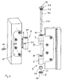
- the band 100 according to the invention shown in the drawing serves the hinged about a hinge axis S connection of a wing 1 on a frame 2. It comprises a first hinge flap 3, which is usually - as in the embodiment shown in the drawing - provided for attachment to the frame 2 and therefore also referred to as "frame hinge tab".
- the attachment serve four self-tapping screws 4, which pass through the first hinge flap 3 in counterbores 5.
- the first hinge flap 3 comprises a fastening part 6 of a flat material, on which two in the direction of the hinge axis S spaced apart first hinge parts 7, 7 'integrally formed by bending the material.
- the first hinge part 7 is also referred to as “upper first hinge part", the hinge part 7 'accordingly also with “lower first hinge part”.
- the strip 100 according to the invention also comprises a second hinge flap 8 which has a second fastening part 9, which in turn is formed from a flat material, and a second hinge part 10 integrally formed thereon (see in particular FIG Fig. 5 ).
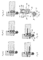
- the second fastening part 9 is mounted in a designated as a whole with 11 tape receiving element. It comprises a front mold part 12 which faces the viewer in the installed state and a rear mold part 13 facing away from the viewer in the mounted state and an angled cover piece 14 which shows the viewer facing side of the front mold part 12 and the narrow hinge side of the tape holding element facing the second hinge part 10 11 with the exception of counterbores 15 for the passage of fastening screws 16 and a slot 17 for the passage of the second fastening part 9 covered (see also Fig. 11 ).
- the front mold part 12 of the tape receiving element 11 comprises a convex contact surface 18, the rear mold part 13 a concave bearing surface 19 which is formed concentrically to the contact surface 18 (s. Fig. 10 ).
- a complementary contact surface 20 complementary to the concave bearing surface and a concave counter-surface 21 complementary to the convex abutment surface 18 are provided, which cooperate slidably with assembled front and rear mold parts 12, 13 (see also FIG Fig. 5 ).
- a tilting movement of the second fastening part 9, the adjustment displacement perpendicular to the hinge axis S in the direction of the arrow J in Fig. 11 serves, as well as a determination of the second fastening part 9 in a desired position is an adjusting screw 22, which is provided in a complementary threaded bore 23 in a projection 24 on the side facing away from the second hinge part 10 edge of the second fastening part 9.
- the adjusting screw 22 is supported with its two ends on inner sides 25, 25 ', which are formed on the front and rear mold parts 12, 13.
- a through-bore 26 is provided which extends through the cover piece 14 and the front molded part 12.
- a pre-assembly of the two mold parts 12, 13 and the Abdeck schizophrenias 14 with the second hinge flap 8 takes place by first the front mold part 12 is placed on the Abdeck Gla 14. Subsequently, the second fastening part 9 is inserted into the slot 17 of the Abdeck Anlagens 14 until it is with respect to the receiving chamber 29 in the desired position. Now, the adjusting screw 22 is screwed into the threaded hole 23 until it is on both sides of the Extension 24 protrudes about the same extent. Subsequently, the rear mold part 13 is placed on the second hinge plate 8 with its second fastening part 9 such that the convex counter-contact surface 20 bears against the concave contact surface 19. A fixation of the assembly takes place with the aid of a connecting screw 30, which passes through the rear molding 13 in a bore 31, the second fastening part 9 in a bore 32 and in a provided in the front mold part 12 threaded bore 33 can be screwed.
- a hinge pin 34 is inserted.
- the hinge pin bearing bushes 35, 36, 37 are provided in the hinge parts.
- the hinge pin has at its upper end a flat head 38 with a measure 39 for applying a turning tool.
- the outer diameter of the head 38 corresponds to the outer diameter of the first hinge part 7.
- an external thread 40 is provided, which is complementary to an opening provided at the upper end of the upper first hinge part 7 internal thread 41.
- first and second hinge parts 7, 7 '; 10 For pivotal about the hinge axis S connection of the first and second hinge tabs are when the hinge pin 34, the first and second hinge parts 7, 7 '; 10 brought into a mutually aligned position, the hinge pin 34 inserted from above and finally rotatably operated until the bottom of the head 38 abuts the upper side of the upper, first hinge part 7.
- the hinge pin 34 In order to prevent the hinge pin 34 can be dismantled with the wing closed, it has a reduced diameter portion 42. This The area is located in the mounted state within the second hinge part 10. The latter has a slot 43 through which a clamping fork-like design locking element 44 can be inserted. It is designed such that its prongs rest under the elastic pretension on the outer circumference of the region 42.
- the region 42 has a length which is substantially greater than the thickness of the locking element 44. This has the effect that the second hinge part 10 can be displaced in the direction of the hinge axis S between the upper and lower first hinge parts 7, 7 ', without the belt bolt 34 having to be displaced for this purpose.
- the bearing bush 36 of the lower first hinge part 7 ' is designed as an adjusting sleeve 45, which is supported with its lower edge 46 on an adjusting spindle 47, which from below into a provided in the lower, first hinge part 7' internal thread is rotatable.
- the adjusting sleeve 45 comprises at its upper end a radially projecting collar 48 whose outer diameter corresponds approximately to the outer diameter of the lower first hinge part 7 '. It carries a cap 49 whose cylindrical lateral surface 50 has an inner circumference such that the cap 49 rests against the lower first hinge part 7 'under frictional engagement.
- the cap 49 has a projection 51 projecting from the circumferential collar forming a surface 51, on which a scale 52 for indicating the adjustment position in the direction of the hinge axis S is provided.
- the cap 49 has downwardly directed recesses 53, which engage in complementary, provided on the collar 48 recesses 54, so as to effect a security against rotation between the cap 49 and the adjusting sleeve 45.
- the provided on the upper first hinge part 7 bushing 37 has a cap 55, the outer shape of which corresponds to that of the cap 49 and the description thereof is thus made.
- the cap 55 comprises - as in particular in Fig. 7 is recognizable - inner projections 56, via which the cap 55 frictionally cooperates with the hinge pin 34. Due to this measure, the bearing sleeve 37 is taken up to the stop on the underside of the upper first hinge part 7 when pulling the hinge pin and so the distance between the bearing sleeves 36, 37 increases, whereby insertion of the second hinge part 10 is facilitated.
- a threaded cap 57 is provided with an adjusting screw 47 corresponding external thread 58 which is screwed after completion of the adjustment in the lower first hinge part 7 '.
Abstract
Description
Die Erfindung betrifft ein Band zur um eine Scharnierachse schwenkbaren Verbindung eines Flügels mit einem Rahmen, mit einem ersten, ein erstes Befestigungsteil und ein erstes Scharnierteil aufweisenden Bandlappen, der um die Scharnierachse schwenkbar mit einem ein zweites Befestigungsteil und ein zweites Scharnierteil aufweisenden zweiten Bandlappen verbunden ist, dessen zweites Scharnierteil um eine etwa parallel zur Scharnierachse verlaufende Kippachse kippbar in einem Bandaufnahmeelement angeordnet ist.The invention relates to a band for pivotally about a hinge axis connection of a wing with a frame, having a first, a first fastening part and a first hinge part having hinge tabs which is pivotally connected to the hinge axis with a second fastening part and a second hinge part having second hinge tab whose second hinge part is arranged to be tiltable about a tilt axis extending approximately parallel to the hinge axis in a belt receiving element.
Ein derartiges Band ist beispielsweise aus der
Nachteilig ist bei dem aus der
Der Erfindung liegt die Aufgabe zugrunde, ein bezüglich der vorgenannten Nachteile verbessertes Band zu schaffen.The invention has for its object to provide a respect to the aforementioned disadvantages improved band.
Diese Aufgabe wird durch das in Anspruch 1 wiedergegebene Band gelöst. Die Kippachse wird bei dem erfindungsgemäßen Band von zumindest einer in Richtung der Kippachse gesehen kreissegmentförmig gekrümmten, an dem Bandaufnahmeelement vorgesehenen Anlagefläche definiert, die an einer an dem zweiten Befestigungsteil vorgesehenen, etwa komplementär gekrümmten Gegenanlagefläche anliegt. Aufgrund der flächigen Anlage wird eine zumindest nahezu spielfreie Lagerung des zweiten Befestigungsteils in dem Bandaufnahmeelement auch während eines Justiervorgangs erzielt. Die Verkippung des zweiten Befestigungsteils findet nun um eine Kippachse statt, die senkrecht von dem zweiten Befestigungsteil etwa um den Krümmungsradius der Anlagefläche beabstandet ist. Hierdurch kann die Länge der regelmäßig unerwünschten, senkrecht zur Justierrichtung auftretenden Bewegungskomponente reduziert werden, so dass die mit dem erfindungsgemäßen Band erzielbare Justiergenauigkeit gegenüber dem vorgenannten Stand der Technik verbessert ist.This object is achieved by the reproduced in
Bei einer bevorzugten Ausführungsform des erfindungsgemäßen Bandes sind an dem zweiten Befestigungsteil zwei einen konstanten Abstand zueinander aufweisende Gegenanlageflächen und an dem Bandaufnahmeelement zwei zu den Gegenanlageflächen komplementäre Anlageflächen vorgesehen, deren Abstand zueinander etwa dem Abstand der Gegenanlageflächen zueinander entspricht. Die Anlagen und Gegenanlageflächen sind mit anderen Worten konzentrisch angeordnet, so dass das Befestigungsteil unter beidseitigem, flächigem Kontakt um die Kippachse verlagert werden kann. Diese Ausgestaltung zeichnet sich daher durch eine besondere Spielarmut aus.In a preferred embodiment of the tape according to the invention two opposing contact surfaces having a constant distance from each other and provided on the tape receiving element two complementary to the counter-bearing surfaces contact surfaces whose distance from each other corresponds approximately to the distance of the counter-contact surfaces to each other. In other words, the systems and counter-bearing surfaces are arranged concentrically, so that the fastening part can be displaced around the tilting axis under two-sided, planar contact. This embodiment is therefore characterized by a particular lack of play.
Es hat sich gezeigt, dass bei einer Dicke des Bandaufnahmeelements, die die üblicherweise im Falle von Türflügeln wünschenswert erachteten Justierlängen von +/- 5mm aus der Mittellage noch ermöglicht, eine in den meisten Fällen ausreichende, wenn auch nicht vollständige Kompensation der zur Justierrichtung senkrechten Bewegungskomponente erzielt wird, wenn die Anlage- und Gegenanlageflächen Krümmungsradien aufweisen, die bewirken, dass die Kippachse außerhalb des zweiten Befestigungsteils liegt. Die Länge der unerwünschten Bewegungskomponente senkrecht zur Justierungsrichtung kann durch Auswahl der Krümmungsradien beeinflusst werden.It has been found that, with a thickness of the tape receiving element, the adjustment lengths of, which are normally considered desirable in the case of door leaves +/- 5mm from the central position still allows, in most cases, sufficient, although not complete compensation of the direction perpendicular to the adjustment movement component is achieved when the abutment and counter-abutment surfaces have radii of curvature, which cause the tilt axis is outside the second attachment part , The length of the unwanted component of motion perpendicular to the direction of adjustment can be influenced by selecting the radii of curvature.
Die mit dem erfindungsgemäßen Band erzielbaren Vorteile sind unabhängig von den Mitteln, die zum Bewirken der Kippbewegung des zweiten Befestigungsteils um die Kippachse vorgesehen sind. Wegen der Einfachheit der Herstellung und der präzisen Betätigbarkeit weist eine besonders bevorzugte Ausführungsform des erfindungsgemäßen Bandes hierzu eine Verstellschraube auf, die - besonders bevorzugt - in einer Gewindebohrung des zweiten Befestigungsteils aufgenommen ist und sich mit ihren beiden Enden an Innenseiten des Bandaufnahmeelements abstützt. Sind die Gewindesteigungen der Verstellschraube und der Gewindebohrung selbsthemmend gewählt, so sind - auch wegen der zumindest nahezu spielfreien Lagerung des zweiten Befestigungsteils in dem Bandaufnahmeelement - keine weiteren Maßnahmen erforderlich, um das zweite Befestigungsteil in einer durch Drehbetätigung der Verstellschraube erzielten Justierstellung zu fixieren.The achievable with the tape according to the invention advantages are independent of the means which are provided for effecting the tilting movement of the second fastening part about the tilting axis. Because of the ease of manufacture and the precise operability, a particularly preferred embodiment of the tape according to the invention for this purpose an adjusting screw, which - is particularly preferred - in a threaded bore of the second fastening part is taken and is supported with its two ends to inner sides of the tape receiving element. If the thread pitches of the adjusting screw and the threaded bore are chosen to be self-locking, then no further measures are required to fix the second fastening part in an adjustment position achieved by rotary actuation of the adjusting screw, also because of the at least almost play-free mounting of the second fastening part in the band receiving element.
Die Verstellschraube ist - besonders bevorzugt - an dem von dem zweiten Scharnierteil entfernten Endbereich des zweiten Befestigungsteils vorgesehen. Bei dieser besonders bevorzugten Ausführungsform des erfindungsgemäßen Bandes befindet sich mit anderen Worten die Verstellschraube nicht zwischen der die Kippachse definierenden Lagerung des zweiten Befestigungsteils und dem zweiten Scharnierteil, sondern die die Kippachse definierende Lagerung erfolgt zwischen der Verstellschraube und dem zweiten Scharnierteil. Das zweite Befestigungsteil ist also als eine Art um die Kippachse verschwenkbare Wippe ausgebildet, an deren einem Endbereich sich die Verstellschraube, an deren anderen Ende sich das zweite Scharnierteil befinden. Aufgrund dieser Maßnahme ist die Entfernung zwischen der Scharnierachse und der Kippachse reduziert, so dass von dem zweiten Scharnierteil aufgenommene Kräfte über einen kürzeren Hebel in das Bandaufnahmeelement eingeleitet werden als beim Stand der Technik.The adjusting screw is - particularly preferably - provided on the remote from the second hinge part end portion of the second fastening part. In other words, in this particularly preferred embodiment of the band according to the invention, the adjusting screw is not located between the bearing of the second fastening part defining the tilting axis and the second hinge part, but the bearing defining the tilting axis takes place between the adjusting screw and the second hinge part. The second attachment part is thus formed as a kind of rocker pivotable about the tilt axis, at one end of which the adjusting screw, at the other end of which the second hinge part are located. By virtue of this measure, the distance between the hinge axis and the tilting axis is reduced, so that forces absorbed by the second hinge part are introduced into the tape receiving element via a shorter lever than in the prior art.
Bei einer ganz besonders bevorzugten Ausführungsform des erfindungsgemäßen Bandes ist das Bandaufnahmeelement in einer zur Kippachse parallel und zwischen den Anlageflächen verlaufenden Trennebene geteilt ausgebildet. Eine Vormontage des zweiten Bandlappens, der Verstellschraube und des Bandaufnahmeelements zu einer Baugruppe kann dann auf einfache Weise erfolgen, indem zunächst die Verstellschraube in die Gewindebohrung des zweiten Befestigungsteils des vorgefertigten zweiten Bandlappens eingedreht, dieser in ein Teil des Bandaufnahmeelements eingelegt und dann das andere Teil montiert wird.In a very particularly preferred embodiment of the tape according to the invention, the tape receiving element is formed in a direction parallel to the tilting axis and extending parallel between the contact surfaces dividing plane. A pre-assembly of the second hinge, the adjusting screw and the tape receiving member to a module can then be done in a simple manner by first screwed the adjusting screw into the threaded bore of the second mounting part of the prefabricated second hinge strap, this inserted in a part of the tape receiving element and then mounted the other part becomes.
Bei einer Weiterbildung des erfindungsgemäßen Bandes wird die Scharnierachse von einem in die ersten und zweiten Scharnierteile eingreifenden Bandbolzen definiert. Dieser weist einen Bereich reduzierten Durchmessers auf. In zumindest einem der ersten oder zweiten Scharnierteile ist eine Aufnahme vorgesehen, in die bei geöffnetem Flügel ein Verriegelungselement einbringbar ist, welches im eingebrachten Zustand mit dem Bereich reduzierten Durchmessers zusammenwirkt, derart, dass der Bandbolzen nicht ohne vorheriges Ausbringen des Verriegelungselements aus den ersten und zweiten Scharnierteilen herausgezogen werden kann. Ein Lösen der Verbindung zwischen dem ersten und dem zweiten Bandlappen ist daher zerstörungsfrei nur nach Entnahme des Verriegelungselements bei geöffnetem Flügel möglich, wodurch ein unbefugtes "Aushängen" eines geschlossenen Flügels wesentlich erschwert ist.In a further development of the band according to the invention, the hinge axis is defined by a band pin engaging in the first and second hinge parts. This has a reduced diameter area. In at least one of the first or second hinge parts, a receptacle is provided, into which a locking element can be introduced when the wing is open, which interacts with the area of reduced diameter in the inserted state, such that the hinge pin does not work without first deploying the locking element of the first and second Hinge parts can be pulled out. A release of the connection between the first and the second hinge flap is therefore possible nondestructive only after removal of the locking element with the wing open, whereby an unauthorized "unhooking" a closed wing is much more difficult.
Der vorbeschriebenen Ausgestaltung zur Sicherung des geschlossenen Flügels gegen unbefugtes Aushängen kommt erfinderische Bedeutung unabhängig davon zu, ob es sich bei dem Band um ein solches mit Bandaufnahmeelement der vorbeschriebenen Art oder um ein konventionelles Band handelt.The above-described embodiment for securing the closed wing against unauthorized unhooking is inventive importance regardless of whether it is the tape with such a tape recording element of the type described above or a conventional tape.
Das Verriegelungselement ist vorzugsweise klemmgabelartig ausgebildet derart, dass im eingeschobenen Zustand die Gabeln vorzugsweise unter einer elastischen Vorspannung an dem Bereich reduzierten Durchmessers anliegen. Ein derart ausgestaltetes Verriegelungselement kann einfach und kostengünstig durch Stanzen aus Flachmaterial hergestellt werden, als Aufnahme dient dann ein einfach herstellbarer Schlitz, dessen Querschnitt an denjenigen des Verriegelungselements angepasst ist.The locking element is preferably designed like a forked fork in such a way that in the inserted state, the forks preferably rest against the region of reduced diameter under elastic pretensioning. Such configured locking element can be easily and inexpensively manufactured by punching from flat material, as a recording then serves a simple producible slot whose cross section is adapted to those of the locking element.
Der Bandbolzen weist vorzugsweise an einem Endbereich ein Außengewinde und als Scharnierteil ein komplementäres Innengewinde auf. Der Bandbolzen wird dann durch Eindrehen in seine gewünschte Position gebracht und in dieser gehalten.The hinge pin preferably has an external thread at one end region and a complementary internal thread as the hinge part. The hinge pin is then brought by screwing in its desired position and held in this.
Bei einer ebenfalls bevorzugten Ausführungsform des erfindungsgemäßen Bandes ist an einem Scharnierteil ein Innengewinde vorgesehen, in welches eine ein komplementäres Außengewinde aufweisende Verstellspindel eindrehbar ist. Ferner ist eine Verstellhülse vorgesehen, die sich mit einem Ende auf der Verstellspindel abstützt und deren anderes Ende an einer Stirnseite des anderen Scharnierteils anliegt. Durch Drehbetätigung der Verstellspindel lässt sich die Anlagefläche in Richtung der Scharnierachse verlagern und das Band in dieser Richtung justieren. An der Verstellhülse ist vorzugsweise ein Umfangskragen vorgesehen, der den äußeren Umfang des einen Scharnierteils zumindest teilweise überdeckt, um so ein unzerklüftetes äußeres Erscheinungsbild unabhängig von der Justierstellung zu bewirken. An dem Umfangskragen ist eine vorstehende Lasche mit einer Skalierung auf deren Oberfläche vorgesehen, mittels welcher die momentane Justierstellung in Richtung der Scharnierachse abgelesen werden kann. Diese Maßnahme, der auch bei Bändern vorbekannter Art eigene erfinderische Bedeutung zukommt, erleichtert es beispielsweise, eine einmal gefundene Justierstellung nach einem Ausbau des Flügels zu reproduzieren.In a likewise preferred embodiment of the band according to the invention an internal thread is provided on a hinge part, in which a complementary external thread having adjusting screw can be screwed. Further, an adjusting sleeve is provided, which is supported with one end on the adjusting spindle and abuts the other end to an end face of the other hinge part. By rotating the adjustment spindle, the contact surface can be displaced in the direction of the hinge axis and the belt adjusted in this direction. A circumferential collar is preferably provided on the adjusting sleeve which at least partially covers the outer circumference of the one hinge part so as to bring about an unjointed external appearance independently of the adjustment position. On the circumferential collar a projecting tab is provided with a scale on the surface thereof, by means of which the instantaneous adjustment position can be read in the direction of the hinge axis. This measure, which also has its own inventive significance in tapes of known type, makes it easier, for example, to reproduce a once found adjustment position after removal of the wing.
Insbesondere wenn es sich bei dem Band um ein sogenanntes dreiteiliges Band handelt, bei welchem der erste Bandlappen zwei in Richtung der Scharnierachse Abstand voneinander belassende erste Scharnierteile umfasst, nachfolgend auch mit "oberem" und "unterem" ersten Scharnierteil bezeichnet, und welches für eine Verwendung mit etwa senkrecht verlaufender Scharnierachse vorgesehen ist, sind die Verstellhülsen vorzugsweise an dem unteren, ersten Scharnierteil und an dem oberen, ersten Scharnierteil eine Lagerhülse vorgesehen. Letztere weist einen Umfangskragen auf, der demjenigen der Verstellhülse zumindest im wesentlichen entspricht.In particular, when the band is a so-called three-piece band, in which the first band flap comprises two first hinge parts leaving the hinge axis spaced from each other, hereinafter also referred to as "upper" and "lower" first hinge part, and which is for use is provided with approximately perpendicular hinge axis, the adjusting sleeves are preferably provided at the lower, first hinge part and at the upper, first hinge part a bearing sleeve. The latter has a peripheral collar which at least substantially corresponds to that of the adjusting sleeve.
Aufgrund dieser Maßnahme wird auch bei einem dreiteiligen Band vermieden, dass die jeweilige Justierstellung in Richtung der Scharnierachse durch unterschiedliche Spaltmaße zwischen den Stirnseiten der oberen und unteren ersten Scharnierteile und den jeweils zugewandten Stirnseiten des zweiten Scharnierteils optisch erkennbar ist.Due to this measure, it is avoided even with a three-part band, that the respective adjustment position in the direction of the hinge axis by different gap dimensions between the end faces of the upper and lower first hinge parts and the respective facing end sides of the second hinge part is optically recognizable.
Die Verstellhülse ist vorzugsweise derart ausgebildet, dass sie reibschlüssig mit dem unteren ersten Scharnierteil zusammenwirkt. Unter "reibschlüssig" ist zu verstehen, dass sie unter Überwindung einer Reibkraft Beschädigungsfrei auf das untere erste Scharnierteil aufgesetzt und auch wieder abgenommen werden kann, sie jedoch verliersicher auf dem unteren ersten Scharnierteil gelagert ist und auch bei einem Ziehen des Bandbolzens zum Zwecke der Trennung der Verbindung zwischen den beiden Bandlappen auf dem unteren ersten Scharnierteil verbleibt.The adjusting sleeve is preferably designed such that it interacts frictionally with the lower first hinge part. By "frictionally engaged" is to be understood that they can be placed damaging over the lower first hinge part overcoming friction and also removed again, but it is stored captive on the lower first hinge part and also when pulling the hinge pin for the purpose of separation Connection between the two hinge tabs on the lower first hinge part remains.
Die Lagerhülse ist vorzugsweise derart ausgebildet, dass sie reibschlüssig mit dem Bandbolzen zusammenwirkt. Wird dieser zum Zwecke des Lösens der Verbindung zwischen den beiden Bandlappen nach oben verlagert, so nimmt er die Lagerhülse mit, bis sie an der unteren Stirnseite des oberen, ersten Scharnierteils anliegt. Es vergrößert sich hierdurch der Abstand der einander zugewandten Stirnseiten der Verstellhülse und der Lagerhülse, so dass ein Wiedereinsetzen des zweiten Scharnierteils vereinfacht ist.The bearing sleeve is preferably designed such that it interacts frictionally with the hinge pin. If this is displaced upward for the purpose of releasing the connection between the two hinge lugs, then it takes the bearing sleeve with it until it bears against the lower end face of the upper, first hinge part. This increases the distance between the mutually facing end faces of the adjusting sleeve and the bearing sleeve, so that re-insertion of the second hinge part is simplified.
Anhand der beigefügten Zeichnung soll nun ein Ausführungsbeispiel des erfindungsgemäßen Bandes im Einzelnen erläutert werden. Es zeigen:
- Fig.1
- eine Ansicht senkrecht zur Scharnierachse der im montierten Zustand dem Betrachter abgewandten Seite (auch "Rückseite" bezeichnet) dieses Bandes;
- Fig. 2
- die im montierten Zustand dem Betrachter zugewandte Seite dieses Bandes in einer perspektivischen Ansicht;
- Fig. 3
- das Band in einer Ansicht gemäß
Fig. 2 in an einem schematisch dargestellten Rahmen und einem schematisch dargestellten Flügel montierten Zustand; - Fig. 4
- eine
Fig. 3 entsprechende Ansicht, jedoch im nach Ausbringen des Verriegelungselements und des Bandbolzens getrennten Zustand der beiden Bandlappen; - Fig. 5
- eine perspektivische Explosionsdarstellung des zweiten Bandlappens und des Bandaufnahmeelements;
- Fig. 6a) bis d)
- verschiedene Ansichten des ersten Bandlappens mit Verstellund Lagerhülsen;
- Fig. 7
- einen Schnitt in Richtung der Scharnierachse durch das obere, erste Scharnierteil und das zweite Scharnierteil im miteinander verbundenen Zustand;
- Fig. 8a) bis c)
- Schnitte gemäß Schnittlinie VIII in
Fig. 3 , jedoch bei geschlossenem Flügel in verschiedenen Justierstellungen senkrecht zur Scharnierachse; - Fig. 9
- einen Schnitt gemäß Schnittlinie IX in
Fig. 3 , wiederum bei geschlossenem Flügel; - Fig. 10
- eine
Fig. 9 entsprechende Ansicht gemäß Schnittlinie X inFig. 3 ; - Fig. 11
- eine vergrößerte Darstellung der Ansicht gemäß
Fig. 8c ) des zweiten Bandlappens und des Bandaufnahmeelements sowie - Fig. 12a) bis c)
- einen Längsschnitt dieses Bandes durch die Scharnierachse bei geschlossenem Flügel in verschiedenen Justierstellungen in Scharnierachsenrichtung.
- Fig.1
- a view perpendicular to the hinge axis of the viewer in the mounted state away from the side (also called "back") of this band;
- Fig. 2
- in the assembled state the viewer facing side of this band in a perspective view;
- Fig. 3
- the band in a view according to
Fig. 2 in mounted on a schematically illustrated frame and a schematically illustrated wing state; - Fig. 4
- a
Fig. 3 corresponding view, but in after disengagement of the locking element and the hinge pin separate state of the two hinge tabs; - Fig. 5
- an exploded perspective view of the second hinge strap and the tape receiving member;
- Fig. 6a) to d)
- different views of the first hinge strap with adjusting and bearing sleeves;
- Fig. 7
- a section in the direction of the hinge axis through the upper, first hinge part and the second hinge part in the interconnected state;
- 8a) to c)
- Sections according to section line VIII in
Fig. 3 , but with the sash closed in different adjustment positions perpendicular to the hinge axis; - Fig. 9
- a section along section line IX in
Fig. 3 , again with the wing closed; - Fig. 10
- a
Fig. 9 corresponding view according to section line X inFig. 3 ; - Fig. 11
- an enlarged view of the view according to
Fig. 8c ) of the second hinge and the tape receiving element and - Fig. 12a) to c)
- a longitudinal section of this band through the hinge axis with the wing closed in different adjustment positions in hinge axis direction.
Das in der Zeichnung dargestellte erfindungsgemäße Band 100 dient der um eine Scharnierachse S scharniergelenkigen Verbindung eines Flügels 1 an einem Rahmen 2. Es umfasst einen ersten Bandlappen 3, der meist - wie in dem in der Zeichnung dargestellten Ausführungsbeispiel - zur Anbringung am Rahmen 2 vorgesehen ist und daher auch als "Rahmenbandlappen" bezeichnet wird. Der Befestigung dienen vier selbstschneidende Befestigungsschrauben 4, welche den ersten Bandlappen 3 in Senkbohrungen 5 durchsetzen.The
Der erste Bandlappen 3 umfasst ein Befestigungsteil 6 aus einem Flachwerkstoff, an welchen zwei in Richtung der Scharnierachse S voneinander beabstandete erste Scharnierteile 7, 7' einstückig durch Biegen des Werkstoffs angeformt sind. Das erste Scharnierteil 7 wird auch als "oberes erstes Scharnierteil", das Scharnierteil 7' dementsprechend auch mit "unteres erstes Scharnierteil" bezeichnet.The
Das erfindungsgemäße Band 100 umfasst darüber hinaus einen zweiten Bandlappen 8, welcher ein wiederum aus einem Flachmaterial geformtes zweites Befestigungsteil 9 und ein daran einstückig angeformtes zweites Scharnierteil 10 aufweist (s. insbesondere
Das zweite Befestigungsteil 9 ist in einem als Ganzes mit 11 bezeichneten Bandaufnahmeelement gelagert. Es umfasst ein dem Betrachter im montierten Zustand zugewandtes vorderes Formteil 12 und ein im montierten Zustand dem Betrachter abgewandtes, hinteres Formteil 13 sowie ein abgewinkeltes Abdeckstück 14, welches die dem Betrachter zugewandte Seite des vorderen Formteils 12 sowie die dem zweiten Scharnierteil 10 zugewandte Schmalseite des Bandaufnahmeelements 11 mit Ausnahme von Senkbohrungen 15 zum Durchtritt von Befestigungsschrauben 16 und einem Schlitz 17 zum Durchtritt des zweiten Befestigungsteils 9 überdeckt (s. auch
Das vordere Formteil 12 des Bandaufnahmeelements 11 umfasst eine konvexe Anlagefläche 18, das hintere Formteil 13 eine konkave Anlagefläche 19, die konzentrisch zu der Anlagefläche 18 ausgebildet ist (s.
An dem zweiten Befestigungsteil 9 sind eine zu der konkaven Anlagefläche komplementär ausgebildete Gegenanlagefläche 20 und eine zu der konvex ausgebildeten Anlagefläche 18 komplementär ausgebildete konkave Gegenanlagefläche 21 vorgesehen, welche bei zusammengefügten vorderen und hinteren Formteilen 12, 13 gleitend zusammenwirken (s. auch
Eine Kippbewegung des zweiten Befestigungsteils 9, die einer Justierungsverlagerung senkrecht zur Scharnierachse S in Richtung des Pfeils J in
Um an die Verstellschraube 22 ein Werkzeug zur Drehbetätigung ansetzen zu können, ist eine Durchgangsbohrung 26 vorgesehen, die sich durch das Abdeckstück 14 und das vordere Formteil 12 erstreckt.In order to be able to apply a tool for rotational actuation to the adjusting screw 22, a through-
Wie insbesondere aus
Eine Vormontage der beiden Formteile 12, 13 und des Abdeckstücks 14 mit dem zweiten Bandlappen 8 erfolgt, indem zunächst das vordere Formteil 12 auf das Abdeckstück 14 aufgelegt wird. Anschließend wird das zweite Befestigungsteil 9 in den Schlitz 17 des Abdeckstücks 14 eingeschoben, bis es sich bezüglich der Aufnahmekammer 29 in der gewünschten Position befindet. Nun wird die Verstellschraube 22 in die Gewindebohrung 23 eingedreht, bis sie auf beiden Seiten des Fortsatzes 24 etwa in demselben Maße herausragt. Anschließend wird das hintere Formteil 13 derart auf dem zweiten Bandlappen 8 mit seinem zweiten Befestigungsteil 9 aufgelegt, dass die konvexe Gegenanlagefläche 20 an der konkaven Anlagefläche 19 anliegt. Eine Fixierung der Baugruppe erfolgt mit Hilfe einer Verbindungsschraube 30, die das hintere Formteil 13 in einer Bohrung 31, das zweite Befestigungsteil 9 in einer Bohrung 32 durchsetzt und in eine in dem vorderen Formteil 12 vorgesehene Gewindebohrung 33 eindrehbar ist.A pre-assembly of the two
Die Befestigung der so vorbereiteten Baugruppe (bei dem in der Zeichnung dargestellten Ausführungsbeispiel am Flügel 1) erfolgt mit Hilfe der selbstschneidenden Befestigungsschrauben 16.The attachment of the thus prepared assembly (in the embodiment shown in the drawing on the wing 1) by means of self-tapping screws 16th
Wie insbesondere in
Der Bandbolzen weist an seinem oberen Ende einen flachen Kopf 38 mit einer Maßnahme 39 zum Ansetzen eines Drehwerkzeugs auf. Der Außendurchmesser des Kopfes 38 entspricht dem Außendurchmesser des ersten Scharnierteils 7. Unterhalb des Kopfes 38 ist ein Außengewinde 40 vorgesehen, welches komplementär zu einem am oberen Ende des oberen ersten Scharnierteils 7 vorgesehenen Innengewinde 41 ausgebildet ist.The hinge pin has at its upper end a
Zur um die Scharnierachse S verschwenkbaren Verbindung der ersten und zweiten Bandlappen werden bei gezogenem Bandbolzen 34 die ersten und zweiten Scharnierteile 7, 7'; 10 in eine zueinander fluchtende Position gebracht, der Bandbolzen 34 von oben eingeführt und schließlich drehbetätigt, bis die Unterseite des Kopfes 38 an der Oberseite des oberen, ersten Scharnierteils 7 anliegt.For pivotal about the hinge axis S connection of the first and second hinge tabs are when the
Um zu verhindern, dass der Bandbolzen 34 bei geschlossenem Flügel demontiert werden kann, weist er einen Bereich 42 reduzierten Durchmessers auf. Dieser Bereich befindet sich im montierten Zustand innerhalb des zweiten Scharnierteils 10. Letzteres weist einen Schlitz 43 auf, durch den ein klemmgabelartig ausgebildetes Verriegelungselement 44 einschiebbar ist. Es ist derart ausgebildet, dass seine Zinken unter einer elastischen Vorspannung an dem Außenumfang des Bereichs 42 anliegen.In order to prevent the
Wie in
Hierzu weisen die einander zugewandten Seiten der oberen und unteren ersten Scharnierteile einen Abstand auf, der größer als die Länge des zweiten Scharnierteils 10 ist. Zwecks Justierung in Richtung der Scharnierachse S ist die Lagerbuchse 36 des unteren ersten Scharnierteils 7' als Verstellhülse 45 ausgebildet, die sich mit ihrem unteren Rand 46 auf einer Verstellspindel 47 abstützt, welche von unten in ein in dem unteren, ersten Scharnierteil 7' vorgesehenen Innengewinde eindrehbar ist.For this purpose, the mutually facing sides of the upper and lower first hinge parts at a distance which is greater than the length of the
Die Verstellhülse 45 umfasst an ihrem oberen Ende einen radial überstehenden Kragen 48, dessen Außendurchmesser etwa dem Außendurchmesser des unteren ersten Scharnierteils 7' entspricht. Er trägt eine Kappe 49, deren zylindrische Mantelfläche 50 einen derartigen Innenumfang aufweist, dass die Kappe 49 unter einem Reibschluss an dem unteren ersten Scharnierteil 7' anliegt.The adjusting
Die Kappe 49 weist eine aus der einen Umfangskragen bildenden Mantelfläche 50 vorstehende Lasche 51 auf, an welcher eine Skalierung 52 zum Anzeigen der Justierstellung in Richtung der Scharnierachse S vorgesehen ist.The
Die Kappe 49 weist nach unten gerichtete Ausbuchtungen 53 auf, die in komplementäre, an dem Kragen 48 vorgesehene Ausnehmungen 54 eingreifen, um so eine Verdrehsicherheit zwischen der Kappe 49 und der Verstellhülse 45 zu bewirken.The
Die an dem oberen ersten Scharnierteil 7 vorgesehene Lagerbuchse 37 weist eine Kappe 55 auf, deren äußere Gestalt derjenigen der Kappe 49 entspricht und auf deren Beschreibung somit verwiesen wird. Die Kappe 55 umfasst - wie insbesondere in
Eine Justierung des zweiten Bandlappens 8 zum ersten Bandlappen 3 in Richtung der Scharnierachse S kann - wie insbesondere anhand von
Zur Verbesserung des optischen Eindrucks ist eine Gewindekappe 57 mit einem der Verstellspindel 47 entsprechenden Außengewinde 58 vorgesehen, die nach Abschluss des Justiervorgangs in das untere erste Scharnierteil 7' eingeschraubt wird.To improve the visual impression, a threaded
- 100100
- Bandtape
- 11
- Flügelwing
- 22
- Rahmenframe
- 33
- erster Bandlappenfirst hinge
- 44
- Befestigungsschraubenmounting screws
- 55
- Senkbohrungencountersunk
- 66
- erstes Befestigungsteilfirst fastening part
- 7, 7'7, 7 '
- erste Scharnierteilefirst hinge parts
- 88th
- zweiter Bandlappensecond hinge flap
- 99
- zweites Befestigungsteilsecond fastening part
- 1010
- zweites Scharnierteilsecond hinge part
- 1111
- BandaufnahmeelementTape hub
- 1212
- vorderes Formteilfront molding
- 1313
- hinteres Formteilrear molding
- 1414
- Abdeckstückcover piece
- 1515
- Senkbohrungencountersunk
- 1616
- Befestigungsschraubenmounting screws
- 1717
- Schlitzslot
- 1818
- konvexe Anlageflächeconvex contact surface
- 1919
- konkave Anlageflächeconcave contact surface
- 2020
- konvexe Gegenanlageflächeconvex counter-bearing surface
- 2121
- konkave Gegenanlageflächeconcave counter-bearing surface
- 2222
- Verstellschraubeadjusting
- 2323
- Gewindebohrungthreaded hole
- 2424
- Fortsatzextension
- 25, 25'25, 25 '
- Innenseiteninsides
- 2626
- DurchgangsbohrungThrough Hole
- 27, 27'27, 27 '
- Schmalseitennarrow sides
- 28, 28'28, 28 '
- Rändermargins
- 2929
- Aufnahmekammerreceiving chamber
- 3030
- Verbindungsschraubeconnecting screw
- 3131
- Bohrungdrilling
- 3232
- Bohrungdrilling
- 3333
- Gewindebohrungthreaded hole
- 3434
- Bandbolzenhinge bolts
- 3535
- Lagerbuchsebearing bush
- 3636
- Lagerbuchsebearing bush
- 3737
- Lagerbuchsebearing bush
- 3838
- Kopfhead
- 3939
- Maßnahmemeasure
- 4040
- Außengewindeexternal thread
- 4141
- Innengewindeinner thread
- 4242
- BereichArea
- 4343
- Schlitzslot
- 4444
- Verriegelungselementlocking element
- 4545
- Verstellhülseadjusting sleeve
- 4646
- Randedge
- 4747
- Verstellspindeladjusting spindle
- 4848
- Kragencollar
- 4949
- Kappecap
- 5050
- Mantelflächelateral surface
- 5151
- Lascheflap
- 5252
- Skalierungscaling
- 5353
- Ausbuchtungenbulges
- 5454
- Ausnehmungenrecesses
- 5555
- Kappecap
- 5656
- Vorsprüngeprojections
- 5757
- Gewindekappethreaded cap
- 5858
- Gewindethread
- JJ
- Justierungsrichtungadjustment direction
- KK
- Kippachsetilt axis
- SS
- Scharnierachsehinge axis
Claims (14)
mit einem ersten, ein erstes Befestigungsteil (6) und ein erstes Scharnierteil (7, 7') aufweisenden ersten Bandlappen (3), der um die Scharnierachse (S) schwenkbar mit einem ein zweites Befestigungsteil (9) und ein zweites Scharnierteil (10) aufweisenden, zweiten Bandlappen (8) verbunden ist, dessen zweites Scharnierteil (10) um eine etwa parallel zur Scharnierachse (S) verlaufende Kippachse (K) kippbar in einem Bandaufnahmeelement (11) angeordnet ist,
dadurch gekennzeichnet,
dass die Kippachse (K) von zumindest einer in Richtung der Kippachse (K) gesehen kreissegmentförmig gekrümmten, an dem Bandaufnahmeelement (11) vorgesehenen Anlagefläche (18, 19), die an einer an dem zweiten Befestigungsteil vorgesehenen, etwa komplementär gekrümmten Gegenanlagefläche (20, 21) anliegt, definiert ist.Band (100) for pivotable about a hinge axis connection of a wing (1) with a frame (2),
with a first, a first fastening part (6) and a first hinge part (7, 7 ') having first hinge tab (3) pivotable about the hinge axis (S) with a second fastening part (9) and a second hinge part (10) having second hinge tab (8) is connected, the second hinge part (10) about an approximately parallel to the hinge axis (S) extending tilt axis (K) is arranged tiltably in a tape receiving element (11),
characterized,
that the tilting axis (K) of at least one in the direction of the tilting axis (K) seen circular-curved, on the tape receiving member (11) provided abutment surface (18, 19) provided on a provided on the second fastening part, approximately complementary curved counter-bearing surface (20, 21) is present, is defined.
mit einem ersten, ein erstes Befestigungsteil (6) und ein erstes Scharnierteil (7, 7') aufweisenden ersten Bandlappen (3), der um eine Scharnierachse (S) schwenkbar mit einem ein zweites Befestigungsteil (9) und ein zweites Scharnierteil (10) aufweisenden zweiten Bandlappen (8) verbunden ist, insbesondere nach einem der Ansprüche 1 bis 7, wobei die Scharnierachse (S) von einem in die ersten und zweiten Scharnierteile (7, 7'; 10) eingreifenden Bandbolzen (34) definiert wird, der einen Bereich (42) reduzierten Durchmessers aufweist, und wobei ein bei geöffnetem Flügel (1) in eine Aufnahme, die in einem der Scharnierteile vorgesehen ist, einbringbares Verriegelungselement (44) vorgesehen ist, welches im eingebrachten Zustand mit dem Bereich (42) reduzierten Durchmessers zusammenwirkt.Band (100) about a hinge axis (S) pivotable connection of a wing (1) with a frame (2),
with a first, a first fastening part (6) and a first hinge part (7, 7 ') having first hinge tab (3) pivotable about a hinge axis (S) with a second fastening part (9) and a second hinge part (10) in particular according to one of claims 1 to 7, wherein the hinge axis (S) of a in the first and second hinge parts (7, 7 ', 10') engaging hinge pin (34) is defined, the one Having reduced diameter portion (42), and wherein a with open wing (1) in a receptacle which is provided in one of the hinge parts, engageable locking member (44) is provided, which cooperates in the inserted state with the region (42) of reduced diameter ,
dadurch gekennzeichnet,
dass die Verstellhülse (45) an dem unteren, ersten Scharnierteil (7') und das an dem oberen, ersten Scharnierteil (7) eine Lagerhülse (37) vorgesehen ist, die einen Umfangskragen aufweist, der demjenigen der Verstellhülse (45) zumindest im wesentlichen entspricht.A belt according to claim 11, wherein the first hinge tab (2) comprises spaced apart first upper and lower hinge parts (7, 7 ') in the direction of the hinge axis (S) and which is intended for use with an approximately perpendicular hinge axis (S) is
characterized,
in that the adjusting sleeve (45) is provided on the lower, first hinge part (7 ') and that on the upper, first hinge part (7) has a bearing sleeve (37) which has a peripheral collar which is at least essentially that of the adjusting sleeve (45) equivalent.
Applications Claiming Priority (1)
| Application Number | Priority Date | Filing Date | Title |
|---|---|---|---|
| DE202010008013U DE202010008013U1 (en) | 2010-07-08 | 2010-07-08 | Band for pivotable about a hinge axis connection of a wing with a frame |
Publications (1)
| Publication Number | Publication Date |
|---|---|
| EP2405088A2 true EP2405088A2 (en) | 2012-01-11 |
Family
ID=44786934
Family Applications (1)
| Application Number | Title | Priority Date | Filing Date |
|---|---|---|---|
| EP11172541A Withdrawn EP2405088A2 (en) | 2010-07-08 | 2011-07-04 | Hinge for pivotably connecting a leaf with a frame |
Country Status (3)
| Country | Link |
|---|---|
| US (1) | US20120005859A1 (en) |
| EP (1) | EP2405088A2 (en) |
| DE (1) | DE202010008013U1 (en) |
Cited By (1)
| Publication number | Priority date | Publication date | Assignee | Title |
|---|---|---|---|---|
| WO2019034441A1 (en) * | 2017-08-12 | 2019-02-21 | Dirak Dieter Ramsauer Konstruktionselemente Gmbh | Hinge for hangable sheet metal cabinet doors or walls |
Families Citing this family (7)
| Publication number | Priority date | Publication date | Assignee | Title |
|---|---|---|---|---|
| US9605457B2 (en) * | 2008-10-29 | 2017-03-28 | Steven Humble | Three-dimensionally adjustable pivot device |
| EP2586944B1 (en) * | 2011-10-26 | 2016-03-30 | Josef Hasler | Hinge with adjustment elements and adjustment cap for these adjustment elements |
| KR102358739B1 (en) * | 2013-05-20 | 2022-02-08 | 가부시키가이샤 한도오따이 에네루기 켄큐쇼 | Semiconductor device |
| US10760310B2 (en) | 2015-05-12 | 2020-09-01 | Tyler Kessler Holdings Inc. | Replacement door hinges for aligning a door in relation to a door jamb |
| US10246916B1 (en) | 2015-05-12 | 2019-04-02 | Tyler L. Kessler | Door hinges and method for rehanging a door to realign the door in relation to a door jamb |
| JP6914431B2 (en) * | 2017-09-26 | 2021-08-04 | サン−ゴバン パフォーマンス プラスチックス パンプス ゲゼルシャフト ミット ベシュレンクテル ハフツング | Bearings, hinge assemblies, and how to manufacture and use them |
| KR20220099122A (en) | 2019-12-06 | 2022-07-12 | 생-고뱅 퍼포먼스 플라스틱스 코포레이션 | Flanged bearings, assemblies and methods of making and using them |
Citations (1)
| Publication number | Priority date | Publication date | Assignee | Title |
|---|---|---|---|---|
| DE102007019938B3 (en) | 2007-04-27 | 2008-03-27 | Simonswerk, Gmbh | Door hinges e.g. for doors, has lobe and pin arranged on reel and having swiveling storage element |
Family Cites Families (29)
| Publication number | Priority date | Publication date | Assignee | Title |
|---|---|---|---|---|
| JPS4938685Y1 (en) * | 1970-12-14 | 1974-10-23 | ||
| GB8922020D0 (en) * | 1989-09-29 | 1989-11-15 | Bloxwich Eng | Hinges |
| DE9302652U1 (en) * | 1993-02-24 | 1994-08-04 | Hahn Gmbh & Co Kg Dr | Tape for doors, windows and the like |
| US5755011A (en) * | 1995-12-28 | 1998-05-26 | Newell Operating Company | Adjustable hinge |
| US5694665A (en) * | 1996-03-15 | 1997-12-09 | The Stanley Works | Adjustable hinge |
| US5799370A (en) * | 1996-06-12 | 1998-09-01 | The Stanley Works | Adjustable hinge |
| US5881980A (en) * | 1997-06-27 | 1999-03-16 | Knudson; Edward C. | Leg assembly |
| US6058564A (en) * | 1998-02-26 | 2000-05-09 | Newell Operating Company | Adjustable hinge |
| NO309619B1 (en) * | 1998-05-13 | 2001-02-26 | Frip Ab | Snap-type hinge device |
| US6216316B1 (en) * | 1999-06-14 | 2001-04-17 | Dominic R. Errichiello | Hinge |
| US6212734B1 (en) * | 1999-09-13 | 2001-04-10 | Robert R. Commons | Adjustable hinge |
| JP3315389B2 (en) * | 2000-02-08 | 2002-08-19 | 株式会社住建産業 | Hinge |
| NO20014197L (en) * | 2001-08-29 | 2003-03-03 | Frip Ab | Device by hinge |
| SE529138C2 (en) * | 2004-02-09 | 2007-05-08 | Assa Ab | hinge |
| US7331085B2 (en) * | 2004-02-27 | 2008-02-19 | Newell Operating Company | Horizontally adjustable hinge |
| US7293329B2 (en) * | 2004-02-27 | 2007-11-13 | Newell Operating Company | Vertically adjustable hinge |
| US7676887B2 (en) * | 2005-12-22 | 2010-03-16 | Stanley Chung | Two-stage adjustable door hinge |
| ITMI20060041A1 (en) * | 2006-01-12 | 2007-07-13 | Elesa Spa | HINGE WITH ADJUSTMENT BUSHINGS |
| US7694388B2 (en) * | 2006-08-30 | 2010-04-13 | Creative Research & Development, Inc. | Adjustable hinge |
| CA2668686A1 (en) * | 2006-11-06 | 2008-05-15 | Hoppe Holding Ag | Non-handed adjustable hinge set |
| CA2668712A1 (en) * | 2006-11-06 | 2009-03-05 | Hoppe Holding Ag | Adjustable hinge set |
| US8191205B2 (en) * | 2007-12-18 | 2012-06-05 | Liberty Hardware Mfg. Corp. | Door hinge |
| DE202008003694U1 (en) * | 2008-03-17 | 2009-08-06 | Dr. Hahn Gmbh & Co. Kg | Band for pivotally mounting a wing, a door, a window or the like. on a fixed frame |
| US8429794B2 (en) * | 2009-03-25 | 2013-04-30 | Amesbury Group, Inc. | Adjustable door hinge |
| US8099834B2 (en) * | 2009-04-01 | 2012-01-24 | Salvatore Corso | Loose-pin hinge and hinge pin with integrated stop |
| USD636251S1 (en) * | 2009-05-07 | 2011-04-19 | Dr. Hahn Gmbh & Co. Kg | Hinge |
| USD653097S1 (en) * | 2009-12-25 | 2012-01-31 | Sugatsune Kogyo Co., Ltd. | Fitting hinge |
| US8671521B2 (en) * | 2010-05-06 | 2014-03-18 | Robert F. Irwin | Control motion hinge with torsion spring |
| US20110296652A1 (en) * | 2010-06-08 | 2011-12-08 | Betteli Inc Hong Kong | Three-direction adjustable hinge |
-
2010
- 2010-07-08 DE DE202010008013U patent/DE202010008013U1/en not_active Expired - Lifetime
-
2011
- 2011-07-04 US US13/175,895 patent/US20120005859A1/en not_active Abandoned
- 2011-07-04 EP EP11172541A patent/EP2405088A2/en not_active Withdrawn
Patent Citations (1)
| Publication number | Priority date | Publication date | Assignee | Title |
|---|---|---|---|---|
| DE102007019938B3 (en) | 2007-04-27 | 2008-03-27 | Simonswerk, Gmbh | Door hinges e.g. for doors, has lobe and pin arranged on reel and having swiveling storage element |
Cited By (2)
| Publication number | Priority date | Publication date | Assignee | Title |
|---|---|---|---|---|
| WO2019034441A1 (en) * | 2017-08-12 | 2019-02-21 | Dirak Dieter Ramsauer Konstruktionselemente Gmbh | Hinge for hangable sheet metal cabinet doors or walls |
| US11313162B2 (en) | 2017-08-12 | 2022-04-26 | Dirak Dieter Ramsauer Konstruktionselemente Gmbh | Hinge for detachable sheet metal cabinet doors or walls |
Also Published As
| Publication number | Publication date |
|---|---|
| US20120005859A1 (en) | 2012-01-12 |
| DE202010008013U1 (en) | 2011-11-16 |
Similar Documents
| Publication | Publication Date | Title |
|---|---|---|
| EP2405088A2 (en) | Hinge for pivotably connecting a leaf with a frame | |
| EP3529440B1 (en) | Hinge for a door or window | |
| EP2257682B1 (en) | Strap for pivotably fastening a leaf of a door, of a window or the like to a fixed frame | |
| EP1577474A2 (en) | Hinge for concealed mounting between frame and wing | |
| EP1882798A1 (en) | Fitting for door or window | |
| EP0467075B1 (en) | Hinge for doors, windows and the like and positioning element for the guiding part of such a hinge | |
| EP2297418B1 (en) | Hinge | |
| DE2614447C2 (en) | hinge | |
| DE10110311C2 (en) | Hinge with height adjustment screw | |
| EP1128012A2 (en) | Furniture hinge | |
| EP2034109B1 (en) | Rosette with a safety device | |
| EP2084356B1 (en) | Hinge arrangement for doors, windows or the like | |
| DE202006009023U1 (en) | Band with improved adjustment | |
| DE102008036151A1 (en) | Hinge strap with a substructure for attachment to a door leaf | |
| EP1979567A1 (en) | Hinge assembly for the articulated connection of a door leaf, a window casement or similar to a frame | |
| WO2018208238A1 (en) | Retaining device for a front panel of a drawer | |
| DE202008016071U1 (en) | Band for hingedly connecting a wing to a frame | |
| DE102008049828A1 (en) | Belt attachment part | |
| EP1922467B1 (en) | Hinge for doors, windows or the like | |
| WO2010003435A1 (en) | Hinge system | |
| EP4045744B1 (en) | Fitting arrangement | |
| EP0833030B1 (en) | Hinge for doors, windows or similar | |
| DE202007016708U1 (en) | Tape for doors, windows or the like | |
| DE102022204028B3 (en) | Hinged tape for a building door or window | |
| EP1501994A1 (en) | Hinge for windows, doors or the like |
Legal Events
| Date | Code | Title | Description |
|---|---|---|---|
| AK | Designated contracting states |
Kind code of ref document: A2 Designated state(s): AL AT BE BG CH CY CZ DE DK EE ES FI FR GB GR HR HU IE IS IT LI LT LU LV MC MK MT NL NO PL PT RO RS SE SI SK SM TR |
|
| AX | Request for extension of the european patent |
Extension state: BA ME |
|
| PUAI | Public reference made under article 153(3) epc to a published international application that has entered the european phase |
Free format text: ORIGINAL CODE: 0009012 |
|
| STAA | Information on the status of an ep patent application or granted ep patent |
Free format text: STATUS: THE APPLICATION HAS BEEN WITHDRAWN |
|
| 18W | Application withdrawn |
Effective date: 20120424 |