EP2404674A1 - Partikeltrennende Target-Vorrichtung und Verfahren unter Verwendung eines Flussfraktionierungskanals mit mehreren Öffnungen - Google Patents
Partikeltrennende Target-Vorrichtung und Verfahren unter Verwendung eines Flussfraktionierungskanals mit mehreren Öffnungen Download PDFInfo
- Publication number
- EP2404674A1 EP2404674A1 EP11169461A EP11169461A EP2404674A1 EP 2404674 A1 EP2404674 A1 EP 2404674A1 EP 11169461 A EP11169461 A EP 11169461A EP 11169461 A EP11169461 A EP 11169461A EP 2404674 A1 EP2404674 A1 EP 2404674A1
- Authority
- EP
- European Patent Office
- Prior art keywords
- channel
- channels
- flow fractionation
- orifice flow
- moff
- Prior art date
- Legal status (The legal status is an assumption and is not a legal conclusion. Google has not performed a legal analysis and makes no representation as to the accuracy of the status listed.)
- Withdrawn
Links
- 238000005194 fractionation Methods 0.000 title claims abstract description 39
- 238000000034 method Methods 0.000 title claims description 17
- 239000012530 fluid Substances 0.000 claims abstract description 206
- 239000002245 particle Substances 0.000 claims abstract description 162
- 238000000926 separation method Methods 0.000 claims abstract description 115
- 238000004891 communication Methods 0.000 claims abstract description 38
- 230000008602 contraction Effects 0.000 claims abstract description 31
- 239000002699 waste material Substances 0.000 claims description 8
- 239000000523 sample Substances 0.000 description 104
- 210000004027 cell Anatomy 0.000 description 33
- 239000012488 sample solution Substances 0.000 description 25
- 210000004369 blood Anatomy 0.000 description 15
- 239000008280 blood Substances 0.000 description 15
- 238000011084 recovery Methods 0.000 description 13
- 206010028980 Neoplasm Diseases 0.000 description 11
- 201000011510 cancer Diseases 0.000 description 11
- 230000002829 reductive effect Effects 0.000 description 10
- 210000005266 circulating tumour cell Anatomy 0.000 description 9
- 210000003743 erythrocyte Anatomy 0.000 description 9
- 238000005516 engineering process Methods 0.000 description 7
- 238000011282 treatment Methods 0.000 description 6
- 238000001514 detection method Methods 0.000 description 5
- 210000000265 leukocyte Anatomy 0.000 description 5
- 238000003745 diagnosis Methods 0.000 description 4
- 230000033001 locomotion Effects 0.000 description 4
- 239000000203 mixture Substances 0.000 description 4
- 238000011394 anticancer treatment Methods 0.000 description 3
- 230000006399 behavior Effects 0.000 description 3
- 239000012141 concentrate Substances 0.000 description 3
- 239000004205 dimethyl polysiloxane Substances 0.000 description 3
- 235000013870 dimethyl polysiloxane Nutrition 0.000 description 3
- 238000004519 manufacturing process Methods 0.000 description 3
- 229920000435 poly(dimethylsiloxane) Polymers 0.000 description 3
- 206010006187 Breast cancer Diseases 0.000 description 2
- 208000005443 Circulating Neoplastic Cells Diseases 0.000 description 2
- LFQSCWFLJHTTHZ-UHFFFAOYSA-N Ethanol Chemical compound CCO LFQSCWFLJHTTHZ-UHFFFAOYSA-N 0.000 description 2
- 239000004793 Polystyrene Substances 0.000 description 2
- 238000007872 degassing Methods 0.000 description 2
- 238000013461 design Methods 0.000 description 2
- 238000010586 diagram Methods 0.000 description 2
- 238000009826 distribution Methods 0.000 description 2
- 230000000694 effects Effects 0.000 description 2
- 239000004005 microsphere Substances 0.000 description 2
- CXQXSVUQTKDNFP-UHFFFAOYSA-N octamethyltrisiloxane Chemical compound C[Si](C)(C)O[Si](C)(C)O[Si](C)(C)C CXQXSVUQTKDNFP-UHFFFAOYSA-N 0.000 description 2
- 239000011860 particles by size Substances 0.000 description 2
- 238000004987 plasma desorption mass spectroscopy Methods 0.000 description 2
- 229920002223 polystyrene Polymers 0.000 description 2
- 238000011160 research Methods 0.000 description 2
- 238000001612 separation test Methods 0.000 description 2
- 230000004083 survival effect Effects 0.000 description 2
- 238000012360 testing method Methods 0.000 description 2
- 238000011144 upstream manufacturing Methods 0.000 description 2
- 201000004384 Alopecia Diseases 0.000 description 1
- 208000026310 Breast neoplasm Diseases 0.000 description 1
- 108010043121 Green Fluorescent Proteins Proteins 0.000 description 1
- XUIMIQQOPSSXEZ-UHFFFAOYSA-N Silicon Chemical compound [Si] XUIMIQQOPSSXEZ-UHFFFAOYSA-N 0.000 description 1
- 206010047700 Vomiting Diseases 0.000 description 1
- 239000007864 aqueous solution Substances 0.000 description 1
- 210000001124 body fluid Anatomy 0.000 description 1
- 239000010839 body fluid Substances 0.000 description 1
- 201000008274 breast adenocarcinoma Diseases 0.000 description 1
- 239000003795 chemical substances by application Substances 0.000 description 1
- 239000003086 colorant Substances 0.000 description 1
- 239000000356 contaminant Substances 0.000 description 1
- 230000018732 detection of tumor cell Effects 0.000 description 1
- 201000010099 disease Diseases 0.000 description 1
- 208000037265 diseases, disorders, signs and symptoms Diseases 0.000 description 1
- 238000007876 drug discovery Methods 0.000 description 1
- 238000003255 drug test Methods 0.000 description 1
- 230000007613 environmental effect Effects 0.000 description 1
- 238000002474 experimental method Methods 0.000 description 1
- 239000011521 glass Substances 0.000 description 1
- 208000024963 hair loss Diseases 0.000 description 1
- 230000003676 hair loss Effects 0.000 description 1
- 230000036039 immunity Effects 0.000 description 1
- 239000012535 impurity Substances 0.000 description 1
- 238000002347 injection Methods 0.000 description 1
- 239000007924 injection Substances 0.000 description 1
- 230000001788 irregular Effects 0.000 description 1
- 208000037819 metastatic cancer Diseases 0.000 description 1
- 208000011575 metastatic malignant neoplasm Diseases 0.000 description 1
- 238000012544 monitoring process Methods 0.000 description 1
- 239000002547 new drug Substances 0.000 description 1
- 230000003287 optical effect Effects 0.000 description 1
- 238000009832 plasma treatment Methods 0.000 description 1
- -1 polydimethylsiloxane Polymers 0.000 description 1
- 229920002959 polymer blend Polymers 0.000 description 1
- 229920000136 polysorbate Polymers 0.000 description 1
- 238000002360 preparation method Methods 0.000 description 1
- 238000009256 replacement therapy Methods 0.000 description 1
- 238000005070 sampling Methods 0.000 description 1
- 239000010865 sewage Substances 0.000 description 1
- 229910052710 silicon Inorganic materials 0.000 description 1
- 239000010703 silicon Substances 0.000 description 1
- 238000002174 soft lithography Methods 0.000 description 1
- 239000000758 substrate Substances 0.000 description 1
- 238000001356 surgical procedure Methods 0.000 description 1
- 230000008673 vomiting Effects 0.000 description 1
- XLYOFNOQVPJJNP-UHFFFAOYSA-N water Substances O XLYOFNOQVPJJNP-UHFFFAOYSA-N 0.000 description 1
Images


Classifications
-
- B—PERFORMING OPERATIONS; TRANSPORTING
- B01—PHYSICAL OR CHEMICAL PROCESSES OR APPARATUS IN GENERAL
- B01L—CHEMICAL OR PHYSICAL LABORATORY APPARATUS FOR GENERAL USE
- B01L3/00—Containers or dishes for laboratory use, e.g. laboratory glassware; Droppers
- B01L3/50—Containers for the purpose of retaining a material to be analysed, e.g. test tubes
- B01L3/502—Containers for the purpose of retaining a material to be analysed, e.g. test tubes with fluid transport, e.g. in multi-compartment structures
- B01L3/5027—Containers for the purpose of retaining a material to be analysed, e.g. test tubes with fluid transport, e.g. in multi-compartment structures by integrated microfluidic structures, i.e. dimensions of channels and chambers are such that surface tension forces are important, e.g. lab-on-a-chip
- B01L3/502761—Containers for the purpose of retaining a material to be analysed, e.g. test tubes with fluid transport, e.g. in multi-compartment structures by integrated microfluidic structures, i.e. dimensions of channels and chambers are such that surface tension forces are important, e.g. lab-on-a-chip specially adapted for handling suspended solids or molecules independently from the bulk fluid flow, e.g. for trapping or sorting beads, for physically stretching molecules
-
- G—PHYSICS
- G01—MEASURING; TESTING
- G01N—INVESTIGATING OR ANALYSING MATERIALS BY DETERMINING THEIR CHEMICAL OR PHYSICAL PROPERTIES
- G01N30/00—Investigating or analysing materials by separation into components using adsorption, absorption or similar phenomena or using ion-exchange, e.g. chromatography or field flow fractionation
- G01N30/0005—Field flow fractionation
-
- B—PERFORMING OPERATIONS; TRANSPORTING
- B01—PHYSICAL OR CHEMICAL PROCESSES OR APPARATUS IN GENERAL
- B01L—CHEMICAL OR PHYSICAL LABORATORY APPARATUS FOR GENERAL USE
- B01L2200/00—Solutions for specific problems relating to chemical or physical laboratory apparatus
- B01L2200/06—Fluid handling related problems
- B01L2200/0647—Handling flowable solids, e.g. microscopic beads, cells, particles
- B01L2200/0652—Sorting or classification of particles or molecules
-
- B—PERFORMING OPERATIONS; TRANSPORTING
- B01—PHYSICAL OR CHEMICAL PROCESSES OR APPARATUS IN GENERAL
- B01L—CHEMICAL OR PHYSICAL LABORATORY APPARATUS FOR GENERAL USE
- B01L2300/00—Additional constructional details
- B01L2300/08—Geometry, shape and general structure
- B01L2300/0861—Configuration of multiple channels and/or chambers in a single devices
- B01L2300/087—Multiple sequential chambers
-
- B—PERFORMING OPERATIONS; TRANSPORTING
- B01—PHYSICAL OR CHEMICAL PROCESSES OR APPARATUS IN GENERAL
- B01L—CHEMICAL OR PHYSICAL LABORATORY APPARATUS FOR GENERAL USE
- B01L2400/00—Moving or stopping fluids
- B01L2400/04—Moving fluids with specific forces or mechanical means
- B01L2400/0475—Moving fluids with specific forces or mechanical means specific mechanical means and fluid pressure
- B01L2400/0487—Moving fluids with specific forces or mechanical means specific mechanical means and fluid pressure fluid pressure, pneumatics
-
- B—PERFORMING OPERATIONS; TRANSPORTING
- B01—PHYSICAL OR CHEMICAL PROCESSES OR APPARATUS IN GENERAL
- B01L—CHEMICAL OR PHYSICAL LABORATORY APPARATUS FOR GENERAL USE
- B01L3/00—Containers or dishes for laboratory use, e.g. laboratory glassware; Droppers
- B01L3/50—Containers for the purpose of retaining a material to be analysed, e.g. test tubes
- B01L3/502—Containers for the purpose of retaining a material to be analysed, e.g. test tubes with fluid transport, e.g. in multi-compartment structures
- B01L3/5027—Containers for the purpose of retaining a material to be analysed, e.g. test tubes with fluid transport, e.g. in multi-compartment structures by integrated microfluidic structures, i.e. dimensions of channels and chambers are such that surface tension forces are important, e.g. lab-on-a-chip
- B01L3/502753—Containers for the purpose of retaining a material to be analysed, e.g. test tubes with fluid transport, e.g. in multi-compartment structures by integrated microfluidic structures, i.e. dimensions of channels and chambers are such that surface tension forces are important, e.g. lab-on-a-chip characterised by bulk separation arrangements on lab-on-a-chip devices, e.g. for filtration or centrifugation
Definitions
- a device and method for separating target particles in a fluid sample by size are provided.
- MOFF multi-orifice flow fractionation
- a device for separating target particles in a fluid sample including a first, second and third MOFF channels, each including a multi-orifice segment with an inlet and an outlet at opposite ends, the multi-orifice segment including an alternating series of contraction channels and expansion chambers interconnected in a lengthwise direction, the dimensions of the contraction channels and expansion chambers defined based on a size of the target particles; a first separation unit including a first separation channel which is interconnected in fluid communication with a center region of the outlet of the first MOFF channel, and first branch channels which are interconnected in fluid communication with sidewall regions of the outlet of the first MOFF channel and respectively with inlets of the second and third MOFF channels; and buffer inlets which are connected to the inlets of the second and third MOFF channels and through which a buffer flows into the second and third MOFF channels.
- the first separation channel may have a relatively large fluidic resistance compared to a fluidic resistance of the first branch channels, the fluid resistances determined by the dimensions of the first separation channel and the first branch channels.
- a cross-sectional area of the first separation channel may be relatively small compared to a cross-sectional area of the first branch channels.
- the device may further include a second separation unit including a second separation channel which is interconnected in fluid communication with a center region of the outlet of each of the second and third MOFF channels, and second branch channels which are interconnected in fluid communication with a sidewall region of the outlet of each of the second and third MOFF channels.
- a second separation unit including a second separation channel which is interconnected in fluid communication with a center region of the outlet of each of the second and third MOFF channels, and second branch channels which are interconnected in fluid communication with a sidewall region of the outlet of each of the second and third MOFF channels.
- the device may further include waste chambers which are interconnected in fluid communication with the second branch channels, such that the waste chambers collect non-selected particles excluding the target particles in the fluid sample.
- the device may further include a sample inlet which is interconnected in fluid communication with the inlet of the first MOFF channel, and through which the fluid sample is introduced.
- the device may further include one target particle via which is interconnected in fluid communication with the first and second separation channels, and in which the target particles in the fluid sample are collected.
- the fluidic resistance of the first separation channel is about five times as large as a fluidic resistance of each of the first, second, and third MOFF channels, the fluid resistances based on dimensions of the first separation channel and the first, second, and third MOFF channels.
- a method of separating target particles in a fluid sample includes providing a plurality of MOFF channels, each including a multi-orifice segment with an inlet and an outlet at opposite ends, the multi-orifice segment including an alternating series of contraction channels and expansion chambers interconnected in a lengthwise direction, the dimensions of the contraction channels and expansion chambers are defined based on a size of the target particles; introducing a first fluid sample including the target particles into the inlet of a first MOFF channel; collecting target particles discharged from a center region of the outlet of the first MOFF channel to separate the target particles; introducing a second fluid sample discharged from sidewall regions of the outlet of the first MOFF channel into the inlet of a second MOFF channel; and collecting target particles discharged from a center region of an outlet of the second MOFF channel to separate the target particles.
- the introducing the second fluid sample discharged from the sidewall regions of the outlet of the first MOFF channel into the inlet of the second MOFF channel may include introducing a buffer into the inlet of the second MOFF channel so that a total fluid quantity introduced into the inlet of the second MOFF channel is consistent with a quantity of the first fluid sample introduced into the inlet of the first MOFF channel.
- the introducing the second fluid sample discharged from the sidewall region of the outlet of the first MOFF channel into the inlet of the second MOFF channel may further include introducing a buffer into the inlet of the second MOFF channel so that a total fluid quantity introduced into the inlet of the second MOFF channel is different from a quantity of the first fluid sample introduced into the inlet of the first MOFF channel.
- FIG. 1A illustrates an embodiment of focusing of target particles by force exerted in a multi-orifice segment including an alternating series of contraction channels and expansion chambers interconnected in a lengthwise direction, where the dimensions of the contraction channels and expansion chambers are defined based on a size of the target particles;
- FIGS. 1 B-1 and 1 B-2 illustrates a schematic structure of an embodiment of a multi-orifice flow fractionation ("MOFF") channel, according to the present disclosure
- FIG. 1C illustrates the results of an embodiment of separating particles of various sizes by using a single MOFF channel according to the present disclosure
- FIG. 2 illustrates an embodiment of a method of separating target particles in a fluid sample with a plurality of MOFF channels, according to the present disclosure
- FIG. 3 illustrates an embodiment of a device for separating target particles in a fluid sample with a plurality of MOFF channels, according to the present disclosure
- FIG. 4 illustrates an embodiment of a structure of a first separation unit of a target particles-separating device, according to the present disclosure
- FIG. 5 illustrates an embodiment of a buffer inlet interconnected in fluid communication with an inlet of a second MOFF channel of a target particles-separating device, according to the present disclosure
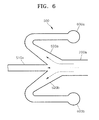
- FIG. 6 illustrates an embodiment of a structure of a second separation unit of a target particles-separating device, according to the present disclosure
- FIG. 7 is an equivalent electrical circuit diagram for describing a fluid flow in the target particles-separating device in FIG. 3 ;
- FIGS. 8 to 12 illustrate the results of observing flows of different sample solutions in the target particles-separating device in FIG. 3 .
- first, second, third, etc. may be used herein to describe various elements, components, regions, layers and/or sections, these elements, components, regions, layers and/or sections should not be limited by these terms. These terms are only used to distinguish one element, component, region, layer or section from another region, layer or section. Thus, a first element, component, region, layer or section discussed below could be termed a second element, component, region, layer or section without departing from the teachings of the invention.
- FIG. 1A illustrates an embodiment of focusing of target particles by force exerted in a multi-orifice segment including an alternating series of contraction channels and expansion chambers interconnected in a lengthwise direction, where the dimensions of the contraction channels and the expansion chambers are defined based on the size of the target particles.
- FIGS. 1 B-1 and 1 B-2 illustrate a schematic structure of an embodiment of a multi-orifice flow fractionation ("MOFF") channel, according to the present disclosure.
- FIG. 1C illustrates the results of an embodiment of separating particles of various sizes by using a single MOFF channel according to the present disclosure.
- MOFF multi-orifice flow fractionation
- the dimensionless number refers to a Reynolds number (Re) defined as a ratio of viscous force and inertial force.
- the behavior of particles of a fluid is influenced by inertial and viscous forces driven by contact with the fluid.
- the Reynolds number (Re) is determined by an average flow rate, a characteristic length, a kinematic viscosity, a dynamic viscosity, a viscous coefficient, and a density of the fluid that may affect the inertial and viscous forces.
- the Reynolds number (Re) may be of use for predicting whether a particular fluid is in a laminar flow or a turbulent flow.
- Laminar flow refers to a streamline flow of fluid in layers, while turbulent flow refers to an irregular motion of fluid leading to mixing.
- Laminar flow is a viscous force-dominant flow having a low Reynolds number (Re) in calm and constant motion of a fluid.
- Turbulent flow is an inertia force-dominant flow having a high Reynolds number (Re) in random fluctuation of a flow.
- Fluidic motions are mostly in turbulent flow, but may lead to a laminar flow when a high viscous fluid slowly passes along a narrow channel, for example, as when a blood sample passes a channel in a microfluidic device.
- the particles are focused on opposite side walls of the channel toward an outlet (see FIG. 1A , denoted by “Lateral focus”).
- the behavior of particles varies depending on a relative dimensional ratio of particles to a cross-section of the channel, which indicates that the particles in the fluid may be separated by size using the multi-orifice segment.
- FIGS. 1 B-1 and 1 B-2 are a schematic and enlarged view of an embodiment of a MOFF channel according to present disclosure using the multi-orifice segment of FIG. 1A.
- FIG. 1 B-2 illustrates portion A of FIG. 1 B-1 denoted by the dotted line outline.
- the MOFF channel is an example of a microfluidic device for continuously separating particles in fluid by size.
- the MOFF channel may include the multi-orifice segment including an alternating series of contraction channels and expansion chambers interconnected in a lengthwise direction, where the dimensions of the contraction channels and the expansion chambers are defined based on the size of target particles.
- the length and cross-section of the contraction channels and expansion chambers may vary depending on the size of target particles in fluid.
- the number of contraction channels and expansion chambers may vary. Opposite ends of the multi-orifice segment may be interconnected respectively to an inlet (see FIG. 1B-1 , denoted by "INLET”) through which a fluid sample is introduced, such as by injection, and an outlet (see FIG. 1 B-1 , denoted by “OUTLET”) through which particles in the fluid sample that are separated by size are discharged.
- a filter (see FIG. 1B-1 , denoted by "FILTER”) may be disposed between the inlet of the MOFF channel and the multi-orifice segment. The filter may filter out impurities in the fluid sample.
- the outlet of the MOFF channel may have a structure that is long in a direction in which the fluid sample flows, relative to the contraction channels and expansion chambers of the multi-orifice segment.
- the outlet of the MOFF channel may include a detection line (see FIG. 1B-2 , denoted by "DETECTION LINE") for identifying whether the particles are separated by size.
- FIG. 1 B-2 Particular figures and units in FIG. 1 B-2 are only for illustrative purposes and not to limit the dimensions and cross-sectional areas of the MOFF channel. In FIG. 1 B-2 , dimensions range from several micrometers ( ⁇ m) to several millimeters (mm).
- FIG. 1C illustrates experimental results of an embodiment of separating target particles in a fluid sample with the single MOFF channel of FIGS. 1 B-1 and 1 B-2 , in which the fluid sample was blood and the target particles were MCF-7 cells (human breast adenocarcinoma cells) present in the blood.
- the MCF-7 cells are circulating tumor cells ("CTCs") present in blood.
- CTCs circulating tumor cells
- Separating MCF-7 cells from white and red blood cells in blood is a technology applied for cancer diagnosis.
- whether metastatic cancer cells remain or not after a surgical treatment on the cancer is an influential factor to the mortality rate of the patient.
- accurately detecting even a CTC present among about 10 9 red blood cells completely is very crucial to improve the survival rate before and after a treatment to a cancer patient.
- particles in the fluid sample may be separated by size in a range of Reynolds numbers (Re).
- Reynolds numbers (Re) range from about 60 to about 90
- relatively large particles for example, about 15 ⁇ m or greater
- relatively small particles for example, about 7 ⁇ m or less
- FIG. 1C denoted by "Outside”
- FIGS. 1 B-1 and 1 B-2 illustrates the results of an embodiment of separating red blood cells (having a diameter of about 5 ⁇ m), white blood cells (having a diameter of about 10 ⁇ m), and MCF-7 cells (having a diameter of about 20 ⁇ m) with the MOFF channel of FIGS. 1 B-1 and 1 B-2 at various Reynolds numbers (Re) of about 30, 50, 90, and 100, which are selected based on the sizes of target particles and channels.
- Re Reynolds numbers
- the numbers of cells near the center and sidewall regions of the MOFF channel are different according to the Reynolds numbers (Re).
- Re the Reynolds number of 90
- the recovery of the MCF-7 cells is very as high at about 88% in the center region ("Inside") of the MOFF channel, compared to in the sidewall regions ("Outside"), while the recoveries of the red blood cells (“RBC”) and the white blood cells (“WBC”) are rather very as small at about 15.9% and 18.9%, respectively, in the center region of the MOFF channel, compared to in the sidewall regions. Therefore, by separating the particles distributed in the center region of the MOFF channel, about 88% of CTCs present in blood may be isolated.
- target particles may be separated with a high yield with the MOFF channel having an optimal Reynolds number (Re) that suits to a size of the target particles
- Re optimal Reynolds number
- Re optimal Reynolds number
- this recovery has a limitation to be applied to cancer diagnosis and treatment.
- a device and method of separating target particles with a plurality of MOFF channels have been proposed.
- FIG. 2 illustrates an embodiment of a method of separating target particles in a fluid sample with a plurality of MOFF channels, according to the present disclosure.
- the method may include: providing a plurality of MOFF channels, each including a multi-orifice segment with an inlet and outlet at opposite ends, the multi-orifice segment including an alternating series of contraction channels and expansion chambers interconnected in a lengthwise direction, where the dimensions of the contraction channels and expansion chambers are defined based on the size of the target particles; introducing a first fluid sample including target particles into an inlet of a first MOFF channel of the plurality of MOFF channels; collecting target particles discharged from a center region of an outlet of the first MOFF channel (First separation step, denoted by "I”); introducing a second fluid sample discharged from sidewall regions of the outlet of the first MOFF channel into an inlet of a second MOFF channel of the plurality of MOFF channels; and collecting target particles discharged from a center region of an outlet of the second MOFF channel (Second separation step, denoted as "ll").
- MOFF channels 100 and 200 each including a multi-orifice segment with an inlet and outlet at opposite ends, the multi-orifice segment including an alternating series of contraction channels and expansion chambers interconnected in a lengthwise direction, where the dimensions of the contraction channels and expansion chambers are defined based on the size of the target particles
- MOFF channels 100 and 200 each having a constant optimal Reynolds number (Re) according to a known size of target particles 1 and a flow quantity of a first fluid sample 5a may be manufactured.
- the MOFF channels 100 and 200 having a constant optimal Reynolds number (Re) may have an increased recovery of the target particles.
- the MOFF channels 100 and 200 may be implemented to have the same structure and length. ⁇ 0 ⁇
- the first fluid sample 5a may be injected into the inlet of the first MOFF channel 100 by using a syringe (not shown) or pump (not shown).
- the first fluid sample 5a includes remnants 2 of the target particles 1.
- the remnants 2 may have various sizes. In the embodiment of FIG. 2 , the remnant 2 may have at least a smaller size than a target particle 1.
- the first fluid sample 5a may be blood, the target particles 1 may be MCF-7 cells, and the remnants 2 may be red blood cells and/or white blood cells.
- the target particles 1 cluster in the center region of an outlet of the first MOFF channel 100, and are then collected, thus being primarily separated from the first fluid sample 5a.
- the target particles 1 may be separated with a maximum recovery by using only one MOFF channel, namely the first MOFF channel 100.
- the first separation step I about 88% of the MCF-7 cells present in blood may be separated, while about 12% of the MCF-7 cells remain not separated.
- the non-separated 12% of MCF-7 cells is expected to concentrate in the sidewall regions of the outlet of the first MOFF channel 10, which are collected along with the remnant 2 in the second separation step II, which will be described in detail below.
- the second fluid sample 5b may include the remaining target particles 1 not separated in the first fluid sample 5a in the first separation step I, and the remnants 2.
- the second fluid sample 5b may have a smaller flow quantity than the first fluid sample 5a because the second fluid sample 5b is a product of the primary separation of the target particles 1 from the first fluid sample 5a.
- the MOFF channels 100 and 200 are manufactured to have an optimal constant Reynolds number (Re) in consideration of a flow quantity of the first fluid sample 5a.
- a flow quantity into another MOFF channel namely, the second MOFF channel 200
- the introducing of the second fluid sample 5b into the inlet of the second MOFF channel 200 may further include introducing a buffer 25 into the inlet of the second MOFF channel 200 so that a quantity of the fluid introduced into the inlet of the second MOFF channel 200, including the second fluid sample 5b and the buffer 25, is equal to the quantity of the first fluid sample 5a introduced into the inlet of the first MOFF channel 100.
- the second fluid sample 5b and the buffer 25 may be introduced together into the inlet of the second MOFF channel 200.
- the introducing of the second fluid sample 5b discharged from the sidewall regions of the outlet of the first MOFF channel 100 into the inlet of the second MOFF channel 200 may further include introducing the buffer 25 into the inlet of the second MOFF channel 200 so that a quantity of the fluid introduced into the inlet of the second MOFF channel 20, including the second fluid sample 5b and the buffer 25, is different from the quantity of the first fluid sample 5a introduced into the inlet of the first MOFF channel 100.
- the quantity of the buffer 25 may be adjusted to separate particles of different sizes in the first fluid sample 5a.
- the first MOFF channel 100 and the second MOFF channel 200 may have different flow quantities, and thus different Reynolds numbers (Re).
- Re Reynolds numbers
- the sizes of particles discharged from the center region and/or the sidewall regions of the first MOFF channel 100 are different from those of the second MOFF channel 200 so that particles of different sizes in the first fluid sample 5a may be separated passing through the first MOFF channel 100 and the second MOFF channel 200.
- the target particles 1 In the second separation step II of collecting the target particles 1 discharged from the center region of an outlet of the second MOFF channel 200, the target particles 1 cluster in the center region of the outlet of the second MOFF channel 200, and are collected, thus being secondarily separated from the second fluid sample 5b.
- the target particles 1 may be separated with a maximum recovery by using one MOFF channel, namely, the second MOFF channel 200, as first MOFF channel 100.
- the remnants 2 and the remaining target particles 1, not separated in the second separation step II, cluster in the sidewall regions of the outlet of another MOFF channel, and are separated in a third separation step III (not shown).
- the MCF-7 cells present in blood may be separated in the first separation step I, and about 12% of the MCF-7 cells remaining not separated in the first separation step I may be separated with a yield of about 88% in the second separation step II.
- about 98.56% (88% + 12% X 0.88) of the MCF-7 cells may be separated from the initial blood sample.
- successive separation steps, including a third separation step are performed, the target particles may be separated with a yield of nearly 100%.
- FIG. 3 illustrates an embodiment of a device for separating target particles in a fluid sample with a plurality of MOFF channels, according to the present disclosure.
- the target particles-separating device may include at least three MOFF channels, namely, first, second, and third MOFF channels 100, 200a, and 200b, each including a multi-orifice segment with an inlet and outlet at opposite ends, the multi-orifice segment including an alternating series of contraction channels and expansion chambers interconnected in a lengthwise direction, where the dimensions of the contraction channels and expansion chambers are defined based on the size of target particles; and a first separation unit 400 including a first separation channel 410 and first branch channels 420a and 420b, the first separation channel 410 interconnected in fluid communication with a center region of an outlet of the first MOFF channel 100, the first branch channels 420a and 420b interconnected in fluid communication with the sidewall regions of the outlet of the first MOFF channel 100 and respectively with the inlets of the second and third MOFF channels 200a and 200b.
- MOFF channels namely, first, second, and third MOFF channels 100, 200a, and 200b
- the target particles-separating device may include buffer inlets 20a and 20b in at least a region of the inlets of the respective second and third MOFF channels 200a and 200b to allow a buffer flow into the second and third MOFF channels 200a and 200b.
- a detailed description of the first, second, and third MOFF channels 100, 200a, and 200b is provided above with reference to FIG. 1 . As described with reference to FIG.
- the first, second, and third MOFF channels 100, 200a, and 200b may each include a multi-orifice segment including an alternating series of contraction channels and expansion chambers interconnected in a lengthwise direction, where the dimensions of the contraction channels and expansion chambers are defined based on the size of target particles, and may be designed to have an optimal constant Reynolds number (Re) according to a size of target particles and a flow quantity of a fluid sample.
- Re Reynolds number
- the outlet of the first MOFF channel 100 may be interconnected in fluid communication with the inlets of the second and third MOFF channels 200a and 200b. The target particles in the fluid sample may be repeatedly separated using each of the separate single first, second, and third MOFF channels 100, 200a, and 200b.
- the target particles-separating device may further include the first separation unit 400 including the first separation channel 410 that is interconnected in fluid communication with the center region of the outlet of the first MOFF channel 100.
- the first separation unit 400 may further include the first branch channels 420a and 420b interconnecting the sidewall regions of the outlet of the first MOFF channel 100 in fluid communication with the inlets of the second and third MOFF channels 200a and 200b, respectively.
- first MOFF channel 100 As the fluid sample is introduced into the first MOFF channel 100, while passing through the first MOFF channel 100, relatively small target particles present in the fluid sample are concentrated on the sidewall regions of the outlet of the first MOFF channel 100, and are driven by fluid pressure to travel further along the first branch channels 420a and 420b interconnected in fluid communication with the sidewall regions of the outlet of the first MOFF channel 100. In this case, some remaining target particles, not having flowed into the first separation channel 410, may flow into the first branch channels 420a and 420b. Referring to FIG.
- the first branch channels 420a and 420b respectively connect one of the sidewall regions of the outlet of the first MOFF channel 100 in fluid communication with the inlet of the second MOFF channel 200a, and the other sidewall region of the outlet of the first MOFF channel 100 in fluid communication with the inlet of the third MOFF channel 200b.
- the target particles may be primarily separated.
- the flow quantity of the fluid sample entering the second MOFF channel 200a and the third MOFF channel 200b may be reduced due to a reduced fluid pressure by friction in the first MOFF channel 100 and a branch structure of the first separation unit 400, including the first separation channel 410 and the first branch channels 420a and 420b, and a change in fluid flow such as a back flow caused from a fluidic resistance change may occur.
- a change in fluid flow such as a back flow caused from a fluidic resistance change may occur.
- the inlets of the second and third MOFF channels 200a and 200b may be connected in fluid communication with the buffer inlets 20a and 20b for guiding a buffer to flow into the second and third MOFF channels 200a and 200b.
- a buffer may be supplied from the buffer inlets 20a and 20b to adjust the flow quantity and flow rate of the fluid sample in the second and third MOFF channels 220a and 220b to be consistent with those of the fluid sample entering the first MOFF channel 100.
- a flow quantity Q D1 of the fluid sample in the first branch channel 420a is less than a flow quantity Q 1 ( FIG. 4 ) of the fluid sample in the first MOFF channel 100.
- a change in flow rate may occur while the fluid sample passes through the first separation unit 400.
- the reduced flow rate and flow quantity Q D1 of the fluid sample in the first branch channel 420a may be compensated for so that the flow rate and flow quantity Q 2 in the second MOFF channel 200a are maintained consistent with the flow rate and flow quantity Q 1 of the fluid sample in the first MOFF channel 100.
- a buffer may be supplied from the buffer inlets 20a and 20b to adjust the flow quantity and flow rate of the fluid sample in the second and third MOFF channels 220a and 220b to be different from those of the fluid sample entering the first MOFF channel 100.
- a flow quantity Q D1 of the fluid sample in the first branch channel 420a is less than a flow quantity Q 1 ( FIG. 4 ) of the fluid sample in the first MOFF channel 100.
- a change in flow rate may occur while the fluid sample passes the first separation unit 400.
- the reduced flow rate and flow quantity Q D1 of the fluid sample in the first branch channel 420a may be compensated for so that the flow rate and flow quantity Q 2 in the second MOFF channel 200a is different from the flow rate and flow quantity Q 1 of the fluid sample in the first MOFF channel 100.
- dimensions of the first separation channel 410 may be determined such that the first separation channel 410 has a relatively large fluidic resistance compared to a fluidic resistance determined by the dimensions of the first branch channels 420a and 420b.
- a cross-sectional area of the first separation channel 410 may be relatively small compared to that of the first branch channels 420a and 420b.
- a cross-sectional area and a fluidic resistance of each of the first branch channels 420a and 420b may be defined based on the cross-sectional area and fluidic resistance of the first separation channel 410, so as to suppress a change in fluid flow such as a back flow into the first separation unit 400 and have a stable inflow of the fluid sample into the second and third MOFF channels 200a and 200b.
- a change in fluid flow such as a back flow into the first separation unit 400 and have a stable inflow of the fluid sample into the second and third MOFF channels 200a and 200b.
- the flow quantity Q 1 of the fluid sample in the first MOFF channel 100 may be defined as a sum of individual laminar flows of target particles in the fluid sample with particular sizes, for example, a sum of a laminar flow Q c in the center region of the outlet of the first MOFF channel 100, and laminar flows Q a and Q b in the sidewall regions of the outlet of the first MOFF channel 100.
- the laminar flow Q c in the center region may flow into the first separation channel 410, and the laminar flows Q a and Q b in the sidewall regions may flow into the first branch channels 420a and 420b, respectively.
- the branched channel structure causes changes in fluidic resistance of each laminar flow.
- the cross-sectional areas d a and d b respectively of the first branch channels 420a and 420b are adjusted to be larger than a cross-sectional area d c of the first separation channel 410 to obtain a relatively low fluidic resistance in the first branch channels 420a and 420b, compared to the fluidic resistance of the first separation channel 410, a change in fluid flow, such as a back flow, in the first separation unit 400 may be reduced, thereby having a stable inflow of the fluid sample into the second MOFF channel 200a and the third MOFF channel 200b.
- the inlet of the first MOFF channel 100 may be connected in fluid communication with a sample inlet 10 for introducing the fluid sample to the target particles-separating device.
- the outlets of the first separation channel 400, and second separation channels 510a and 510b may be connected in fluid communication with one target particle outlet 30 via which the target particles in the fluid sample are collected.
- FIG. 6 illustrates an embodiment of a portion of a structure of a second separation unit 500 of the target particles-separating device, according to the present disclosure.
- the target particles-separating device may include the second separation unit 500 including the second separation channels 510a and 510b, and second branch channels 520a, 520b, 520c and 520d, where the second separation channels 510a and 510b are interconnected in fluid communication with a center region of the outlet of the second and third MOFF channels 200a and 200b, respectively, the second branch channels 520a, 520b, 520c and 520d interconnected in fluid communication with sidewall regions of the outlet of the second and third MOFF channels 200a and 200b, respectively.
- the second branch channels 520a and 520b may be connected in fluid communication with waste chambers 600a and 600b for collecting the remnants, excluding the target particles, in the fluid sample, respectively.
- the non-separated particles in the fluid sample remaining not separated to flow into the second separation channel 510a of the second separation unit 500, may be stored in the waste chambers 600a and 600b, or may be discharged out of the target particles-separating device.
- target particles may be separated similarly as when the fluid sample is introduced into the second MOFF channel 200a from the first separation unit 400.
- FIG. 7 is an equivalent electrical circuit diagram for describing fluid flow in the target particles-separating device in FIG. 3 .
- FIG. 7 is an equivalent electrical circuit of the target particles-separating device of FIG. 3 . To manufacture the target particles-separating device of FIG. 3 , the following conditions are necessary.
- fluid resistors R 1 may indicate fluidic resistance in the first, second, and third MOFF channels 100, 200a, and 200b
- a fluid resistor R c may indicate fluidic resistances in the first separation channel 410
- Q s may indicate a flow quantity of the buffer supplied from the buffer inlet
- a fluid resistor R s may indicate fluidic resistance in the second separation unit 500
- Q R1 indicates a flow quantity and flow rate the fluid sample entering the first MOFF channel 100.
- Q R1 is assumed to be 150 microliters per minute( ⁇ l/min).
- a flow quantity across the fluid resistors R 1 of the first, second, and third MOFF channels 100, 200a, and 200b may be consistent, for example, as 150 ⁇ l/min with the assumption that a Reynolds number (Re) is 90.
- a flow quantity Q Rc across the fluid resistor R c of the first separation channel 410 may be about 20% of the flow quantity Q R1 across the fluid resistors R 1 of the first, second, and third MOFF channels 100, 200a, and 200b.
- a fluidic resistance of the fluid resistor R s of the second separation unit 500 may be negligibly small relative to that of the fluid resistor R 1 of the first, second, or third MOFF channels 100, 200a, and 200b (Rs ⁇ R 1 ).
- the fluidic resistance of the fluid resistor R c may be given, the fluidic resistances of the fluid resistors R 1 may be calculated, and a cross-sectional area of the first branch channels 420a and 420b may be determined.
- the fluidic resistance of a rectangular cross-section channel may be determined using a known equation. For example, whether a flow is laminar or turbulent may be determined by Equation 3 below, a resistance of laminar flow in the channel may be determined by Equation 4 below, a hydraulic diameter of a non-circular, rectangular channel may be determined by Equation 5 below, and a shape compensation coefficient of a non-circular, rectangular channel may be determined by Equation 6.
- Equation 3-6 Parameters in Equations 3-6 are defined as follows: p: fluid density of water in kilograms per cubed meter (kg/m 3 ), V: average fluid velocity in meters per second (m/s), p: dynamic viscosity in Newton second per square meters (N ⁇ s/m 2 ), D h : hydraulic diameter in meters (m), A: area of the channel cross section (m 2 ), and fRe: shape constant.
- the particles-separating device of FIG. 3 was fabricated by soft-lithography techniques.
- a 6-inch silicon wafer was used as a substrate, and SU-8 (SU-8 2050, available from MicroChem Corporation, Massachusetts, United States) was used for a channel master mold.
- a pattern of the particles-separating device was replicated with polydimethylsiloxane (“PDMS”) (SYLGARD ® 184, available from Dow Corning Corporation, Michigan, United States).
- PDMS polydimethylsiloxane
- a volumetric mixture of PDMS and a curing agent at a ratio of about 10:1 was poured on the channel master mold, and followed by degassing the mixture and placing the wafer on a hot plate at about 75 degrees Celsius (°C) for about 60 minutes.
- a cured polymer mixture was removed from the channel master mold and was punched to form an inlet and an outlet, and bonded to a glass after plasma treatment using a plasma generator (Cute-B Plasma system, available from FEMTO Science, Korea), thereby manufacturing the particles-separating device.
- a plasma generator Cute-B Plasma system, available from FEMTO Science, Korea
- the first, second, and third MOFF channels 100, 200a and 200b of the particles-separating device each include an inlet, a filter, a multi-orifice segment, and an outlet.
- the multi-orifice segment includes an alternating series of eighty (80) contraction channels and eighty (80) expansion chambers, each contraction channel having a width of about 40 ⁇ m and a length of about 100 ⁇ m, each expansion chamber having a width of about 200 ⁇ m and a length of about 200 ⁇ m, and both having a thickness of about 40 ⁇ m .
- the first separation channel 410 of the first separation unit 400 may have a width of about 40 ⁇ m and a length of about 40 mm, and the first branch channels 420a and 420b may each have a width of about 1 mm and a length of about 10 mm.
- sample solution was prepared in a 0.5 wt% TWEEN ® 20 (available from Sigma-Aldrich Co., Missouri, United States) aqueous solution.
- sample solution 1 including fluorescent polystyrene microspheres having a diameter of about 15 ⁇ m (available from Thermo Fisher Scientific Inc., Mfr. No. 36-4, red, 542/612 nm)
- sample solution 2 including fluorescent polystyrene microspheres having a diameter of about 7 ⁇ m (available from Thermo Fisher Scientific Inc., Mfr. No.
- sample solution 4 including 1,000 MCF-7 cells/ ⁇ l
- sample solution 5 which is a mixture of the sample solution 4 and 50,000 RBCs/ ⁇ l.
- I-70 available from Olympus, Japan
- CCD camera ProgRes C10, available
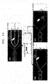
- FIG. 8 illustrates flows of the sample solutions 1 and 2 in the second and third MOFF channels 200a and 200b of the particles-separating device.
- Particles distributions in the sample solutions 1 and 2 at the 1 st (upstream), 40 th (midstream), and 80 th (downstream) orifices of the second and third MOFF channels 200a and 200b were fluorescently captured.
- particle separation began to occur around the 35 th to 45 th orifices, and stable particle distribution was observed at around the 70 th to 80 th orifices.
- About 7 ⁇ m particles in the sample solution 2 were observed to cluster near both sidewall regions in the first MOFF channel 100, but to only one sidewall region in the second and third MOFF channels 200a and 200b.
- the 7 ⁇ m particles tend to only flow near one sidewall region, and are biased to one sidewall region as the buffer flows in from the buffer inlet.
- the biased particles are found to be continuously biased to the same sidewall region until the end of the multi-orifice segment.
- FIG. 9 illustrates flows of the sample solutions 1 and 2 in the first and second separation unit 500 of the target particles-separating device.
- relatively large particles (15 ⁇ m, red) are found to cluster around the center region of the first separation unit 400 of the target particles-separating device, while relatively small particles (7 ⁇ m, green) tend to cluster near the sidewall regions of the first separation unit 400.
- relatively large particles (15 ⁇ m, red) are found to cluster around the center region of the second separation unit 500 of the target particles-separating device, while relatively small particles (7 ⁇ m, green) tend to cluster near the sidewall regions of the second separation unit 500.
- each MOFF channel 100, 200a and 200b about 140 ⁇ m inwards from the sidewall region of the 800 ⁇ m-wide outlet
- the particles in the sample solution flow from the first MOFF channel 100 into the second and third MOFF channels 200a and 200b, thereby branching off from the first MOFF channel 100, and are diluted with a supply of a buffer, thus showing a reduced fluorescence in the second and third MOFF channels compared to that in the first MOFF channel.
- FIG. 10 illustrates flows of the sample solution 3 in the first and second separation units 400 and 500 of the target particles-separating device.
- Fluorescent images of FIG. 10 were acquired using a green fluorescent filter cube (U-MWB2, available from Olympus, Japan) so that red images may look yellow when two red and green colors are presented at the same time.
- U-MWB2 green fluorescent filter cube
- FIG. 11 illustrates flows of the sample solution 4 in the first MOFF channel 100, the first separation unit 400, and the second separation unit 500 of the target particles-separating device.
- the MCF-7 cells are found to cluster near the center region of the first MOFF channel 100, beginning from the 35 th to 45 th orifice regions of the first MOFF channel 100.
- MCF-7 cells are found to cluster near the center region of the first separation unit 100.
- a right-side 2 nd stage bottom view of FIG. 11 shows that MCF-7 cells also cluster near the center region of the second separation unit 500.
- FIG. 12 illustrates flows of the sample solution 5 in the first and second MOFF channels 100, 200a and 200b of the target particles-separating device.
- the MCF-7 cells are found to cluster near the center region of the first separation unit 400, while RBCs, smaller than the MCF-7 cells, cluster near the sidewall regions of the first separation unit 400.
- RBCs, smaller than the MCF-7 cells cluster near the sidewall regions of the second separation unit 500.
- target particles in a fluid sample may be efficiently separated.
Applications Claiming Priority (2)
| Application Number | Priority Date | Filing Date | Title |
|---|---|---|---|
| KR20100055112 | 2010-06-10 | ||
| KR1020110037353A KR101844413B1 (ko) | 2010-06-10 | 2011-04-21 | Moff 채널을 이용한 표적 입자 분리 장치 및 분리 방법 |
Publications (1)
| Publication Number | Publication Date |
|---|---|
| EP2404674A1 true EP2404674A1 (de) | 2012-01-11 |
Family
ID=44801956
Family Applications (1)
| Application Number | Title | Priority Date | Filing Date |
|---|---|---|---|
| EP11169461A Withdrawn EP2404674A1 (de) | 2010-06-10 | 2011-06-10 | Partikeltrennende Target-Vorrichtung und Verfahren unter Verwendung eines Flussfraktionierungskanals mit mehreren Öffnungen |
Country Status (2)
| Country | Link |
|---|---|
| US (1) | US8590710B2 (de) |
| EP (1) | EP2404674A1 (de) |
Cited By (1)
| Publication number | Priority date | Publication date | Assignee | Title |
|---|---|---|---|---|
| US11130130B2 (en) | 2017-02-06 | 2021-09-28 | University Of Leeds | Fluid flow device |
Families Citing this family (10)
| Publication number | Priority date | Publication date | Assignee | Title |
|---|---|---|---|---|
| US8590710B2 (en) * | 2010-06-10 | 2013-11-26 | Samsung Electronics Co., Ltd. | Target particles-separating device and method using multi-orifice flow fractionation channel |
| CA2850335A1 (en) * | 2011-09-30 | 2013-06-20 | The Regents Of The University Of California | Devices and methods for shape-based particle separation |
| JP6326582B2 (ja) * | 2012-10-15 | 2018-05-23 | 国立大学法人名古屋大学 | 微粒子分離用マイクロ流路チップ、該チップを用いた微粒子分離用システム及び微粒子分離方法 |
| KR101647551B1 (ko) * | 2014-06-23 | 2016-08-23 | 경희대학교 산학협력단 | 미세입자 분리 장치 및 이를 이용한 분리 방법 |
| CN105319308B (zh) * | 2014-07-07 | 2017-05-17 | 北京北分天普仪器技术有限公司 | 白酒各类组成的气相色谱/质谱分析装置和分析方法 |
| US20170113222A1 (en) * | 2015-10-22 | 2017-04-27 | Owl biomedical, Inc. | Particle manipulation system with spiral focusing channel |
| US20170191982A1 (en) * | 2016-01-06 | 2017-07-06 | Massachusetts Institute Of Technology | Constriction-Expansion Blood Plasma Separation |
| WO2017181186A1 (en) * | 2016-04-15 | 2017-10-19 | Vortex Biosciences, Inc. | Microfluidic chips and cartridges and systems utilizing microfluidic chips and cartridges |
| EP3860759A1 (de) * | 2018-10-03 | 2021-08-11 | Verily Life Sciences LLC | Systeme und verfahren zur aufrechterhaltung konstanter volumetrischer strömungsraten in einem fluidkanal |
| US11285484B2 (en) * | 2019-08-12 | 2022-03-29 | Intabio, Llc | Multichannel isoelectric focusing devices and high voltage power supplies |
Citations (5)
| Publication number | Priority date | Publication date | Assignee | Title |
|---|---|---|---|---|
| US20070026381A1 (en) * | 2005-04-05 | 2007-02-01 | Huang Lotien R | Devices and methods for enrichment and alteration of cells and other particles |
| US20080318324A1 (en) * | 2007-06-20 | 2008-12-25 | University Of Washington | Biochip for High-Throughput Screening of Circulating Tumor Cells |
| WO2009115575A1 (en) * | 2008-03-19 | 2009-09-24 | Oncnosis Pharma Aie | Method and apparatus for separating particles in a fluid |
| US20090283456A1 (en) * | 2008-05-13 | 2009-11-19 | Commissariat A L'energie Atomique | Method of sorting particles or particle clusters in a fluid flowing in a channel |
| US20090283474A1 (en) * | 2008-05-13 | 2009-11-19 | Commissariat A L'energie Atomique | Device and a method for separating a suspension |
Family Cites Families (8)
| Publication number | Priority date | Publication date | Assignee | Title |
|---|---|---|---|---|
| US5489506A (en) * | 1992-10-26 | 1996-02-06 | Biolife Systems, Inc. | Dielectrophoretic cell stream sorter |
| KR100552620B1 (ko) | 2004-01-13 | 2006-02-20 | 플래닛팔이 주식회사 | 적혈구 지수 측정 장치 및 방법 |
| US7993821B2 (en) | 2005-08-11 | 2011-08-09 | University Of Washington | Methods and apparatus for the isolation and enrichment of circulating tumor cells |
| KR100843339B1 (ko) | 2006-12-07 | 2008-07-03 | 한국전자통신연구원 | 혈액 중의 혈장 분리를 위하여 마이크로채널을 이용한혈장분리기 및 이에 의한 혈장분리방법 |
| EP2479552B1 (de) * | 2007-04-02 | 2015-09-02 | Acoustic Cytometry Systems, Inc. | Verfahren zur verbesserten Analyse von in einem akustischen Feld fokussierten Zellen und Partikeln |
| WO2008130618A1 (en) * | 2007-04-19 | 2008-10-30 | The Charles Stark Draper Laboratory, Inc. | Method and apparatus for separating particles, cells, molecules and particulates |
| WO2009140326A2 (en) | 2008-05-16 | 2009-11-19 | Board Of Supervisors Of Louisiana State University And Agricultural And Mechanical College | Microfluidic isolation of tumor cells or other rare cells from whole blood or other liquids |
| US8590710B2 (en) * | 2010-06-10 | 2013-11-26 | Samsung Electronics Co., Ltd. | Target particles-separating device and method using multi-orifice flow fractionation channel |
-
2011
- 2011-06-09 US US13/156,630 patent/US8590710B2/en not_active Expired - Fee Related
- 2011-06-10 EP EP11169461A patent/EP2404674A1/de not_active Withdrawn
Patent Citations (5)
| Publication number | Priority date | Publication date | Assignee | Title |
|---|---|---|---|---|
| US20070026381A1 (en) * | 2005-04-05 | 2007-02-01 | Huang Lotien R | Devices and methods for enrichment and alteration of cells and other particles |
| US20080318324A1 (en) * | 2007-06-20 | 2008-12-25 | University Of Washington | Biochip for High-Throughput Screening of Circulating Tumor Cells |
| WO2009115575A1 (en) * | 2008-03-19 | 2009-09-24 | Oncnosis Pharma Aie | Method and apparatus for separating particles in a fluid |
| US20090283456A1 (en) * | 2008-05-13 | 2009-11-19 | Commissariat A L'energie Atomique | Method of sorting particles or particle clusters in a fluid flowing in a channel |
| US20090283474A1 (en) * | 2008-05-13 | 2009-11-19 | Commissariat A L'energie Atomique | Device and a method for separating a suspension |
Non-Patent Citations (3)
| Title |
|---|
| JAE-SUNG PARK ET AL: "Continuous focusing of microparticles using inertial lift force and vorticity via multi-orifice microfluidic channels", LAB ON A CHIP, ROYAL SOCIETY OF CHEMISTRY, CAMBRIDGE, GB, vol. 9, no. 7, 7 April 2009 (2009-04-07), pages 939 - 948, XP007907810, ISSN: 1473-0197, DOI: 10.1039/B813952K * |
| PARK J-S; JUNG H-I: "Multiorifice flow fractionation: Continuous size-based separation of microspheres using a series of contraction/expansion microchannels", ANALYTICAL CHEMISTRY, vol. 81, no. 20, 15 October 2009 (2009-10-15), pages 8280 - 8288, XP002662652, ISSN: 0003-2700 * |
| TAE SEOK SIM ET AL: "Multistage-multiorifice flow fractionation (MS-MOFF): continuous sizebased separation of microspheres using multiple series of contraction/ expansion microchannels", LAB ON A CHIP, ROYAL SOCIETY OF CHEMISTRY, CAMBRIDGE, GB, vol. 11, no. 1, 7 January 2011 (2011-01-07), pages 93 - 99, XP007917464, ISSN: 1473-0197, DOI: 10.1039/C0LC00109K * |
Cited By (1)
| Publication number | Priority date | Publication date | Assignee | Title |
|---|---|---|---|---|
| US11130130B2 (en) | 2017-02-06 | 2021-09-28 | University Of Leeds | Fluid flow device |
Also Published As
| Publication number | Publication date |
|---|---|
| US8590710B2 (en) | 2013-11-26 |
| US20110303586A1 (en) | 2011-12-15 |
Similar Documents
| Publication | Publication Date | Title |
|---|---|---|
| US8590710B2 (en) | Target particles-separating device and method using multi-orifice flow fractionation channel | |
| US11498071B2 (en) | Systems and methods for particle focusing in microchannels | |
| Tanaka et al. | Separation of cancer cells from a red blood cell suspension using inertial force | |
| US10144009B2 (en) | Microfluidics sorter for cell detection and isolation | |
| Chiu et al. | Enhancement of microfluidic particle separation using cross-flow filters with hydrodynamic focusing | |
| JP6604945B2 (ja) | 粒子クラスタを単離するためのマイクロ流体方法およびシステム | |
| Yuan et al. | Continuous plasma extraction under viscoelastic fluid in a straight channel with asymmetrical expansion–contraction cavity arrays | |
| US11833508B2 (en) | Multi-dimensional double spiral device and methods of use thereof | |
| CN209287355U (zh) | 微流控芯片及含有该微流控芯片的装置 | |
| Choi et al. | Microfluidic high-throughput single-cell mechanotyping: Devices and applications | |
| US20150375228A1 (en) | Devices for sorting cells in a sample and methods for use thereof | |
| US10406521B2 (en) | Micro-droplet array for multiple screening of a sample | |
| KR101844413B1 (ko) | Moff 채널을 이용한 표적 입자 분리 장치 및 분리 방법 | |
| Ma et al. | Experimental and theoretical study of hydrodynamic cell lysing of cancer cells in a high-throughput Circular Multi-Channel Microfiltration device | |
| Mitra et al. | Separation of particles in spiral micro-channel using Dean’s flow fractionation | |
| US20190275522A1 (en) | Microscale cell filter | |
| JP2006226753A (ja) | 成分分離機構と成分分離方法 | |
| US20230383239A1 (en) | Microscale cell filter | |
| Chen | Flow and Interaction Patterns between Tumor Cells and Microfabricated Structures | |
| Sun | Centrifugal Microfluidics for Label-free Isolation of Leukocytes Subpopulations from Whole Blood | |
| Sathuluri et al. | Development of High-throughput Compartmental Microfluidic Devices for Multiplexed Single-cell Sorting, Manipulation and Analysis |
Legal Events
| Date | Code | Title | Description |
|---|---|---|---|
| AK | Designated contracting states |
Kind code of ref document: A1 Designated state(s): AL AT BE BG CH CY CZ DE DK EE ES FI FR GB GR HR HU IE IS IT LI LT LU LV MC MK MT NL NO PL PT RO RS SE SI SK SM TR |
|
| AX | Request for extension of the european patent |
Extension state: BA ME |
|
| PUAI | Public reference made under article 153(3) epc to a published international application that has entered the european phase |
Free format text: ORIGINAL CODE: 0009012 |
|
| 17P | Request for examination filed |
Effective date: 20120710 |
|
| RAP1 | Party data changed (applicant data changed or rights of an application transferred) |
Owner name: INDUSTRY-ACADEMIC COOPERATION FOUNDATION, YONSEI U Owner name: SAMSUNG ELECTRONICS CO., LTD. |
|
| 17Q | First examination report despatched |
Effective date: 20140903 |
|
| STAA | Information on the status of an ep patent application or granted ep patent |
Free format text: STATUS: THE APPLICATION IS DEEMED TO BE WITHDRAWN |
|
| 18D | Application deemed to be withdrawn |
Effective date: 20150114 |