EP2404535B1 - Grill handle with heat shield - Google Patents
Grill handle with heat shield Download PDFInfo
- Publication number
- EP2404535B1 EP2404535B1 EP10013304.0A EP10013304A EP2404535B1 EP 2404535 B1 EP2404535 B1 EP 2404535B1 EP 10013304 A EP10013304 A EP 10013304A EP 2404535 B1 EP2404535 B1 EP 2404535B1
- Authority
- EP
- European Patent Office
- Prior art keywords
- handle
- heat shield
- lid
- cooking chamber
- barbecue grill
- Prior art date
- Legal status (The legal status is an assumption and is not a legal conclusion. Google has not performed a legal analysis and makes no representation as to the accuracy of the status listed.)
- Active
Links
Images



Classifications
-
- A—HUMAN NECESSITIES
- A47—FURNITURE; DOMESTIC ARTICLES OR APPLIANCES; COFFEE MILLS; SPICE MILLS; SUCTION CLEANERS IN GENERAL
- A47J—KITCHEN EQUIPMENT; COFFEE MILLS; SPICE MILLS; APPARATUS FOR MAKING BEVERAGES
- A47J37/00—Baking; Roasting; Grilling; Frying
- A47J37/06—Roasters; Grills; Sandwich grills
- A47J37/07—Roasting devices for outdoor use; Barbecues
-
- A—HUMAN NECESSITIES
- A47—FURNITURE; DOMESTIC ARTICLES OR APPLIANCES; COFFEE MILLS; SPICE MILLS; SUCTION CLEANERS IN GENERAL
- A47J—KITCHEN EQUIPMENT; COFFEE MILLS; SPICE MILLS; APPARATUS FOR MAKING BEVERAGES
- A47J37/00—Baking; Roasting; Grilling; Frying
- A47J37/06—Roasters; Grills; Sandwich grills
- A47J37/07—Roasting devices for outdoor use; Barbecues
- A47J37/0786—Accessories
-
- A—HUMAN NECESSITIES
- A47—FURNITURE; DOMESTIC ARTICLES OR APPLIANCES; COFFEE MILLS; SPICE MILLS; SUCTION CLEANERS IN GENERAL
- A47J—KITCHEN EQUIPMENT; COFFEE MILLS; SPICE MILLS; APPARATUS FOR MAKING BEVERAGES
- A47J45/00—Devices for fastening or gripping kitchen utensils or crockery
- A47J45/06—Handles for hollow-ware articles
- A47J45/062—Bowl handles
-
- A—HUMAN NECESSITIES
- A47—FURNITURE; DOMESTIC ARTICLES OR APPLIANCES; COFFEE MILLS; SPICE MILLS; SUCTION CLEANERS IN GENERAL
- A47J—KITCHEN EQUIPMENT; COFFEE MILLS; SPICE MILLS; APPARATUS FOR MAKING BEVERAGES
- A47J45/00—Devices for fastening or gripping kitchen utensils or crockery
- A47J45/06—Handles for hollow-ware articles
- A47J45/08—Heat-insulating handles
- A47J45/085—Heat shields for handles
Definitions
- the embodiments described and claimed herein relate generally to barbecue grill handles. More specifically, some of the embodiments relate to heat barrier structures which reduce the temperature of, and in the region of, barbecue grill handles.
- Barbecue grills are well known in the art. Typically, these barbecue grills include a cooking chamber and a support structure.
- the cooking chamber can simply comprise an open top firebox, or a combination of a firebox and a lid. In either case, it is typical for barbecue grills to be provided with one or more handles on the cooking chamber, either for moving the barbecue grill from location to another, or for opening and closing the lid.
- both solutions are sufficient to meet the EN 1860-1:2003 standard, they both have their drawbacks. For example, both solutions result in an appearance which is less aesthetically pleasing and possibly less functional and wear-resistant. Increasing the distance between the handle and the grill can give a barbecue grill a less proportional appearance, and may cause difficulties with packaging the grill for retail sale in a compact manner. The extended handle can also impinge upon space constraints of the end user. Using wood as an alternative material is not preferable because many wood finishes quickly degrade when exposed to heat and sun, two conditions which are almost always present for barbecue grills.
- US 6298774 B1 discloses an outdoor barbecue grill including a cooking chamber with a lower portion and an upper portion removably positioned atop the lower portion.
- An automobile-shaped cover surrounds upper portion at a distance so as to form an insulative air gap therebetween.
- one or more conduits extend from the upper portion of the cooking chamber and through the cover for venting heat and smoke from said cooking chamber.
- the present invention is directed to a barbecue grill as set out in the accompanying claim 1.
- the subordinate claims 2 to 4 set out optional features.
- a barbecue grill embodying the present invention may be provided with a handle mounted exterior to a cooking chamber.
- a heat shield or a heat barrier is also provided that is positioned between a heated volume of the cooking chamber and at least a portion of the handle.
- the heat barrier comprises an externally mounted heat shield that is positioned directly between the handle and the outside surface of the cooking chamber to significantly reduce radiative and convective heat transfer to the handle.
- a barbecue grill comprising a cooking chamber defined by a lid and a firebowl; a handle affixed to an outside surface of the lid at the apex thereof; a heat shield affixed adjacent the outside surface of the lid and being disposed between the outside surface of the lid and a gripping portion of the handle,wherein the heat shield in a generally vertically aligned cross section plane has a general ly parabolic shape with two upturned ends and a vertex that has a spaced positional relationship to the outside surface of the lid, the two upturned ends being laterally spaced on opposite sides of the handle, whereby the heat shield is configured to form a heat barrier between a heated volume of the cooking chamber and the gripping portion of the handle.
- the handle extends upwardly from the outside surface of the lid.
- handle comprises a gripping portion and at least one flange portion; and, the flange portion, the lid and the heat shield each has at least one aperture which are correspondingly aligned and through which at least one fastener extends to affix the handle and the heat shield to the lid.
- the heat shield has a reflective surface to reduce radiation heat transfer.
- a barbecue grill 10 is shown in perspective view.
- the barbecue grill 10 incorporates numerous components which are common to most conventional grills.
- the grill includes a cooking chamber 20 and a cart assembly (or frame structure) 30.
- the cooking chamber includes a firebowl 22, a lid 24, an ash catcher 26, a charcoal grate 28a, and a cooking grate 28b.
- the lid 24 may be entirely removable, as shown, or could be hingedly attached to the firebowl 22.
- the bottom side of firebowl 22 and the top side of the lid 24 are generally closed, which means they are closed for all practical purposes, but may include variously located vents and grease drains.
- the cart assembly 30, as shown, includes three legs 32, two wheels 34, and a shelf 36.
- charcoal be used as a heat source
- the barbecue grill 10 can be used with various heat sources, such as electric burner elements and gas burners.
- the barbecue grill 10 as shown in Figure 1 , includes two handles 40a, 40b, one handle 40a positioned at the apex of the lid 24 and the other handle 40b positioned at a side of the firebox 22.
- both handles 40a, 40b are essentially the same in construction, and include a gripping portion 42a, 42b and a support portion 50a, 50b.
- the gripping portion 42a, 42b as shown, has a two piece, molded plastic construction (top member 44a, 44b and bottom member 46a, 46b) that are designed to connect together around support portion 50a, 50b via fastener 48a, 48b.
- top member 44a, 44b and bottom member 46a, 46b could be configured to snap together.
- Support portion 50a, 50b includes a connecting section 51a, 51b, which is disposed between the two pieces of the gripping portion 42a, 42b, and two leg portions 52a, 52b, 53a, 53b, which serve to support the gripping member 42a, 42b a spaced distance from the cooking chamber 20.
- the ends of the leg portions 52a, 52b, 53a, 53b, opposite the gripping portion 42a, 42b, include two inwardly turned flanges 55a, 55b, 56a, 56b, which are provided with apertures that align with corresponding aperatures on the cooking chamber 20.
- the handles 40a, 40b are fixed to the cooking chamber via fasteners 57a, 57b, 58a, 58b which extend through the apertures.
- the fasteners 57a, 57b, 58a, 58b comprise nut and bolt combinations.
- the handle 40a, 40b configuration shown and described is for example only, and unless otherwise indicated in the claims, are not intended to limit the scope of the claims.
- the barbecue grill 10, as shown in Figure 1 also includes two versions of a heat shield 60, 80.
- the first construction of heat shield 60 is configured for installation at an exterior of the cooking chamber, while the second construction of heat shield 80 is configured for installation at an interior of the cooking chamber.
- FIGS 2-3 two cross sectional views are provided which show the first construction of the heat shield 60 in more detail.
- the heat shield 60 is affixed adjacent the outside surface of the lid 24 and is disposed between the outside surface of the lid 24 and the gripping portion 42a of the handle.
- the heat shield 60 includes apertures which align with the apertures on the handle 40a and the lid 24, whereby the same fasteners 56a, 58a can be used to affix the heat shield 60 to the lid 24.
- the heat shield 60 has a longitudinal axis which is generally aligned with a length of the gripping portion.
- the heat shield 60 When viewed in a cross section plane normal to the longitudinal axis, the heat shield 60 has a generally parabolic shape with two upturned ends 62a, 62b and a vertex 64 that has a spaced positional relationship to the outside surface of the lid 24.
- the two upturned ends 62a, 62b are laterally spaced on opposite sides of the handle 40a, whereby the heat shield 60 is configured to form a heat barrier between a heated volume HV of the cooking chamber 20 and the gripping portion 42a of the handle. More specifically, the shape of the heat shield 60 directs heated air HA away from the handle and thereby reduces convective heat transfer from the cooking chamber 20 to the handle 40a.
- the heat shield 60 is formed from sheet metal comprising stainless steel, whereby the heat shield 60 has a reflective surface to reduce radiation heat transfer.
- FIG. 4-5 a cross sectional view and an exploded view are provided which show the second construction of the heat shield 80 in more detail.
- the heat shield 80 is affixed adjacent the inside surface of the firebowl 22, opposite the handle 40b.
- the heat shield 80 includes apertures which align with the apertures on the handle 40b and the firebowl 22, whereby the same fasteners 56b, 58b can be used to affix the heat shield 80 to the firebowl 22.
- additional nuts are provided which are placed between the shield 80 and the firebowl 22, and which act to space the heat shield 80 a distance from the inside surface of the firebowl 22.
- the heat shield 80 includes a perimetric edge region 52 and a central region 84.
- the perimetric edge region 82 of the heat shield 80 is in at least close proximity to the inside surface of the firebowl 22 and surrounds the central region of the heat shield. At least of a portion of the central region 84 of the heat shield has a spaced positional relationship to the inside surface of the firebowl 22, In this manner, the heat shield 80 defines an at least partially closed volume V, which is disposed between the heated volume HV of the cooking chamber and the handle 40b.
- the at least partially closed volume V forms an insulating barrier to insulate the handle 40b from the heated volume HV of the cooking chamber.
- air is used as the insulting material, although it is contemplated that other types of insulating material could be used, so long as they are appropriate for high temperature applications.
- the bottom edge 82a of the heat shield 80 is spaced further from the inside surface of the firebowl 22 than is the upper edge 82b of the heat shield 80. In the shown configuration, this is preferable because the heat source (i.e., charcoal) is at about the same elevation as the heat shield. Therefore, fresh, cool air F is able to enter the at least partially closed volume to better insulate the handle.
- the second embodiment of the heat shield 80 is formed from sheet metal comprising stainless steel, whereby the heat shield 80 has a reflective surface to reduce radiation heat transfer.
- first construction of the heat shield 60 is shown attached to the lid 24, and the second construction of the heat shield 80 is shown attached to the firebowl, it is contemplated that the first construction could be used on both the firebowl and lid. Moreover, it is contemplated that both constructions of the heat shield 60, 80 could be employed for use with a single handle 40a, 40b.
Landscapes
- Engineering & Computer Science (AREA)
- Food Science & Technology (AREA)
- Baking, Grill, Roasting (AREA)
Description
- The embodiments described and claimed herein relate generally to barbecue grill handles. More specifically, some of the embodiments relate to heat barrier structures which reduce the temperature of, and in the region of, barbecue grill handles.
- Barbecue grills are well known in the art. Typically, these barbecue grills include a cooking chamber and a support structure. The cooking chamber can simply comprise an open top firebox, or a combination of a firebox and a lid. In either case, it is typical for barbecue grills to be provided with one or more handles on the cooking chamber, either for moving the barbecue grill from location to another, or for opening and closing the lid.
- Over the years, as barbecue grills have grown in popularity, various standards and regulations have been enacted which specify strict safety parameters for barbecue grills. One such standard, EN 1860-1:2003, section 4.2.6, precludes the surface temperature of the handle from exceeding certain values when tested under certain conditions. In their attempts to meet this standard, barbecue grill manufacters have accepted and implemented two alternative solutions. The first is to increase the distance between the gripping portion of the handle and the cooking chamber. It is no surprise that grill manufacturers have adopted this obvious solution. Indeed, it is well known that the magnitude of radiation heat transfer between two objects is inversely proportional to the distance between the two objects; i.e., the farther the objects are away from each other, the lower the magnitude of radiation heat transfer. The same generally applies for conductive and convective heat tranfer between two objects. The second solution is to use a material specified in the standard which has a high temperature criteria, e.g. wood. This is likewise an obvious solution.
- Although the two solutions identified above are sufficient to meet the EN 1860-1:2003 standard, they both have their drawbacks. For example, both solutions result in an appearance which is less aesthetically pleasing and possibly less functional and wear-resistant. Increasing the distance between the handle and the grill can give a barbecue grill a less proportional appearance, and may cause difficulties with packaging the grill for retail sale in a compact manner. The extended handle can also impinge upon space constraints of the end user. Using wood as an alternative material is not preferable because many wood finishes quickly degrade when exposed to heat and sun, two conditions which are almost always present for barbecue grills.
-
US 6298774 B1 discloses an outdoor barbecue grill including a cooking chamber with a lower portion and an upper portion removably positioned atop the lower portion. An automobile-shaped cover surrounds upper portion at a distance so as to form an insulative air gap therebetween. At locations reminiscent of automobile tail pipes, one or more conduits extend from the upper portion of the cooking chamber and through the cover for venting heat and smoke from said cooking chamber. - The present invention is directed to a barbecue grill as set out in the accompanying claim 1. The subordinate claims 2 to 4 set out optional features.
- Several embodiments of barbecue grill with a heat barrier or shield for a barbecue grill handle are described and claimed herein. These embodiments employ various solutions for reducing the temperture of, and in the region of, a barbecue grill handle that run contrary to the accepted solutions of other individuals possessing skill in the pertinent art. The solutions dislosed herein negate the need to extend the distance between the handle and the cooking chamber of a grill, and the need to use materials with a high temperature threshold, such as wood. These solutions therefore provide the grill designer with flexibility in designing and selecting materials for barbecue grill handles.
- A barbecue grill embodying the present invention may be provided with a handle mounted exterior to a cooking chamber. A heat shield or a heat barrier is also provided that is positioned between a heated volume of the cooking chamber and at least a portion of the handle. The heat barrier comprises an externally mounted heat shield that is positioned directly between the handle and the outside surface of the cooking chamber to significantly reduce radiative and convective heat transfer to the handle.
- A barbecue grill comprising a cooking chamber defined by a lid and a firebowl; a handle affixed to an outside surface of the lid at the apex thereof; a heat shield affixed adjacent the outside surface of the lid and being disposed between the outside surface of the lid and a gripping portion of the handle,wherein the heat shield in a generally vertically aligned cross section plane has a general ly parabolic shape with two upturned ends and a vertex that has a spaced positional relationship to the outside surface of the lid, the two upturned ends being laterally spaced on opposite sides of the handle, whereby the heat shield is configured to form a heat barrier between a heated volume of the cooking chamber and the gripping portion of the handle. Preferably, the handle extends upwardly from the outside surface of the lid. Preferably handle comprises a gripping portion and at least one flange portion; and, the flange portion, the lid and the heat shield each has at least one aperture which are correspondingly aligned and through which at least one fastener extends to affix the handle and the heat shield to the lid. preferably the heat shield has a reflective surface to reduce radiation heat transfer.
- These and other features, aspects, objects, and advantages of the embodiments described and claimed herein will become better understood upon consideration of the following detailed description, appended claims, and accompanying drawings where:
-
FIG. 1 is a perspective view of a barbecue grill embodying the present invention; -
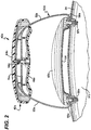
FIG. 2 is a first sectional view of a grill handle and heat shield of the barbecue grill shown inFigure 1 ; -
FIG. 3 is a second sectional view of the same; -
FIG. 4 is a first section view of a second grill handle and heat shield of the barbecue shown inFigure 1 ; and, -
FIG. 5 is an exploded view of the same. - It should be understood that the drawings are not necessarily to scale and that the embodiments are sometimes illustrated by graphic symbols, phantom lines, diagrammatic representations and fragmentary views. In certain instances, details which are not necessary for an understanding of the embodiments described and claimed herein or which render other details difficult to perceive may have been omitted.
- Like reference numerals will be used to refer to like or similar parts from figure to figure in the following detailed description of the drawings.
- Referring first to
Figure 1 , abarbecue grill 10 is shown in perspective view. Thebarbecue grill 10 incorporates numerous components which are common to most conventional grills. For instance, the grill includes acooking chamber 20 and a cart assembly (or frame structure) 30. The cooking chamber, in turn, includes afirebowl 22, alid 24, anash catcher 26, a charcoal grate 28a, and acooking grate 28b. Thelid 24 may be entirely removable, as shown, or could be hingedly attached to thefirebowl 22. As shown, the bottom side offirebowl 22 and the top side of thelid 24 are generally closed, which means they are closed for all practical purposes, but may include variously located vents and grease drains. Thecart assembly 30, as shown, includes threelegs 32, twowheels 34, and ashelf 36. Although in the shown configuration, it is intended that charcoal be used as a heat source, thebarbecue grill 10 can be used with various heat sources, such as electric burner elements and gas burners. - The
barbecue grill 10, as shown inFigure 1 , includes twohandles handle 40a positioned at the apex of thelid 24 and theother handle 40b positioned at a side of thefirebox 22. As reflected inFigures 2-5 , bothhandles portion support portion portion top member 44a, 44b andbottom member support portion fastener 48a, 48b. Alternatively,top member 44a, 44b andbottom member Support portion portion leg portions gripping member cooking chamber 20. The ends of theleg portions gripping portion flanges cooking chamber 20. Thehandles fasteners fasteners handle - The
barbecue grill 10, as shown inFigure 1 , also includes two versions of aheat shield heat shield 60 is configured for installation at an exterior of the cooking chamber, while the second construction ofheat shield 80 is configured for installation at an interior of the cooking chamber. - Turning now to
Figures 2-3 , two cross sectional views are provided which show the first construction of theheat shield 60 in more detail. As shown, theheat shield 60 is affixed adjacent the outside surface of thelid 24 and is disposed between the outside surface of thelid 24 and thegripping portion 42a of the handle. Theheat shield 60 includes apertures which align with the apertures on thehandle 40a and thelid 24, whereby thesame fasteners heat shield 60 to thelid 24. Theheat shield 60 has a longitudinal axis which is generally aligned with a length of the gripping portion. When viewed in a cross section plane normal to the longitudinal axis, theheat shield 60 has a generally parabolic shape with twoupturned ends 62a, 62b and avertex 64 that has a spaced positional relationship to the outside surface of thelid 24. The twoupturned ends 62a, 62b are laterally spaced on opposite sides of thehandle 40a, whereby theheat shield 60 is configured to form a heat barrier between a heated volume HV of thecooking chamber 20 and thegripping portion 42a of the handle. More specifically, the shape of theheat shield 60 directs heated air HA away from the handle and thereby reduces convective heat transfer from thecooking chamber 20 to thehandle 40a. Preferably, theheat shield 60 is formed from sheet metal comprising stainless steel, whereby theheat shield 60 has a reflective surface to reduce radiation heat transfer. - Turning now to
Figures 4-5 , a cross sectional view and an exploded view are provided which show the second construction of theheat shield 80 in more detail. As shown, theheat shield 80 is affixed adjacent the inside surface of thefirebowl 22, opposite thehandle 40b. Theheat shield 80 includes apertures which align with the apertures on thehandle 40b and thefirebowl 22, whereby the same fasteners 56b, 58b can be used to affix theheat shield 80 to thefirebowl 22. Note, however, that additional nuts are provided which are placed between theshield 80 and thefirebowl 22, and which act to space the heat shield 80 a distance from the inside surface of thefirebowl 22. Theheat shield 80 includes a perimetric edge region 52 and acentral region 84. Theperimetric edge region 82 of theheat shield 80 is in at least close proximity to the inside surface of thefirebowl 22 and surrounds the central region of the heat shield. At least of a portion of thecentral region 84 of the heat shield has a spaced positional relationship to the inside surface of thefirebowl 22, In this manner, theheat shield 80 defines an at least partially closed volume V, which is disposed between the heated volume HV of the cooking chamber and thehandle 40b. The at least partially closed volume V forms an insulating barrier to insulate thehandle 40b from the heated volume HV of the cooking chamber. In the shown embodiment, air is used as the insulting material, although it is contemplated that other types of insulating material could be used, so long as they are appropriate for high temperature applications. - Note, however, that the bottom edge 82a of the
heat shield 80 is spaced further from the inside surface of thefirebowl 22 than is the upper edge 82b of theheat shield 80. In the shown configuration, this is preferable because the heat source (i.e., charcoal) is at about the same elevation as the heat shield. Therefore, fresh, cool air F is able to enter the at least partially closed volume to better insulate the handle. Like the first embodiment, the second embodiment of theheat shield 80 is formed from sheet metal comprising stainless steel, whereby theheat shield 80 has a reflective surface to reduce radiation heat transfer. - Although the first construction of the
heat shield 60 is shown attached to thelid 24, and the second construction of theheat shield 80 is shown attached to the firebowl, it is contemplated that the first construction could be used on both the firebowl and lid. Moreover, it is contemplated that both constructions of theheat shield single handle
Claims (4)
- A barbecue grill (10) comprising:a cooking chamber (20) defined by a lid (24) and a firebowl (22);a handle (40a) affixed to an outside surface of the lid (24) at the apex thereof;a heat shield (60) affixed adjacent the outside surface of the lid (24) and being disposed between the outside surface of the lid (24) and a gripping portion (42a) of the handle (40a), characterised in that the heat shield (60) in a generally vertically aligned cross section plane has a general ly parabolic shape with two upturned ends and a vertex that has a spaced positional relationship to the outside surface of the lid (24), the two upturned ends being laterally spaced on opposite sides of the handle (40a), whereby the heat shield (60) is configured to form a heat barrier between a heated volume of the cooking chamber (20) and the gripping portion (42a) of the handle (40a).
- The barbecue grill (10) of claim 1, characterised in that the handle (40a) extends upwardly from the outside surface of the lid (24).
- The barbecue grill (10) of claim 1, characterised in that the handle (40a) comprises the gripping portion (42a) and at least one flange portion (55a); and, the flange portion (55a), the lid (24) and the heat shield (60) each has at least one aperture which are correspondingly aligned and through which at least one fastener (58a) extends to affix the handle (40a) and the heat shield (60) to the lid (24).
- The barbecue grill (10) of claim 1, characterised in that the heat shield (60) has a reflective surface to reduce radiation heat transfer.
Applications Claiming Priority (1)
| Application Number | Priority Date | Filing Date | Title |
|---|---|---|---|
| US12/575,918 US8316836B2 (en) | 2009-10-08 | 2009-10-08 | Grill handle with heat shield |
Publications (3)
| Publication Number | Publication Date |
|---|---|
| EP2404535A2 EP2404535A2 (en) | 2012-01-11 |
| EP2404535A3 EP2404535A3 (en) | 2014-04-23 |
| EP2404535B1 true EP2404535B1 (en) | 2018-12-05 |
Family
ID=43853606
Family Applications (1)
| Application Number | Title | Priority Date | Filing Date |
|---|---|---|---|
| EP10013304.0A Active EP2404535B1 (en) | 2009-10-08 | 2010-10-05 | Grill handle with heat shield |
Country Status (14)
| Country | Link |
|---|---|
| US (1) | US8316836B2 (en) |
| EP (1) | EP2404535B1 (en) |
| CN (1) | CN102068209B (en) |
| AR (1) | AR080555A1 (en) |
| AU (1) | AU2010227041B2 (en) |
| BR (1) | BRPI1010378A2 (en) |
| CA (1) | CA2716719C (en) |
| CL (1) | CL2010001108A1 (en) |
| CR (1) | CR11719A (en) |
| DK (1) | DK2404535T3 (en) |
| ES (1) | ES2706050T3 (en) |
| MX (1) | MX2010011140A (en) |
| RU (1) | RU2458619C2 (en) |
| ZA (1) | ZA201007201B (en) |
Families Citing this family (19)
| Publication number | Priority date | Publication date | Assignee | Title |
|---|---|---|---|---|
| US20120204855A1 (en) * | 2011-02-04 | 2012-08-16 | Huber John J | Cooking Device with Ventilation and Filtration System |
| US8701652B2 (en) * | 2011-03-30 | 2014-04-22 | Del Cross | Gas barbeque grill weather cover |
| US8695583B2 (en) * | 2011-03-30 | 2014-04-15 | Del Cross | Charcoal grill weather cover |
| ITMI20111263A1 (en) * | 2011-07-07 | 2013-01-08 | Menfi Ind S P A | COOKING TOOL |
| USD679936S1 (en) * | 2011-11-17 | 2013-04-16 | Kiosky Chung | Barbecue grill |
| WO2014001115A1 (en) * | 2012-06-27 | 2014-01-03 | Sommerliving Ag | Grill |
| USD697754S1 (en) * | 2012-12-19 | 2014-01-21 | Jui-ju Yeh | Grill handle |
| US9138100B2 (en) | 2013-03-14 | 2015-09-22 | Scott Hofmann | Igniter for solid cooking fuels |
| USD730105S1 (en) | 2013-04-18 | 2015-05-26 | Charcoal Companion Incorporated | Portable pizza oven |
| US20160316965A1 (en) * | 2015-04-29 | 2016-11-03 | Hsinhan Wu | Charcoal Grill With Improved Thermal Efficiency |
| US10213051B2 (en) | 2015-09-09 | 2019-02-26 | Traeger Pellet Grills, Llc | Oval-shaped grill with hinged lid |
| US10568461B2 (en) | 2015-09-09 | 2020-02-25 | Traeger Pellet Grills, Llc | Multi-tiered grill rack system and grill mounts |
| USD839047S1 (en) | 2015-09-17 | 2019-01-29 | Traeger Pellet Grills, Llc | Grill with elongate oval profile |
| USD813589S1 (en) | 2016-07-05 | 2018-03-27 | Barrel House Cooker, LLC | Barrel cooker |
| JP2020503074A (en) * | 2016-12-27 | 2020-01-30 | トレガー・ペレット・グリルズ,エルエルシー | Leg assembly method and system |
| USD854870S1 (en) | 2017-05-08 | 2019-07-30 | Barrel House Cooker, LLC | Barrel cooker |
| US10539332B1 (en) | 2018-08-21 | 2020-01-21 | Edward Mor | Mountable heat shield |
| US20200390280A1 (en) | 2019-06-14 | 2020-12-17 | Thomas Buttram | ArmaDee |
| USD1094013S1 (en) | 2024-04-29 | 2025-09-23 | Richard Biagioli | Grill handle |
Family Cites Families (33)
| Publication number | Priority date | Publication date | Assignee | Title |
|---|---|---|---|---|
| CH280129A (en) | 1950-03-31 | 1952-01-15 | Sommer Hellmut | Container for goods to be protected against heat emission or absorption. |
| US3301172A (en) * | 1964-10-09 | 1967-01-31 | Geronimo J Longo | Cooking grill |
| US4130103A (en) | 1977-03-11 | 1978-12-19 | Zimmerman Leonard P | Charcoal lighter basket |
| US4165683A (en) * | 1978-02-06 | 1979-08-28 | Innovative Industries, Inc. | Barbecue apparatus |
| US4227510A (en) | 1978-05-30 | 1980-10-14 | Frazier Robert D | Charcoal briquet lighter |
| US4417565A (en) | 1982-05-10 | 1983-11-29 | Walter Karpinia | Fast and easy charcoal starter |
| US4498452A (en) | 1982-06-21 | 1985-02-12 | Weber-Stephen Products Co. | Kettle with ash catcher |
| US4677964A (en) * | 1985-07-26 | 1987-07-07 | Weber-Stephen Products Co. | Portable gas grill |
| JPH01148208A (en) | 1987-12-04 | 1989-06-09 | Asahi Chem Ind Co Ltd | Thermally insulated cooking pan |
| SU1620098A1 (en) * | 1988-01-12 | 1991-01-15 | С.И. Колоколов | Vessels for heat treating of foodstuffs and method of assembling same |
| US4836179A (en) | 1988-08-12 | 1989-06-06 | Weber-Stephen Products Co. | Portable barbecue grill with cover support |
| US5076272A (en) | 1990-06-15 | 1991-12-31 | Telectronics Pacing Systems, Inc. | Autocontrollable pacemaker with alarm |
| US5111802A (en) | 1991-09-20 | 1992-05-12 | Patrick Lin | Barbecue |
| US5299553A (en) * | 1992-12-01 | 1994-04-05 | Sunbeam Corporation | Kettle grill and ash-catcher assembly therefor |
| US5469835A (en) | 1994-07-29 | 1995-11-28 | Weber-Stephen Products Co. | Charcoal igniter |
| US5771536A (en) | 1995-08-30 | 1998-06-30 | Weber-Stephen Products Co. | Handle assembly for grill |
| USD379581S (en) | 1995-08-30 | 1997-06-03 | Weber-Stephen Products Co. | Grill handle |
| US5638807A (en) | 1995-12-21 | 1997-06-17 | Flamenbaum; Judith | Charcoal starter |
| USD415653S (en) | 1996-01-26 | 1999-10-26 | Weber-Stephen Products Co. | Outer surface of the bottom portion of a barbeque grill |
| US5787873A (en) | 1996-12-16 | 1998-08-04 | Whitehouse; Jack | Retro-fit barbecue grill drive |
| US5850828A (en) | 1998-03-27 | 1998-12-22 | Valentino; Thomas J. | Grill apparatus |
| US6155248A (en) | 1999-08-11 | 2000-12-05 | Weber-Stephen Products Co. | Ash catcher assembly for barbecue grill |
| USD435761S1 (en) | 1999-12-27 | 2001-01-02 | Weber-Stephen Products Company | Handle for a barbecue grill |
| US6557546B1 (en) * | 2000-11-20 | 2003-05-06 | Uniflame Corporation | Heat shield for portable gas barbeque |
| US6910476B2 (en) * | 2002-12-13 | 2005-06-28 | Weber-Stephen Products Co. | Barbecue grill and support frame assembly |
| US6298774B1 (en) * | 2001-02-09 | 2001-10-09 | Gary A. Latham | Barbecue grill with an automobile-shaped cover |
| RU2199933C2 (en) | 2001-02-23 | 2003-03-10 | Гусельникова Галина Валентиновна | Food preparing apparatus |
| WO2003034881A1 (en) | 2001-10-22 | 2003-05-01 | Chiming Frankie Ho | A simple igniter |
| AU2007202420B2 (en) | 2002-12-13 | 2008-08-28 | Weber-Stephen Products Llc | Barbecue grill and support frame assembly |
| EP1958553B1 (en) | 2002-12-13 | 2013-05-22 | Weber-Stephen Products Co. | Heat distributing cooking grate with grease control structure for a barbecue grill |
| US7219663B2 (en) | 2003-09-05 | 2007-05-22 | Islander Innovations Llc | Kit, apparatus and method for use in cooking over an intense heat source |
| DE202006002978U1 (en) * | 2006-02-24 | 2006-04-20 | Bauer, Gerhard | Grill for use at table comprises casing containing heaters, skewers threaded with food being inserted into casing which are fitted with heat shields between skewer and handle which form part of the casing when skewers are fully inserted |
| CN100506135C (en) * | 2007-02-25 | 2009-07-01 | 李昆生 | Electric barbecue oven with heatproof glass lid |
-
2009
- 2009-10-08 US US12/575,918 patent/US8316836B2/en active Active
-
2010
- 2010-10-05 ES ES10013304T patent/ES2706050T3/en active Active
- 2010-10-05 EP EP10013304.0A patent/EP2404535B1/en active Active
- 2010-10-05 DK DK10013304.0T patent/DK2404535T3/en active
- 2010-10-06 CA CA2716719A patent/CA2716719C/en active Active
- 2010-10-07 BR BRPI1010378-3A patent/BRPI1010378A2/en not_active IP Right Cessation
- 2010-10-07 RU RU2010141212/12A patent/RU2458619C2/en not_active IP Right Cessation
- 2010-10-07 AU AU2010227041A patent/AU2010227041B2/en active Active
- 2010-10-08 CN CN201010546418.4A patent/CN102068209B/en active Active
- 2010-10-08 MX MX2010011140A patent/MX2010011140A/en active IP Right Grant
- 2010-10-08 AR ARP100103672A patent/AR080555A1/en not_active Application Discontinuation
- 2010-10-08 ZA ZA2010/07201A patent/ZA201007201B/en unknown
- 2010-10-08 CR CR11719A patent/CR11719A/en unknown
- 2010-10-08 CL CL2010001108A patent/CL2010001108A1/en unknown
Non-Patent Citations (1)
| Title |
|---|
| None * |
Also Published As
| Publication number | Publication date |
|---|---|
| AU2010227041B2 (en) | 2012-09-06 |
| US20110083659A1 (en) | 2011-04-14 |
| ZA201007201B (en) | 2011-06-29 |
| CR11719A (en) | 2011-03-24 |
| CA2716719A1 (en) | 2011-04-08 |
| DK2404535T3 (en) | 2019-02-25 |
| CL2010001108A1 (en) | 2011-05-06 |
| CN102068209A (en) | 2011-05-25 |
| RU2458619C2 (en) | 2012-08-20 |
| EP2404535A2 (en) | 2012-01-11 |
| MX2010011140A (en) | 2011-05-04 |
| AR080555A1 (en) | 2012-04-18 |
| CN102068209B (en) | 2014-03-12 |
| US8316836B2 (en) | 2012-11-27 |
| CA2716719C (en) | 2014-08-12 |
| AU2010227041A1 (en) | 2011-04-28 |
| EP2404535A3 (en) | 2014-04-23 |
| ES2706050T3 (en) | 2019-03-27 |
| BRPI1010378A2 (en) | 2013-05-07 |
| RU2010141212A (en) | 2012-04-20 |
Similar Documents
| Publication | Publication Date | Title |
|---|---|---|
| DK2404535T3 (en) | Barbecue handle with heat shield | |
| US12274394B2 (en) | Heat channeling system for outdoor cooking station and method thereof | |
| US9038620B2 (en) | Convertible mobile fire pit and cooker assembly | |
| US9101244B2 (en) | Modular grill | |
| US20180310762A1 (en) | Fuel efficient grill for direct and indirect cooking | |
| WO2017078762A1 (en) | Biomass stove with combustion chamber, vent door, and ash drawer | |
| US12274390B2 (en) | Cooker with venturi assemblies for air flow | |
| US20080135037A1 (en) | Oven | |
| KR200204601Y1 (en) | Cooker | |
| JPH025281Y2 (en) | ||
| KR20130000819U (en) | Smoking roaster | |
| EP1886606B1 (en) | Smokeless barbecue grill | |
| US20250180203A1 (en) | Grill cookboxes including dual-lipped lower rims | |
| KR102660047B1 (en) | Stove with roasting meat | |
| KR101537511B1 (en) | Smoked meat baking device | |
| US20240374081A1 (en) | Cooking apparatus | |
| KR102059932B1 (en) | A sweet potato roaster | |
| AU2006100635A4 (en) | Smokeless barbecue grill | |
| EP1075814A1 (en) | Barbecue grill casting with insulative top cover | |
| EP1179311A1 (en) | Barbecue grill casting including insulative top cover | |
| GB2180926A (en) | Transportable cooking stove | |
| US20070034199A1 (en) | Barbecue grill | |
| JP2006230931A (en) | Heater for stove and stove | |
| JP2022032263A (en) | Metal top plate, gas cooker having the same, and manufacturing method for manufacturing glass top plate by using metal top plate | |
| MXPA95003505A (en) | Modu grill body |
Legal Events
| Date | Code | Title | Description |
|---|---|---|---|
| AK | Designated contracting states |
Kind code of ref document: A2 Designated state(s): AL AT BE BG CH CY CZ DE DK EE ES FI FR GB GR HR HU IE IS IT LI LT LU LV MC MK MT NL NO PL PT RO RS SE SI SK SM TR |
|
| AX | Request for extension of the european patent |
Extension state: BA ME |
|
| PUAI | Public reference made under article 153(3) epc to a published international application that has entered the european phase |
Free format text: ORIGINAL CODE: 0009012 |
|
| PUAL | Search report despatched |
Free format text: ORIGINAL CODE: 0009013 |
|
| AK | Designated contracting states |
Kind code of ref document: A3 Designated state(s): AL AT BE BG CH CY CZ DE DK EE ES FI FR GB GR HR HU IE IS IT LI LT LU LV MC MK MT NL NO PL PT RO RS SE SI SK SM TR |
|
| AX | Request for extension of the european patent |
Extension state: BA ME |
|
| RIC1 | Information provided on ipc code assigned before grant |
Ipc: A47J 37/07 20060101AFI20140314BHEP Ipc: A47J 45/08 20060101ALI20140314BHEP Ipc: A47J 45/06 20060101ALI20140314BHEP |
|
| 17P | Request for examination filed |
Effective date: 20141023 |
|
| RBV | Designated contracting states (corrected) |
Designated state(s): AL AT BE BG CH CY CZ DE DK EE ES FI FR GB GR HR HU IE IS IT LI LT LU LV MC MK MT NL NO PL PT RO RS SE SI SK SM TR |
|
| STAA | Information on the status of an ep patent application or granted ep patent |
Free format text: STATUS: EXAMINATION IS IN PROGRESS |
|
| 17Q | First examination report despatched |
Effective date: 20170420 |
|
| GRAP | Despatch of communication of intention to grant a patent |
Free format text: ORIGINAL CODE: EPIDOSNIGR1 |
|
| STAA | Information on the status of an ep patent application or granted ep patent |
Free format text: STATUS: GRANT OF PATENT IS INTENDED |
|
| INTG | Intention to grant announced |
Effective date: 20180703 |
|
| GRAS | Grant fee paid |
Free format text: ORIGINAL CODE: EPIDOSNIGR3 |
|
| GRAA | (expected) grant |
Free format text: ORIGINAL CODE: 0009210 |
|
| RIN1 | Information on inventor provided before grant (corrected) |
Inventor name: BRUNO, ADRIAN A. Inventor name: GRASSO, JAMES Inventor name: CHOI, CHARLES Inventor name: SIEG, EWALD |
|
| GRAA | (expected) grant |
Free format text: ORIGINAL CODE: 0009210 |
|
| STAA | Information on the status of an ep patent application or granted ep patent |
Free format text: STATUS: THE PATENT HAS BEEN GRANTED |
|
| AK | Designated contracting states |
Kind code of ref document: B1 Designated state(s): AL AT BE BG CH CY CZ DE DK EE ES FI FR GB GR HR HU IE IS IT LI LT LU LV MC MK MT NL NO PL PT RO RS SE SI SK SM TR |
|
| REG | Reference to a national code |
Ref country code: GB Ref legal event code: FG4D |
|
| REG | Reference to a national code |
Ref country code: CH Ref legal event code: EP Ref country code: CH Ref legal event code: NV Representative=s name: FREI PATENTANWALTSBUERO AG, CH |
|
| REG | Reference to a national code |
Ref country code: AT Ref legal event code: REF Ref document number: 1071987 Country of ref document: AT Kind code of ref document: T Effective date: 20181215 |
|
| REG | Reference to a national code |
Ref country code: DE Ref legal event code: R096 Ref document number: 602010055561 Country of ref document: DE |
|
| REG | Reference to a national code |
Ref country code: IE Ref legal event code: FG4D |
|
| REG | Reference to a national code |
Ref country code: DK Ref legal event code: T3 Effective date: 20190218 |
|
| REG | Reference to a national code |
Ref country code: SE Ref legal event code: TRGR |
|
| REG | Reference to a national code |
Ref country code: NL Ref legal event code: FP |
|
| REG | Reference to a national code |
Ref country code: ES Ref legal event code: FG2A Ref document number: 2706050 Country of ref document: ES Kind code of ref document: T3 Effective date: 20190327 |
|
| REG | Reference to a national code |
Ref country code: LT Ref legal event code: MG4D |
|
| PG25 | Lapsed in a contracting state [announced via postgrant information from national office to epo] |
Ref country code: NO Free format text: LAPSE BECAUSE OF FAILURE TO SUBMIT A TRANSLATION OF THE DESCRIPTION OR TO PAY THE FEE WITHIN THE PRESCRIBED TIME-LIMIT Effective date: 20190305 Ref country code: LT Free format text: LAPSE BECAUSE OF FAILURE TO SUBMIT A TRANSLATION OF THE DESCRIPTION OR TO PAY THE FEE WITHIN THE PRESCRIBED TIME-LIMIT Effective date: 20181205 Ref country code: LV Free format text: LAPSE BECAUSE OF FAILURE TO SUBMIT A TRANSLATION OF THE DESCRIPTION OR TO PAY THE FEE WITHIN THE PRESCRIBED TIME-LIMIT Effective date: 20181205 Ref country code: BG Free format text: LAPSE BECAUSE OF FAILURE TO SUBMIT A TRANSLATION OF THE DESCRIPTION OR TO PAY THE FEE WITHIN THE PRESCRIBED TIME-LIMIT Effective date: 20190305 Ref country code: HR Free format text: LAPSE BECAUSE OF FAILURE TO SUBMIT A TRANSLATION OF THE DESCRIPTION OR TO PAY THE FEE WITHIN THE PRESCRIBED TIME-LIMIT Effective date: 20181205 |
|
| PG25 | Lapsed in a contracting state [announced via postgrant information from national office to epo] |
Ref country code: AL Free format text: LAPSE BECAUSE OF FAILURE TO SUBMIT A TRANSLATION OF THE DESCRIPTION OR TO PAY THE FEE WITHIN THE PRESCRIBED TIME-LIMIT Effective date: 20181205 Ref country code: RS Free format text: LAPSE BECAUSE OF FAILURE TO SUBMIT A TRANSLATION OF THE DESCRIPTION OR TO PAY THE FEE WITHIN THE PRESCRIBED TIME-LIMIT Effective date: 20181205 Ref country code: GR Free format text: LAPSE BECAUSE OF FAILURE TO SUBMIT A TRANSLATION OF THE DESCRIPTION OR TO PAY THE FEE WITHIN THE PRESCRIBED TIME-LIMIT Effective date: 20190306 |
|
| PG25 | Lapsed in a contracting state [announced via postgrant information from national office to epo] |
Ref country code: CZ Free format text: LAPSE BECAUSE OF FAILURE TO SUBMIT A TRANSLATION OF THE DESCRIPTION OR TO PAY THE FEE WITHIN THE PRESCRIBED TIME-LIMIT Effective date: 20181205 Ref country code: PL Free format text: LAPSE BECAUSE OF FAILURE TO SUBMIT A TRANSLATION OF THE DESCRIPTION OR TO PAY THE FEE WITHIN THE PRESCRIBED TIME-LIMIT Effective date: 20181205 Ref country code: PT Free format text: LAPSE BECAUSE OF FAILURE TO SUBMIT A TRANSLATION OF THE DESCRIPTION OR TO PAY THE FEE WITHIN THE PRESCRIBED TIME-LIMIT Effective date: 20190405 |
|
| PG25 | Lapsed in a contracting state [announced via postgrant information from national office to epo] |
Ref country code: EE Free format text: LAPSE BECAUSE OF FAILURE TO SUBMIT A TRANSLATION OF THE DESCRIPTION OR TO PAY THE FEE WITHIN THE PRESCRIBED TIME-LIMIT Effective date: 20181205 Ref country code: SM Free format text: LAPSE BECAUSE OF FAILURE TO SUBMIT A TRANSLATION OF THE DESCRIPTION OR TO PAY THE FEE WITHIN THE PRESCRIBED TIME-LIMIT Effective date: 20181205 Ref country code: SK Free format text: LAPSE BECAUSE OF FAILURE TO SUBMIT A TRANSLATION OF THE DESCRIPTION OR TO PAY THE FEE WITHIN THE PRESCRIBED TIME-LIMIT Effective date: 20181205 Ref country code: IS Free format text: LAPSE BECAUSE OF FAILURE TO SUBMIT A TRANSLATION OF THE DESCRIPTION OR TO PAY THE FEE WITHIN THE PRESCRIBED TIME-LIMIT Effective date: 20190405 Ref country code: RO Free format text: LAPSE BECAUSE OF FAILURE TO SUBMIT A TRANSLATION OF THE DESCRIPTION OR TO PAY THE FEE WITHIN THE PRESCRIBED TIME-LIMIT Effective date: 20181205 |
|
| REG | Reference to a national code |
Ref country code: DE Ref legal event code: R097 Ref document number: 602010055561 Country of ref document: DE |
|
| PLBE | No opposition filed within time limit |
Free format text: ORIGINAL CODE: 0009261 |
|
| STAA | Information on the status of an ep patent application or granted ep patent |
Free format text: STATUS: NO OPPOSITION FILED WITHIN TIME LIMIT |
|
| PG25 | Lapsed in a contracting state [announced via postgrant information from national office to epo] |
Ref country code: SI Free format text: LAPSE BECAUSE OF FAILURE TO SUBMIT A TRANSLATION OF THE DESCRIPTION OR TO PAY THE FEE WITHIN THE PRESCRIBED TIME-LIMIT Effective date: 20181205 |
|
| 26N | No opposition filed |
Effective date: 20190906 |
|
| REG | Reference to a national code |
Ref country code: CH Ref legal event code: NV Representative=s name: FELBER UND PARTNER AG, CH |
|
| PG25 | Lapsed in a contracting state [announced via postgrant information from national office to epo] |
Ref country code: TR Free format text: LAPSE BECAUSE OF FAILURE TO SUBMIT A TRANSLATION OF THE DESCRIPTION OR TO PAY THE FEE WITHIN THE PRESCRIBED TIME-LIMIT Effective date: 20181205 |
|
| REG | Reference to a national code |
Ref country code: FI Ref legal event code: MAE |
|
| PG25 | Lapsed in a contracting state [announced via postgrant information from national office to epo] |
Ref country code: MC Free format text: LAPSE BECAUSE OF FAILURE TO SUBMIT A TRANSLATION OF THE DESCRIPTION OR TO PAY THE FEE WITHIN THE PRESCRIBED TIME-LIMIT Effective date: 20181205 |
|
| REG | Reference to a national code |
Ref country code: CH Ref legal event code: PL |
|
| REG | Reference to a national code |
Ref country code: NL Ref legal event code: MM Effective date: 20191101 |
|
| PG25 | Lapsed in a contracting state [announced via postgrant information from national office to epo] |
Ref country code: FI Free format text: LAPSE BECAUSE OF NON-PAYMENT OF DUE FEES Effective date: 20191005 Ref country code: LU Free format text: LAPSE BECAUSE OF NON-PAYMENT OF DUE FEES Effective date: 20191005 Ref country code: CH Free format text: LAPSE BECAUSE OF NON-PAYMENT OF DUE FEES Effective date: 20191031 Ref country code: LI Free format text: LAPSE BECAUSE OF NON-PAYMENT OF DUE FEES Effective date: 20191031 |
|
| REG | Reference to a national code |
Ref country code: BE Ref legal event code: MM Effective date: 20191031 |
|
| PG25 | Lapsed in a contracting state [announced via postgrant information from national office to epo] |
Ref country code: BE Free format text: LAPSE BECAUSE OF NON-PAYMENT OF DUE FEES Effective date: 20191031 Ref country code: SE Free format text: LAPSE BECAUSE OF NON-PAYMENT OF DUE FEES Effective date: 20191006 Ref country code: NL Free format text: LAPSE BECAUSE OF NON-PAYMENT OF DUE FEES Effective date: 20191101 |
|
| PG25 | Lapsed in a contracting state [announced via postgrant information from national office to epo] |
Ref country code: IE Free format text: LAPSE BECAUSE OF NON-PAYMENT OF DUE FEES Effective date: 20191005 Ref country code: IT Free format text: LAPSE BECAUSE OF NON-PAYMENT OF DUE FEES Effective date: 20191005 |
|
| REG | Reference to a national code |
Ref country code: AT Ref legal event code: MM01 Ref document number: 1071987 Country of ref document: AT Kind code of ref document: T Effective date: 20191005 Ref country code: AT Ref legal event code: UEP Ref document number: 1071987 Country of ref document: AT Kind code of ref document: T Effective date: 20181205 |
|
| PG25 | Lapsed in a contracting state [announced via postgrant information from national office to epo] |
Ref country code: AT Free format text: LAPSE BECAUSE OF NON-PAYMENT OF DUE FEES Effective date: 20191005 |
|
| REG | Reference to a national code |
Ref country code: ES Ref legal event code: FD2A Effective date: 20210301 |
|
| PG25 | Lapsed in a contracting state [announced via postgrant information from national office to epo] |
Ref country code: ES Free format text: LAPSE BECAUSE OF NON-PAYMENT OF DUE FEES Effective date: 20191006 Ref country code: CY Free format text: LAPSE BECAUSE OF FAILURE TO SUBMIT A TRANSLATION OF THE DESCRIPTION OR TO PAY THE FEE WITHIN THE PRESCRIBED TIME-LIMIT Effective date: 20181205 |
|
| PG25 | Lapsed in a contracting state [announced via postgrant information from national office to epo] |
Ref country code: HU Free format text: LAPSE BECAUSE OF FAILURE TO SUBMIT A TRANSLATION OF THE DESCRIPTION OR TO PAY THE FEE WITHIN THE PRESCRIBED TIME-LIMIT; INVALID AB INITIO Effective date: 20101005 Ref country code: MT Free format text: LAPSE BECAUSE OF FAILURE TO SUBMIT A TRANSLATION OF THE DESCRIPTION OR TO PAY THE FEE WITHIN THE PRESCRIBED TIME-LIMIT Effective date: 20181205 |
|
| PG25 | Lapsed in a contracting state [announced via postgrant information from national office to epo] |
Ref country code: MK Free format text: LAPSE BECAUSE OF FAILURE TO SUBMIT A TRANSLATION OF THE DESCRIPTION OR TO PAY THE FEE WITHIN THE PRESCRIBED TIME-LIMIT Effective date: 20181205 |
|
| PGFP | Annual fee paid to national office [announced via postgrant information from national office to epo] |
Ref country code: DK Payment date: 20221011 Year of fee payment: 13 |
|
| REG | Reference to a national code |
Ref country code: DK Ref legal event code: EBP Effective date: 20231031 |
|
| PG25 | Lapsed in a contracting state [announced via postgrant information from national office to epo] |
Ref country code: DK Free format text: LAPSE BECAUSE OF NON-PAYMENT OF DUE FEES Effective date: 20231031 |
|
| PG25 | Lapsed in a contracting state [announced via postgrant information from national office to epo] |
Ref country code: DK Free format text: LAPSE BECAUSE OF NON-PAYMENT OF DUE FEES Effective date: 20231031 |
|
| PGFP | Annual fee paid to national office [announced via postgrant information from national office to epo] |
Ref country code: GB Payment date: 20250923 Year of fee payment: 16 |
|
| PGFP | Annual fee paid to national office [announced via postgrant information from national office to epo] |
Ref country code: FR Payment date: 20250924 Year of fee payment: 16 |
|
| PGFP | Annual fee paid to national office [announced via postgrant information from national office to epo] |
Ref country code: DE Payment date: 20250923 Year of fee payment: 16 |