EP2404530A1 - Seat pad - Google Patents
Seat pad Download PDFInfo
- Publication number
- EP2404530A1 EP2404530A1 EP10748481A EP10748481A EP2404530A1 EP 2404530 A1 EP2404530 A1 EP 2404530A1 EP 10748481 A EP10748481 A EP 10748481A EP 10748481 A EP10748481 A EP 10748481A EP 2404530 A1 EP2404530 A1 EP 2404530A1
- Authority
- EP
- European Patent Office
- Prior art keywords
- pad body
- fastener member
- fastener
- ventilation
- mold
- Prior art date
- Legal status (The legal status is an assumption and is not a legal conclusion. Google has not performed a legal analysis and makes no representation as to the accuracy of the status listed.)
- Withdrawn
Links
- 238000009423 ventilation Methods 0.000 claims abstract description 95
- 239000011347 resin Substances 0.000 claims abstract description 31
- 229920005989 resin Polymers 0.000 claims abstract description 31
- 238000005187 foaming Methods 0.000 claims abstract description 14
- JOYRKODLDBILNP-UHFFFAOYSA-N Ethyl urethane Chemical compound CCOC(N)=O JOYRKODLDBILNP-UHFFFAOYSA-N 0.000 claims description 19
- 239000006260 foam Substances 0.000 claims description 18
- 239000004745 nonwoven fabric Substances 0.000 claims description 11
- 239000002994 raw material Substances 0.000 description 27
- 239000011800 void material Substances 0.000 description 25
- 238000007599 discharging Methods 0.000 description 17
- 229920002635 polyurethane Polymers 0.000 description 8
- 239000004814 polyurethane Substances 0.000 description 8
- 238000000465 moulding Methods 0.000 description 7
- 229920005830 Polyurethane Foam Polymers 0.000 description 6
- 239000011496 polyurethane foam Substances 0.000 description 6
- 230000000694 effects Effects 0.000 description 5
- 230000013011 mating Effects 0.000 description 4
- 150000001875 compounds Chemical class 0.000 description 3
- 230000002708 enhancing effect Effects 0.000 description 3
- 238000011156 evaluation Methods 0.000 description 3
- 239000002759 woven fabric Substances 0.000 description 3
- 239000004698 Polyethylene Substances 0.000 description 2
- 239000004793 Polystyrene Substances 0.000 description 2
- 229920001971 elastomer Polymers 0.000 description 2
- 239000000806 elastomer Substances 0.000 description 2
- -1 polyethylene Polymers 0.000 description 2
- 229920000573 polyethylene Polymers 0.000 description 2
- 229920002223 polystyrene Polymers 0.000 description 2
- XYLOFRFPOPXJOQ-UHFFFAOYSA-N 2-[4-[2-(2,3-dihydro-1H-inden-2-ylamino)pyrimidin-5-yl]-3-(piperazine-1-carbonyl)pyrazol-1-yl]-1-(2,4,6,7-tetrahydrotriazolo[4,5-c]pyridin-5-yl)ethanone Chemical compound O=C(Cn1cc(c(n1)C(=O)N1CCNCC1)-c1cnc(NC2Cc3ccccc3C2)nc1)N1CCc2n[nH]nc2C1 XYLOFRFPOPXJOQ-UHFFFAOYSA-N 0.000 description 1
- JJPWJEGNCRGGGA-UHFFFAOYSA-N 4-[[2-[5-[2-(2,3-dihydro-1H-inden-2-ylamino)pyrimidin-5-yl]-1,3,4-oxadiazol-2-yl]acetyl]amino]benzoic acid Chemical compound C1C(CC2=CC=CC=C12)NC1=NC=C(C=N1)C1=NN=C(O1)CC(=O)NC1=CC=C(C(=O)O)C=C1 JJPWJEGNCRGGGA-UHFFFAOYSA-N 0.000 description 1
- 239000012752 auxiliary agent Substances 0.000 description 1
- 230000006866 deterioration Effects 0.000 description 1
- 239000004088 foaming agent Substances 0.000 description 1
- 238000012423 maintenance Methods 0.000 description 1
- 238000012986 modification Methods 0.000 description 1
- 230000004048 modification Effects 0.000 description 1
- 230000000149 penetrating effect Effects 0.000 description 1
- 239000005056 polyisocyanate Substances 0.000 description 1
- 229920001228 polyisocyanate Polymers 0.000 description 1
- 239000003381 stabilizer Substances 0.000 description 1
Images

Classifications
-
- B—PERFORMING OPERATIONS; TRANSPORTING
- B29—WORKING OF PLASTICS; WORKING OF SUBSTANCES IN A PLASTIC STATE IN GENERAL
- B29C—SHAPING OR JOINING OF PLASTICS; SHAPING OF MATERIAL IN A PLASTIC STATE, NOT OTHERWISE PROVIDED FOR; AFTER-TREATMENT OF THE SHAPED PRODUCTS, e.g. REPAIRING
- B29C44/00—Shaping by internal pressure generated in the material, e.g. swelling or foaming ; Producing porous or cellular expanded plastics articles
- B29C44/02—Shaping by internal pressure generated in the material, e.g. swelling or foaming ; Producing porous or cellular expanded plastics articles for articles of definite length, i.e. discrete articles
- B29C44/12—Incorporating or moulding on preformed parts, e.g. inserts or reinforcements
- B29C44/1261—Avoiding impregnation of a preformed part
-
- B—PERFORMING OPERATIONS; TRANSPORTING
- B29—WORKING OF PLASTICS; WORKING OF SUBSTANCES IN A PLASTIC STATE IN GENERAL
- B29C—SHAPING OR JOINING OF PLASTICS; SHAPING OF MATERIAL IN A PLASTIC STATE, NOT OTHERWISE PROVIDED FOR; AFTER-TREATMENT OF THE SHAPED PRODUCTS, e.g. REPAIRING
- B29C33/00—Moulds or cores; Details thereof or accessories therefor
- B29C33/10—Moulds or cores; Details thereof or accessories therefor with incorporated venting means
-
- B—PERFORMING OPERATIONS; TRANSPORTING
- B29—WORKING OF PLASTICS; WORKING OF SUBSTANCES IN A PLASTIC STATE IN GENERAL
- B29C—SHAPING OR JOINING OF PLASTICS; SHAPING OF MATERIAL IN A PLASTIC STATE, NOT OTHERWISE PROVIDED FOR; AFTER-TREATMENT OF THE SHAPED PRODUCTS, e.g. REPAIRING
- B29C44/00—Shaping by internal pressure generated in the material, e.g. swelling or foaming ; Producing porous or cellular expanded plastics articles
- B29C44/02—Shaping by internal pressure generated in the material, e.g. swelling or foaming ; Producing porous or cellular expanded plastics articles for articles of definite length, i.e. discrete articles
- B29C44/12—Incorporating or moulding on preformed parts, e.g. inserts or reinforcements
- B29C44/1285—Incorporating or moulding on preformed parts, e.g. inserts or reinforcements the preformed part being foamed
-
- B—PERFORMING OPERATIONS; TRANSPORTING
- B29—WORKING OF PLASTICS; WORKING OF SUBSTANCES IN A PLASTIC STATE IN GENERAL
- B29C—SHAPING OR JOINING OF PLASTICS; SHAPING OF MATERIAL IN A PLASTIC STATE, NOT OTHERWISE PROVIDED FOR; AFTER-TREATMENT OF THE SHAPED PRODUCTS, e.g. REPAIRING
- B29C44/00—Shaping by internal pressure generated in the material, e.g. swelling or foaming ; Producing porous or cellular expanded plastics articles
- B29C44/34—Auxiliary operations
- B29C44/58—Moulds
- B29C44/588—Moulds with means for venting, e.g. releasing foaming gas
-
- B—PERFORMING OPERATIONS; TRANSPORTING
- B60—VEHICLES IN GENERAL
- B60N—SEATS SPECIALLY ADAPTED FOR VEHICLES; VEHICLE PASSENGER ACCOMMODATION NOT OTHERWISE PROVIDED FOR
- B60N2/00—Seats specially adapted for vehicles; Arrangement or mounting of seats in vehicles
- B60N2/70—Upholstery springs ; Upholstery
- B60N2/7017—Upholstery springs ; Upholstery characterised by the manufacturing process; manufacturing upholstery or upholstery springs not otherwise provided for
-
- B—PERFORMING OPERATIONS; TRANSPORTING
- B29—WORKING OF PLASTICS; WORKING OF SUBSTANCES IN A PLASTIC STATE IN GENERAL
- B29C—SHAPING OR JOINING OF PLASTICS; SHAPING OF MATERIAL IN A PLASTIC STATE, NOT OTHERWISE PROVIDED FOR; AFTER-TREATMENT OF THE SHAPED PRODUCTS, e.g. REPAIRING
- B29C44/00—Shaping by internal pressure generated in the material, e.g. swelling or foaming ; Producing porous or cellular expanded plastics articles
- B29C44/02—Shaping by internal pressure generated in the material, e.g. swelling or foaming ; Producing porous or cellular expanded plastics articles for articles of definite length, i.e. discrete articles
- B29C44/12—Incorporating or moulding on preformed parts, e.g. inserts or reinforcements
- B29C44/14—Incorporating or moulding on preformed parts, e.g. inserts or reinforcements the preformed part being a lining
Definitions
- the present invention relates to a seat pad used in a seat and the like of a vehicle, and in particular, to a seat pad in which occurrence of a void (an air gap) in a pad body made of a foamed resin is prevented.
- a seat pad used in a seat and the like of a vehicle has a fastener member on a front surface side of a pad body made of a foamed resin in order to engage and secure surface skins.
- This seat pad is generally formed such that: the fastener member, a supporter member to be provided on the rear surface side of the pad body and the like are placed in a cavity provided in a mold and having a shape in which a front surface side of the pad body faces downward; and, a resin raw material such as raw solution of urethane foam is foamed and solidified in the cavity, whereby the pad body is foamed and shaped to integrated with the fastener member, the supporter member and the like.
- the resin is likely to trap gas in the vicinity of the fastener, especially, in the vicinity of an end portion of the fastener at the time of foaming and solidifying the resin raw material, and, in the case where an engagement groove is provided on the front surface side of the pad body and the fastener member is placed at the bottom of the groove, the resin is likely to contain gas in the vicinity of an intersecting point of protrusions for forming the engagement groove, whereby voids (air gaps) are likely to occur in the pad body in the vicinity of the fastener member, especially in the vicinity of the end portion of the fastener portion.
- Patent Document 1 describes that an opening is provided in the vicinity of the intersecting point of protrusions of the cavity of the mold, and a groove for discharging the gas is formed at the lower portion thereof.
- Patent Document 2 describes that the gas is discharged by using a nonwoven fabric placed at the upper portion in the cavity of the mold.
- Patent Document 3 describes that the gas is discharged from the gas discharging tube through an insert reinforce member located at the upper and center portion in the cavity of the mold and supported by the upper mold.
- Patent Document 4 describes that a flexible-polyurethane foam layer attached to a surface fastener serving as the fastener member provided to the pad body is covered with an elastomer film in order to prevent containment of the gas occurring due to entry of the resin raw material of the pad body into the flexible-polyurethane foam.
- an extremely large insert reinforce member is required for discharging the gas in the vicinity of the protrusion at the lower portion of the cavity of the mold, and when receiving a large force arising from foaming of the resin raw material of the pad body, the extremely large insert reinforce member falls upon the seat pad, which causing the deterioration of quality of the seat pad.
- the excessive covering of the flexible-polyurethane foam with the elastomer film renders the strength against detachment of the surface fastener undesirably low, whereas the insufficient area covering renders the resin raw material excessively intrude the flexible-polyurethane foam layer, which makes it impossible to prevent the gas from being enclosed. Therefore, in any of the cases describe above, the countermeasures for the voids were not sufficient.
- An object of the present invention is to advantageously solve the problems described above, and the present invention provides a seat pad having a fastener member on a front surface side of a pad body made of foaming resin, which includes a ventilation member, one end portion of the ventilation member being located in the vicinity of the fastener member, and the other end portion of the ventilation member extending on a rear surface side of the pad body.
- the seat pad of the present invention during a time when a resin raw material is being foamed and solidified in a cavity of a mold for expansion molding the pad body, gas moves from the one end portion of the ventilation member located in the vicinity of the fastener member in the pad body where the gas is likely to be trapped, to the other end portion of the ventilation member. Then, the gas passes from the rear surface side of the pad body through a mating surface between the upper and lower molds, a gas discharging hole and the like, and is discharged to the outside of the mold.
- the seat pad of the present invention it is possible to reliably prevent occurrence of the void in the vicinity of the fastener member, especially in the vicinity of the end portion of the fastener member in the pad body without causing clogging of the gas discharging groove of the mold with the resin, a trouble caused by falling of the insert reinforce member, a trouble due to the placement of the film, and the like.
- the pad body can be formed by foaming and solidifying the resin raw material such as polyurethane, polyethylene and polystyrene, and as the fastener member, it may be possible to employ, for example, a surface fastener and hanging wire.
- the ventilation member it may be possible to employ a slab urethane, nonwoven fabric, felt, and resin hose, and it may be possible to support the ventilation member by any of the upper mold and the lower mold of the mold for expansion molding the pad body.
- the fastener member may be formed integrally with urethane foam or nonwoven fabric so as to enhance the strength against detachment from the pad body.
- the gas which is likely to be trapped in the urethane foam or nonwoven fabric, to the outside of the mold, whereby it is possible to reliably prevent the occurrence of the void in the pad body while enhancing the strength against detachment of the fastener member relative to the pad body.
- the fastener member may be disposed at a bottom portion of an engagement groove provided on a front surface side of the pad body.
- end portions of plural fastener members are arranged so as to be gathered in the vicinity of an intersecting portion of the engagement grooves; and, the one end portion of the ventilation member is disposed in the vicinity of the gathered end portions of the fasteners.
- the intersecting portion of the engagement grooves is displaced from the center of the seat pad, and is less likely to contact with a human body at the time of sitting on the seat, whereby a seated person does not feel any discomfort at all, or feels hardly any discomfort even in the case where the fastener member or the ventilation member is relatively hard as compared with the pad body.
- the fastener member and the one end portion of the ventilation member may be arranged so as to be spaced at a distance in the range of 1 mm to 17 mm.
- the resin raw material can enter the space, whereby it is possible to secure the strength of adhering of the fastener member with the pad body, and the strength against detachment of the fastener member from the pad body.
- the ventilation member and the fastener member may be arranged so as not to overlap with each other on a projection surface on which the ventilation member and the fastener member are projected toward the front surface side of the pad body.
- the one end portion of the ventilation member may contact with or integrated with the urethane foam of the fastener member.
- a supporter member having breathability may be provided on a rear surface of the pad body.
- the gas gathering on the rear surface side of the pad body through the ventilation member can be maintained within the supporter member, or can be discharged to the outside of the mold through the mating surface between the upper mold and the lower mold or gas discharging hole while preventing, by the supporter member, the leakage of the resin raw material to the outside of the mold, whereby it is possible to further reliably prevent the occurrence of the void in the vicinity of the engagement groove of the pad body.
- the supporter having the breathability it may be possible to employ, for example, a woven fabric or nonwoven fabric.
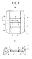
- FIG. 1(a) and FIG. 1(b) are respectively a plan view illustrating an example of a seat pad according to the present invention, and a sectional view of the seat pad of the example taken along the line A-A in FIG. 1(a) .
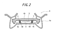
- FIG. 2 is a sectional view of a mold for forming the seat pad of the example at a position corresponding to the line A-A in FIG. 1(a) .
- FIG. 3 is a perspective view illustrating a part of a cavity in a lower mold of the mold.
- a reference number 1 represents a seat pad
- a reference number 2 represents a pad body
- a reference number 3 represents a supporter member
- a reference number 4 represents a fastener member
- a reference number 5 represents a ventilation member
- the seat pad 1 includes: a pad body 2; a supporter member 3 provided integrally with a rear surface (a surface facing upward in FIG. 1(b) ) of the pad body 2; a tape-like (sheet-like) fastener member 4 provided integrally with a seat surface of the pad body 2 surrounded by a vertical engagement groove 2a and a horizontal engagement groove 2b extending in a ladder form on a front surface (a surface facing downward in FIG.
- the fastener member 4 extending so as to be parallel to the horizontal engagement groove 2b; and, ventilation members 5 embedded in the pad body 2 so as to be positioned in the vicinity of the end portions on both sides of the fastener member 4.
- the supporter member 3 is made of a breathable nonwoven fabric having a thickness, for example, in the range of 0.2 mm to 5 mm.
- the fastener member 4 is formed by a surface fastener having a tape-like (sheet-like) urethane foam in an integral manner on a face opposite to an engagement face of a surface fastener body, the tape-like urethane foam being provided for improving the resistance to detachment.
- the ventilation members 5 are formed by a block-like slab urethane foam having, for example, a vertical slit as illustrated on the right side in FIG. 3 and, for example, dimensions of length of 30 mm, width of 30 mm and height in the range of 30 mm to 50 mm.
- each of the ventilation members 5 extends in the pad body 2 between the two end portions.
- the pad body 2 is made mainly of polyhydroxy compound and polyisocyanate compound, and is formed such that a polyurethane foaming raw material obtained by adding auxiliary agents such as foaming agent, foam stabilizer and catalyzer to these compounds depending on applications is supplied into the cavity of the mold 6 as illustrated in FIG. 2 and FIG. 3 , and, the supplied polyurethane foaming raw material is foamed and solidified in the cavity.
- the mold 6 has a lower mold 6a for mainly forming a front surface side of the pad body 2, and an upper mold 6b for mainly forming a rear surface side of the pad body 2.
- the mold 6 further has protrusions 6c formed on the lower mold 6a for forming a vertical and horizontal engagement grooves 2a and 2b on the front surface of the pad body 2, and pins 6d provided for positioning the fastener member 4 and each standing at a side of each of the end portions of a predetermined set position of the fastener member located in a center position surrounded by the protrusions 6c for forming the vertical and horizontal engagement grooves 2a and 2b. Further, a gas discharging hole, which is not shown, is provided at a position where the supporter member is attached on the upper mold 6b.
- the upper mold 6b and the lower mold 6a of the mold 6 are set to be in a mold opening position; the fastener member 4 is set at the predetermined set position in the center portion of the lower mold 6a as illustrated in FIG. 2 and FIG. 3 ; as illustrated in FIG. 2 , the ventilation members 5 are set to the respective pins 6d such that each of the pins 6d is clamped by means of the slip provided to each of the ventilation members 5 as exemplarily illustrated on a right side in FIG. 3 ; the supporter member 3 is set to the upper mold 6b so as to cover the inner surface of the upper mold 6b as illustrated in FIG.
- the polyurethane foaming raw material is supplied into the lower mold 6a, and the upper mold 6b is mold closed to the lower mold 6a to define a cavity corresponding to the seat pad 1 in the mold 6; and, the polyurethane foaming raw material is foamed and solidified in the cavity, thereby expansion molding the pad body 2 integrally with the fastener member 4 and the supporter member 3.
- the upper mold 6b and the lower mold 6a of the mold 6 are mold opened to remove the seat pad 1 from the lower mold 6a, and the seat pad 1 is take off from the upper mold 6b while being expanded.
- the seat pad 1 it is possible to form the seat pad 1 according to this example.
- the gas trapped in the pad body 2 moves from the one end portions of the ventilation members 5 located in the vicinity of the end portions on both sides of the fastener member 4, where the gas is likely to be trapped, through the other end portions of the ventilation members 5, and is discharged from the rear surface side of the pad body 2 through the mating surface between the upper mold 6b and the lower mold 6a or the gas discharging hole to the outside of the mold.
- the seat pad 1 of this example it is possible to reliably prevent the occurrence of the void in the vicinity of the end portions on both sides of the fastener member 4 in the pad body 2 without causing clogging of the gas discharging groove of the mold with the resin, a trouble caused by falling of the insert reinforce member the placement of the film, and the like.
- the fastener member 4 is formed integrally with the urethane foam so as to enhance the strength against detachment from the pad body 2, the gas that is likely to be trapped in the urethane foam can be discharged to the outside of the mold 6, whereby it is possible to reliably prevent the occurrence of the void in the pad body 2 while enhancing the strength of the fastener member 4 against detachment from the pad body 2.
- the resin raw material intrudes the space, whereby it is possible to ensure the strength of adhering the fastener member 4 to the pad body 2, as well as the strength against detachment from the pad body 2.
- the supporter member 3 having breathability is provided on the rear surface of the pad body 2, it is possible to maintain, within the supporter member 3, the gas gathered on the rear surface side of the pad body 2 through the ventilation members 5, or discharge the gathered gas through the mating surface between the upper mold 6b and the lower mold 6a, the gas discharging hole and the like to the outside of the mold 6 while preventing, by the supporter member 3, the leakage of the resin raw material to the outside of the mold 6, whereby the occurrence of the void in the vicinity of the end portions on both sides of the fastener member 4 in the pad body 2 can be further reliably prevented.
- the ventilation member 5 is provided in the vicinity of the end portion of the fastener member 4 in the longitudinal direction, where the void is likely to occur. Further, it is preferable to provided a pair of ventilation members 5 in the vicinity of the respective end portions of the fastener member 4 in the longitudinal direction as exemplarily illustrated in FIG. 1 to suppress the effect of arrangement of the ventilation member 5 on quality of the product seat pad while effectively suppressing the occurrence of the void.
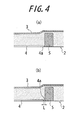
- the ventilation members 5 and the fastener member 4 may be arranged so as not to overlap with each other on a projection surface on which the ventilation member 5 and the fastener member 4 are projected toward the front surface side of the pad body 2. In this case, it is preferable to arrange the ventilation members 5 such that the lower end portions of the ventilation members 5 are located within the thickness of the fastener member 4, and it is more preferable to expose the lower end portions of the ventilation members 5 from the pad body 2 as exemplarily illustrated in the enlarged sectional view of FIG. 4 .
- the fastener member 4 and the ventilation member 5 do not overlap with each other, and, the ventilation member 5 are disposed so as to be exposed from the surface of the pad body 2, and to contact with an end edge 4a of the fastener member 4.
- the end portion of the fastener member is disposed sufficiently near to the ventilation member 5, the gas contained in the vicinity of the end portion of the fastener member is easily discharged through the ventilation member 5 to the outside of the mold, thereby effectively suppressing the occurrence of the void.
- the fastener member 4 and the ventilation member 5 do not overlap with each other, the fastener member 4 is expansion molded integrally with the pad body 2 in a strong manner, whereby it is possible to effectively prevent the detachment of the fastener member 4 from the pad body 2.
- the ventilation member 5 is exposed from the surface of the pad body 2, and is disposed at the right side of the end edge 4a of the fastener member 4 in the drawing so as to be spaced from the end edge 4a of the fastener member 4. It is preferable that the space distance L from the ventilation member 5 to the end edge 4a of the fastener member 4 is set to 17 mm or lower in order to effectively discharge the gas at the end portion of the fastener member 4 through the ventilation member 5 at the time of expansion molding. With such an arrangement, the resin raw material sufficiently intrudes between the end edge 4a of the fastener member 4 and the ventilation member 5, whereby it is possible to further enhance the strength against detachment of the fastener member 4 from the pad body 2.
- the fastener member 4 is formed with a layered structure having plural layers in which a porous layer such as a sheet-like urethane foam, nonwoven fabric and woven fabric, a film, a hair-like layer and the like are combined with the surface fastener, which is not illustrated, the gas accumulated between the layers is pushed out from the end portion of the fastener member 4 at the time when the polyurethane foam raw material is foamed and solidified, whereby the void is likely to occur especially in the vicinity of the end portion of the fastener member 4. In such a case, it is extremely effective to dispose the ventilation member 5 in the vicinity of the end portion of the fastener member 4.
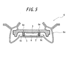
- FIG. 5 is a sectional view of a mold for forming the other example of the seat pad of the present invention, which is taken at the position corresponding to the line A-A in FIG. 1(a) .
- the seat pad 1 according to this example has the same configuration as the previously described example except that, in the seat pad according to this example, both end portions of the ventilation members 5 contact with the fastener member 4 disposed on the front surface side of the seat pad 2 and the breathable supporter member 3 disposed on the rear surface side of the seat pad 2.
- the pad body 2 is expansion molded integrally with the surface fastener 4 and the supporter member 3 such that: the pins 6d (see FIG. 2 ) on the lower mold 6a of the mold 6 for positioning the surface fastener 4 are shortened; instead of setting the ventilation members 5 to the pins 6d, needles 6e penetrating the supporter member 3 and projected into the inside of the cavity are provided on the upper mold 6b of the mold 6; the needles 6e are inserted into the ventilation members 5 to support the ventilation members 5; the ventilation members 5 are set at positions corresponding to the respective end portions of the surface fastener 4 set on the lower mold 6a as illustrated in FIG.
- the upper end portions of the ventilation members 5 contact with the supporter member 3 set on the upper mold 6b; the lower end portions of the ventilation members 5 are disposed so as to contact with the end portions on both sides of the surface fastener 4; and, the polyurethane foaming raw material is foamed and solidified in the cavity of the mold 6.
- the seat pad 1 As is the case with the previously described example, it is possible to reliably prevent the occurrence of the void in the vicinity of the end portions on both sides of the surface fastener 4 in the pad body 2 without causing the clogging of the gas discharging groove of the mold with the resin, a trouble caused by falling of the insert reinforce member, placement of the film, and the like.
- the needle 6e provided to the upper mold 6b in a cylindrical shape so as to penetrate the upper mold 6b, and employ the needle 6e in place of the gas discharging hole of the upper mold 6b.
- the fastener member 4 at the bottom portion of the engagement grooves 2a and 2b, in place of or in addition to in the seat surface surrounded by the engagement grooves 2a and 2b on the front surface side of the pad body 2.
- the end portions of plural fastener members 4 may be gathered in the vicinity of the intersecting portion of the engagement grooves 2a and 2b, and dispose the one end portion of the ventilation member 5 in the vicinity of the gathered end portions of the fastener members 4.
- the intersecting portion of the engagement grooves 2a and 2b is displaced from the center of the seat pad 1, and is less likely to contact with a human body at the time of sitting on the seat, whereby a seated person does not feel any discomfort at all, or feels hardly any discomfort even in the case where the fastener member 4 or the ventilation member 5 is relatively hard as compared with the pad body 2.
- a seat pad of Example 1 was manufactured by using a mold similar to that shown in FIG. 2 , and has a configuration illustrated in FIG. 1 .
- the ventilation members 5 and the fastener member 4 which is a surface fastener made of resin, are overlapped with each other on a projection surface on which the ventilation members 5 and the fastener member 4 are projected toward the front surface side of the pad body 2.
- a length of each space between the end portions on the lower side of the ventilation members 5 and the rear surface of each of the end portions on both sides of the fastener member 4 is set to 0 mm, in other words, no space is provided between them.
- thicknesses of the seat pad 1 at positions of respective end portions of the fastener member 4 formed integrally with the front surface of the seat pad 1 are set to 70 mm.
- Seat pads of Examples 2 to 7 each have the same configuration as the seat pad of Example 1 except that, in these Examples, a length in the vertical direction in the drawing of each space between the end portions on the lower side of the ventilation members 5 and the rear surface of each of the end portions on both sides of the fastener member 4 varies as illustrated in Table 1, and, the end portions on the lower side of the ventilation members 5 are disposed so as to be embedded in the pad body 2.
- a seat pad of Example 8 has the same configuration as the seat pad of Example 1 except that, in Example 8, as illustrated in FIG. 4(a) , the fastener member 4 and the ventilation members 5 do not overlap with each other on a projection surface on which the fastener member 4 and the ventilation members 5 are projected toward the front surface of the pad body 2, and the ventilation members 5 are disposed so as to be exposed from the surface of the pad body 2, and to contact with the end edge 4a of the fastener member 4.
- the seat pad of Example 8 has the same configuration as the seat pad of Example 8 except that, in Example 8, as illustrated in FIG. 4(b) , the space distance L of the ventilation member 5 from the end edge 4a of the fastener member 4 is set to 15 mm. Further, the seat pad of Example 9 has the same configuration as the seat pad of Example 8 except that this space distance L is set to 17 mm.
- a detaching force of 20 N with respect to the pad body 2 is applied to the fastener member 4 while the end portion of the fastener member 4 is being gripped.
- the results thereof are shown in Table 1. Note that, in Table 1, the mark O1 represents that there is no detaching portion; 02 represents that, although the detachment does not grow and the degree of detachment is not a problem, slight detachment occurs in an area where the end portion of the fastener member 4 contacts with the ventilation member 5.
- the length of each of the spaces between the end portions on the lower side of the ventilation members 5 and the rear surface of the end portions on both sides of the fastener member 4 is preferably set in the range of 0 mm to 17 mm from the viewpoint of the discharge of the gas and the strength against the detachment, more preferably, in the range of 1 mm to 17 mm, and yet more preferably, in the range of 1 mm to 15 mm.
- the seat pad of the present invention it is possible to reliably prevent the occurrence of the void in the vicinity of the fastener member of the pad body, without causing the clogging of the gas discharging groove of the mold with the resin, a trouble caused by falling of the insert reinforce member, a trouble occurring at the time of setting the film, and the like.
Landscapes
- Engineering & Computer Science (AREA)
- Mechanical Engineering (AREA)
- Manufacturing & Machinery (AREA)
- Aviation & Aerospace Engineering (AREA)
- Transportation (AREA)
- Mattresses And Other Support Structures For Chairs And Beds (AREA)
- Casting Or Compression Moulding Of Plastics Or The Like (AREA)
- Chair Legs, Seat Parts, And Backrests (AREA)
Abstract
Description
- The present invention relates to a seat pad used in a seat and the like of a vehicle, and in particular, to a seat pad in which occurrence of a void (an air gap) in a pad body made of a foamed resin is prevented.
- In general, a seat pad used in a seat and the like of a vehicle has a fastener member on a front surface side of a pad body made of a foamed resin in order to engage and secure surface skins. This seat pad is generally formed such that: the fastener member, a supporter member to be provided on the rear surface side of the pad body and the like are placed in a cavity provided in a mold and having a shape in which a front surface side of the pad body faces downward; and, a resin raw material such as raw solution of urethane foam is foamed and solidified in the cavity, whereby the pad body is foamed and shaped to integrated with the fastener member, the supporter member and the like.
- It was found that there is a problem in the above-described mold that, since the fastener member is placed in the cavity on a lower mold side in order to attach the fastener member on the front surface side of the pad body, the resin is likely to trap gas in the vicinity of the fastener, especially, in the vicinity of an end portion of the fastener at the time of foaming and solidifying the resin raw material, and, in the case where an engagement groove is provided on the front surface side of the pad body and the fastener member is placed at the bottom of the groove, the resin is likely to contain gas in the vicinity of an intersecting point of protrusions for forming the engagement groove, whereby voids (air gaps) are likely to occur in the pad body in the vicinity of the fastener member, especially in the vicinity of the end portion of the fastener portion.
- Conventionally, various countermeasures against occurrence of the voids have been attempted. For example, Patent Document 1 describes that an opening is provided in the vicinity of the intersecting point of protrusions of the cavity of the mold, and a groove for discharging the gas is formed at the lower portion thereof. Further,
Patent Document 2 describes that the gas is discharged by using a nonwoven fabric placed at the upper portion in the cavity of the mold. Yet further,Patent Document 3 describes that the gas is discharged from the gas discharging tube through an insert reinforce member located at the upper and center portion in the cavity of the mold and supported by the upper mold. Yet further,Patent Document 4 describes that a flexible-polyurethane foam layer attached to a surface fastener serving as the fastener member provided to the pad body is covered with an elastomer film in order to prevent containment of the gas occurring due to entry of the resin raw material of the pad body into the flexible-polyurethane foam. -
- Patent Document 1: Japanese Patent Application Laid-open No.
2008-168446 - Patent Document 2: Japanese Patent Application Laid-open No.
2000-233414 - Patent Document 3: Japanese Patent Application Laid-open No.
08-174575 - Patent Document 4: Japanese Patent Application Laid-open No.
2002-210272 - However, with the countermeasure described in Patent Document 1, the gas cannot be discharged when the urethane clogs the gas discharging groove, requiring a lot of work for doing maintenance for preventing the clogging. Further, with the countermeasure described in
Patent Document 2, although the gas existing in the vicinity of the upper portion of the cavity of the mold is discharged, it is still not sufficient to discharge the gas in the vicinity of the protrusion at the lower portion of the cavity of the mold. Yet further, with the countermeasure described inPatent Document 3, an extremely large insert reinforce member is required for discharging the gas in the vicinity of the protrusion at the lower portion of the cavity of the mold, and when receiving a large force arising from foaming of the resin raw material of the pad body, the extremely large insert reinforce member falls upon the seat pad, which causing the deterioration of quality of the seat pad. Yet further, with the countermeasure described inPatent Document 4, the excessive covering of the flexible-polyurethane foam with the elastomer film renders the strength against detachment of the surface fastener undesirably low, whereas the insufficient area covering renders the resin raw material excessively intrude the flexible-polyurethane foam layer, which makes it impossible to prevent the gas from being enclosed. Therefore, in any of the cases describe above, the countermeasures for the voids were not sufficient. - An object of the present invention is to advantageously solve the problems described above, and the present invention provides a seat pad having a fastener member on a front surface side of a pad body made of foaming resin, which includes a ventilation member, one end portion of the ventilation member being located in the vicinity of the fastener member, and the other end portion of the ventilation member extending on a rear surface side of the pad body.
- According to the seat pad of the present invention, during a time when a resin raw material is being foamed and solidified in a cavity of a mold for expansion molding the pad body, gas moves from the one end portion of the ventilation member located in the vicinity of the fastener member in the pad body where the gas is likely to be trapped, to the other end portion of the ventilation member. Then, the gas passes from the rear surface side of the pad body through a mating surface between the upper and lower molds, a gas discharging hole and the like, and is discharged to the outside of the mold.
- Therefore, according to the seat pad of the present invention, it is possible to reliably prevent occurrence of the void in the vicinity of the fastener member, especially in the vicinity of the end portion of the fastener member in the pad body without causing clogging of the gas discharging groove of the mold with the resin, a trouble caused by falling of the insert reinforce member, a trouble due to the placement of the film, and the like. In this specification, the pad body can be formed by foaming and solidifying the resin raw material such as polyurethane, polyethylene and polystyrene, and as the fastener member, it may be possible to employ, for example, a surface fastener and hanging wire. Further, as the ventilation member, it may be possible to employ a slab urethane, nonwoven fabric, felt, and resin hose, and it may be possible to support the ventilation member by any of the upper mold and the lower mold of the mold for expansion molding the pad body.
- It should be noted that, according to the seat pad of the present invention, the fastener member may be formed integrally with urethane foam or nonwoven fabric so as to enhance the strength against detachment from the pad body. With this configuration, it is possible to discharge the gas, which is likely to be trapped in the urethane foam or nonwoven fabric, to the outside of the mold, whereby it is possible to reliably prevent the occurrence of the void in the pad body while enhancing the strength against detachment of the fastener member relative to the pad body.
- Further, according to the seat pad of the present invention, the fastener member may be disposed at a bottom portion of an engagement groove provided on a front surface side of the pad body. With this configuration, it is possible to evacuate, to the outside of the mold, the gas that is likely to be contained in bottom portions of engagement grooves corresponding to the top end portions of the protrusions provided on the lower mold and forming the engagement grooves, the containment of the gas being caused by delay in the resin raw material arriving in the vicinity of the top portions of the protrusions, whereby it is possible to further reliably prevent the occurrence of the void in the pad body.
- Yet further, according to the seat pad of the present invention, it may be possible that end portions of plural fastener members are arranged so as to be gathered in the vicinity of an intersecting portion of the engagement grooves; and, the one end portion of the ventilation member is disposed in the vicinity of the gathered end portions of the fasteners. With this configuration, the intersecting portion of the engagement grooves is displaced from the center of the seat pad, and is less likely to contact with a human body at the time of sitting on the seat, whereby a seated person does not feel any discomfort at all, or feels hardly any discomfort even in the case where the fastener member or the ventilation member is relatively hard as compared with the pad body.
- Yet further, according to the seat pad of the present invention, the fastener member and the one end portion of the ventilation member may be arranged so as to be spaced at a distance in the range of 1 mm to 17 mm. With this configuration, the resin raw material can enter the space, whereby it is possible to secure the strength of adhering of the fastener member with the pad body, and the strength against detachment of the fastener member from the pad body.
- Yet further, according to the seat pad of the present invention, the ventilation member and the fastener member may be arranged so as not to overlap with each other on a projection surface on which the ventilation member and the fastener member are projected toward the front surface side of the pad body. With this configuration, since the ventilation member and the fastener member do not overlap with each other, the fastener member can be strongly integrated with the pad member, whereby it is possible to effectively prevent the fastener member from detaching from the pad body.
- Yet further, according to the seat pad of the present invention, the one end portion of the ventilation member may contact with or integrated with the urethane foam of the fastener member. With this configuration, the gas occurring from the urethane foam in the fastener member due to intrusion of the resin raw material can be discharged through the ventilation member to the outside of the mold, whereby it is possible to further reliably prevent the occurrence of the void in the pad body.
- Yet further, according to the seat pad of the present invention, a supporter member having breathability may be provided on a rear surface of the pad body. With this configuration, the gas gathering on the rear surface side of the pad body through the ventilation member can be maintained within the supporter member, or can be discharged to the outside of the mold through the mating surface between the upper mold and the lower mold or gas discharging hole while preventing, by the supporter member, the leakage of the resin raw material to the outside of the mold, whereby it is possible to further reliably prevent the occurrence of the void in the vicinity of the engagement groove of the pad body.
As the supporter having the breathability, it may be possible to employ, for example, a woven fabric or nonwoven fabric. -
-
FIG. 1(a) and FIG. 1(b) are respectively a plan view illustrating an example of a seat pad according to the present invention, and a sectional view of the seat pad of the example taken along the line A-A inFIG. 1(a) . -
FIG. 2 is a sectional view of a mold for forming the seat pad of the above-described example at a position corresponding to the line A-A inFIG. 1(a) . -
FIG. 3 is a perspective view illustrating a part of a cavity in a lower mold of the mold. -
FIG. 4 is an enlarged sectional view taken along the line A-A and illustrating a modification example of arrangement of the ventilation member in the seat pad. -
FIG. 5 is a sectional view of a mold for forming a seat pad of the other example of the present invention at a position corresponding to the line A-A inFIG. 1(a) . - Hereinbelow, with reference to the drawings, an embodiment according to the present invention will be described in detail by way of example.
FIG. 1(a) and FIG. 1(b) are respectively a plan view illustrating an example of a seat pad according to the present invention, and a sectional view of the seat pad of the example taken along the line A-A inFIG. 1(a) .FIG. 2 is a sectional view of a mold for forming the seat pad of the example at a position corresponding to the line A-A inFIG. 1(a) .FIG. 3 is a perspective view illustrating a part of a cavity in a lower mold of the mold. In the drawings, a reference number 1 represents a seat pad; areference number 2 represents a pad body; areference number 3 represents a supporter member; areference number 4 represents a fastener member; and, areference number 5 represents a ventilation member. - As illustrated in
FIGS. 1(a) and 1(b) , the seat pad 1 according to this example includes: apad body 2; asupporter member 3 provided integrally with a rear surface (a surface facing upward inFIG. 1(b) ) of thepad body 2; a tape-like (sheet-like)fastener member 4 provided integrally with a seat surface of thepad body 2 surrounded by avertical engagement groove 2a and ahorizontal engagement groove 2b extending in a ladder form on a front surface (a surface facing downward inFIG. 1(b) ) of thepad body 2, thefastener member 4 extending so as to be parallel to thehorizontal engagement groove 2b; and,ventilation members 5 embedded in thepad body 2 so as to be positioned in the vicinity of the end portions on both sides of thefastener member 4. - The
supporter member 3 is made of a breathable nonwoven fabric having a thickness, for example, in the range of 0.2 mm to 5 mm. Thefastener member 4 is formed by a surface fastener having a tape-like (sheet-like) urethane foam in an integral manner on a face opposite to an engagement face of a surface fastener body, the tape-like urethane foam being provided for improving the resistance to detachment. Theventilation members 5 are formed by a block-like slab urethane foam having, for example, a vertical slit as illustrated on the right side inFIG. 3 and, for example, dimensions of length of 30 mm, width of 30 mm and height in the range of 30 mm to 50 mm. Lower end portions of theventilation members 5, which are end portions on the lower side of theventilation members 5 inFIG. 1(b) , contact with a rear surface of the end portions on both sides of thefastener member 4, and are exposed from a surface of thepad body 2 or are embedded in thepad body 2 so as to be located upward and be spaced at a distance, for example, in the range of 1 mm to 17 mm from the rear surface of the end portions on both sides of thefastener member 4 inFIG. 1(b) . Further, each upper end portion of theventilation members 5, which are end portions on the upper side of theventilation members 5 inFIG. 1(b) , is spaced at a distance, for example, in the range of 1 mm to 17 mm from the lower surface of thesupporter member 3, or contacts with the lower surface of thesupporter member 3. Each of theventilation members 5 extends in thepad body 2 between the two end portions. - The
pad body 2 is made mainly of polyhydroxy compound and polyisocyanate compound, and is formed such that a polyurethane foaming raw material obtained by adding auxiliary agents such as foaming agent, foam stabilizer and catalyzer to these compounds depending on applications is supplied into the cavity of themold 6 as illustrated inFIG. 2 andFIG. 3 , and, the supplied polyurethane foaming raw material is foamed and solidified in the cavity. Themold 6 has alower mold 6a for mainly forming a front surface side of thepad body 2, and anupper mold 6b for mainly forming a rear surface side of thepad body 2. Themold 6 further hasprotrusions 6c formed on thelower mold 6a for forming a vertical andhorizontal engagement grooves pad body 2, and pins 6d provided for positioning thefastener member 4 and each standing at a side of each of the end portions of a predetermined set position of the fastener member located in a center position surrounded by theprotrusions 6c for forming the vertical andhorizontal engagement grooves upper mold 6b. - At the time of forming the seat pad 1 according to this example, first, the
upper mold 6b and thelower mold 6a of themold 6 are set to be in a mold opening position; thefastener member 4 is set at the predetermined set position in the center portion of thelower mold 6a as illustrated inFIG. 2 andFIG. 3 ; as illustrated inFIG. 2 , theventilation members 5 are set to therespective pins 6d such that each of thepins 6d is clamped by means of the slip provided to each of theventilation members 5 as exemplarily illustrated on a right side inFIG. 3 ; thesupporter member 3 is set to theupper mold 6b so as to cover the inner surface of theupper mold 6b as illustrated inFIG. 2 ; then, the polyurethane foaming raw material is supplied into thelower mold 6a, and theupper mold 6b is mold closed to thelower mold 6a to define a cavity corresponding to the seat pad 1 in themold 6; and, the polyurethane foaming raw material is foamed and solidified in the cavity, thereby expansion molding thepad body 2 integrally with thefastener member 4 and thesupporter member 3. Then, after the polyurethane foaming raw material solidifies, theupper mold 6b and thelower mold 6a of themold 6 are mold opened to remove the seat pad 1 from thelower mold 6a, and the seat pad 1 is take off from theupper mold 6b while being expanded. - With this configuration, it is possible to form the seat pad 1 according to this example. At the time of forming the seat pad 1 according to this example, during the time when the polyurethane foam raw material is being foamed and solidified in the cavity of the
mold 6, the gas trapped in thepad body 2 moves from the one end portions of theventilation members 5 located in the vicinity of the end portions on both sides of thefastener member 4, where the gas is likely to be trapped, through the other end portions of theventilation members 5, and is discharged from the rear surface side of thepad body 2 through the mating surface between theupper mold 6b and thelower mold 6a or the gas discharging hole to the outside of the mold. - Therefore, according to the seat pad 1 of this example, it is possible to reliably prevent the occurrence of the void in the vicinity of the end portions on both sides of the
fastener member 4 in thepad body 2 without causing clogging of the gas discharging groove of the mold with the resin, a trouble caused by falling of the insert reinforce member the placement of the film, and the like. - Further, according to the seat pad 1 of this example, since the
fastener member 4 is formed integrally with the urethane foam so as to enhance the strength against detachment from thepad body 2, the gas that is likely to be trapped in the urethane foam can be discharged to the outside of themold 6, whereby it is possible to reliably prevent the occurrence of the void in thepad body 2 while enhancing the strength of thefastener member 4 against detachment from thepad body 2. - Yet further, according to the seat pad 1 of this example, in the case where the lower end portions of the
ventilation members 5, which are end portions on the lower side of theventilation members 5 inFIG. 1(b) , are embedded in thepad body 2, and are located upward inFIG. 1(b) so as to be spaced, for example, in the range of 1 mm to 17 mm from the rear surface of the end portions on both sides of thefastener member 4, the resin raw material intrudes the space, whereby it is possible to ensure the strength of adhering thefastener member 4 to thepad body 2, as well as the strength against detachment from thepad body 2. In this case, it is possible to discharge the gas that is likely to be contained in the end portions of thefastener member 4, through theventilation members 5 to the outside of themold 6, even if the lower end portions of theventilation members 5 are spaced from thefastener member 4. On the other hand, in the case where the lower end portions of theventilation members 5, which are end portions on the lower side of theventilation members 5 inFIG. 1(b) , contact with the rear surface of the end portions on both sides of thefastener member 4, or are formed integrally with the tape-like urethane foam provided on the rear surface of thefastener member 4, it is possible to discharge the gas occurring from the urethane foam of thefastener member 4 due to intrusion of the resin raw material, through theventilation members 5 to the outside of themold 6, whereby the occurrence of the void in thepad body 2 can be further reliably prevented. - Yet further, according to the seat pad of this example, since the
supporter member 3 having breathability is provided on the rear surface of thepad body 2, it is possible to maintain, within thesupporter member 3, the gas gathered on the rear surface side of thepad body 2 through theventilation members 5, or discharge the gathered gas through the mating surface between theupper mold 6b and thelower mold 6a, the gas discharging hole and the like to the outside of themold 6 while preventing, by thesupporter member 3, the leakage of the resin raw material to the outside of themold 6, whereby the occurrence of the void in the vicinity of the end portions on both sides of thefastener member 4 in thepad body 2 can be further reliably prevented. - It should be noted that it is preferable that the
ventilation member 5 is provided in the vicinity of the end portion of thefastener member 4 in the longitudinal direction, where the void is likely to occur. Further, it is preferable to provided a pair ofventilation members 5 in the vicinity of the respective end portions of thefastener member 4 in the longitudinal direction as exemplarily illustrated inFIG. 1 to suppress the effect of arrangement of theventilation member 5 on quality of the product seat pad while effectively suppressing the occurrence of the void. - The
ventilation members 5 and thefastener member 4 may be arranged so as not to overlap with each other on a projection surface on which theventilation member 5 and thefastener member 4 are projected toward the front surface side of thepad body 2. In this case, it is preferable to arrange theventilation members 5 such that the lower end portions of theventilation members 5 are located within the thickness of thefastener member 4, and it is more preferable to expose the lower end portions of theventilation members 5 from thepad body 2 as exemplarily illustrated in the enlarged sectional view ofFIG. 4 . - In the seat pad 1 illustrated in
FIG. 4(a) , thefastener member 4 and theventilation member 5 do not overlap with each other, and, theventilation member 5 are disposed so as to be exposed from the surface of thepad body 2, and to contact with anend edge 4a of thefastener member 4. In this case, since the end portion of the fastener member is disposed sufficiently near to theventilation member 5, the gas contained in the vicinity of the end portion of the fastener member is easily discharged through theventilation member 5 to the outside of the mold, thereby effectively suppressing the occurrence of the void. Further, since thefastener member 4 and theventilation member 5 do not overlap with each other, thefastener member 4 is expansion molded integrally with thepad body 2 in a strong manner, whereby it is possible to effectively prevent the detachment of thefastener member 4 from thepad body 2. - In the seat pad illustrated in
FIG. 4(b) , theventilation member 5 is exposed from the surface of thepad body 2, and is disposed at the right side of theend edge 4a of thefastener member 4 in the drawing so as to be spaced from theend edge 4a of thefastener member 4. It is preferable that the space distance L from theventilation member 5 to theend edge 4a of thefastener member 4 is set to 17 mm or lower in order to effectively discharge the gas at the end portion of thefastener member 4 through theventilation member 5 at the time of expansion molding. With such an arrangement, the resin raw material sufficiently intrudes between theend edge 4a of thefastener member 4 and theventilation member 5, whereby it is possible to further enhance the strength against detachment of thefastener member 4 from thepad body 2. - In the case where the
fastener member 4 is formed with a layered structure having plural layers in which a porous layer such as a sheet-like urethane foam, nonwoven fabric and woven fabric, a film, a hair-like layer and the like are combined with the surface fastener, which is not illustrated, the gas accumulated between the layers is pushed out from the end portion of thefastener member 4 at the time when the polyurethane foam raw material is foamed and solidified, whereby the void is likely to occur especially in the vicinity of the end portion of thefastener member 4. In such a case, it is extremely effective to dispose theventilation member 5 in the vicinity of the end portion of thefastener member 4. -
FIG. 5 is a sectional view of a mold for forming the other example of the seat pad of the present invention, which is taken at the position corresponding to the line A-A inFIG. 1(a) . InFIG. 5 , portions identical to those of the previously described example are denoted with identical reference numerals. More specifically, the seat pad 1 according to this example has the same configuration as the previously described example except that, in the seat pad according to this example, both end portions of theventilation members 5 contact with thefastener member 4 disposed on the front surface side of theseat pad 2 and thebreathable supporter member 3 disposed on the rear surface side of theseat pad 2. - Further, at the time of forming the seat pad 1 according to this example, the
pad body 2 is expansion molded integrally with thesurface fastener 4 and thesupporter member 3 such that: thepins 6d (seeFIG. 2 ) on thelower mold 6a of themold 6 for positioning thesurface fastener 4 are shortened; instead of setting theventilation members 5 to thepins 6d, needles 6e penetrating thesupporter member 3 and projected into the inside of the cavity are provided on theupper mold 6b of themold 6; theneedles 6e are inserted into theventilation members 5 to support theventilation members 5; theventilation members 5 are set at positions corresponding to the respective end portions of thesurface fastener 4 set on thelower mold 6a as illustrated inFIG. 5 ; the upper end portions of theventilation members 5 contact with thesupporter member 3 set on theupper mold 6b; the lower end portions of theventilation members 5 are disposed so as to contact with the end portions on both sides of thesurface fastener 4; and, the polyurethane foaming raw material is foamed and solidified in the cavity of themold 6. - With the seat pad 1 according to this example, as is the case with the previously described example, it is possible to reliably prevent the occurrence of the void in the vicinity of the end portions on both sides of the
surface fastener 4 in thepad body 2 without causing the clogging of the gas discharging groove of the mold with the resin, a trouble caused by falling of the insert reinforce member, placement of the film, and the like. - Although descriptions have been made on the basis of the examples with reference to the drawings, the present invention is not limited to the examples described above, and depending on application, may be changed within the range of description in claims. For example, it may be possible to employ a foaming raw material such as polyethylene and polystyrene for the resin raw material for expansion molding the
pad body 2, rather than the polyurethane foaming raw material; employ a woven fabric for thesupporter member 3, rather than the nonwoven fabric; form the fastener member integrally with a nonwoven fabric, in place of the urethane foam, for enhancing the strength against detachment of thefastener member 4 from thepad body 2; and, form theventilation member 5 by a hair felt or nonwoven fabric as illustrated on the left inFIG. 3 or resin hose, rather than the block-like slab urethane foam. Further, it may be possible to form theneedle 6e provided to theupper mold 6b in a cylindrical shape so as to penetrate theupper mold 6b, and employ theneedle 6e in place of the gas discharging hole of theupper mold 6b. - Further, it may be possible to dispose the
fastener member 4 at the bottom portion of theengagement grooves engagement grooves pad body 2. With this configuration, it is possible to evacuate, to the outside of themold 6, the gas that is likely to be contained in the bottom portions of theengagement grooves protrusions 6c provided on thelower mold 6a for forming theengagement grooves protrusions 6c, whereby it is possible to further reliably prevent the occurrence of the void in thepad body 2. In this case, it may be possible to arrange the end portions ofplural fastener members 4 so as to be gathered in the vicinity of the intersecting portion of theengagement grooves ventilation member 5 in the vicinity of the gathered end portions of thefastener members 4. With this configuration, the intersecting portion of theengagement grooves fastener member 4 or theventilation member 5 is relatively hard as compared with thepad body 2. - Next, description will be made of results of evaluation on performances of the seat pad according to the present invention.
A seat pad of Example 1 was manufactured by using a mold similar to that shown inFIG. 2 , and has a configuration illustrated inFIG. 1 . In this seat pad according to Example 1, inFIG. 1(b) , theventilation members 5 and thefastener member 4, which is a surface fastener made of resin, are overlapped with each other on a projection surface on which theventilation members 5 and thefastener member 4 are projected toward the front surface side of thepad body 2. Further, a length of each space between the end portions on the lower side of theventilation members 5 and the rear surface of each of the end portions on both sides of thefastener member 4 is set to 0 mm, in other words, no space is provided between them.
Yet further, thicknesses of the seat pad 1 at positions of respective end portions of thefastener member 4 formed integrally with the front surface of the seat pad 1 are set to 70 mm. - Seat pads of Examples 2 to 7 each have the same configuration as the seat pad of Example 1 except that, in these Examples, a length in the vertical direction in the drawing of each space between the end portions on the lower side of the
ventilation members 5 and the rear surface of each of the end portions on both sides of thefastener member 4 varies as illustrated in Table 1, and, the end portions on the lower side of theventilation members 5 are disposed so as to be embedded in thepad body 2. - A seat pad of Example 8 has the same configuration as the seat pad of Example 1 except that, in Example 8, as illustrated in
FIG. 4(a) , thefastener member 4 and theventilation members 5 do not overlap with each other on a projection surface on which thefastener member 4 and theventilation members 5 are projected toward the front surface of thepad body 2, and theventilation members 5 are disposed so as to be exposed from the surface of thepad body 2, and to contact with theend edge 4a of thefastener member 4. - The seat pad of Example 8 has the same configuration as the seat pad of Example 8 except that, in Example 8, as illustrated in
FIG. 4(b) , the space distance L of theventilation member 5 from theend edge 4a of thefastener member 4 is set to 15 mm. Further, the seat pad of Example 9 has the same configuration as the seat pad of Example 8 except that this space distance L is set to 17 mm. - For the seat pads of Examples described above, evaluation has been made on the effect of the gas discharging by the
ventilation member 5, by visually inspecting the presence or absence of the void resulting from the gas contained in the vicinity of the end portion of thefastener member 4 at the time of expansion molding the seat pad. The results thereof are shown in Table 1. Note that, in Table 1, the mark O1 represents that the void does not occur; the mark 02 represents that the void cannot be recognized at first glance but the small amount of the void can be recognized when carefully watching the sample; and, the mark X represents that occurrence of the void can be recognized even at a glance. - Further, in order to evaluate the strength against detachment of the
fastener member 4 from thepad body 2, a detaching force of 20 N with respect to thepad body 2 is applied to thefastener member 4 while the end portion of thefastener member 4 is being gripped. The results thereof are shown in Table 1. Note that, in Table 1, the mark O1 represents that there is no detaching portion; 02 represents that, although the detachment does not grow and the degree of detachment is not a problem, slight detachment occurs in an area where the end portion of thefastener member 4 contacts with theventilation member 5. -
[Table 1] Length of space (mm) Space distance L (mm) Evaluation results Gas discharging effect Strength against detachment Example 1 0 - O1 O2 Example 2 1 - O1 O1 Example 3 5 - O1 O1 Example 4 10 - O1 O1 Example 5 15 - O1 O1 Example 6 17 - O2 O1 Example 7 20 - X O1 Example 8 - 0 O1 O1 Example 9 - 15 O1 O1 Example 10 - 17 02 O1 - From the results of the seat pads of Examples 1 to 7 in Table 1, it can be known that the smaller length of the space between the end portions on the lower side of the
ventilation members 5 and the rear surface of the end portions on both sides of thefastener member 4 exhibits the better gas discharging effect. In particular, it can be known that, in the case where this length is set to 17 mm or lower, the gas in the vicinity of the end portions of thefastener member 4 is sufficiently discharged through theventilation members 5 at the time of expansion molding, whereby it is possible to suppress the occurrence of the void in the seat pad 1. Further, in particular, in the case where this length is set to 15 mm or lower, it is possible to further suppress the occurrence of the void in the seat pad 1.
Further, although detachment cannot be found in the samples except for the contact portion between thefastener member 4 and theventilation member 5 and the degree of detachment is not a problem, it is preferable to set a space of 1 mm or more from the viewpoint of eliminating the detachment.
From these results, it is found that the length of each of the spaces between the end portions on the lower side of theventilation members 5 and the rear surface of the end portions on both sides of thefastener member 4 is preferably set in the range of 0 mm to 17 mm from the viewpoint of the discharge of the gas and the strength against the detachment, more preferably, in the range of 1 mm to 17 mm, and yet more preferably, in the range of 1 mm to 15 mm. - From the results of the seat pads of Examples 8 to 10 in Table 1, it can be known that, in the case where the
ventilation members 5 and thefastener member 4 do not overlap with each other and the end portions on the lower side of theventilation members 5 are disposed so as to be exposed from thepad body 2, it is possible to obtain sufficient strength against detachment of thefastener member 4 from thepad body 2, and in terms of discharge of the gas, the occurrence of the void in the seat pad 1 can be suppressed when the length L is set to 17 mm or lower. - As described above, according to the seat pad of the present invention, it is possible to reliably prevent the occurrence of the void in the vicinity of the fastener member of the pad body, without causing the clogging of the gas discharging groove of the mold with the resin, a trouble caused by falling of the insert reinforce member, a trouble occurring at the time of setting the film, and the like.
-
- 1
- Seat pad
- 2
- Pad body
- 2a
- Vertical engagement groove
- 2b
- Horizontal engagement groove
- 3
- Supporter member
- 4
- Fastener member
- 4a
- End edge of fastener member
- 5
- Ventilation member
- 6
- Mold
- 6a
- Lower mold
- 6b
- Upper mold
- 6c
- Protrusion
- 6d
- Pin
- 6e
- Needle
Claims (8)
- A seat pad having a fastener member on a front surface side of a pad body made of foaming resin, comprising:a ventilation member, one end portion of the ventilation member being located in the vicinity of the fastener member, and the other end portion of the ventilation member extending on a rear surface side of the pad body.
- The seat pad according to claim 1, wherein
the fastener member is formed integrally with a urethane foam or nonwoven fabric to enhance the strength against detachment from the pad body. - The seat pad according to claim 1 or 2, wherein
the fastener member is disposed at a bottom portion of an engagement groove provided on a front surface side of the pad body. - The seat pad according to claim 3, wherein
end portions of a plurality of fastener members are arranged to be gathered in the vicinity of an intersecting portion of the engagement groove; and,
the one end portion of the ventilation member is disposed in the vicinity of the gathered end portions of the fastener members. - The seat pad according to any one of claims 1 to 4, wherein
the fastener member and the one end portion of the ventilation member are arranged to be spaced from each other at a distance in the range of 1 mm to 17 mm, the one end portion of the ventilation member being embedded in the pad body. - The seat pad according to any one of claims 1 to 4, wherein
the ventilation member and the fastener member are arranged not to overlap with each other on a projection surface on which the ventilation member and the fastener member are projected toward the front surface side of the pad body. - The seat pad according to any one of claims 2 to 4, wherein
the one end portion of the ventilation member contacts with or integrated with the urethane foam of the fastener member. - The seat pad according to any one of claims 1 to 7, wherein
a supporter member having breathability is provided on a rear surface of the pad body.
Applications Claiming Priority (2)
| Application Number | Priority Date | Filing Date | Title |
|---|---|---|---|
| JP2009048476 | 2009-03-02 | ||
| PCT/JP2010/001373 WO2010100880A1 (en) | 2009-03-02 | 2010-03-01 | Seat pad |
Publications (2)
| Publication Number | Publication Date |
|---|---|
| EP2404530A1 true EP2404530A1 (en) | 2012-01-11 |
| EP2404530A4 EP2404530A4 (en) | 2015-04-22 |
Family
ID=42709449
Family Applications (1)
| Application Number | Title | Priority Date | Filing Date |
|---|---|---|---|
| EP10748481.8A Withdrawn EP2404530A4 (en) | 2009-03-02 | 2010-03-01 | Seat pad |
Country Status (5)
| Country | Link |
|---|---|
| US (1) | US8864238B2 (en) |
| EP (1) | EP2404530A4 (en) |
| JP (1) | JP5567549B2 (en) |
| CN (1) | CN102413738B (en) |
| WO (1) | WO2010100880A1 (en) |
Cited By (3)
| Publication number | Priority date | Publication date | Assignee | Title |
|---|---|---|---|---|
| EP3078541A1 (en) * | 2015-04-10 | 2016-10-12 | Cera TSC | Headrest for vehicle seat |
| US9566755B2 (en) | 2011-03-28 | 2017-02-14 | Bridgestone Corporation | Foamed synthetic resin molded body and method for producing same |
| EP4050173A1 (en) * | 2021-02-25 | 2022-08-31 | Steinbach & Vollmann GmbH | Panel connector with air channel |
Families Citing this family (14)
| Publication number | Priority date | Publication date | Assignee | Title |
|---|---|---|---|---|
| JP5951439B2 (en) * | 2012-10-05 | 2016-07-13 | 東洋ゴム工業株式会社 | Seat back pad and manufacturing method thereof |
| JP6113617B2 (en) * | 2013-09-26 | 2017-04-12 | 株式会社タチエス | Breathable sheet |
| JP6154296B2 (en) * | 2013-11-19 | 2017-06-28 | 東洋ゴム工業株式会社 | Seat pad and manufacturing method thereof |
| JP6188218B2 (en) | 2013-12-11 | 2017-08-30 | 東洋ゴム工業株式会社 | Manufacturing method of seat pad |
| JP2015112231A (en) | 2013-12-11 | 2015-06-22 | 東洋ゴム工業株式会社 | Method for manufacturing seat pad |
| JP6251110B2 (en) * | 2014-04-08 | 2017-12-20 | 株式会社ブリヂストン | Seat pad |
| JP6243292B2 (en) * | 2014-05-19 | 2017-12-06 | 株式会社ブリヂストン | Seal member and seat pad manufacturing method using the seal member |
| JP6425988B2 (en) * | 2014-12-15 | 2018-11-21 | 株式会社タチエス | Seat pad and method of manufacturing seat pad |
| EP3545796A4 (en) * | 2016-11-25 | 2020-04-08 | Bridgestone Corporation | Seat pad |
| FR3062350B1 (en) * | 2017-01-31 | 2022-11-04 | Peugeot Citroen Automobiles Sa | COVER FOR MOTOR VEHICLE SEAT SEAT OR BACKREST UPHOLSTERY. |
| EP3626424A4 (en) * | 2017-05-16 | 2020-06-03 | Bridgestone Corporation | Foam molding mold and method for manufacturing foam molding body |
| US10427719B2 (en) | 2017-09-21 | 2019-10-01 | Faurecia Interior Systems, Inc. | Interior panels for motor vehicles and methods for making the same |
| US11590871B2 (en) * | 2017-12-14 | 2023-02-28 | Archem Inc. | Seat pad, vehicle seat, vehicle seat controlling method, and seat pad manufacturing method |
| CN109648775A (en) * | 2019-01-14 | 2019-04-19 | 成都东神汽车零部件有限公司 | A kind of foaming automotive seat mold |
Citations (5)
| Publication number | Priority date | Publication date | Assignee | Title |
|---|---|---|---|---|
| DE2917739A1 (en) * | 1979-05-02 | 1980-11-06 | Funck Herbert | Foamed plastics articles moulded without cavities with constant mass - by fitting dead spaces in cavities with vents closed by porous foamed plastics members |
| JPS59152824A (en) * | 1983-02-22 | 1984-08-31 | Ikeda Bussan Co Ltd | Method for monolithical foam molding of headrest |
| JPS6235810A (en) * | 1985-08-09 | 1987-02-16 | Inoue Mtp Co Ltd | Manufacture of expansion molded part |
| US5766723A (en) * | 1996-11-12 | 1998-06-16 | Woodbridge Foam Corporation | Fastener assembly with peripheral seal |
| US20070145624A1 (en) * | 2005-10-31 | 2007-06-28 | Woodbridge Foam Corporation | Mold and method for manufacture of molded element |
Family Cites Families (26)
| Publication number | Priority date | Publication date | Assignee | Title |
|---|---|---|---|---|
| JPS58185235A (en) * | 1982-04-23 | 1983-10-28 | Toyo Rubber Chem Ind Co Ltd | Manufacture of cushion and its mold |
| US4853995A (en) * | 1982-09-15 | 1989-08-08 | Sears Manufacturing Company | Molded cushion article |
| US5236243A (en) * | 1992-03-30 | 1993-08-17 | General Motors Corporation | Serge thread loop fastener for trim cover |
| JP2995710B2 (en) * | 1993-09-19 | 1999-12-27 | 難波プレス工業株式会社 | Comfortable cushion structure |
| JPH08174575A (en) | 1994-12-24 | 1996-07-09 | Tokai Kogyo Kk | Method and mold for foam molding |
| US6540863B2 (en) * | 1995-02-17 | 2003-04-01 | Velcro Industries B.V. | Forming fastener components of multiple streams of resin |
| CN2245908Y (en) * | 1995-08-31 | 1997-01-29 | 王纯玉 | Rubber sponge cushion |
| CN1129669A (en) * | 1995-09-19 | 1996-08-28 | 黄进发 | Manufacture of vacuum foaming seat-pad |
| US5709828A (en) * | 1995-10-26 | 1998-01-20 | Davidson Textron Inc. | Method of fabricating a foamed interior trim product |
| US6206467B1 (en) * | 1996-11-20 | 2001-03-27 | F.S. Fehrer Gmbh & Co. Kg | Upholstered element fastened to a cover by means of a hook and loop strip |
| DE19801172B4 (en) * | 1998-01-15 | 2004-01-15 | Daimlerchrysler Ag | Seat, in particular vehicle seat |
| JP2000233414A (en) | 1999-02-15 | 2000-08-29 | Bridgestone Corp | Manufacture of synthetic resin foamed molding |
| JP3699896B2 (en) * | 2000-06-30 | 2005-09-28 | Ykk株式会社 | Seat fasteners |
| DE10049458A1 (en) * | 2000-10-06 | 2002-04-18 | Daimler Chrysler Ag | Upholstery for a vehicle seat |
| JP4289585B2 (en) | 2001-01-23 | 2009-07-01 | 東洋ゴム工業株式会社 | LOCKING MEMBER AND SEAT CUSHION PAD MANUFACTURING METHOD |
| JP3717421B2 (en) * | 2001-05-21 | 2005-11-16 | 東洋ゴム工業株式会社 | Seat cushion pad, seat structure and seat cushion pad manufacturing method |
| DE20112473U1 (en) * | 2001-07-28 | 2002-12-19 | Johnson Controls GmbH, 51399 Burscheid | Air-conditioned upholstery part for a vehicle seat |
| CN100408299C (en) * | 2002-08-30 | 2008-08-06 | 郑钦明 | Manufacturing process of motor vehicle seat main body for child and body use and its manufactured main body |
| US6694576B1 (en) * | 2002-10-15 | 2004-02-24 | Ykk Corporation Of America | Fastener strip having vent holes |
| JP2004216731A (en) * | 2003-01-15 | 2004-08-05 | Bridgestone Corp | Method for producing integrated foamed molded article with fastener |
| WO2004082989A2 (en) * | 2003-03-17 | 2004-09-30 | W.E.T. Automotive Systems Ag | Device for receiving functional elements |
| JP2006042985A (en) * | 2004-08-02 | 2006-02-16 | Bridgestone Corp | Seat pad and seat |
| DE602006021032D1 (en) * | 2005-08-18 | 2011-05-12 | Bridgestone Corp | VEHICLE SEAT PAD |
| JP5017816B2 (en) * | 2005-08-18 | 2012-09-05 | 株式会社ブリヂストン | Vehicle seat pad |
| DE102006048048B4 (en) * | 2006-10-11 | 2017-09-14 | Bayerische Motoren Werke Aktiengesellschaft | Air-conditioned vehicle seat |
| JP4884989B2 (en) | 2007-01-09 | 2012-02-29 | 株式会社イノアックコーポレーション | Cushion pad molding method and cushion pad foaming mold |
-
2010
- 2010-03-01 US US13/254,379 patent/US8864238B2/en active Active
- 2010-03-01 WO PCT/JP2010/001373 patent/WO2010100880A1/en active Application Filing
- 2010-03-01 JP JP2011502637A patent/JP5567549B2/en active Active
- 2010-03-01 CN CN201080019130.XA patent/CN102413738B/en active Active
- 2010-03-01 EP EP10748481.8A patent/EP2404530A4/en not_active Withdrawn
Patent Citations (5)
| Publication number | Priority date | Publication date | Assignee | Title |
|---|---|---|---|---|
| DE2917739A1 (en) * | 1979-05-02 | 1980-11-06 | Funck Herbert | Foamed plastics articles moulded without cavities with constant mass - by fitting dead spaces in cavities with vents closed by porous foamed plastics members |
| JPS59152824A (en) * | 1983-02-22 | 1984-08-31 | Ikeda Bussan Co Ltd | Method for monolithical foam molding of headrest |
| JPS6235810A (en) * | 1985-08-09 | 1987-02-16 | Inoue Mtp Co Ltd | Manufacture of expansion molded part |
| US5766723A (en) * | 1996-11-12 | 1998-06-16 | Woodbridge Foam Corporation | Fastener assembly with peripheral seal |
| US20070145624A1 (en) * | 2005-10-31 | 2007-06-28 | Woodbridge Foam Corporation | Mold and method for manufacture of molded element |
Non-Patent Citations (1)
| Title |
|---|
| See also references of WO2010100880A1 * |
Cited By (4)
| Publication number | Priority date | Publication date | Assignee | Title |
|---|---|---|---|---|
| US9566755B2 (en) | 2011-03-28 | 2017-02-14 | Bridgestone Corporation | Foamed synthetic resin molded body and method for producing same |
| EP3078541A1 (en) * | 2015-04-10 | 2016-10-12 | Cera TSC | Headrest for vehicle seat |
| FR3034725A1 (en) * | 2015-04-10 | 2016-10-14 | Cera Tsc | HEADREST FOR THE SEAT OF A MOTOR VEHICLE |
| EP4050173A1 (en) * | 2021-02-25 | 2022-08-31 | Steinbach & Vollmann GmbH | Panel connector with air channel |
Also Published As
| Publication number | Publication date |
|---|---|
| CN102413738B (en) | 2014-09-17 |
| WO2010100880A1 (en) | 2010-09-10 |
| US20120025585A1 (en) | 2012-02-02 |
| JPWO2010100880A1 (en) | 2012-09-06 |
| CN102413738A (en) | 2012-04-11 |
| US8864238B2 (en) | 2014-10-21 |
| EP2404530A4 (en) | 2015-04-22 |
| JP5567549B2 (en) | 2014-08-06 |
Similar Documents
| Publication | Publication Date | Title |
|---|---|---|
| EP2404530A1 (en) | Seat pad | |
| US10470577B2 (en) | Seat pad and method for manufacturing seat pad | |
| US10099409B2 (en) | Mold, method for manufacturing molded foam body, and molded foam body | |
| JP6188218B2 (en) | Manufacturing method of seat pad | |
| US10046488B2 (en) | Method of manufacturing foam molded product, apparatus for manufacturing foam molded product, and foam molded product | |
| US10391686B2 (en) | Mold, method for manufacturing molded foam body, and molded foam body | |
| US9616788B2 (en) | Headrest with headrest stay | |
| CA2868301C (en) | Foamed synthetic resin molded body and method for producing same | |
| JP2006315348A (en) | Method for producing pad for sheet | |
| CN111823977B (en) | Adhesive fastening tape | |
| JP5189298B2 (en) | Seat pad and manufacturing method thereof | |
| EP3248512B1 (en) | Seat pad | |
| JP4191620B2 (en) | Cushion pad | |
| JP2013233680A (en) | Mold and method of producing foamed molded body | |
| JPH08140777A (en) | Seat cushion and its mold | |
| JP5577043B2 (en) | Seat pad | |
| JP2006001147A (en) | Manufacturing method of seat pad | |
| JP4920938B2 (en) | Manufacturing method of seat pad | |
| JP2005313388A (en) | Manufacturing method of pad for seat | |
| EP4431269A1 (en) | Seat covering material and seat | |
| JP6788429B2 (en) | Manufacturing method of different hardness foam cushion body | |
| JP2007098776A (en) | Mold for seat pad and method for manufacturing the seat pad | |
| JP2024005535A (en) | Seat pad and molding die | |
| JP2005170075A (en) | Manufacturing method for seat pad | |
| CN114599250A (en) | Net-like hook surface fastener, method for producing same, and method for producing molded body with surface fastener |
Legal Events
| Date | Code | Title | Description |
|---|---|---|---|
| PUAI | Public reference made under article 153(3) epc to a published international application that has entered the european phase |
Free format text: ORIGINAL CODE: 0009012 |
|
| 17P | Request for examination filed |
Effective date: 20110906 |
|
| AK | Designated contracting states |
Kind code of ref document: A1 Designated state(s): AT BE BG CH CY CZ DE DK EE ES FI FR GB GR HR HU IE IS IT LI LT LU LV MC MK MT NL NO PL PT RO SE SI SK SM TR |
|
| DAX | Request for extension of the european patent (deleted) | ||
| RA4 | Supplementary search report drawn up and despatched (corrected) |
Effective date: 20150325 |
|
| RIC1 | Information provided on ipc code assigned before grant |
Ipc: B60N 2/44 20060101ALI20150319BHEP Ipc: B29C 33/10 20060101ALI20150319BHEP Ipc: B29L 31/58 20060101ALI20150319BHEP Ipc: B29C 44/58 20060101ALI20150319BHEP Ipc: B60N 2/70 20060101ALI20150319BHEP Ipc: A47C 7/18 20060101ALI20150319BHEP Ipc: B29C 44/12 20060101ALI20150319BHEP Ipc: B29C 39/10 20060101ALI20150319BHEP Ipc: A47C 27/14 20060101AFI20150319BHEP Ipc: B29K 75/00 20060101ALI20150319BHEP |
|
| 17Q | First examination report despatched |
Effective date: 20180404 |
|
| RIC1 | Information provided on ipc code assigned before grant |
Ipc: B29C 44/12 20060101ALI20190717BHEP Ipc: B60N 2/70 20060101ALI20190717BHEP Ipc: B29C 44/58 20060101ALI20190717BHEP Ipc: B29C 33/10 20060101AFI20190717BHEP |
|
| STAA | Information on the status of an ep patent application or granted ep patent |
Free format text: STATUS: THE APPLICATION IS DEEMED TO BE WITHDRAWN |
|
| 18D | Application deemed to be withdrawn |
Effective date: 20200624 |