EP2402652A1 - Brenner - Google Patents
Brenner Download PDFInfo
- Publication number
- EP2402652A1 EP2402652A1 EP10168107A EP10168107A EP2402652A1 EP 2402652 A1 EP2402652 A1 EP 2402652A1 EP 10168107 A EP10168107 A EP 10168107A EP 10168107 A EP10168107 A EP 10168107A EP 2402652 A1 EP2402652 A1 EP 2402652A1
- Authority
- EP
- European Patent Office
- Prior art keywords
- attachment
- burner
- full
- jet nozzle
- fuel
- Prior art date
- Legal status (The legal status is an assumption and is not a legal conclusion. Google has not performed a legal analysis and makes no representation as to the accuracy of the status listed.)
- Withdrawn
Links
Images
Classifications
-
- F—MECHANICAL ENGINEERING; LIGHTING; HEATING; WEAPONS; BLASTING
- F23—COMBUSTION APPARATUS; COMBUSTION PROCESSES
- F23R—GENERATING COMBUSTION PRODUCTS OF HIGH PRESSURE OR HIGH VELOCITY, e.g. GAS-TURBINE COMBUSTION CHAMBERS
- F23R3/00—Continuous combustion chambers using liquid or gaseous fuel
- F23R3/28—Continuous combustion chambers using liquid or gaseous fuel characterised by the fuel supply
- F23R3/34—Feeding into different combustion zones
- F23R3/343—Pilot flames, i.e. fuel nozzles or injectors using only a very small proportion of the total fuel to insure continuous combustion
-
- F—MECHANICAL ENGINEERING; LIGHTING; HEATING; WEAPONS; BLASTING
- F23—COMBUSTION APPARATUS; COMBUSTION PROCESSES
- F23D—BURNERS
- F23D11/00—Burners using a direct spraying action of liquid droplets or vaporised liquid into the combustion space
- F23D11/36—Details
- F23D11/38—Nozzles; Cleaning devices therefor
-
- F—MECHANICAL ENGINEERING; LIGHTING; HEATING; WEAPONS; BLASTING
- F23—COMBUSTION APPARATUS; COMBUSTION PROCESSES
- F23R—GENERATING COMBUSTION PRODUCTS OF HIGH PRESSURE OR HIGH VELOCITY, e.g. GAS-TURBINE COMBUSTION CHAMBERS
- F23R3/00—Continuous combustion chambers using liquid or gaseous fuel
- F23R3/28—Continuous combustion chambers using liquid or gaseous fuel characterised by the fuel supply
- F23R3/286—Continuous combustion chambers using liquid or gaseous fuel characterised by the fuel supply having fuel-air premixing devices
-
- F—MECHANICAL ENGINEERING; LIGHTING; HEATING; WEAPONS; BLASTING
- F23—COMBUSTION APPARATUS; COMBUSTION PROCESSES
- F23C—METHODS OR APPARATUS FOR COMBUSTION USING FLUID FUEL OR SOLID FUEL SUSPENDED IN A CARRIER GAS OR AIR
- F23C2900/00—Special features of, or arrangements for combustion apparatus using fluid fuels or solid fuels suspended in air; Combustion processes therefor
- F23C2900/07021—Details of lances
Definitions
- the present invention relates to a burner according to the preamble of claim 1.
- the combustion chamber is supplied with compressed air from the compressor.
- the compressed air is mixed with a fuel, such as oil or gas, and the mixture burned in the combustion chamber.
- the hot combustion exhaust gases are finally supplied as a working medium via a combustion chamber outlet of the turbine, where they transmit momentum to the blades under relaxation and cooling and thus do work.
- the vanes serve to optimize the momentum transfer.
- an injection of the fuel oil via swirl generator in which the oil is mixed with air.
- the oil within the nozzles used for the injection into a swirling motion is added.
- This oil nozzle is also referred to as a pressure-swirl nozzle.
- the oil nozzles can not be arranged so that the mixing of the fuel with the air leads to an optimal result in terms of pressure pulsations.
- the object of the present invention is therefore to provide a burner which solves the above problem.
- full jet nozzles produce a full jet without disturbing turbulence.
- the full jet nozzle has the advantage that a higher fuel pressure is converted into a greater penetration depth.
- pressure-swirl nozzles smaller drops are formed by a higher pre-pressure, which in turn penetrate less effectively. It follows that a much higher pressure is required for an increased penetration depth for pressure-swirl nozzles than for full-jet nozzles.
- the jet nozzle e.g. expensive pumps that can deliver more fuel pressure, or avoid piping systems with high pressure ratings.
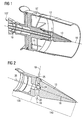
- Fig. 1 shows a burner 107 according to the invention.
- swirl blades 17 are arranged around the lance.
- the swirl blades 17 are arranged along the circumference of the lance in the housing 12.
- a compressor air flow 15 is passed into the leading to a combustion chamber part of the burner 107.
- the air is displaced by the swirl blades 17 in a swirling motion.
- the lance also comprises a fuel channel 16.
- the burner 107 further comprises an attachment 13 on the side leading to a combustion chamber.
- the attachment 13 can be welded to the lance, for example or screwed.
- the fuel nozzles are arranged in the attachment 13 preferably downstream of the swirl vanes 17 and are fluidically connected to the fuel channel 16, here represented as an oil channel.
- the fuel channel 16 here represented as an oil channel.
- eight such burners 107 are arranged in a circle (not shown).
- the burners 107 are arranged around a pilot burner (not shown) with pilot cone.
- the plurality of fuel nozzles according to the invention are designed as full jet nozzles 1.
- the design of the nozzle as a full jet nozzle 1, the full jet nozzle size and also arrangement make it possible to adjust the penetration depth of the fuel so that an advantageous fuel profile is formed.
- the parameters are the diameter of the full jet nozzles 1 and the number of full jet nozzles 1 available.
- the fuel distribution is adjusted so that the ignition of the fuel-air mixture is done with a beneficial time delay.
- the time delay between the injection and the combustion of the fuel is decisive for the formation of thermoacoustic feedback loops, from which combustion chamber pulsations can arise.
- the full jet nozzles 1 have a length, wherein the length to diameter ratio is at least 1.5, in order to achieve a good mixing. As a result, the divergence of the full jet is small enough, so that it does not come to an unwanted ejection of drops.
- the full-jet nozzle 1 has the advantage that a higher fuel pressure, especially in one greater penetration depth is implemented.
- a higher fuel pressure especially in one greater penetration depth is implemented.
- smaller drops are formed by a higher pre-pressure, which in turn are less effective to penetrate. It follows that a much higher pressure is required for an increased penetration depth for pressure-swirl nozzles than for full-jet nozzles. This can be with the full jet nozzle 1, for example, expensive pumps that can provide more fuel supply pressure, or avoid piping systems with high pressure levels.
- the Fig. 2 schematically shows a section through the attachment 13 in a perspective view.
- the center attachment axis of the attachment 13 is identified by the reference numeral 18.
- the attachment 13 is conical towards the combustion chamber, tapered designed. It comprises several, in the present embodiment four, full jet nozzles 1.
- the full jet nozzles 1 are arranged on the outer circumference of the attachment 13.
- the center axes of the full-jet nozzles 1 are identified by the reference numeral 19.
- the central axes 19 of the full-jet nozzles 1 have an angle 20 to the central attachment axis 18 of the attachment 13.
- the fuel enters the attachment 13 along the direction of flow indicated by the reference numeral 26 through the fuel channel 16.
- the fuel is then injected through the full jet nozzles 1 in the direction 25 in the coming of the swirl blades 17 air flow.
- the central axis 19 of the full-jet nozzles 1 is arranged substantially perpendicularly (90 degrees) to the middle attachment axis 18 of the full-jet nozzles 1.
- the central axis 19 of the nozzle 1 may be perpendicular to the attachment surface.
- the steel is introduced vertically into the air stream; a very good mix is the result.
- an arrangement of 90 ° +/- 30 ° degrees, in particular 90 ° +/- 10 ° degree, from the central axis 19 of the full-jet nozzles 1 to the axis 18 or the top surface results in a very advantageous arrangement.
- the attachment 13 comprises a cylindrical portion 130 and a tapered portion 140 to a combustion chamber.
- the conical portion 140 may have a cone angle of 10-20 ° degrees exhibit. Due to this configuration, there is no demolition of the flow at the attachment tip.
- the full-jet nozzles 1 can be arranged on the conical tapering part 140 of the attachment 13.
- the position of the full jet nozzles 1 may vary depending on the autoignition time of the mixture. In order to achieve a good fuel distribution, eight to twelve full-jet nozzles per attachment 13 are preferably used (not shown). Also advantageous are six to sixteen full jet nozzles 1 (not shown). These are evenly distributed on the circumference of the article 13. Good fuel distribution is necessary to meet emission limits and avoid soot formation.
- the full-jet nozzles 1 may be formed as bores in the attachment 13. In terms of mixing, in particular, a length to diameter ratio of six to fourteen is advantageous. Preferred diameter of the full-jet nozzles 1 are 0.55-0.8 mm, also 0.5 -1 mm are advantageous (not shown).
- solid jet nozzles 1 can easily be adapted to other thermodynamic conditions, which are e.g. in an altered air cross-flow speed, air density or fuel mass flow, perform by the diameter of the full jet nozzles 1 is adjusted accordingly.
Landscapes
- Engineering & Computer Science (AREA)
- Chemical & Material Sciences (AREA)
- Combustion & Propulsion (AREA)
- Mechanical Engineering (AREA)
- General Engineering & Computer Science (AREA)
- Nozzles For Spraying Of Liquid Fuel (AREA)
Priority Applications (5)
| Application Number | Priority Date | Filing Date | Title |
|---|---|---|---|
| EP10168107A EP2402652A1 (de) | 2010-07-01 | 2010-07-01 | Brenner |
| JP2013517313A JP6005040B2 (ja) | 2010-07-01 | 2011-07-01 | バーナー装置 |
| EP11728849.8A EP2588805B1 (de) | 2010-07-01 | 2011-07-01 | Brenneranordnung |
| PCT/EP2011/061101 WO2012001141A1 (de) | 2010-07-01 | 2011-07-01 | Brenneranordnung |
| US13/806,895 US20130104554A1 (en) | 2010-07-01 | 2011-07-01 | Burner assembly |
Applications Claiming Priority (1)
| Application Number | Priority Date | Filing Date | Title |
|---|---|---|---|
| EP10168107A EP2402652A1 (de) | 2010-07-01 | 2010-07-01 | Brenner |
Publications (1)
| Publication Number | Publication Date |
|---|---|
| EP2402652A1 true EP2402652A1 (de) | 2012-01-04 |
Family
ID=43531833
Family Applications (2)
| Application Number | Title | Priority Date | Filing Date |
|---|---|---|---|
| EP10168107A Withdrawn EP2402652A1 (de) | 2010-07-01 | 2010-07-01 | Brenner |
| EP11728849.8A Active EP2588805B1 (de) | 2010-07-01 | 2011-07-01 | Brenneranordnung |
Family Applications After (1)
| Application Number | Title | Priority Date | Filing Date |
|---|---|---|---|
| EP11728849.8A Active EP2588805B1 (de) | 2010-07-01 | 2011-07-01 | Brenneranordnung |
Country Status (4)
| Country | Link |
|---|---|
| US (1) | US20130104554A1 (enExample) |
| EP (2) | EP2402652A1 (enExample) |
| JP (1) | JP6005040B2 (enExample) |
| WO (1) | WO2012001141A1 (enExample) |
Cited By (3)
| Publication number | Priority date | Publication date | Assignee | Title |
|---|---|---|---|---|
| WO2017116266A1 (en) * | 2015-12-30 | 2017-07-06 | General Electric Company | Liquid fuel nozzles for dual fuel combustors |
| CN107023834A (zh) * | 2017-04-19 | 2017-08-08 | 中国科学院工程热物理研究所 | 一种多尺度值班火焰的喷嘴及燃烧器 |
| CN111520750A (zh) * | 2020-03-25 | 2020-08-11 | 西北工业大学 | 新型燃烧室头部喷油结构 |
Families Citing this family (25)
| Publication number | Priority date | Publication date | Assignee | Title |
|---|---|---|---|---|
| US9765973B2 (en) | 2013-03-12 | 2017-09-19 | General Electric Company | System and method for tube level air flow conditioning |
| US9650959B2 (en) | 2013-03-12 | 2017-05-16 | General Electric Company | Fuel-air mixing system with mixing chambers of various lengths for gas turbine system |
| US9651259B2 (en) | 2013-03-12 | 2017-05-16 | General Electric Company | Multi-injector micromixing system |
| US9534787B2 (en) | 2013-03-12 | 2017-01-03 | General Electric Company | Micromixing cap assembly |
| US9528444B2 (en) | 2013-03-12 | 2016-12-27 | General Electric Company | System having multi-tube fuel nozzle with floating arrangement of mixing tubes |
| US9759425B2 (en) * | 2013-03-12 | 2017-09-12 | General Electric Company | System and method having multi-tube fuel nozzle with multiple fuel injectors |
| US9671112B2 (en) | 2013-03-12 | 2017-06-06 | General Electric Company | Air diffuser for a head end of a combustor |
| JP5984770B2 (ja) * | 2013-09-27 | 2016-09-06 | 三菱日立パワーシステムズ株式会社 | ガスタービン燃焼器およびこれを備えたガスタービン機関 |
| CN106715870B (zh) | 2014-07-02 | 2018-11-09 | 诺沃皮尼奥内股份有限公司 | 燃料分配装置、燃气涡轮发动机和安装方法 |
| CN104315540B (zh) * | 2014-09-26 | 2018-05-25 | 北京华清燃气轮机与煤气化联合循环工程技术有限公司 | 燃气轮机燃烧室预混燃料喷嘴 |
| WO2016064391A1 (en) | 2014-10-23 | 2016-04-28 | Siemens Energy, Inc. | Flexible fuel combustion system for turbine engines |
| EP3224544A1 (en) * | 2014-11-26 | 2017-10-04 | Siemens Aktiengesellschaft | Fuel lance with means for interacting with a flow of air and improve breakage of an ejected liquid jet of fuel |
| US10738704B2 (en) * | 2016-10-03 | 2020-08-11 | Raytheon Technologies Corporation | Pilot/main fuel shifting in an axial staged combustor for a gas turbine engine |
| US10508811B2 (en) * | 2016-10-03 | 2019-12-17 | United Technologies Corporation | Circumferential fuel shifting and biasing in an axial staged combustor for a gas turbine engine |
| US10393030B2 (en) * | 2016-10-03 | 2019-08-27 | United Technologies Corporation | Pilot injector fuel shifting in an axial staged combustor for a gas turbine engine |
| US10739003B2 (en) | 2016-10-03 | 2020-08-11 | United Technologies Corporation | Radial fuel shifting and biasing in an axial staged combustor for a gas turbine engine |
| US10584877B2 (en) | 2017-04-28 | 2020-03-10 | DOOSAN Heavy Industries Construction Co., LTD | Device to correct flow non-uniformity within a combustion system |
| DE102020203422B4 (de) * | 2020-03-17 | 2024-02-01 | Dometic Sweden Ab | Heizvorrichtung, Freizeitfahrzeug mit Heizvorrichtung und Verfahren zum Heizen von Fluiden in einem Freizeitfahrzeug |
| US11421883B2 (en) * | 2020-09-11 | 2022-08-23 | Raytheon Technologies Corporation | Fuel injector assembly with a helical swirler passage for a turbine engine |
| US20220205637A1 (en) * | 2020-12-30 | 2022-06-30 | General Electric Company | Mitigating combustion dynamics using varying liquid fuel cartridges |
| KR102460672B1 (ko) * | 2021-01-06 | 2022-10-27 | 두산에너빌리티 주식회사 | 연료 노즐, 연료 노즐 모듈 및 이를 포함하는 연소기 |
| US12025311B2 (en) * | 2021-08-24 | 2024-07-02 | Solar Turbines Incorporated | Micromix fuel injection air nozzles |
| US11617981B1 (en) | 2022-01-03 | 2023-04-04 | Saudi Arabian Oil Company | Method for capturing CO2 with assisted vapor compression |
| KR102583223B1 (ko) * | 2022-01-28 | 2023-09-25 | 두산에너빌리티 주식회사 | 연소기용 노즐, 연소기 및 이를 포함하는 가스터빈 |
| GB2629434A (en) * | 2023-04-28 | 2024-10-30 | Siemens Energy Global Gmbh & Co Kg | Fuel lance for burner of gas turbine engine |
Citations (8)
| Publication number | Priority date | Publication date | Assignee | Title |
|---|---|---|---|---|
| US3904119A (en) * | 1973-12-05 | 1975-09-09 | Avco Corp | Air-fuel spray nozzle |
| US5680766A (en) * | 1996-01-02 | 1997-10-28 | General Electric Company | Dual fuel mixer for gas turbine combustor |
| JPH09303776A (ja) * | 1996-05-10 | 1997-11-28 | Mitsubishi Heavy Ind Ltd | ガスタービン燃焼器の燃料噴射ノズル |
| WO1999019670A2 (en) * | 1997-10-10 | 1999-04-22 | Siemens Westinghouse Power Corporation | FUEL NOZZLE ASSEMBLY FOR A LOW NOx COMBUSTOR |
| WO2000022347A1 (en) * | 1998-10-09 | 2000-04-20 | General Electric Company | Fuel injection assembly for gas turbine engine combustor |
| US6141967A (en) * | 1998-01-09 | 2000-11-07 | General Electric Company | Air fuel mixer for gas turbine combustor |
| EP1990580A1 (de) * | 2007-05-10 | 2008-11-12 | Siemens Aktiengesellschaft | Brennerkomponente für einen Gasturbinenbrenner |
| WO2010073156A1 (en) * | 2008-12-23 | 2010-07-01 | Tck - Societa' A Responsabilita' Limitata | A combustion head and a burner comprising the head |
Family Cites Families (14)
| Publication number | Priority date | Publication date | Assignee | Title |
|---|---|---|---|---|
| US5822992A (en) * | 1995-10-19 | 1998-10-20 | General Electric Company | Low emissions combustor premixer |
| JP3392633B2 (ja) * | 1996-05-15 | 2003-03-31 | 三菱重工業株式会社 | 燃焼器 |
| GB2324147B (en) * | 1997-04-10 | 2001-09-05 | Europ Gas Turbines Ltd | Fuel-injection arrangement for a gas turbine combuster |
| JP3443009B2 (ja) * | 1998-08-17 | 2003-09-02 | 三菱重工業株式会社 | 低NOx燃焼器 |
| JP2000310422A (ja) * | 1999-04-26 | 2000-11-07 | Mitsubishi Heavy Ind Ltd | 燃料ノズル |
| JP2000356344A (ja) * | 1999-06-14 | 2000-12-26 | Hitachi Ltd | ガスタービン燃焼装置及びその燃焼状態制御方法 |
| JP3860952B2 (ja) * | 2000-05-19 | 2006-12-20 | 三菱重工業株式会社 | ガスタービン燃焼器 |
| JP2002276943A (ja) * | 2001-03-14 | 2002-09-25 | Mitsubishi Heavy Ind Ltd | ガスタービン用燃料ノズル |
| US6832481B2 (en) * | 2002-09-26 | 2004-12-21 | Siemens Westinghouse Power Corporation | Turbine engine fuel nozzle |
| EP1507119A1 (de) * | 2003-08-13 | 2005-02-16 | Siemens Aktiengesellschaft | Brenner und Verfahren zum Betrieb einer Gasturbine |
| US7316117B2 (en) * | 2005-02-04 | 2008-01-08 | Siemens Power Generation, Inc. | Can-annular turbine combustors comprising swirler assembly and base plate arrangements, and combinations |
| RU2300702C1 (ru) * | 2006-04-04 | 2007-06-10 | Общество с ограниченной ответственностью "Научно-производственное предприятие "ЭСТ" | Способ сжигания топлива и устройство для его осуществления |
| JP4719059B2 (ja) * | 2006-04-14 | 2011-07-06 | 三菱重工業株式会社 | ガスタービンの予混合燃焼バーナー |
| EP2085695A1 (de) * | 2008-01-29 | 2009-08-05 | Siemens Aktiengesellschaft | Brennstoffdüse mit Drallkanal und Verfahren zur Herstellung einer Brennstoffdüse |
-
2010
- 2010-07-01 EP EP10168107A patent/EP2402652A1/de not_active Withdrawn
-
2011
- 2011-07-01 WO PCT/EP2011/061101 patent/WO2012001141A1/de not_active Ceased
- 2011-07-01 US US13/806,895 patent/US20130104554A1/en not_active Abandoned
- 2011-07-01 JP JP2013517313A patent/JP6005040B2/ja active Active
- 2011-07-01 EP EP11728849.8A patent/EP2588805B1/de active Active
Patent Citations (8)
| Publication number | Priority date | Publication date | Assignee | Title |
|---|---|---|---|---|
| US3904119A (en) * | 1973-12-05 | 1975-09-09 | Avco Corp | Air-fuel spray nozzle |
| US5680766A (en) * | 1996-01-02 | 1997-10-28 | General Electric Company | Dual fuel mixer for gas turbine combustor |
| JPH09303776A (ja) * | 1996-05-10 | 1997-11-28 | Mitsubishi Heavy Ind Ltd | ガスタービン燃焼器の燃料噴射ノズル |
| WO1999019670A2 (en) * | 1997-10-10 | 1999-04-22 | Siemens Westinghouse Power Corporation | FUEL NOZZLE ASSEMBLY FOR A LOW NOx COMBUSTOR |
| US6141967A (en) * | 1998-01-09 | 2000-11-07 | General Electric Company | Air fuel mixer for gas turbine combustor |
| WO2000022347A1 (en) * | 1998-10-09 | 2000-04-20 | General Electric Company | Fuel injection assembly for gas turbine engine combustor |
| EP1990580A1 (de) * | 2007-05-10 | 2008-11-12 | Siemens Aktiengesellschaft | Brennerkomponente für einen Gasturbinenbrenner |
| WO2010073156A1 (en) * | 2008-12-23 | 2010-07-01 | Tck - Societa' A Responsabilita' Limitata | A combustion head and a burner comprising the head |
Cited By (6)
| Publication number | Priority date | Publication date | Assignee | Title |
|---|---|---|---|---|
| WO2017116266A1 (en) * | 2015-12-30 | 2017-07-06 | General Electric Company | Liquid fuel nozzles for dual fuel combustors |
| US10830445B2 (en) | 2015-12-30 | 2020-11-10 | General Electric Company | Liquid fuel nozzles for dual fuel combustors |
| CN107023834A (zh) * | 2017-04-19 | 2017-08-08 | 中国科学院工程热物理研究所 | 一种多尺度值班火焰的喷嘴及燃烧器 |
| CN107023834B (zh) * | 2017-04-19 | 2019-01-08 | 中国科学院工程热物理研究所 | 一种多尺度值班火焰的喷嘴及燃烧器 |
| CN111520750A (zh) * | 2020-03-25 | 2020-08-11 | 西北工业大学 | 新型燃烧室头部喷油结构 |
| CN111520750B (zh) * | 2020-03-25 | 2022-05-20 | 西北工业大学 | 新型燃烧室头部喷油结构 |
Also Published As
| Publication number | Publication date |
|---|---|
| US20130104554A1 (en) | 2013-05-02 |
| EP2588805A1 (de) | 2013-05-08 |
| EP2588805B1 (de) | 2016-04-20 |
| JP6005040B2 (ja) | 2016-10-12 |
| JP2013529771A (ja) | 2013-07-22 |
| WO2012001141A1 (de) | 2012-01-05 |
Similar Documents
| Publication | Publication Date | Title |
|---|---|---|
| EP2402652A1 (de) | Brenner | |
| DE3029095C2 (de) | Doppelbrennstoffinjektor für ein Gasturbinentriebwerk | |
| EP2156095B1 (de) | Drallfreie stabilisierung der flamme eines vormischbrenners | |
| DE2143012A1 (de) | Brennersysteme | |
| DE102010017778A1 (de) | Vorrichtung zur Brennstoffeinspritzung bei einer Turbine | |
| EP2161502A1 (de) | Vormischbrenner zur Verbrennung eines niederkalorischen sowie hochkalorischen Brennstoffes | |
| DE112014001594T5 (de) | Brennkammer und Gasturbine | |
| EP2390491B1 (de) | Vorrichtung zum Einspritzen von Brennstoff in einen Brennraum | |
| EP2601447A2 (de) | Gasturbinenbrennkammer | |
| EP2609368A1 (de) | Brenneranordnung | |
| DE102016118633B4 (de) | Brennerkopf, Brennersystem und Verwendung des Brennersystems | |
| EP0911582B1 (de) | Verfahren zum Betrieb eines Vormischbrenners und Vormischbrenner | |
| EP2171354B1 (de) | Brenner | |
| DE102006051286A1 (de) | Brennervorrichtung | |
| EP2558781B1 (de) | Drallerzeuger für einen brenner | |
| EP4089325B1 (de) | Düse zum einblasen von gas in eine verbrennungsanlage mit einem rohr und einem drallerzeuger, rauchgaszug mit einer derartigen düse und verfahren zur verwendung einer derartigen düse | |
| DE102017118166B4 (de) | Brennerkopf, Brennersystem und Verwendung des Brennersystems | |
| DE2932378A1 (de) | Brennkammer fuer gasturbinentriebwerke | |
| DE102004006665A1 (de) | Einspritzelement in Koaxialbauweise mit zwei Brennzonen | |
| EP2310741B1 (de) | Brennstoffeinsatz | |
| DE102021123513A1 (de) | Brenner und Verfahren zu dessen Herstellung | |
| WO2015158489A1 (de) | Brenner mit drallschaufel | |
| WO2011022847A1 (de) | Brenner zur erzeugung eines heissgasstromes | |
| EP2407715A1 (de) | Brenner | |
| WO2011022846A1 (de) | Ölbrenner, insbesondere für schweröl |
Legal Events
| Date | Code | Title | Description |
|---|---|---|---|
| AK | Designated contracting states |
Kind code of ref document: A1 Designated state(s): AL AT BE BG CH CY CZ DE DK EE ES FI FR GB GR HR HU IE IS IT LI LT LU LV MC MK MT NL NO PL PT RO SE SI SK SM TR |
|
| AX | Request for extension of the european patent |
Extension state: BA ME RS |
|
| PUAI | Public reference made under article 153(3) epc to a published international application that has entered the european phase |
Free format text: ORIGINAL CODE: 0009012 |
|
| STAA | Information on the status of an ep patent application or granted ep patent |
Free format text: STATUS: THE APPLICATION IS DEEMED TO BE WITHDRAWN |
|
| 18D | Application deemed to be withdrawn |
Effective date: 20120705 |