EP2402567A1 - Système de purge de gaz inertes pour chaudière de récupération de chaleur ORC - Google Patents
Système de purge de gaz inertes pour chaudière de récupération de chaleur ORC Download PDFInfo
- Publication number
- EP2402567A1 EP2402567A1 EP20110171995 EP11171995A EP2402567A1 EP 2402567 A1 EP2402567 A1 EP 2402567A1 EP 20110171995 EP20110171995 EP 20110171995 EP 11171995 A EP11171995 A EP 11171995A EP 2402567 A1 EP2402567 A1 EP 2402567A1
- Authority
- EP
- European Patent Office
- Prior art keywords
- interior volume
- heat recovery
- inert gas
- leak
- recovery boiler
- Prior art date
- Legal status (The legal status is an assumption and is not a legal conclusion. Google has not performed a legal analysis and makes no representation as to the accuracy of the status listed.)
- Granted
Links
Images


Classifications
-
- F—MECHANICAL ENGINEERING; LIGHTING; HEATING; WEAPONS; BLASTING
- F22—STEAM GENERATION
- F22B—METHODS OF STEAM GENERATION; STEAM BOILERS
- F22B33/00—Steam-generation plants, e.g. comprising steam boilers of different types in mutual association
- F22B33/18—Combinations of steam boilers with other apparatus
-
- F—MECHANICAL ENGINEERING; LIGHTING; HEATING; WEAPONS; BLASTING
- F01—MACHINES OR ENGINES IN GENERAL; ENGINE PLANTS IN GENERAL; STEAM ENGINES
- F01K—STEAM ENGINE PLANTS; STEAM ACCUMULATORS; ENGINE PLANTS NOT OTHERWISE PROVIDED FOR; ENGINES USING SPECIAL WORKING FLUIDS OR CYCLES
- F01K25/00—Plants or engines characterised by use of special working fluids, not otherwise provided for; Plants operating in closed cycles and not otherwise provided for
- F01K25/08—Plants or engines characterised by use of special working fluids, not otherwise provided for; Plants operating in closed cycles and not otherwise provided for using special vapours
- F01K25/10—Plants or engines characterised by use of special working fluids, not otherwise provided for; Plants operating in closed cycles and not otherwise provided for using special vapours the vapours being cold, e.g. ammonia, carbon dioxide, ether
-
- F—MECHANICAL ENGINEERING; LIGHTING; HEATING; WEAPONS; BLASTING
- F01—MACHINES OR ENGINES IN GENERAL; ENGINE PLANTS IN GENERAL; STEAM ENGINES
- F01K—STEAM ENGINE PLANTS; STEAM ACCUMULATORS; ENGINE PLANTS NOT OTHERWISE PROVIDED FOR; ENGINES USING SPECIAL WORKING FLUIDS OR CYCLES
- F01K23/00—Plants characterised by more than one engine delivering power external to the plant, the engines being driven by different fluids
- F01K23/02—Plants characterised by more than one engine delivering power external to the plant, the engines being driven by different fluids the engine cycles being thermally coupled
- F01K23/06—Plants characterised by more than one engine delivering power external to the plant, the engines being driven by different fluids the engine cycles being thermally coupled combustion heat from one cycle heating the fluid in another cycle
- F01K23/10—Plants characterised by more than one engine delivering power external to the plant, the engines being driven by different fluids the engine cycles being thermally coupled combustion heat from one cycle heating the fluid in another cycle with exhaust fluid of one cycle heating the fluid in another cycle
-
- F—MECHANICAL ENGINEERING; LIGHTING; HEATING; WEAPONS; BLASTING
- F01—MACHINES OR ENGINES IN GENERAL; ENGINE PLANTS IN GENERAL; STEAM ENGINES
- F01N—GAS-FLOW SILENCERS OR EXHAUST APPARATUS FOR MACHINES OR ENGINES IN GENERAL; GAS-FLOW SILENCERS OR EXHAUST APPARATUS FOR INTERNAL COMBUSTION ENGINES
- F01N5/00—Exhaust or silencing apparatus combined or associated with devices profiting from exhaust energy
- F01N5/02—Exhaust or silencing apparatus combined or associated with devices profiting from exhaust energy the devices using heat
-
- F—MECHANICAL ENGINEERING; LIGHTING; HEATING; WEAPONS; BLASTING
- F02—COMBUSTION ENGINES; HOT-GAS OR COMBUSTION-PRODUCT ENGINE PLANTS
- F02C—GAS-TURBINE PLANTS; AIR INTAKES FOR JET-PROPULSION PLANTS; CONTROLLING FUEL SUPPLY IN AIR-BREATHING JET-PROPULSION PLANTS
- F02C6/00—Plural gas-turbine plants; Combinations of gas-turbine plants with other apparatus; Adaptations of gas- turbine plants for special use
- F02C6/18—Plural gas-turbine plants; Combinations of gas-turbine plants with other apparatus; Adaptations of gas- turbine plants for special use using the waste heat of gas-turbine plants outside the plants themselves, e.g. gas-turbine power heat plants
-
- F—MECHANICAL ENGINEERING; LIGHTING; HEATING; WEAPONS; BLASTING
- F02—COMBUSTION ENGINES; HOT-GAS OR COMBUSTION-PRODUCT ENGINE PLANTS
- F02G—HOT GAS OR COMBUSTION-PRODUCT POSITIVE-DISPLACEMENT ENGINE PLANTS; USE OF WASTE HEAT OF COMBUSTION ENGINES; NOT OTHERWISE PROVIDED FOR
- F02G5/00—Profiting from waste heat of combustion engines, not otherwise provided for
- F02G5/02—Profiting from waste heat of exhaust gases
-
- F—MECHANICAL ENGINEERING; LIGHTING; HEATING; WEAPONS; BLASTING
- F22—STEAM GENERATION
- F22B—METHODS OF STEAM GENERATION; STEAM BOILERS
- F22B1/00—Methods of steam generation characterised by form of heating method
- F22B1/02—Methods of steam generation characterised by form of heating method by exploitation of the heat content of hot heat carriers
- F22B1/18—Methods of steam generation characterised by form of heating method by exploitation of the heat content of hot heat carriers the heat carrier being a hot gas, e.g. waste gas such as exhaust gas of internal-combustion engines
- F22B1/1807—Methods of steam generation characterised by form of heating method by exploitation of the heat content of hot heat carriers the heat carrier being a hot gas, e.g. waste gas such as exhaust gas of internal-combustion engines using the exhaust gases of combustion engines
- F22B1/1815—Methods of steam generation characterised by form of heating method by exploitation of the heat content of hot heat carriers the heat carrier being a hot gas, e.g. waste gas such as exhaust gas of internal-combustion engines using the exhaust gases of combustion engines using the exhaust gases of gas-turbines
-
- F—MECHANICAL ENGINEERING; LIGHTING; HEATING; WEAPONS; BLASTING
- F22—STEAM GENERATION
- F22B—METHODS OF STEAM GENERATION; STEAM BOILERS
- F22B35/00—Control systems for steam boilers
- F22B35/001—Controlling by flue gas dampers
-
- F—MECHANICAL ENGINEERING; LIGHTING; HEATING; WEAPONS; BLASTING
- F22—STEAM GENERATION
- F22B—METHODS OF STEAM GENERATION; STEAM BOILERS
- F22B37/00—Component parts or details of steam boilers
- F22B37/02—Component parts or details of steam boilers applicable to more than one kind or type of steam boiler
- F22B37/42—Applications, arrangements, or dispositions of alarm or automatic safety devices
- F22B37/421—Arrangements for detecting leaks
-
- Y—GENERAL TAGGING OF NEW TECHNOLOGICAL DEVELOPMENTS; GENERAL TAGGING OF CROSS-SECTIONAL TECHNOLOGIES SPANNING OVER SEVERAL SECTIONS OF THE IPC; TECHNICAL SUBJECTS COVERED BY FORMER USPC CROSS-REFERENCE ART COLLECTIONS [XRACs] AND DIGESTS
- Y02—TECHNOLOGIES OR APPLICATIONS FOR MITIGATION OR ADAPTATION AGAINST CLIMATE CHANGE
- Y02P—CLIMATE CHANGE MITIGATION TECHNOLOGIES IN THE PRODUCTION OR PROCESSING OF GOODS
- Y02P80/00—Climate change mitigation technologies for sector-wide applications
- Y02P80/10—Efficient use of energy, e.g. using compressed air or pressurized fluid as energy carrier
- Y02P80/15—On-site combined power, heat or cool generation or distribution, e.g. combined heat and power [CHP] supply
Definitions
- the subject matter disclosed herein relates to waste heat recovery systems employing boilers, and more specifically, to inert gas purging systems for heat recovery boilers.
- Waste heat recovery systems may be employed to recover low-grade heat, such as heat with a temperature below approximately 500°C, from industrial and commercial processes and operations.
- waste heat recovery systems may be employed to recover low-grade heat from hot exhaust gases produced by gas turbines.
- Waste heat recovery systems that implement an Organic Rankine Cycle (ORC) by circulating an organic working fluid may be particularly efficient at recovering low-grade heat due to the relatively low phase change enthalpies of organic working fluids.
- ORC Organic Rankine Cycle
- a system in a first embodiment, includes a valve system switchable between a waste heat recovery position configured to direct incoming exhaust gas through an interior volume of an exhaust section of an engine and a bypass position configured to direct the incoming exhaust gas through a bypass duct to bypass a heat recovery boiler disposed within the interior volume.
- the system also includes an inert gas purging system configured to inject an inert gas into the interior volume to displace residual exhaust gas from the interior volume.
- a system in a second embodiment, includes a heat recovery boiler configured to absorb heat directly from exhaust gas within an exhaust section of an engine to heat an organic working fluid within the heat recovery boiler, an expander configured to expand the heated organic working fluid, a condenser configured to condense the expanded organic working fluid, a pump configured to direct the condensed organic working fluid to the heat recovery boiler, a sensor configured to detect a leak of the organic working fluid from the heat recovery boiler, and an inert gas purging system configured to inject inert gas into the exhaust section in response to detection of the leak.
- a method in a third embodiment, includes detecting a leak of an organic working fluid from a heat recovery boiler into an interior volume of an exhaust section of an engine, setting a valve to a bypass position to direct incoming exhaust gas to bypass the interior volume of the exhaust section in response to detecting the leak, and injecting an inert gas into the interior volume to displace residual exhaust gas from the interior volume in response to detecting the leak.
- the present disclosure is directed to waste heat recovery systems that employ inert gas purging systems for heat recovery boilers.
- the waste heat recovery systems may recover low-grade heat from a system, such as a gas turbine, by implementing an Organic Rankine Cycle (ORC) with an organic working fluid, such as a hydrocarbon fluid or refrigerant.
- ORC Organic Rankine Cycle
- the present systems may employ a "direct" heat recovery boiler that transfers heat directly from the gas turbine exhaust gas to the working fluid.
- the heat recovery boiler which circulates the working fluid, may be disposed directly in the path of the exhaust gas within the exhaust section of the gas turbine. Placing the heat recovery boiler directly in the path of the exhaust gas, rather than using a secondary loop to transfer heat between the exhaust gas and the waste heat recovery system, may increase the overall efficiency of the waste heat recovery system, as well as reducing capital and/or operational costs.
- the power generation system may employ a purging system for the heat recovery boiler.
- the purging system may be enabled upon detection of a leak in the heat recovery boiler.
- the purging system may redirect the flow of exhaust gases so that the exhaust gases bypass the heat recovery boiler.
- the purging system may inject an inert gas into the exhaust gas duct to purge residual exhaust gases from the exhaust duct.
- the inert gas also may cool the heat recovery boiler and dilute any leaking fluid, thereby extinguishing and/or inhibiting flames within the exhaust duct.
- FIG. 1 depicts an embodiment of a power generation system 10 that may employ a heat recovery boiler purging system.
- the power generation system 10 includes an engine, such as a gas turbine engine 12, that generates waste heat that may be recovered by a waste heat recovery system 16.
- the gas turbine engine 12 is provided as one example of an engine that produces waste heat, and is not intended to be limiting.
- the waste heat recovery system described herein may be employed to recover heat from other types of engines that generate waste heat.
- the waste heat recovery system 16 may recover heat from a reciprocating engine, or other suitable engine that produces waste heat.
- the gas turbine engine 12 combusts fuel (e.g. a liquid or gas fuel) to drive a first load 14.
- the power generation system 10 also includes a waste heat recovery system 16 that recovers low-grade heat from the gas turbine to drive a second load 18.
- the first and second loads 14 and 18 may be electrical generators for generating electrical power.
- the types of loads driven by the power generation system 10 may vary.
- the gas turbine engine 12 includes an air intake section 20, a compressor 22, a combustor section 24, a turbine 26, and an exhaust section 28.
- the turbine 26 is coupled to the compressor 22 via a shaft 30.
- Air 32 may enter the gas turbine engine 12 through the intake section 20 and flow into the compressor 22 where the air may be compressed to provide compressed air 34 to the combustor section 24.
- the compressed air 34 may mix with fuel in a fuel-to-air ratio that facilitates combustion of the fuel to produce combustion gases 36.
- the combustor section 24 may include multiple combustors disposed annularly around the shaft 30.
- the hot combustion gases 36 may flow through the turbine 26 to drive the compressor 22 and/or the first load 14 via the shaft 30.
- the combustion gases 36 may apply motive forces to turbine rotor blades within the turbine 26 to rotate the shaft 30.
- the hot combustion gases may exit the gas turbine engine 12 as exhaust gases 38 that flow through the exhaust section 28 to exit the gas turbine engine 12.
- the exhaust gases 38 may flow through an heat recovery boiler 40 that may absorb heat from the exhaust gases 38 to produce cooled exhaust gases 42.
- the heat recovery boiler 40 is located directly in the flow path of the exhaust gases 38 so that the exhaust gases 38 may transfer heat directly to a working fluid flowing through the heat recovery boiler 40.
- the cooled exhaust gases 42 may then exit the exhaust section 28 and may be directed through ductwork 43 to a stack 44 where the gases may be vented to the atmosphere.
- the exhaust section 28 also may include a bypass duct 46 that allows the exhaust gases 38 to exit the exhaust section 28 without flowing past the heat recovery boiler 40.
- the bypass duct 46 may be employed to remove exhaust gases 38 from the exhaust section 28 if the heat recovery boiler 40 develops a leak that may expose combustible organic working fluid from the heat recovery boiler 40 to the exhaust gases 38.
- the exhaust gases 38 may be directed through the bypass duct 46 to exit the exhaust section 28 as bypass exhaust gases 48 that have bypassed the heat recovery boiler 40.
- the bypass exhaust gases 48 may be directed to the stack 44 where the gases may be vented to the atmosphere. As shown, both the bypass exhaust gases 48 and the cooled exhaust gases 42 may be directed to the same stack 44. However, in other embodiments, the bypass exhaust gases 48 and the cooled exhaust gases 42 may be directed to separate stacks.
- the hot exhaust gases 38 may transfer heat to a working fluid flowing through the heat recovery boiler 40 within a working fluid loop 50.
- the heat recovery boiler 40 may be a fin and tube heat exchanger that allows the working fluid to be circulated within the working fluid loop 50 directly in the path of the exhaust gases 38. Accordingly, the exhaust gases 38 may transfer heat directly to the working fluid circulating within the waste heat recovery system 16, rather than transferring heat through an intermediate loop, such as an oil loop.
- the waste heat recovery system 16 may circulate an organic working fluid within the working fluid loop 50 to recover waste heat from the exhaust gases 38.
- Any suitable organic working fluid such as a hydrocarbon fluid or refrigerant, may be employed.
- the use of an organic working fluid may be particularly well suited to the waste heat recovery loop 50 due to the relatively low phase change enthalpy of the organic working fluid.
- the organic working fluid may be an organic, high molecular mass, fluid that has a higher vapor pressure and lower critical temperature than water.
- the working fluid may absorb heat from the exhaust gases 38 causing all, or a substantial portion of the working fluid to change from a liquid phase to a vapor phase.
- the heated working fluid may then flow to an expander generator set 52 where the working fluid may be expanded to drive the second load 18.
- the expander generator set 52 may include an expander that may be coupled to a generator to produce electricity from the expansion of the heated working fluid.
- the working fluid may flow to a condenser 54 where the working fluid may be condensed.
- the condenser 54 may be an air-cooled heat exchanger. However, in other embodiments, any suitable type of condenser may be employed.
- the condensed working fluid may then flow through a pump 58 that returns the working fluid to the heat recovery boiler 40 where the process may begin again.
- additional equipment such as valves, temperature and/or pressure sensors or transducers, receivers, and the like, may be included in the waste heat recovery system 16.
- a recuperator or preheater may be included upstream from the heat recovery boiler 40 to preheat the working fluid before it enters the heat recovery boiler 40.
- the waste heat recovery system 16 may be installed as part of a new power generation system 10 and/or may be retrofit into an existing power generation system 10.
- an existing gas turbine 12 may be retrofitted with a waste heat recovery system 16 that disposes a heat recovery boiler 40 in the exhaust gas section 28.
- the heat recovery boiler 40 is located within the exhaust section 28 directly in the flow path of the hot exhaust gas 38.
- the direct transfer of heat from the exhaust gas to the waste heat recovery system 16 may increase the overall efficiency of the waste heat recovery system 16 when compared to a system using an intermediate loop to indirectly transfer heat from the exhaust gas to the waste heat recovery system. Further, the elimination of a secondary loop may reduce capital and/or operational costs.
- FIGS. 2 and 3 depict an inert gas purging system that may be employed to remove and/or to dilute exhaust gases 38 from the exhaust section 28.
- the exhaust gases 38 may flow through an opening 58 to enter an interior volume 60 of the exhaust section 28, as generally shown by arrows 61.
- the heat recovery boiler 40 may be located within the interior volume 60 in the flow path of the exhaust gases 38.
- the heat recovery boiler 40 includes finned tubes 62 in which the working fluid is circulated. According to certain embodiments, the finned tubes 62 may be disposed generally perpendicular to the flow of the exhaust gas 38 through the interior volume 60 to promote good heat transfer from the exhaust gases 38 to the working fluid circulating within the finned tubes 62.
- the cooled exhaust gases 42 may exit the exhaust section 28 and enter the stack 44 through an inlet 63.
- the working fluid circulating within the finned tubes 62 may be potentially flammable, it may be desirable to remove the exhaust gases 38 from the interior volume 60 in the event of a leak in the finned tubes 62. Accordingly, in the event of a leak, rather than directing the exhaust gases 38 through the opening 58 to the interior volume 60, the exhaust gases 38 may be directed through an opening 64 to flow through the bypass duct 46, as shown generally by arrows 65 in FIG. 3 .
- valves 66 may be employed, which are switchable between a waste heat recovery position as shown in FIG. 2 and a bypass position as shown in FIG. 3 .
- the valves 66 may include any type of flow directing, switching, and/or throttling devices that may be switched between positions to permit flow in one position and to restrict flow in another position.
- the valves 66 may include baffles or dampers; however, in other embodiments, any suitable type of valves may be employed.
- the valve 66 may be positioned to direct the exhaust gases 38 through the interior volume 60, as shown in FIG. 2 .
- the valve 66 In the bypass position, the valve 66 may be positioned to direct the exhaust gases 38 through the bypass duct 46, as shown in FIG. 3 .
- the valve 66 is shown in FIGS. 2 and 3 as a single baffle, in other embodiments, a system of two or more baffles and/or dampers may be employed to switch the flow of the exhaust gases between the interior volume 60 and the bypass duct 46.
- the valve 66 is positioned over the opening 64 to allow the exhaust gases 38 to flow through the opening 58 into the interior volume 60 where the exhaust gases 38 may flow through the heat recovery boiler 40.
- a flap 69 may be opened within inlet 63 to allow exhaust gases to flow from the interior volume 60 into the stack 44 through the inlet 63.
- a flap 71 may be closed within the bypass duct 46 to impede the flow of exhaust gases into the bypass duct 46 from the stack 44.
- the flaps 69 and 71 may be positioned within the ductwork 43, within the stack inlets 63 and 67, or within the bypass duct 46 and the exhaust section 28. Further, in certain embodiments, the flaps 69 and 71 may be omitted.
- the valve 66 When the bypass mode is enabled as shown in FIG. 3 , the valve 66 may be positioned over opening 58 to allow the exhaust gases 38 to flow through the opening 64 into the bypass duct 46. Accordingly, in the bypass mode, the exhaust gases 38 may bypass the heat recovery boiler 40 by flowing through the bypass duct 48 and into the stack 44 through an inlet 67. In the bypass mode, the flap 71 may be opened to allow the exhaust gases to flow from the bypass duct 46 to the stack 44 through inlet 67. Further, the flap 69 may be closed to impede the flow of exhaust gases from the stack 44 into the interior volume 60 through the inlet 63.
- the bypass duct 46 may be employed when a leak is detected in the finned tubes 62 of the heat recovery boiler 40.
- one or more sensors 68 may be employed to detect a leak in the finned tubes 62.
- the sensor 68 may measure the level of hydrocarbons in the exhaust gas exiting the interior volume 60. An increased level of hydrocarbons may indicate a leak within the finned tubes 62.
- the sensor 68 may be designed to detect presence of a flame in or around the heat recovery boiler 40, such as by measuring ultraviolet light. The presence of a flame may indicate a leak within the finned tubes 62.
- multiple sensors 68 such as multiple hydrocarbon sensors, multiple flame detection sensors, or combinations thereof, may be employed.
- the sensor 68 may be designed to measure other parameters indicative of the composition of the exhaust gases 38.
- the sensor 68 may be located in the inlet 63 to the stack 44. However, in other embodiments, the sensor 68 may be positioned within the interior volume 60.
- the sensor 68 may be communicatively coupled to a controller 70 that may be used to change the position of the valve 66.
- the controller 70 may receive an input, such as a hydrocarbon level, from the sensor 68 that indicates that a leak is present in the finned tubes 62.
- the controller 70 may send a control signal to the valve 66 to move the valve to close opening 58, as shown in FIG. 3 , thereby directing the exhaust gases 38 through the opening 64 and into the bypass duct 46.
- the controller 70 may include an analog to digital (A/D) converter, a microprocessor, a non-volatile memory, and an interface board, among components.
- A/D analog to digital
- valve 66 may be mechanically and/or manually controlled.
- the controller 70 may produce an output, such as an alarm, that indicates that the valve 66 should be moved, for example by an operator, to close the opening 58.
- the controller 70 also may govern operation of an inert gas injection system 72 that may be used to purge residual exhaust gases 38 from the interior volume 60 after the valve 66 has been moved to the bypass position.
- the inert gas injection system 72 may include an inert gas supply 74, such as one or more high pressure gas cylinders, which supplies inert gases for the inert gas injection system 72.
- the term "inert gases” shall mean any gas or mixture of gases suitable to suppress combustion, prevent explosion, or extinguish a flame, primarily by dilution and/or displacement of oxygen in the exhaust gas.
- the inert gases may include nitrogen and/or carbon dioxide.
- Piping 76 may be used to direct the inert gases from the inert gas supply 74 into the interior volume 60.
- a valve 78 may be included within the piping 76 to regulate the flow of the inert gases from the tank 74 into the interior volume 60.
- the valve 78 may be closed when the system is operating in a waste heat recovery mode to prevent the inert gases from entering the interior volume 60 and may be opened to allow the inert gases to enter the interior volume 60 when the system is operating in the bypass mode.
- the valve 78 may be employed to increase and decrease the flow rate of the inert gases into the interior volume 60.
- a system of multiple valves 78 may be included within the piping 76.
- the controller 70 may govern the operation of the inert gas injection system 72 through the valve 78. According to certain embodiments, the controller 70 may open the valve 78 in response to detecting a leak to allow the inert gases to enter the interior volume 60.
- the inert gases may enter the interior volume through one or more nozzles 79 that may inject the inert gases into the interior volume 60 from the piping 76.
- the nozzles 79 may allow the inert gases to be injected into the interior volume 60 at relatively high flow rates. Further, the nozzles 79 may be located along the top, bottom, and/or sides, as well as around the exhaust gas inlet area, of the interior volume 60.
- the inert gases may displace residual exhaust gases 38 within the interior volume 60 causing the residual exhaust gases to exit the interior volume 60 and enter the stack 44 through the inlet 63. Accordingly, when bypass mode is enabled, the flap 69 may remain open for a certain period of time to allow the residual exhaust gases to exit the interior volume 60 through the inlet 63. After the residual exhaust gases have exited the interior volume 60, the flap 69 may be closed, as shown in FIG. 3 , to inhibit flow of exhaust gases from the stack 44 into the interior volume 60 through the inlet 63.
- the inert gases also may cool the finned tubes 62 and the interior volume 60, thereby lowering the pressure and temperature in within the interior volume 60. Further, the inert gases may dilute oxygen and hydrocarbon vapors within the interior volume 60, thereby extinguishing any flames that are present within the interior volume 60 and/or inhibiting flames and/or explosion within the exhaust section 28.
- valve 78 After valve 78 has been opened to allow the inert gases to enter the interior volume 60, the controller 70 may stop operation of the pump 58 that circulates the working fluid through the heat recovery boiler 40.
- the working fluid may evaporate from the heat recovery boiler 40 and collect within the working fluid loop 50. Accordingly, additional working fluid may be inhibited from leaking into the interior volume 60 through the heat recovery boiler 40.
- FIG. 3 depicts the exhaust section 28 when the system is in the bypass mode to direct the exhaust gases 38 through the bypass duct 46.
- the valve 66 is positioned over the opening 58 to close the opening 58 and allow the exhaust gases 38 to flow through the opening 64 the bypass duct 46. Accordingly, incoming exhaust gases 38 will be directed to the bypass duct 46 rather than to the interior volume 60 that houses the heat recovery boiler 40.
- a single valve 66 may be moved to close off opening 58 and allow flow through the opening 64.
- a system of multiple valves 66 such as multiple baffles or dampers, among others, may be employed to switch the system between a waste heat recovery mode where the exhaust gases enter the interior volume 60 and a bypass mode where the exhaust gases enter the bypass duct 46.
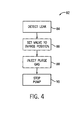
- FIG. 4 is a flowchart depicting a method 82 that may be used to purge the interior volume 60 of exhaust gases 38.
- the method 82 may begin by detecting (block 84) a leak in the heat recovery boiler 40.
- a sensor 68 may detect increased levels of hydrocarbons and/or the presence of a flame.
- the sensor 68 may provide a signal indicating the level of hydrocarbons to the controller 70 ( FIG. 2 ).
- the controller 70 may then compare the level to a predetermined threshold or rate of change to determine if a leak is present.
- the sensor 68 may determine whether a leak is present and may provide a control input indicating a leak to the controller 70.
- the controller 70 may set (block 86) the valve to the bypass position. For example, as shown in FIG. 3 , the controller 70 may switch the valve to close off opening 58 and direct the exhaust gases 38 into the bypass duct 46 through the opening 64. In another embodiment, two or more baffles may be used, and in these embodiments, the controller 70 may move one baffle to close the opening 58 and may move another baffle to open the opening 64.
- the controller 70 may inject (block 88) purge gas into the interior volume 60.
- the controller 70 may activate the inert gas purging system by opening valve 78 to allow the inert gases to flow into the interior volume 60 through the nozzles 79.
- the inert gases may then purge residual exhaust gases 38 from the interior volume 60 by displacing the residual exhaust gases 38 from the interior volume 60 to the stack 44 through the inlet 63.
- the inert gases also may reduce the temperature within the interior volume 60, thereby reducing the occurrence of fire and/or extinguishing any flames that may be present within the interior volume 60.
- the controller 70 also may stop (block 90) operation of the pump 56 ( FIG. 1 ) that circulates the working fluid through the heat recovery boiler 62. Stopping the pump may inhibit additional working fluid from entering the interior volume 60 through the heat recovery boiler 40.
- repairs may be conducted to repair any leaks within the heat recovery boiler 40.
- the finned tubes 62 may be repaired or replaced.
- the valve 66 may be reset to the waste heat recovery position, as shown in FIG. 2 , which allows the incoming exhaust gases 38 to again enter the interior volume 60.
Applications Claiming Priority (1)
| Application Number | Priority Date | Filing Date | Title |
|---|---|---|---|
| US12/827,105 US20120000200A1 (en) | 2010-06-30 | 2010-06-30 | Inert gas purging system for an orc heat recovery boiler |
Publications (2)
| Publication Number | Publication Date |
|---|---|
| EP2402567A1 true EP2402567A1 (fr) | 2012-01-04 |
| EP2402567B1 EP2402567B1 (fr) | 2015-09-30 |
Family
ID=44582146
Family Applications (1)
| Application Number | Title | Priority Date | Filing Date |
|---|---|---|---|
| EP11171995.1A Active EP2402567B1 (fr) | 2010-06-30 | 2011-06-29 | Système de purge de gaz inertes pour chaudière de récupération de chaleur ORC |
Country Status (8)
| Country | Link |
|---|---|
| US (1) | US20120000200A1 (fr) |
| EP (1) | EP2402567B1 (fr) |
| JP (1) | JP5856768B2 (fr) |
| KR (1) | KR101795041B1 (fr) |
| CN (1) | CN102383936B (fr) |
| CA (1) | CA2743517C (fr) |
| IL (1) | IL213658A0 (fr) |
| RU (1) | RU2578549C2 (fr) |
Cited By (4)
| Publication number | Priority date | Publication date | Assignee | Title |
|---|---|---|---|---|
| DE102012218621A1 (de) * | 2012-10-12 | 2014-04-17 | Robert Bosch Gmbh | Sicherheitsvorrichtung für eine Energieerzeugungsanlage und Verfahren zum Betrieb derselben |
| EP3037631A1 (fr) * | 2014-12-25 | 2016-06-29 | Panasonic Intellectual Property Management Co., Ltd. | Générateur d'énergie électrique thermique |
| EP3073096A1 (fr) * | 2015-03-25 | 2016-09-28 | Mitsubishi Hitachi Power Systems, Ltd. | Système de turbine à air humide et système de traitement de gaz d'échappement |
| AU2020101347B4 (en) * | 2020-07-13 | 2021-03-18 | Volt Power Group Limited | A waste heat recovery system |
Families Citing this family (14)
| Publication number | Priority date | Publication date | Assignee | Title |
|---|---|---|---|---|
| US9322300B2 (en) * | 2012-07-24 | 2016-04-26 | Access Energy Llc | Thermal cycle energy and pumping recovery system |
| US9540961B2 (en) * | 2013-04-25 | 2017-01-10 | Access Energy Llc | Heat sources for thermal cycles |
| GB2515330B (en) * | 2013-06-20 | 2015-11-04 | Boustead Internat Heaters Ltd | Improvements in waste heat recovery units |
| US9683515B2 (en) | 2013-07-02 | 2017-06-20 | Cummins, Inc. | Waste heat recovery system including a mechanism for collection, detection and removal of non-condensable gas |
| KR101947208B1 (ko) * | 2014-11-28 | 2019-02-12 | 현대중공업 주식회사 | 열 회수 보일러의 배기가스 바이패스 흐름 전환용 무선 제어 도어 장치 |
| AU2016353483A1 (en) * | 2015-11-13 | 2018-05-17 | Shell Internationale Research Maatschappij B.V. | Method of generating power using a combined cycle |
| KR101767250B1 (ko) * | 2016-12-12 | 2017-08-14 | 김준영 | 유기성 연료를 이용한 연소 발전 장치 |
| EP3555432A4 (fr) * | 2016-12-13 | 2020-08-12 | Blue Box Technology Inc. | Appareil pour extraire de l'énergie à partir de la chaleur perdue |
| KR20200104330A (ko) * | 2017-12-22 | 2020-09-03 | 지오바니 다′리엔조 | 보일러용 열병합 발전 시스템 |
| JP6634118B2 (ja) * | 2018-06-19 | 2020-01-22 | 株式会社神鋼環境ソリューション | 熱利用システム及び熱利用システムの運転方法 |
| CN108661733B (zh) * | 2018-06-25 | 2023-11-14 | 西安热工研究院有限公司 | 一种适用于超临界二氧化碳布雷顿循环的闭式吹扫系统及方法 |
| JP7137397B2 (ja) * | 2018-08-08 | 2022-09-14 | 川崎重工業株式会社 | コンバインドサイクル発電プラント |
| CN109340964A (zh) * | 2018-11-14 | 2019-02-15 | 中国铁路设计集团有限公司 | 一种板换热回收型风冷氟泵机房专用空调装置 |
| CN113137766B (zh) * | 2021-04-22 | 2022-08-16 | 江西江右净达热能科技有限公司 | 锅炉自动化控制系统 |
Citations (5)
| Publication number | Priority date | Publication date | Assignee | Title |
|---|---|---|---|---|
| US4524822A (en) * | 1980-12-29 | 1985-06-25 | Wieland-Werke Ag | Safety heat-transmitting device |
| US4621681A (en) * | 1977-11-09 | 1986-11-11 | Q-Dot Corporation | Waste heat boiler |
| US20040255585A1 (en) * | 2003-06-17 | 2004-12-23 | Utc Power, Llc | Control of flow through a vapor generator |
| EP2014897A2 (fr) * | 2007-06-26 | 2009-01-14 | General Electric Company | Système et procédés de purge à chaud de générateurs de vapeur à récupération de chaleur |
| WO2009141028A2 (fr) * | 2008-05-20 | 2009-11-26 | Lurgi Gmbh | Procédé et dispositif de récupération de fluide de travail |
Family Cites Families (14)
| Publication number | Priority date | Publication date | Assignee | Title |
|---|---|---|---|---|
| US3907026A (en) * | 1973-08-21 | 1975-09-23 | Westinghouse Electric Corp | Double tube heat exchanger |
| FR2379881A1 (fr) * | 1977-02-04 | 1978-09-01 | Commissariat Energie Atomique | Bloc-pompe echangeur de chaleur pour reacteurs nucleaires |
| US4138856A (en) * | 1977-10-07 | 1979-02-13 | Sun-Econ, Inc. | Leak detector device |
| JPH09203304A (ja) * | 1996-01-24 | 1997-08-05 | Ebara Corp | 廃棄物を燃料とする複合発電システム |
| JP2001065406A (ja) * | 1999-08-30 | 2001-03-16 | Sanyo Denki Co Ltd | 移動電源車 |
| DE10006497A1 (de) * | 2000-02-14 | 2001-08-16 | Alstom Power Schweiz Ag Baden | System zur Wärmerückgewinnung in Kombi-Kraftanlage |
| RU2188960C1 (ru) * | 2001-08-20 | 2002-09-10 | Кондрашов Борис Михайлович | Способ преобразования энергии в силовой установке (варианты), струйно-адаптивном двигателе и газогенераторе |
| EP1562690B1 (fr) * | 2002-11-22 | 2007-06-13 | Basell Polyolefine GmbH | Suppression sure de composes volatils oxydables de particules, en particulier, de particules polymeres |
| US7367188B2 (en) * | 2006-07-28 | 2008-05-06 | Ford Global Technologies, Llc | System and method for diagnostic of low pressure exhaust gas recirculation system and adapting of measurement devices |
| US8181463B2 (en) * | 2005-10-31 | 2012-05-22 | Ormat Technologies Inc. | Direct heating organic Rankine cycle |
| US8500442B2 (en) * | 2007-02-26 | 2013-08-06 | Yokogawa Corp. Of America | Combustion gas analysis |
| US8141620B1 (en) * | 2007-02-26 | 2012-03-27 | United States Thermoelectric Consortium (USTC) | Method for conditioning a cooling loop of a heat exchange system |
| JP2008255923A (ja) * | 2007-04-06 | 2008-10-23 | Sanden Corp | 内燃機関の廃熱利用装置 |
| US9441576B2 (en) * | 2008-02-14 | 2016-09-13 | Sanden Holdings Corporation | Waste heat utilization device for internal combustion engine |
-
2010
- 2010-06-30 US US12/827,105 patent/US20120000200A1/en not_active Abandoned
-
2011
- 2011-06-16 CA CA2743517A patent/CA2743517C/fr active Active
- 2011-06-19 IL IL213658A patent/IL213658A0/en unknown
- 2011-06-27 JP JP2011141319A patent/JP5856768B2/ja active Active
- 2011-06-28 RU RU2011126284/06A patent/RU2578549C2/ru active
- 2011-06-29 CN CN201110191497.6A patent/CN102383936B/zh active Active
- 2011-06-29 KR KR1020110064002A patent/KR101795041B1/ko active IP Right Grant
- 2011-06-29 EP EP11171995.1A patent/EP2402567B1/fr active Active
Patent Citations (5)
| Publication number | Priority date | Publication date | Assignee | Title |
|---|---|---|---|---|
| US4621681A (en) * | 1977-11-09 | 1986-11-11 | Q-Dot Corporation | Waste heat boiler |
| US4524822A (en) * | 1980-12-29 | 1985-06-25 | Wieland-Werke Ag | Safety heat-transmitting device |
| US20040255585A1 (en) * | 2003-06-17 | 2004-12-23 | Utc Power, Llc | Control of flow through a vapor generator |
| EP2014897A2 (fr) * | 2007-06-26 | 2009-01-14 | General Electric Company | Système et procédés de purge à chaud de générateurs de vapeur à récupération de chaleur |
| WO2009141028A2 (fr) * | 2008-05-20 | 2009-11-26 | Lurgi Gmbh | Procédé et dispositif de récupération de fluide de travail |
Cited By (5)
| Publication number | Priority date | Publication date | Assignee | Title |
|---|---|---|---|---|
| DE102012218621A1 (de) * | 2012-10-12 | 2014-04-17 | Robert Bosch Gmbh | Sicherheitsvorrichtung für eine Energieerzeugungsanlage und Verfahren zum Betrieb derselben |
| EP3037631A1 (fr) * | 2014-12-25 | 2016-06-29 | Panasonic Intellectual Property Management Co., Ltd. | Générateur d'énergie électrique thermique |
| US10767513B2 (en) | 2014-12-25 | 2020-09-08 | Panasonic Intellectual Property Management Co., Ltd. | Thermal electric power generator |
| EP3073096A1 (fr) * | 2015-03-25 | 2016-09-28 | Mitsubishi Hitachi Power Systems, Ltd. | Système de turbine à air humide et système de traitement de gaz d'échappement |
| AU2020101347B4 (en) * | 2020-07-13 | 2021-03-18 | Volt Power Group Limited | A waste heat recovery system |
Also Published As
| Publication number | Publication date |
|---|---|
| KR101795041B1 (ko) | 2017-11-07 |
| CA2743517A1 (fr) | 2011-12-30 |
| RU2578549C2 (ru) | 2016-03-27 |
| CA2743517C (fr) | 2018-04-10 |
| CN102383936A (zh) | 2012-03-21 |
| IL213658A0 (en) | 2011-11-30 |
| CN102383936B (zh) | 2016-08-03 |
| US20120000200A1 (en) | 2012-01-05 |
| RU2011126284A (ru) | 2013-01-10 |
| KR20120002480A (ko) | 2012-01-05 |
| JP2012013410A (ja) | 2012-01-19 |
| EP2402567B1 (fr) | 2015-09-30 |
| JP5856768B2 (ja) | 2016-02-10 |
Similar Documents
| Publication | Publication Date | Title |
|---|---|---|
| CA2743517C (fr) | Systeme de purge de gaz inerte pour une chaudiere a cycle organique de rankine (orc) | |
| CA2809394C (fr) | Nettoyage des conduites de recirculation des gaz d'echappement d'une turbine a gaz | |
| US8739510B2 (en) | Heat exchanger for a combined cycle power plant | |
| EP2634395B1 (fr) | Turbine a gaz | |
| Starkloff et al. | Investigation into gas dynamics in an oxyfuel coal fired boiler during master fuel trip and blackout | |
| JP6310707B2 (ja) | 燃料加熱システムの運転方法 | |
| US8844295B2 (en) | Method for meeting a purge flow requirement for a power plant and a power plant having a purge control system | |
| KR102142849B1 (ko) | 보일러, 이것을 구비하는 증기 발생 플랜트, 및 보일러의 운전 방법 | |
| JP5550461B2 (ja) | ガスタービンコンバインドサイクルプラント及びガスタービンコンバインドサイクルプラントのパージ方法 | |
| US10480420B2 (en) | Methods and systems for controlling turbine powered system to reduce startup time | |
| US20150204247A1 (en) | Method of operating a gas turbine assembly and the gas turbine assembly | |
| JP5183605B2 (ja) | 低カロリーガス焚きガスタービンシステムおよびシステムの運転方法 | |
| KR101487287B1 (ko) | 발전장치 | |
| Warren et al. | Advanced Technology Combustion Turbines in Combined-Cycle Applications | |
| Faqihi et al. | Technical Evaluation and Applications of Heat Recovery From Simple Cycle Gas Turbine Exhaust Systems | |
| JP4456979B2 (ja) | 残炭燃焼停止方法 | |
| DiCampli | Combined Heat and Power: Gas Turbine Operational Flexibility | |
| Somova et al. | Extension of the Lower Range Limit Based on Industrial Studies of the Reliability of High-Power Unit Eqipment | |
| Fabricius et al. | Impact of Startup Purge Credit on Combined Cycle Plant Operation | |
| JP4456977B2 (ja) | 残炭燃焼停止方法 | |
| KR20210033516A (ko) | 컴바인드 사이클 발전 플랜트 | |
| Brandstetter et al. | How to change over heat recovery steam generators after gas turbine trip | |
| Herraiz et al. | On the use of rotary gas/gas heat exchangers as a novel integration option for heat and water management in exhaust gas recycling gas turbine plants. |
Legal Events
| Date | Code | Title | Description |
|---|---|---|---|
| AK | Designated contracting states |
Kind code of ref document: A1 Designated state(s): AL AT BE BG CH CY CZ DE DK EE ES FI FR GB GR HR HU IE IS IT LI LT LU LV MC MK MT NL NO PL PT RO RS SE SI SK SM TR |
|
| AX | Request for extension of the european patent |
Extension state: BA ME |
|
| PUAI | Public reference made under article 153(3) epc to a published international application that has entered the european phase |
Free format text: ORIGINAL CODE: 0009012 |
|
| 17P | Request for examination filed |
Effective date: 20120704 |
|
| 17Q | First examination report despatched |
Effective date: 20120730 |
|
| GRAP | Despatch of communication of intention to grant a patent |
Free format text: ORIGINAL CODE: EPIDOSNIGR1 |
|
| INTG | Intention to grant announced |
Effective date: 20150515 |
|
| GRAS | Grant fee paid |
Free format text: ORIGINAL CODE: EPIDOSNIGR3 |
|
| GRAA | (expected) grant |
Free format text: ORIGINAL CODE: 0009210 |
|
| AK | Designated contracting states |
Kind code of ref document: B1 Designated state(s): AL AT BE BG CH CY CZ DE DK EE ES FI FR GB GR HR HU IE IS IT LI LT LU LV MC MK MT NL NO PL PT RO RS SE SI SK SM TR |
|
| REG | Reference to a national code |
Ref country code: CH Ref legal event code: EP Ref country code: GB Ref legal event code: FG4D |
|
| REG | Reference to a national code |
Ref country code: AT Ref legal event code: REF Ref document number: 752548 Country of ref document: AT Kind code of ref document: T Effective date: 20151015 |
|
| REG | Reference to a national code |
Ref country code: IE Ref legal event code: FG4D |
|
| REG | Reference to a national code |
Ref country code: DE Ref legal event code: R096 Ref document number: 602011020127 Country of ref document: DE |
|
| REG | Reference to a national code |
Ref country code: NL Ref legal event code: FP |
|
| PG25 | Lapsed in a contracting state [announced via postgrant information from national office to epo] |
Ref country code: LV Free format text: LAPSE BECAUSE OF FAILURE TO SUBMIT A TRANSLATION OF THE DESCRIPTION OR TO PAY THE FEE WITHIN THE PRESCRIBED TIME-LIMIT Effective date: 20150930 Ref country code: LT Free format text: LAPSE BECAUSE OF FAILURE TO SUBMIT A TRANSLATION OF THE DESCRIPTION OR TO PAY THE FEE WITHIN THE PRESCRIBED TIME-LIMIT Effective date: 20150930 Ref country code: GR Free format text: LAPSE BECAUSE OF FAILURE TO SUBMIT A TRANSLATION OF THE DESCRIPTION OR TO PAY THE FEE WITHIN THE PRESCRIBED TIME-LIMIT Effective date: 20151231 Ref country code: NO Free format text: LAPSE BECAUSE OF FAILURE TO SUBMIT A TRANSLATION OF THE DESCRIPTION OR TO PAY THE FEE WITHIN THE PRESCRIBED TIME-LIMIT Effective date: 20151230 Ref country code: FI Free format text: LAPSE BECAUSE OF FAILURE TO SUBMIT A TRANSLATION OF THE DESCRIPTION OR TO PAY THE FEE WITHIN THE PRESCRIBED TIME-LIMIT Effective date: 20150930 |
|
| REG | Reference to a national code |
Ref country code: LT Ref legal event code: MG4D |
|
| REG | Reference to a national code |
Ref country code: AT Ref legal event code: MK05 Ref document number: 752548 Country of ref document: AT Kind code of ref document: T Effective date: 20150930 |
|
| PG25 | Lapsed in a contracting state [announced via postgrant information from national office to epo] |
Ref country code: SE Free format text: LAPSE BECAUSE OF FAILURE TO SUBMIT A TRANSLATION OF THE DESCRIPTION OR TO PAY THE FEE WITHIN THE PRESCRIBED TIME-LIMIT Effective date: 20150930 Ref country code: HR Free format text: LAPSE BECAUSE OF FAILURE TO SUBMIT A TRANSLATION OF THE DESCRIPTION OR TO PAY THE FEE WITHIN THE PRESCRIBED TIME-LIMIT Effective date: 20150930 Ref country code: RS Free format text: LAPSE BECAUSE OF FAILURE TO SUBMIT A TRANSLATION OF THE DESCRIPTION OR TO PAY THE FEE WITHIN THE PRESCRIBED TIME-LIMIT Effective date: 20150930 |
|
| PG25 | Lapsed in a contracting state [announced via postgrant information from national office to epo] |
Ref country code: EE Free format text: LAPSE BECAUSE OF FAILURE TO SUBMIT A TRANSLATION OF THE DESCRIPTION OR TO PAY THE FEE WITHIN THE PRESCRIBED TIME-LIMIT Effective date: 20150930 Ref country code: IS Free format text: LAPSE BECAUSE OF FAILURE TO SUBMIT A TRANSLATION OF THE DESCRIPTION OR TO PAY THE FEE WITHIN THE PRESCRIBED TIME-LIMIT Effective date: 20160130 Ref country code: ES Free format text: LAPSE BECAUSE OF FAILURE TO SUBMIT A TRANSLATION OF THE DESCRIPTION OR TO PAY THE FEE WITHIN THE PRESCRIBED TIME-LIMIT Effective date: 20150930 Ref country code: SK Free format text: LAPSE BECAUSE OF FAILURE TO SUBMIT A TRANSLATION OF THE DESCRIPTION OR TO PAY THE FEE WITHIN THE PRESCRIBED TIME-LIMIT Effective date: 20150930 Ref country code: CZ Free format text: LAPSE BECAUSE OF FAILURE TO SUBMIT A TRANSLATION OF THE DESCRIPTION OR TO PAY THE FEE WITHIN THE PRESCRIBED TIME-LIMIT Effective date: 20150930 |
|
| PG25 | Lapsed in a contracting state [announced via postgrant information from national office to epo] |
Ref country code: PT Free format text: LAPSE BECAUSE OF FAILURE TO SUBMIT A TRANSLATION OF THE DESCRIPTION OR TO PAY THE FEE WITHIN THE PRESCRIBED TIME-LIMIT Effective date: 20160201 Ref country code: AT Free format text: LAPSE BECAUSE OF FAILURE TO SUBMIT A TRANSLATION OF THE DESCRIPTION OR TO PAY THE FEE WITHIN THE PRESCRIBED TIME-LIMIT Effective date: 20150930 Ref country code: PL Free format text: LAPSE BECAUSE OF FAILURE TO SUBMIT A TRANSLATION OF THE DESCRIPTION OR TO PAY THE FEE WITHIN THE PRESCRIBED TIME-LIMIT Effective date: 20150930 Ref country code: RO Free format text: LAPSE BECAUSE OF FAILURE TO SUBMIT A TRANSLATION OF THE DESCRIPTION OR TO PAY THE FEE WITHIN THE PRESCRIBED TIME-LIMIT Effective date: 20150930 |
|
| REG | Reference to a national code |
Ref country code: FR Ref legal event code: PLFP Year of fee payment: 6 |
|
| REG | Reference to a national code |
Ref country code: DE Ref legal event code: R097 Ref document number: 602011020127 Country of ref document: DE |
|
| PLBE | No opposition filed within time limit |
Free format text: ORIGINAL CODE: 0009261 |
|
| STAA | Information on the status of an ep patent application or granted ep patent |
Free format text: STATUS: NO OPPOSITION FILED WITHIN TIME LIMIT |
|
| PG25 | Lapsed in a contracting state [announced via postgrant information from national office to epo] |
Ref country code: DK Free format text: LAPSE BECAUSE OF FAILURE TO SUBMIT A TRANSLATION OF THE DESCRIPTION OR TO PAY THE FEE WITHIN THE PRESCRIBED TIME-LIMIT Effective date: 20150930 |
|
| 26N | No opposition filed |
Effective date: 20160701 |
|
| PG25 | Lapsed in a contracting state [announced via postgrant information from national office to epo] |
Ref country code: SI Free format text: LAPSE BECAUSE OF FAILURE TO SUBMIT A TRANSLATION OF THE DESCRIPTION OR TO PAY THE FEE WITHIN THE PRESCRIBED TIME-LIMIT Effective date: 20150930 |
|
| PG25 | Lapsed in a contracting state [announced via postgrant information from national office to epo] |
Ref country code: BE Free format text: LAPSE BECAUSE OF FAILURE TO SUBMIT A TRANSLATION OF THE DESCRIPTION OR TO PAY THE FEE WITHIN THE PRESCRIBED TIME-LIMIT Effective date: 20150930 |
|
| PG25 | Lapsed in a contracting state [announced via postgrant information from national office to epo] |
Ref country code: MC Free format text: LAPSE BECAUSE OF FAILURE TO SUBMIT A TRANSLATION OF THE DESCRIPTION OR TO PAY THE FEE WITHIN THE PRESCRIBED TIME-LIMIT Effective date: 20150930 |
|
| REG | Reference to a national code |
Ref country code: CH Ref legal event code: PL |
|
| REG | Reference to a national code |
Ref country code: IE Ref legal event code: MM4A |
|
| PG25 | Lapsed in a contracting state [announced via postgrant information from national office to epo] |
Ref country code: CH Free format text: LAPSE BECAUSE OF NON-PAYMENT OF DUE FEES Effective date: 20160630 Ref country code: LI Free format text: LAPSE BECAUSE OF NON-PAYMENT OF DUE FEES Effective date: 20160630 |
|
| PG25 | Lapsed in a contracting state [announced via postgrant information from national office to epo] |
Ref country code: IE Free format text: LAPSE BECAUSE OF NON-PAYMENT OF DUE FEES Effective date: 20160629 |
|
| REG | Reference to a national code |
Ref country code: FR Ref legal event code: PLFP Year of fee payment: 7 |
|
| PG25 | Lapsed in a contracting state [announced via postgrant information from national office to epo] |
Ref country code: CY Free format text: LAPSE BECAUSE OF FAILURE TO SUBMIT A TRANSLATION OF THE DESCRIPTION OR TO PAY THE FEE WITHIN THE PRESCRIBED TIME-LIMIT Effective date: 20150930 Ref country code: SM Free format text: LAPSE BECAUSE OF FAILURE TO SUBMIT A TRANSLATION OF THE DESCRIPTION OR TO PAY THE FEE WITHIN THE PRESCRIBED TIME-LIMIT Effective date: 20150930 Ref country code: HU Free format text: LAPSE BECAUSE OF FAILURE TO SUBMIT A TRANSLATION OF THE DESCRIPTION OR TO PAY THE FEE WITHIN THE PRESCRIBED TIME-LIMIT; INVALID AB INITIO Effective date: 20110629 |
|
| REG | Reference to a national code |
Ref country code: FR Ref legal event code: PLFP Year of fee payment: 8 |
|
| PG25 | Lapsed in a contracting state [announced via postgrant information from national office to epo] |
Ref country code: TR Free format text: LAPSE BECAUSE OF FAILURE TO SUBMIT A TRANSLATION OF THE DESCRIPTION OR TO PAY THE FEE WITHIN THE PRESCRIBED TIME-LIMIT Effective date: 20150930 Ref country code: LU Free format text: LAPSE BECAUSE OF NON-PAYMENT OF DUE FEES Effective date: 20160629 Ref country code: MK Free format text: LAPSE BECAUSE OF FAILURE TO SUBMIT A TRANSLATION OF THE DESCRIPTION OR TO PAY THE FEE WITHIN THE PRESCRIBED TIME-LIMIT Effective date: 20150930 Ref country code: MT Free format text: LAPSE BECAUSE OF NON-PAYMENT OF DUE FEES Effective date: 20160630 |
|
| PG25 | Lapsed in a contracting state [announced via postgrant information from national office to epo] |
Ref country code: BG Free format text: LAPSE BECAUSE OF FAILURE TO SUBMIT A TRANSLATION OF THE DESCRIPTION OR TO PAY THE FEE WITHIN THE PRESCRIBED TIME-LIMIT Effective date: 20150930 |
|
| PG25 | Lapsed in a contracting state [announced via postgrant information from national office to epo] |
Ref country code: AL Free format text: LAPSE BECAUSE OF FAILURE TO SUBMIT A TRANSLATION OF THE DESCRIPTION OR TO PAY THE FEE WITHIN THE PRESCRIBED TIME-LIMIT Effective date: 20150930 |
|
| PGFP | Annual fee paid to national office [announced via postgrant information from national office to epo] |
Ref country code: NL Payment date: 20210520 Year of fee payment: 11 |
|
| REG | Reference to a national code |
Ref country code: NL Ref legal event code: MM Effective date: 20220701 |
|
| PG25 | Lapsed in a contracting state [announced via postgrant information from national office to epo] |
Ref country code: NL Free format text: LAPSE BECAUSE OF NON-PAYMENT OF DUE FEES Effective date: 20220701 |
|
| PGFP | Annual fee paid to national office [announced via postgrant information from national office to epo] |
Ref country code: IT Payment date: 20230523 Year of fee payment: 13 Ref country code: FR Payment date: 20230523 Year of fee payment: 13 Ref country code: DE Payment date: 20230523 Year of fee payment: 13 |
|
| PGFP | Annual fee paid to national office [announced via postgrant information from national office to epo] |
Ref country code: GB Payment date: 20230523 Year of fee payment: 13 |