EP2402207A2 - Umrichter für elektrische Fahrzeuge - Google Patents
Umrichter für elektrische Fahrzeuge Download PDFInfo
- Publication number
- EP2402207A2 EP2402207A2 EP11169250A EP11169250A EP2402207A2 EP 2402207 A2 EP2402207 A2 EP 2402207A2 EP 11169250 A EP11169250 A EP 11169250A EP 11169250 A EP11169250 A EP 11169250A EP 2402207 A2 EP2402207 A2 EP 2402207A2
- Authority
- EP
- European Patent Office
- Prior art keywords
- frequency
- instruction
- voltage
- speed instruction
- inverter
- Prior art date
- Legal status (The legal status is an assumption and is not a legal conclusion. Google has not performed a legal analysis and makes no representation as to the accuracy of the status listed.)
- Withdrawn
Links
Images


Classifications
-
- B—PERFORMING OPERATIONS; TRANSPORTING
- B60—VEHICLES IN GENERAL
- B60L—PROPULSION OF ELECTRICALLY-PROPELLED VEHICLES; SUPPLYING ELECTRIC POWER FOR AUXILIARY EQUIPMENT OF ELECTRICALLY-PROPELLED VEHICLES; ELECTRODYNAMIC BRAKE SYSTEMS FOR VEHICLES IN GENERAL; MAGNETIC SUSPENSION OR LEVITATION FOR VEHICLES; MONITORING OPERATING VARIABLES OF ELECTRICALLY-PROPELLED VEHICLES; ELECTRIC SAFETY DEVICES FOR ELECTRICALLY-PROPELLED VEHICLES
- B60L15/00—Methods, circuits, or devices for controlling the traction-motor speed of electrically-propelled vehicles
- B60L15/02—Methods, circuits, or devices for controlling the traction-motor speed of electrically-propelled vehicles characterised by the form of the current used in the control circuit
- B60L15/025—Methods, circuits, or devices for controlling the traction-motor speed of electrically-propelled vehicles characterised by the form of the current used in the control circuit using field orientation; Vector control; Direct Torque Control [DTC]
-
- B—PERFORMING OPERATIONS; TRANSPORTING
- B60—VEHICLES IN GENERAL
- B60L—PROPULSION OF ELECTRICALLY-PROPELLED VEHICLES; SUPPLYING ELECTRIC POWER FOR AUXILIARY EQUIPMENT OF ELECTRICALLY-PROPELLED VEHICLES; ELECTRODYNAMIC BRAKE SYSTEMS FOR VEHICLES IN GENERAL; MAGNETIC SUSPENSION OR LEVITATION FOR VEHICLES; MONITORING OPERATING VARIABLES OF ELECTRICALLY-PROPELLED VEHICLES; ELECTRIC SAFETY DEVICES FOR ELECTRICALLY-PROPELLED VEHICLES
- B60L15/00—Methods, circuits, or devices for controlling the traction-motor speed of electrically-propelled vehicles
- B60L15/20—Methods, circuits, or devices for controlling the traction-motor speed of electrically-propelled vehicles for control of the vehicle or its driving motor to achieve a desired performance, e.g. speed, torque, programmed variation of speed
- B60L15/2009—Methods, circuits, or devices for controlling the traction-motor speed of electrically-propelled vehicles for control of the vehicle or its driving motor to achieve a desired performance, e.g. speed, torque, programmed variation of speed for braking
-
- B—PERFORMING OPERATIONS; TRANSPORTING
- B60—VEHICLES IN GENERAL
- B60L—PROPULSION OF ELECTRICALLY-PROPELLED VEHICLES; SUPPLYING ELECTRIC POWER FOR AUXILIARY EQUIPMENT OF ELECTRICALLY-PROPELLED VEHICLES; ELECTRODYNAMIC BRAKE SYSTEMS FOR VEHICLES IN GENERAL; MAGNETIC SUSPENSION OR LEVITATION FOR VEHICLES; MONITORING OPERATING VARIABLES OF ELECTRICALLY-PROPELLED VEHICLES; ELECTRIC SAFETY DEVICES FOR ELECTRICALLY-PROPELLED VEHICLES
- B60L50/00—Electric propulsion with power supplied within the vehicle
- B60L50/50—Electric propulsion with power supplied within the vehicle using propulsion power supplied by batteries or fuel cells
- B60L50/51—Electric propulsion with power supplied within the vehicle using propulsion power supplied by batteries or fuel cells characterised by AC-motors
-
- H—ELECTRICITY
- H02—GENERATION; CONVERSION OR DISTRIBUTION OF ELECTRIC POWER
- H02P—CONTROL OR REGULATION OF ELECTRIC MOTORS, ELECTRIC GENERATORS OR DYNAMO-ELECTRIC CONVERTERS; CONTROLLING TRANSFORMERS, REACTORS OR CHOKE COILS
- H02P21/00—Arrangements or methods for the control of electric machines by vector control, e.g. by control of field orientation
- H02P21/06—Rotor flux based control involving the use of rotor position or rotor speed sensors
- H02P21/08—Indirect field-oriented control; Rotor flux feed-forward control
-
- H—ELECTRICITY
- H02—GENERATION; CONVERSION OR DISTRIBUTION OF ELECTRIC POWER
- H02P—CONTROL OR REGULATION OF ELECTRIC MOTORS, ELECTRIC GENERATORS OR DYNAMO-ELECTRIC CONVERTERS; CONTROLLING TRANSFORMERS, REACTORS OR CHOKE COILS
- H02P27/00—Arrangements or methods for the control of AC motors characterised by the kind of supply voltage
- H02P27/04—Arrangements or methods for the control of AC motors characterised by the kind of supply voltage using variable-frequency supply voltage, e.g. inverter or converter supply voltage
- H02P27/047—V/F converter, wherein the voltage is controlled proportionally with the frequency
-
- Y—GENERAL TAGGING OF NEW TECHNOLOGICAL DEVELOPMENTS; GENERAL TAGGING OF CROSS-SECTIONAL TECHNOLOGIES SPANNING OVER SEVERAL SECTIONS OF THE IPC; TECHNICAL SUBJECTS COVERED BY FORMER USPC CROSS-REFERENCE ART COLLECTIONS [XRACs] AND DIGESTS
- Y02—TECHNOLOGIES OR APPLICATIONS FOR MITIGATION OR ADAPTATION AGAINST CLIMATE CHANGE
- Y02T—CLIMATE CHANGE MITIGATION TECHNOLOGIES RELATED TO TRANSPORTATION
- Y02T10/00—Road transport of goods or passengers
- Y02T10/60—Other road transportation technologies with climate change mitigation effect
- Y02T10/64—Electric machine technologies in electromobility
-
- Y—GENERAL TAGGING OF NEW TECHNOLOGICAL DEVELOPMENTS; GENERAL TAGGING OF CROSS-SECTIONAL TECHNOLOGIES SPANNING OVER SEVERAL SECTIONS OF THE IPC; TECHNICAL SUBJECTS COVERED BY FORMER USPC CROSS-REFERENCE ART COLLECTIONS [XRACs] AND DIGESTS
- Y02—TECHNOLOGIES OR APPLICATIONS FOR MITIGATION OR ADAPTATION AGAINST CLIMATE CHANGE
- Y02T—CLIMATE CHANGE MITIGATION TECHNOLOGIES RELATED TO TRANSPORTATION
- Y02T10/00—Road transport of goods or passengers
- Y02T10/60—Other road transportation technologies with climate change mitigation effect
- Y02T10/70—Energy storage systems for electromobility, e.g. batteries
-
- Y—GENERAL TAGGING OF NEW TECHNOLOGICAL DEVELOPMENTS; GENERAL TAGGING OF CROSS-SECTIONAL TECHNOLOGIES SPANNING OVER SEVERAL SECTIONS OF THE IPC; TECHNICAL SUBJECTS COVERED BY FORMER USPC CROSS-REFERENCE ART COLLECTIONS [XRACs] AND DIGESTS
- Y02—TECHNOLOGIES OR APPLICATIONS FOR MITIGATION OR ADAPTATION AGAINST CLIMATE CHANGE
- Y02T—CLIMATE CHANGE MITIGATION TECHNOLOGIES RELATED TO TRANSPORTATION
- Y02T10/00—Road transport of goods or passengers
- Y02T10/60—Other road transportation technologies with climate change mitigation effect
- Y02T10/72—Electric energy management in electromobility
Definitions
- An aspect of the present invention relates to an inverter for an electric vehicle, and more specifically, to an inverter for an electric vehicle, which enables a driver to maintain the driving sensation of the electric vehicle, similar to that in a vector control before a defect of a speed (position) sensor of the electric vehicle occurs, under a voltage/frequency (V/f) control, even when the vector control is impossible due to the defect.
- V/f voltage/frequency
- an electric motor driven by an inverter operates in a speed control mode.
- the inverter receives a speed at which the electric motor is to be rotated, inputted from an outside (driver), and controls an output voltage of the inverter so that the electric motor is rotated based on instruction of the inputted speed.
- an inverter for an electric vehicle does not directly receive the instruction of a speed inputted from an outside (driver) but controls an output voltage of the inverter in response to an input of an accelerator pedal installed in the electric vehicle. That is, if it is sensed that the driver has pushed the accelerator pedal, the electric vehicle continuously increases speed by increasing the rotational frequency of the electric motor in proportion to pushed degree of the accelerator pedal. If the driver pulls off his/her foot from the acceleration pedal, the inverter controls the electric vehicle to decrease speed by decreasing the rotational frequency of the electric motor through the generation of a zero output torque or reverse output torque of the electric motor.
- the control method of the inverter for the electric vehicle is not a speed control method in which the inverter controls a speed of the electric motor by receiving the instruction of the speed, but may be a torque control method in which the inverter controls a torque of the electric motor based on the state of the accelerator pedal, which is a result (pushing the accelerator pedal when the speed is low and pulling off the his/her foot from the accelerator pedal or depressing a brake when the speed is high) obtained by driver's controlling the speed (rotational frequency of the electric motor) of the electric vehicle.
- control of the electric motor is divided into a scalar control method that requires no input of a speed (position) sensor and a vector control method that requires a sensor.
- the vector control method capable of performing an instantaneous torque control is widely used in the control of the electric vehicle.
- an inverter for an electric vehicle provided with a speed instruction generating unit for generating a speed instruction under a voltage/frequency control as a scalar control method so that a driver can maintain the existing driving sensation of the electric vehicle as it is.
- Embodiments of the present invention provide an inverter for an electric vehicle, and more specifically, to an inverter for an electric vehicle, which enables a driver to maintain the driving sensation of the electric vehicle, similar to that in a vector control before a defect of a speed (position) sensor of the electric vehicle occurs, under a voltage/frequency (V/f) control, even when the vector control is impossible due to the defect.
- V/f voltage/frequency
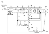
- an inverter for an electric vehicle including: a speed instruction generating unit configured to output a speed instruction for changing the rotational frequency of an electric motor based on the on/off of a signal outputted from the accelerator pedal; a frequency voltage converting unit configured to output a voltage instruction based on the frequency of the speed instruction; an integrator configured to output a rotational angle by performing integration on the frequency of the speed instruction; and a 2-to-3 phase converter configured to receive the voltage instruction and the rotational angle and convert the received voltage instruction and rotational angle into three-phase voltage instructions.
- the speed instruction generating unit may include a storage in which a maximum frequency at which the electric motor is rotated, a frequency increment and a frequency decrement are stored; and a control unit configured to increase the frequency of the speed instruction by the frequency increment when the accelerator pedal is on, and decrease the frequency of the speed instruction by the frequency decrement when the accelerator pedal is off.
- the frequency voltage converting unit outputs a voltage instruction of the electric motor, obtained by multiplying the frequency of the speed instruction by a ratio of rated voltage/rated frequency.
- FIG. 1 is a block configuration view of an inverter for an electric vehicle, implemented by a vector control method using an output value of a position sensor;
- FIG. 2 is a graph showing torque of an induction motor, generated according to the degree of pushing of an accelerator pedal, by the vector control method
- FIG. 3 is a block configuration view of an inverter for an electric vehicle, implemented by a voltage/frequency control method according to an embodiment of the present invention
- FIG. 4 is a flowchart illustrating a voltage/frequency control method of a speed instruction generating unit according to the embodiment of the present invention.
- FIG. 5 is a graph showing a frequency instruction of the speed instruction generating unit according to the degree of pushing of an accelerator pedal, generated by the voltage/frequency control method according to the embodiment of the present invention.
- FIG. 1 is a block configuration view of an inverter for an electric vehicle, implemented by a vector control method using an output value of a position sensor.
- the inverter for the electric vehicle will be described, which is implemented by the vector control method of independently controlling the flux current and torque current of an electric motor having a speed sensor attached thereto.
- the inverter 100 for the electric vehicle implemented by the vector control method, outputs a voltage capable of rotating an electric motor 101 so as to drive the electric vehicle at a speed desired by a driver through the driver's operation of an accelerator pedal of the electric vehicle.
- An integrator 116 calculates a slip angle ⁇ sl by performing integration on the slip frequency W sl .
- the method of independently controlling the magnetic flux current and the torque current using the control method of the magnetic angle ⁇ e of the rotor is referred to as an indirect vector control method.
- FIG. 2 is a graph showing torque of an induction motor, generated according to the degree of pushing of an accelerator pedal, by the vector control method.
- the driver operates a state 503 of the accelerator pedal so that a speed 502 of the electric vehicle approaches a speed 501 of the electric vehicle, at which the driver intends to drive.
- the speed instruction generating unit increases or decreases a frequency instruction 504 at a predetermined rate, corresponding to the on- or off-state of the accelerator pedal.
Landscapes
- Engineering & Computer Science (AREA)
- Power Engineering (AREA)
- Transportation (AREA)
- Mechanical Engineering (AREA)
- Life Sciences & Earth Sciences (AREA)
- Sustainable Development (AREA)
- Sustainable Energy (AREA)
- Control Of Ac Motors In General (AREA)
- Electric Propulsion And Braking For Vehicles (AREA)
Applications Claiming Priority (1)
| Application Number | Priority Date | Filing Date | Title |
|---|---|---|---|
| KR20100064117A KR101494030B1 (ko) | 2010-07-02 | 2010-07-02 | 전기자동차용 인버터 |
Publications (2)
| Publication Number | Publication Date |
|---|---|
| EP2402207A2 true EP2402207A2 (de) | 2012-01-04 |
| EP2402207A3 EP2402207A3 (de) | 2016-12-07 |
Family
ID=44863368
Family Applications (1)
| Application Number | Title | Priority Date | Filing Date |
|---|---|---|---|
| EP11169250.5A Withdrawn EP2402207A3 (de) | 2010-07-02 | 2011-06-09 | Umrichter für elektrische Fahrzeuge |
Country Status (4)
| Country | Link |
|---|---|
| US (1) | US8461791B2 (de) |
| EP (1) | EP2402207A3 (de) |
| KR (1) | KR101494030B1 (de) |
| CN (1) | CN102315818B (de) |
Family Cites Families (39)
| Publication number | Priority date | Publication date | Assignee | Title |
|---|---|---|---|---|
| DE2701567C2 (de) * | 1977-01-15 | 1987-03-26 | Robert Bosch Gmbh, 7000 Stuttgart | Geschwindigkeitssteuereinrichtung für Fahrzeuge |
| EP0016548B1 (de) * | 1979-03-14 | 1984-12-27 | LUCAS INDUSTRIES public limited company | Brennstoffsteuersystem für eine Brennkraftmaschine |
| DE3069850D1 (en) * | 1979-03-14 | 1985-02-07 | Lucas Ind Plc | Fuel control system for an internal combustion engine |
| DE3033541A1 (de) * | 1980-09-05 | 1982-04-22 | Still Gmbh, 2000 Hamburg | Antriebsaggregat fuer ein kraftfahrzeug, schaltung fuer ein solches und verfahren zum betreiben eines solchen |
| JPS5951150A (ja) * | 1982-09-16 | 1984-03-24 | Nissan Motor Co Ltd | 内燃機関のアイドル回転速度制御方法 |
| US4727490A (en) * | 1984-03-07 | 1988-02-23 | Kabushiki Kaisha Toyoda Jidoshokki Seisakusho | Running control device on cargo handling vehicles |
| DE3417089A1 (de) * | 1984-05-09 | 1985-11-14 | Robert Bosch Gmbh, 7000 Stuttgart | Vortriebsregeleinrichtung |
| US4766967A (en) * | 1985-12-27 | 1988-08-30 | Eaton Corporation | Oscillation control system for electric motor drive |
| JPS6311451A (ja) * | 1986-07-01 | 1988-01-18 | Nissan Motor Co Ltd | 無段変速機の制御装置 |
| DE3704316A1 (de) * | 1987-02-12 | 1988-08-25 | Vdo Schindling | Verfahren und schaltungsanordnung zum verhindern von schwingungen eines kraftfahrzeugs |
| US4915075A (en) * | 1989-03-20 | 1990-04-10 | Caterpillar Inc. | Accelerator pedal position sensor |
| GB8908661D0 (en) * | 1989-04-17 | 1989-06-01 | Lucas Ind Plc | Engine throttle control system |
| US5193506A (en) * | 1989-04-17 | 1993-03-16 | Lucas Industries Public Limited Company | Engine throttle control system |
| US5255653A (en) * | 1989-04-17 | 1993-10-26 | Lucas Industries Public Limited Company | Engine throttle control system |
| JPH04176736A (ja) * | 1990-11-09 | 1992-06-24 | Mitsubishi Electric Corp | 車両用定速走行制御装置 |
| DE69321382T2 (de) * | 1992-02-17 | 1999-06-02 | Hitachi, Ltd., Tokio/Tokyo | Ein Sensor zur Erfassung von Differenzbeschleunigung. |
| JP3232823B2 (ja) * | 1993-11-16 | 2001-11-26 | 株式会社日立製作所 | 電気自動車の回生制動制御方法 |
| JPH08140202A (ja) * | 1994-11-07 | 1996-05-31 | Hitachi Ltd | 電気車用保護装置及び保護方法 |
| KR100258308B1 (ko) * | 1997-11-26 | 2000-06-01 | 정명식 | 유도 모터 제어 방법 및 제어용 인버터 |
| KR100459470B1 (ko) * | 1998-02-14 | 2005-05-03 | 엘지산전 주식회사 | 유도전동기에서 고주파 주입을이용한 속도 센서리스 벡터 제어기 |
| KR100289496B1 (ko) * | 1999-01-15 | 2001-05-02 | 윤종용 | 고속모터의 센서리스 속도제어방법 |
| JP3538057B2 (ja) | 1999-02-25 | 2004-06-14 | 財団法人鉄道総合技術研究所 | 速度センサレス制御を用いた電気車制御装置 |
| US8135531B2 (en) * | 2002-06-12 | 2012-03-13 | Nmhg Oregon, Llc | Predictive vehicle controller |
| JP3926703B2 (ja) * | 2002-08-08 | 2007-06-06 | 本田技研工業株式会社 | 制御装置 |
| JP3979289B2 (ja) * | 2002-12-26 | 2007-09-19 | アイシン・エィ・ダブリュ株式会社 | 電動駆動制御装置、電動駆動制御方法及びそのプログラム |
| JP2005027410A (ja) * | 2003-07-01 | 2005-01-27 | Tsudakoma Corp | 誘導電動機の駆動方法および駆動装置 |
| US7222011B2 (en) * | 2004-07-23 | 2007-05-22 | General Motors Corporation | Engine and driveline torque transfer device control |
| FR2881296B1 (fr) * | 2005-01-27 | 2007-03-09 | Schneider Toshiba Inverter | Procede et systeme de limitation du courant en sortie d'un variateur de vitesse fonctionnant selon une loi de commande u/f |
| US7938494B2 (en) * | 2006-03-08 | 2011-05-10 | Ribbens William B | Antilock braking systems and methods |
| WO2008092274A1 (en) * | 2007-01-30 | 2008-08-07 | Gordon Ewbank Dower | Vehicle power and speed control systems |
| KR100798342B1 (ko) * | 2007-01-31 | 2008-01-28 | 엘에스산전 주식회사 | 인버터의 가 감속 시간과 관성에 따른 제어장치 및 그 방법 |
| US7549407B2 (en) * | 2007-03-28 | 2009-06-23 | Gm Global Technology Operations, Inc. | Method and system for controlling a valve device |
| KR100976309B1 (ko) * | 2007-12-28 | 2010-08-16 | 엘에스산전 주식회사 | 인버터의 제어장치 |
| US7932691B2 (en) * | 2008-04-22 | 2011-04-26 | GM Global Technology Operations LLC | Permanent magnet motor start-up |
| JP2009291019A (ja) | 2008-05-30 | 2009-12-10 | Toyota Motor Corp | 交流モータ用インバータの制御装置 |
| US8616181B2 (en) * | 2008-07-11 | 2013-12-31 | Tula Technology, Inc. | Internal combustion engine control for improved fuel efficiency |
| US7577511B1 (en) * | 2008-07-11 | 2009-08-18 | Tula Technology, Inc. | Internal combustion engine control for improved fuel efficiency |
| US8336521B2 (en) * | 2008-07-11 | 2012-12-25 | Tula Technology, Inc. | Internal combustion engine control for improved fuel efficiency |
| US8131447B2 (en) * | 2008-07-11 | 2012-03-06 | Tula Technology, Inc. | Internal combustion engine control for improved fuel efficiency |
-
2010
- 2010-07-02 KR KR20100064117A patent/KR101494030B1/ko not_active Expired - Fee Related
-
2011
- 2011-06-09 EP EP11169250.5A patent/EP2402207A3/de not_active Withdrawn
- 2011-06-15 US US13/161,398 patent/US8461791B2/en not_active Expired - Fee Related
- 2011-07-01 CN CN201110189374.9A patent/CN102315818B/zh not_active Expired - Fee Related
Non-Patent Citations (1)
| Title |
|---|
| None |
Also Published As
| Publication number | Publication date |
|---|---|
| US8461791B2 (en) | 2013-06-11 |
| CN102315818A (zh) | 2012-01-11 |
| KR101494030B1 (ko) | 2015-02-16 |
| EP2402207A3 (de) | 2016-12-07 |
| CN102315818B (zh) | 2014-03-19 |
| US20120001578A1 (en) | 2012-01-05 |
| KR20120003331A (ko) | 2012-01-10 |
Similar Documents
| Publication | Publication Date | Title |
|---|---|---|
| US6984957B2 (en) | Apparatus for controlling permanent-magnet rotary machine | |
| CN105128696B (zh) | 直流总线电压控制 | |
| EP1193854B1 (de) | Motorregelvorrichtung und regelverfahren | |
| US7847501B2 (en) | Varying flux versus torque for maximum efficiency | |
| US20070182350A1 (en) | Method and apparatus for controlling an electric motor | |
| US20110241583A1 (en) | Control device of motor driving apparatus | |
| US20110241584A1 (en) | Control device of motor driving apparatus | |
| US9120388B2 (en) | Rotating electrical machine drive system | |
| US9837888B2 (en) | Boost control apparatus based on output current change amount | |
| EP2681839A1 (de) | Verfahren zur steuerung eines motors | |
| US20060273747A1 (en) | Controlling for motor driving vehicle | |
| US10164551B2 (en) | Boost control apparatus based on output current change rate | |
| US20180337623A1 (en) | Drive device and control method for drive device | |
| US7443127B2 (en) | Apparatus and method for motor control using table | |
| US20140225542A1 (en) | Control device of ac motor | |
| US10396698B2 (en) | Drive device and drive system | |
| US10348188B2 (en) | Vehicle and control method therefor | |
| JPH08275599A (ja) | 永久磁石同期電動機の制御方法 | |
| JP2002084780A (ja) | モータ制御装置 | |
| JP5760831B2 (ja) | モータ制御装置 | |
| JP5055836B2 (ja) | 同期モーター用磁極位置センサーの位相ズレ検出装置および検出方法 | |
| EP2402207A2 (de) | Umrichter für elektrische Fahrzeuge | |
| US20160352274A1 (en) | System of controlling induction electric motor | |
| JP3489259B2 (ja) | 永久磁石形電動機制御方法及び制御装置 | |
| JP5023718B2 (ja) | 車両用駆動制御装置及び車両用駆動制御方法 |
Legal Events
| Date | Code | Title | Description |
|---|---|---|---|
| AK | Designated contracting states |
Kind code of ref document: A2 Designated state(s): AL AT BE BG CH CY CZ DE DK EE ES FI FR GB GR HR HU IE IS IT LI LT LU LV MC MK MT NL NO PL PT RO RS SE SI SK SM TR |
|
| AX | Request for extension of the european patent |
Extension state: BA ME |
|
| PUAI | Public reference made under article 153(3) epc to a published international application that has entered the european phase |
Free format text: ORIGINAL CODE: 0009012 |
|
| PUAL | Search report despatched |
Free format text: ORIGINAL CODE: 0009013 |
|
| AK | Designated contracting states |
Kind code of ref document: A3 Designated state(s): AL AT BE BG CH CY CZ DE DK EE ES FI FR GB GR HR HU IE IS IT LI LT LU LV MC MK MT NL NO PL PT RO RS SE SI SK SM TR |
|
| AX | Request for extension of the european patent |
Extension state: BA ME |
|
| RIC1 | Information provided on ipc code assigned before grant |
Ipc: H02P 27/04 20060101ALI20161103BHEP Ipc: B60L 15/20 20060101AFI20161103BHEP Ipc: H02P 21/08 20160101ALI20161103BHEP |
|
| STAA | Information on the status of an ep patent application or granted ep patent |
Free format text: STATUS: THE APPLICATION IS DEEMED TO BE WITHDRAWN |
|
| 18D | Application deemed to be withdrawn |
Effective date: 20170608 |