EP2402206A2 - SOC-korriegierbare Stromversorgungsvorrichtung für Hybridfahrzeug - Google Patents
SOC-korriegierbare Stromversorgungsvorrichtung für Hybridfahrzeug Download PDFInfo
- Publication number
- EP2402206A2 EP2402206A2 EP11005197A EP11005197A EP2402206A2 EP 2402206 A2 EP2402206 A2 EP 2402206A2 EP 11005197 A EP11005197 A EP 11005197A EP 11005197 A EP11005197 A EP 11005197A EP 2402206 A2 EP2402206 A2 EP 2402206A2
- Authority
- EP
- European Patent Office
- Prior art keywords
- soc
- battery
- power supply
- supply device
- car
- Prior art date
- Legal status (The legal status is an assumption and is not a legal conclusion. Google has not performed a legal analysis and makes no representation as to the accuracy of the status listed.)
- Withdrawn
Links
Images


Classifications
-
- B—PERFORMING OPERATIONS; TRANSPORTING
- B60—VEHICLES IN GENERAL
- B60L—PROPULSION OF ELECTRICALLY-PROPELLED VEHICLES; SUPPLYING ELECTRIC POWER FOR AUXILIARY EQUIPMENT OF ELECTRICALLY-PROPELLED VEHICLES; ELECTRODYNAMIC BRAKE SYSTEMS FOR VEHICLES IN GENERAL; MAGNETIC SUSPENSION OR LEVITATION FOR VEHICLES; MONITORING OPERATING VARIABLES OF ELECTRICALLY-PROPELLED VEHICLES; ELECTRIC SAFETY DEVICES FOR ELECTRICALLY-PROPELLED VEHICLES
- B60L58/00—Methods or circuit arrangements for monitoring or controlling batteries or fuel cells, specially adapted for electric vehicles
- B60L58/10—Methods or circuit arrangements for monitoring or controlling batteries or fuel cells, specially adapted for electric vehicles for monitoring or controlling batteries
- B60L58/12—Methods or circuit arrangements for monitoring or controlling batteries or fuel cells, specially adapted for electric vehicles for monitoring or controlling batteries responding to state of charge [SoC]
- B60L58/15—Preventing overcharging
-
- B—PERFORMING OPERATIONS; TRANSPORTING
- B60—VEHICLES IN GENERAL
- B60L—PROPULSION OF ELECTRICALLY-PROPELLED VEHICLES; SUPPLYING ELECTRIC POWER FOR AUXILIARY EQUIPMENT OF ELECTRICALLY-PROPELLED VEHICLES; ELECTRODYNAMIC BRAKE SYSTEMS FOR VEHICLES IN GENERAL; MAGNETIC SUSPENSION OR LEVITATION FOR VEHICLES; MONITORING OPERATING VARIABLES OF ELECTRICALLY-PROPELLED VEHICLES; ELECTRIC SAFETY DEVICES FOR ELECTRICALLY-PROPELLED VEHICLES
- B60L58/00—Methods or circuit arrangements for monitoring or controlling batteries or fuel cells, specially adapted for electric vehicles
- B60L58/10—Methods or circuit arrangements for monitoring or controlling batteries or fuel cells, specially adapted for electric vehicles for monitoring or controlling batteries
- B60L58/12—Methods or circuit arrangements for monitoring or controlling batteries or fuel cells, specially adapted for electric vehicles for monitoring or controlling batteries responding to state of charge [SoC]
-
- B—PERFORMING OPERATIONS; TRANSPORTING
- B60—VEHICLES IN GENERAL
- B60W—CONJOINT CONTROL OF VEHICLE SUB-UNITS OF DIFFERENT TYPE OR DIFFERENT FUNCTION; CONTROL SYSTEMS SPECIALLY ADAPTED FOR HYBRID VEHICLES; ROAD VEHICLE DRIVE CONTROL SYSTEMS FOR PURPOSES NOT RELATED TO THE CONTROL OF A PARTICULAR SUB-UNIT
- B60W10/00—Conjoint control of vehicle sub-units of different type or different function
- B60W10/24—Conjoint control of vehicle sub-units of different type or different function including control of energy storage means
-
- B—PERFORMING OPERATIONS; TRANSPORTING
- B60—VEHICLES IN GENERAL
- B60L—PROPULSION OF ELECTRICALLY-PROPELLED VEHICLES; SUPPLYING ELECTRIC POWER FOR AUXILIARY EQUIPMENT OF ELECTRICALLY-PROPELLED VEHICLES; ELECTRODYNAMIC BRAKE SYSTEMS FOR VEHICLES IN GENERAL; MAGNETIC SUSPENSION OR LEVITATION FOR VEHICLES; MONITORING OPERATING VARIABLES OF ELECTRICALLY-PROPELLED VEHICLES; ELECTRIC SAFETY DEVICES FOR ELECTRICALLY-PROPELLED VEHICLES
- B60L50/00—Electric propulsion with power supplied within the vehicle
- B60L50/50—Electric propulsion with power supplied within the vehicle using propulsion power supplied by batteries or fuel cells
-
- H—ELECTRICITY
- H01—ELECTRIC ELEMENTS
- H01M—PROCESSES OR MEANS, e.g. BATTERIES, FOR THE DIRECT CONVERSION OF CHEMICAL ENERGY INTO ELECTRICAL ENERGY
- H01M10/00—Secondary cells; Manufacture thereof
- H01M10/42—Methods or arrangements for servicing or maintenance of secondary cells or secondary half-cells
- H01M10/44—Methods for charging or discharging
-
- H—ELECTRICITY
- H02—GENERATION; CONVERSION OR DISTRIBUTION OF ELECTRIC POWER
- H02J—CIRCUIT ARRANGEMENTS OR SYSTEMS FOR SUPPLYING OR DISTRIBUTING ELECTRIC POWER; SYSTEMS FOR STORING ELECTRIC ENERGY
- H02J7/00—Circuit arrangements for charging or depolarising batteries or for supplying loads from batteries
-
- Y—GENERAL TAGGING OF NEW TECHNOLOGICAL DEVELOPMENTS; GENERAL TAGGING OF CROSS-SECTIONAL TECHNOLOGIES SPANNING OVER SEVERAL SECTIONS OF THE IPC; TECHNICAL SUBJECTS COVERED BY FORMER USPC CROSS-REFERENCE ART COLLECTIONS [XRACs] AND DIGESTS
- Y02—TECHNOLOGIES OR APPLICATIONS FOR MITIGATION OR ADAPTATION AGAINST CLIMATE CHANGE
- Y02E—REDUCTION OF GREENHOUSE GAS [GHG] EMISSIONS, RELATED TO ENERGY GENERATION, TRANSMISSION OR DISTRIBUTION
- Y02E60/00—Enabling technologies; Technologies with a potential or indirect contribution to GHG emissions mitigation
- Y02E60/10—Energy storage using batteries
-
- Y—GENERAL TAGGING OF NEW TECHNOLOGICAL DEVELOPMENTS; GENERAL TAGGING OF CROSS-SECTIONAL TECHNOLOGIES SPANNING OVER SEVERAL SECTIONS OF THE IPC; TECHNICAL SUBJECTS COVERED BY FORMER USPC CROSS-REFERENCE ART COLLECTIONS [XRACs] AND DIGESTS
- Y02—TECHNOLOGIES OR APPLICATIONS FOR MITIGATION OR ADAPTATION AGAINST CLIMATE CHANGE
- Y02T—CLIMATE CHANGE MITIGATION TECHNOLOGIES RELATED TO TRANSPORTATION
- Y02T10/00—Road transport of goods or passengers
- Y02T10/60—Other road transportation technologies with climate change mitigation effect
- Y02T10/70—Energy storage systems for electromobility, e.g. batteries
-
- Y—GENERAL TAGGING OF NEW TECHNOLOGICAL DEVELOPMENTS; GENERAL TAGGING OF CROSS-SECTIONAL TECHNOLOGIES SPANNING OVER SEVERAL SECTIONS OF THE IPC; TECHNICAL SUBJECTS COVERED BY FORMER USPC CROSS-REFERENCE ART COLLECTIONS [XRACs] AND DIGESTS
- Y02—TECHNOLOGIES OR APPLICATIONS FOR MITIGATION OR ADAPTATION AGAINST CLIMATE CHANGE
- Y02T—CLIMATE CHANGE MITIGATION TECHNOLOGIES RELATED TO TRANSPORTATION
- Y02T10/00—Road transport of goods or passengers
- Y02T10/60—Other road transportation technologies with climate change mitigation effect
- Y02T10/72—Electric energy management in electromobility
Definitions
- the present invention relates to a power supply device that is installed on a hybrid car and supplies electric power to an electric motor of the hybrid car, and in particular to a power supply device that is installed on a hybrid car and transmits SOC of a battery to the car.
- a power supply device installed on a hybrid car detects SOC of battery, and transmits the detected SOC to the car.
- SOC of a battery refers to a rate of a capacity that can be discharged from the battery relative to the fully-charged capacity. In the case where a battery has a fully-charged capacity of 6 Ah, when a capacity of the battery is 3 Ah that can be discharged from the battery until the battery is completely discharged, the battery has SOC of 50%. SOC of the battery is 100% when the battery is fully charged. SOC of the battery is 0% when the battery is completely discharged.
- the car controls the charging/discharging operation of the battery based on SOC transmitted from the power supply device (See Laid-Open Patent Publication No. JP 2003-47108 A ).
- the power supply device of a hybrid car disclosed in this Publication controls the charging/discharging operation of the battery so that SOC of the battery falls within a predetermined range. If SOC of the battery becomes large, discharging operation is allowed while charging operation is limited so that SOC can be reduced. On the other hand, if SOC of the battery becomes small, discharging operation is limited while charging operation is allowed so that SOC can be increased.
- the hybrid car controls electric devices such as air-conditioner installed on the car based on SOC of the driving battery. For example, if SOC of the battery becomes small, the air-conditioner is stopped. On the other hand, if SOC of the battery becomes large, the air-conditioner is allowed to operate. The reason is to prevent that the battery is over-discharged due to air-conditioner operation. In the case where the hybrid car is brought in a stop, its engine is stopped. However, even in this case, the power supply device is controlled so that, if SOC of the battery becomes small, the engine is started to charge the battery. Also, if SOC of the battery is increased to a predetermined value, the engine is stopped.
- the power supply device detects SOC based on the accumulated values of current in charging/discharging operation of the battery, and the voltage of the battery.
- SOC is calculated by adding accumulated values of charging current to the previous SOC and by subtracting accumulated values of discharging current from the previous SOC.
- the detected SOC will have an error, which increases with time. Accordingly, SOC is detected in consideration of the voltage of the battery in addition to the accumulated values of current.
- the voltage of the battery increases as SOC increases, and decreases as SOC decreases.
- the voltage of the battery is not specified only by SOC.
- the voltage of the battery varies depending on other various parameters including whether the battery is charged or discharged, and temperature. For this reason, SOC cannot be accurately detected only based on voltage.
- the power supply device of the hybrid car detects SOC based on both the accumulated value of current, and voltage.
- SOC can be more accurately detected as SOC of the battery gets closer to 100% when the battery is charged, and as SOC of the battery gets closer to 0% when the battery is discharged. Accordingly, in the case where the weight of voltage is increased in SOC detection as SOC of the battery gets closer to 100%, or as SOC of the battery gets closer to 0%, SOC can be accurately detected.
- SOC of the battery is accurately detected based on voltage in the ranges where SOC is closer to 100% or 0%, there is time difference between the voltage increase and SOC increase of the battery. As discussed above, SOC of the battery detected by the power supply device includes an error caused by various reasons.
- the present invention has been developed for solving the aforementioned problem. It is an important object of the present invention to provide a power supply device for a hybrid car that can suppress that correction of SOC transmitted to the car causes ON/OFF switching repetition of electric devices such as air-conditioner installed on the car and start/stop repetition of an engine of the car whereby providing a comfortable driver environment.
- a power supply device of a hybrid car includes a driving battery 1 and a battery management system 2.
- the driving battery 1 can supply electric power to an electric motor 13 for driving the car.
- the battery management system 2 detects SOC of the driving battery 1, and transmits the detected SOC to the car.
- the battery management system 2 stores maximum SOC and minimum SOC relating to transmission of SOC of the battery to the car.
- the detected SOC of the battery falls within a range between the maximum SOC and the minimum SOC
- the detected SOC of the battery is transmitted to the car.
- the maximum SOC is transmitted to the car.
- the minimum SOC is transmitted to the car.
- the thus-constructed power supply device of a hybrid car has a feature that it is possible to suppress that correction of SOC transmitted to the car causes ON/OFF switching repetition of electric devices such as air-conditioner installed on the car and start/stop repetition of an engine of the car whereby providing a comfortable driver environment.
- the maximum SOC stored by the battery management system 2 can be set at a value falling within a range of 65% to 75%, and the minimum SOC stored by the battery management system 2 can be set at a value falling within a range of 25% to 35%. According to the thus-constructed power supply device, it is possible to prevent that the battery is over-charged/over-discharged, and additionally to suppress ON/OFF switching repetition of electric devices such as air-conditioner installed on the car and start/stop repetition of an engine of the car whereby providing a comfortable driver environment.
- the battery management system 2 can store a maximum variation rate of SOC relating to transmission of variation rate of SOC of the battery to the car.
- the variation rate of the detected SOC of the battery is higher than the maximum variation rate
- the variation rate of SOC to be transmitted to the car can be limited to the maximum variation rate so that the maximum variation rate is transmitted to the car in transmission of variation rate of SOC. According to the thus-constructed power supply device, it is possible to correcting the error of calculated SOC, and additionally prevent ON/OFF repetition of electric devices and an engine of the car.
- the maximum variation rate in SOC decrease stored by the battery management system 2 can be set at a value smaller than the SOC decrease rate where the driving battery 1 is discharged at a predetermined maximum current.
- the thus-constructed power supply device has a feature that, even if a detection error occurs so that the detected SOC too much sharply varies, a stable SOC value can be transmitted to the car.
- the maximum variation rate in SOC increase stored by the battery management system 2 can be set at a value smaller than the SOC increase rate where the driving battery 1 is charged at a predetermined maximum current.
- the thus-constructed power supply device has a feature that, even if a detection error occurs so that the detected SOC too much sharply varies, a stable SOC value can be transmitted to the car.
- the battery management system 2 can store different maximum variation rate values corresponding to SOC decrease and SOC increase. According to the thus-constructed power supply device, if the detected SOC too much sharply increases and decreases, it is possible to correct the detected SOC so that a stable SOC value can be transmitted to the car both in the SOC increase and decrease cases.
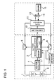
- Fig. 1 is a block diagram of a power supply device of a hybrid car according to an embodiment of the present invention
- a power supply device of a hybrid car shown in Fig. 1 includes a driving battery 1 and a battery management system 2.
- the driving battery 1 can supply electric power to an electric motor 13 for driving the car.
- the battery management system 2 detects SOC of the driving battery 1, and transmits the detected SOC to the car.
- the car includes a control circuit 12 that controls a DC/AC inverter 11 based on signals transmitted from the battery management system 2.
- the DC/AC inverter 11 is connected to the electric motor 13 for driving the car, and an electric generator 14 for charging the driving battery 1.
- the electric generator 14 can charge the driving battery 1 when driven by an engine 15, and can charge the driving battery 1 when rotated by regenerative braking in car braking.
- the control circuit 12 controls the DC/AC inverter 11.
- the electric motor 13 and the electric generator 14 are controlled so that SOC of the driving battery 1 is held in a predetermined range, for example, SOC is held in a range of 50% ⁇ 20%.
- the control circuit 12 controls the electric motor 13 and the electric generator 14 through the DC/AC inverter 11 so that SOC of the driving battery 1 is held in the range of 50% ⁇ 20%.
- the control circuit 12 controls the electric motor 13 and the electric generator 14 based on signals provided from an accelerator pedal and a brake pedal while holding SOC in the predetermine range. For example, when the accelerator pedal is pressed down to accelerate the car, the electric motor 13 is supplied with electric power so that the car is accelerated by the power outputs of both the electric motor 13 and the engine 15. Also, in the case where the car travels at a low speed, the car can be driven only by the electric motor 13 with the engine 15 being stopped. In this case, if SOC of the driving battery 1 decreases, the engine 15 is started so that the car will be driven by both the engine 15 and the electric motor 13 with the driving battery 1 being charged.
- the electric generator 14 is rotated by wheels so that the driving battery 1 is charged. That is, the driving battery 1 can be charged by regenerative braking.
- SOC of the driving battery 1 increases to 70%, the engine 15 is stopped, which in turn stops charging operation of the driving battery 1.
- the battery management system 2 detects SOC of the driving battery 1 to be charged/discharged, in order to charge/discharge the driving battery 1 with SOC being held in the predetermined range. SOC is detected based on the accumulated value of charging/discharging current, and voltage.
- the power supply device detects SOC based on signals from a current detecting circuit 3, a voltage detecting circuit 4 and a temperature detecting circuit 5.
- the current detecting circuit 3 detects current flowing the driving battery 1.
- the voltage detecting circuit 4 detects the voltage of the driving battery 1.
- the temperature detecting circuit 5 detects the temperature of the driving battery 1.
- the battery management system 2 calculates SOC by adding accumulated values of charging current of the driving battery 1 to the previous SOC and by subtracting accumulated values of discharging current of the driving battery 1 from the previous SOC. In addition, SOC is calculated based on the voltage of the driving battery 1.
- the battery management system 2 calculates SOC according to the following formula based on the accumulation-based SOC calculated based on the accumulated values, and the voltage-based SOC detected based on the voltage.
- the weight 1 and the weight 2 are changed in accordance with the voltage of the battery.
- Fig. 2 shows the change in the ratio between weight 1 and weight 2 in accordance with the voltage of the battery.
- a memory 7 of the battery management system 2 stores the change in the ratio between weight 1 and weight 2 in accordance with the voltage.
- the battery management system 2 corrects SOC based on the temperature of the battery to more accurately detect SOC.
- SOC of the driving battery 1 can be more accurately detected by correcting the charging efficiency and discharging efficiency, or the voltage of the battery based on the temperature of the battery.
- the driving battery 1 In car traveling, the driving battery 1 is charged/discharged so that SOC varies.
- the battery management system 2 detects SOC of the driving battery 1, which varies, and transmits the detected SOC to the control circuit of the car.
- the battery management system 2 does not transmit the detected SOC of the driving battery 1 as it is to the control circuit of the car.
- the battery management system 2 stores maximum SOC and minimum SOC in transmission of SOC of the battery to the car.
- the battery management system 2 transmits the detected SOC of the battery to the control circuit of the car.
- the battery management system 2 When the detected SOC of the battery is not lower than the maximum SOC, the battery management system 2 transmits the maximum SOC to the control circuit of the car.
- the battery management system 2 transmits the minimum SOC is transmitted to the control circuit of the car.
- the battery management system 2 stores a maximum variation rate relating to transmission of variation rate of SOC of the battery to the car.
- the variation rate of the detected SOC of the battery is higher than the maximum variation rate
- the variation rate of SOC to be transmitted to the control circuit of the car is corrected and limited to the maximum variation rate so that the maximum variation rate is transmitted to the control circuit of the car in transmission of variation rate of SOC.
- a SOC variation rate per second has a maximum limitation up to this maximum variation rate, which is set at a value smaller than the SOC decrease rate where the driving battery 1 is discharged at a predetermined maximum current.
- the maximum available current flowing through the driving battery 1 is previously determined.
- the driving battery 1 is not discharged at a current higher than the maximum current in any conditions. For example, if the driving battery 1 has a rated capacity of 6 Ah, when the driving battery 1 is discharged at 200 A for 1 second, the SOC decrease is calculated at 0.926%. In the case the maximum available current flowing through the driving battery 1 is 200 A, the driving battery 1 is discharged at a current not larger than 200 A. For this reason, the variation rate of SOC does not exceed 0.926% unless SOC is corrected. In the case where the maximum variation rate of SOC is set at a value not larger than 0.926%, a stable SOC variation rates can be transmitted to the control circuit of the car.
- the stored maximum variation rate is set at a value not less than 70%, preferably not less than 80%, and more preferably not less than 90% of the SOC decrease where the driving battery is discharged at the maximum available current.
- the maximum variation rate is switched between the SOC decrease case where the driving battery 1 is discharged and the SOC increase where the driving battery 1 is charged.
- the maximum available charging and discharging current values of the driving battery 1 are 50 A and 200 A, respectively.
- the maximum SOC increase rate in charging operation is 0.23%.
- the maximum variation rate of SOC when SOC increases is set at a value not larger than 0.23%, a stable SOC variation rates can be transmitted to the control circuit of the car.
- the maximum variation rate is set at a too small value, accurate SOC cannot be transmitted to the control circuit of the car.
- the stored maximum variation rate is set at a value not less than 70%, preferably not less than 80%, and more preferably not less than 90% of the SOC increase where the driving battery is charged at the maximum available current.
- Figs. 3 and 4 the dashed lines indicate SOC of the driving battery 1 detected by the battery management system 2, and the thick lines indicate SOC to be transmitted to the control circuit of the car.
- Fig. 3 is a graph showing variation where SOC of the driving battery 1 detected by the battery management system 2 varies into a range exceeding the maximum SOC, and the detected SOC varies too much sharply.
- the control circuit of the car is provided with to-be-transmitted SOC shown by the thick line in Fig. 3 . That is, when the detected SOC exceeds the maximum SOC, the maximum SOC is transmitted to the control circuit of the car.
- the variation rate of the detected SOC exceeds the maximum variation rate, to-be-transmitted SOC is changed from the detected SOC correspondingly to the maximum variation rate.
- Fig. 4 is a graph showing variation where SOC of the driving battery 1 detected by the battery management system 2 varies into a range lower than the minimum SOC, and the detected SOC varies too much sharply.
- the control circuit of the car is provided with to-be-transmitted SOC shown by the thick line in Fig. 4 . That is, when the detected SOC is lower than the minimum SOC, the minimum SOC is transmitted to the control circuit of the car.
- the variation rate of the detected SOC exceeds the maximum variation rate, to-be-transmitted SOC is changed from the detected SOC correspondingly to the maximum variation rate.
- the control circuit of the car cannot determine whether the driving battery 1 is charged/discharged to abnormal states.
- contactors 6 are connected to the positive and negative output sides of the driving battery 1 of the power supply device.
- the contactors 6 are controlled by a protection circuit 8 of the battery management system 2. If the driving battery 1 is brought into an over-charged state, the protection circuit 8 of the battery management system 2 opens the contactors 6 and prevents that the driving battery 1 is over-charged.
- the protection circuit 8 of the battery management system 2 also opens the contactors 6 and forcedly stops discharging operation of the driving battery 1.
- Fig. 5 shows a power supply device which can be used not only as power supply of mobile unit such as vehicle but also as stationary power storage.
- This power supply device can be used as, for example, examples of stationary power storage devices can be provided by an electric power system for home use or plant use that is charged with solar electric power or with midnight electric power and is discharged when necessary, a power supply for street lights that is charged with solar electric power during the daytime and is discharged during the nighttime, or a backup power supply for signal lights that drives signal lights in the event of a power failure.
- Fig. 5 shows a circuit diagram according to this embodiment.
- This illustrated power supply device 100 includes battery units 82 each of which includes a plurality of battery packs 81 that are connected to each other.
- each of battery packs 81 a plurality of battery cells are connected to each other in serial and/or in parallel.
- the battery packs 81 are controlled by a power supply controller 84.
- the power supply device 100 After the battery units 82 are charged by a charging power supply CP, the power supply device 100 drives a load LD.
- the power supply device 100 has a charging mode and a discharging mode.
- the Load LD and the charging power supply CP are connected to the power supply device 100 through a discharging switch DS and a charging switch CS, respectively.
- the discharging switch DS and the charging operation switch CS are turned ON/OFF by the power supply controller 84 of the power supply device 100.
- the power supply controller 84 turns charging operation switch CS ON, and turns the discharging switch DS OFF so that the power supply device 100 can be charged by the charging power supply CP.
- the power supply controller 84 turns the charging operation switch CS OFF, and turns the discharging switch DS ON.
- the charging operation switch CS may be turned ON, while the discharging switch DS may be turned ON so that the load LD can be supplied with electric power while the power supply device 100 can be charged.
- the load LD driven by the power supply device 100 is connected to the power supply device 100 through the discharging switch DS.
- the power supply controller 84 turns the discharging switch DS ON so that the power supply device 100 is connected to the load LD.
- the load LD is driven with electric power from the power supply device 100.
- Switching elements such as FET can be used as the discharging switch DS.
- the discharging switch DS is turned ON/OFF by the power supply controller 84 of the power supply device 100.
- the power supply controller 84 includes a communication interface for communicating with an external device. In the power supply device according to the embodiment shown in Fig.
- the power supply controller is connected to a host device HT based on existing communications protocols such as UART and RS-232C.
- the power supply device may include a user interface that allows users to operate the electric power system if necessary.
- Each of the battery packs 81 includes signal terminals and power supply terminals.
- the signal terminals include a pack input/output terminal DI, a pack abnormality output terminal DA, and a pack connection terminal DO.
- the pack input/output terminal DI serves as a terminal for providing/receiving signals to/from other battery packs and the power supply controller 84.
- the pack connection terminal DO serves as a terminal for providing/receiving signals to/from other battery packs as slave packs.
- the pack abnormality output terminal DA serves as a terminal for providing an abnormality signal of the battery pack to the outside.
- the power supply terminal is a terminal for connecting one of the battery packs 81 to another battery pack in series or in parallel.
- the battery units 82 are connected to an output line OL through parallel connection switched 85, and are connected in parallel to each other.
Landscapes
- Engineering & Computer Science (AREA)
- Transportation (AREA)
- Power Engineering (AREA)
- Mechanical Engineering (AREA)
- Sustainable Energy (AREA)
- Life Sciences & Earth Sciences (AREA)
- Sustainable Development (AREA)
- Chemical & Material Sciences (AREA)
- Combustion & Propulsion (AREA)
- Manufacturing & Machinery (AREA)
- Chemical Kinetics & Catalysis (AREA)
- Electrochemistry (AREA)
- General Chemical & Material Sciences (AREA)
- Electric Propulsion And Braking For Vehicles (AREA)
- Charge And Discharge Circuits For Batteries Or The Like (AREA)
- Hybrid Electric Vehicles (AREA)
- Secondary Cells (AREA)
Applications Claiming Priority (1)
| Application Number | Priority Date | Filing Date | Title |
|---|---|---|---|
| JP2010150567A JP5762699B2 (ja) | 2010-06-30 | 2010-06-30 | ハイブリッドカーの電源装置 |
Publications (1)
| Publication Number | Publication Date |
|---|---|
| EP2402206A2 true EP2402206A2 (de) | 2012-01-04 |
Family
ID=44936644
Family Applications (1)
| Application Number | Title | Priority Date | Filing Date |
|---|---|---|---|
| EP11005197A Withdrawn EP2402206A2 (de) | 2010-06-30 | 2011-06-27 | SOC-korriegierbare Stromversorgungsvorrichtung für Hybridfahrzeug |
Country Status (5)
| Country | Link |
|---|---|
| US (1) | US20120004799A1 (de) |
| EP (1) | EP2402206A2 (de) |
| JP (1) | JP5762699B2 (de) |
| KR (1) | KR20120002418A (de) |
| CN (1) | CN102328596A (de) |
Cited By (1)
| Publication number | Priority date | Publication date | Assignee | Title |
|---|---|---|---|---|
| CN104442439A (zh) * | 2014-11-27 | 2015-03-25 | 苏州吉联智能科技有限公司 | 电能分配管理的汽车电源管理系统 |
Families Citing this family (10)
| Publication number | Priority date | Publication date | Assignee | Title |
|---|---|---|---|---|
| JP5558941B2 (ja) * | 2010-06-30 | 2014-07-23 | 三洋電機株式会社 | 電池の内部抵抗の検出方法 |
| JP6014463B2 (ja) * | 2012-11-07 | 2016-10-25 | 日立建機株式会社 | 作業車両 |
| US20140200793A1 (en) * | 2013-01-16 | 2014-07-17 | Toyota Motor Engineering & Manufacturing North America, Inc. | System and method for determining and displaying a fuel-equivalent distance-per-energy consumption rate |
| JP5734339B2 (ja) * | 2013-05-07 | 2015-06-17 | 三菱電機株式会社 | シリーズハイブリッド車両 |
| KR102448292B1 (ko) * | 2017-09-21 | 2022-09-28 | 삼성에스디아이 주식회사 | 배터리 팩 진단 장치 |
| KR102528233B1 (ko) * | 2018-08-07 | 2023-05-03 | 현대자동차주식회사 | 차량, 그 제어 방법 및 차량용 전력 관리 장치 |
| KR102569897B1 (ko) * | 2018-10-08 | 2023-08-23 | 현대자동차주식회사 | 배터리 진단방법 및 장치 |
| JP7533357B2 (ja) * | 2021-05-24 | 2024-08-14 | トヨタ自動車株式会社 | 車両および充電システム |
| KR20230054191A (ko) * | 2021-10-15 | 2023-04-24 | 주식회사 엘지에너지솔루션 | Soc 레벨을 안내하기 위한 배터리 제어 시스템 및 방법 |
| CN115230529A (zh) * | 2022-07-25 | 2022-10-25 | 东风汽车集团股份有限公司 | 一种动力电池soc的修正方法、装置、车辆及存储介质 |
Citations (1)
| Publication number | Priority date | Publication date | Assignee | Title |
|---|---|---|---|---|
| JP2003047108A (ja) | 2001-08-03 | 2003-02-14 | Toyota Motor Corp | 電池制御装置 |
Family Cites Families (12)
| Publication number | Priority date | Publication date | Assignee | Title |
|---|---|---|---|---|
| JP3242774B2 (ja) * | 1993-12-27 | 2001-12-25 | 本田技研工業株式会社 | 電気自動車用バッテリの残容量検出方法 |
| CA2182630C (en) * | 1996-08-02 | 2003-02-11 | Piotr Drozdz | A control system for a hybrid vehicle |
| JP3676134B2 (ja) * | 1998-11-30 | 2005-07-27 | 三洋電機株式会社 | 充放電制御方法 |
| JP3924428B2 (ja) * | 2000-12-19 | 2007-06-06 | 株式会社クボタ | オイルバス式エアクリーナ |
| JP2002243813A (ja) * | 2001-02-16 | 2002-08-28 | Nissan Motor Co Ltd | 二次電池の電池容量劣化演算装置 |
| JP2003068369A (ja) * | 2001-08-23 | 2003-03-07 | Japan Storage Battery Co Ltd | 二次電池の総容量の検出方法及び総容量検出装置 |
| JP3997965B2 (ja) * | 2003-07-29 | 2007-10-24 | トヨタ自動車株式会社 | 組電池の充放電制御装置および方法、プログラム、電池制御システム |
| US7193391B2 (en) * | 2004-08-12 | 2007-03-20 | Enerdel, Inc. | Method for cell balancing for lithium battery systems |
| US7597976B2 (en) * | 2005-12-20 | 2009-10-06 | Gm Global Technology Operations, Inc. | Floating base load hybrid strategy for a hybrid fuel cell vehicle to increase the durability of the fuel cell system |
| JP4794504B2 (ja) * | 2007-06-12 | 2011-10-19 | 三洋電機株式会社 | 電源装置の制御方法 |
| JP2009303306A (ja) * | 2008-06-10 | 2009-12-24 | Toyota Motor Corp | 異常検出装置、これを搭載した車両及び異常検出方法 |
| JP2010089719A (ja) * | 2008-10-10 | 2010-04-22 | Toyota Motor Corp | ハイブリッド車両の電源システム |
-
2010
- 2010-06-30 JP JP2010150567A patent/JP5762699B2/ja not_active Expired - Fee Related
-
2011
- 2011-05-13 KR KR1020110045112A patent/KR20120002418A/ko not_active Withdrawn
- 2011-06-27 EP EP11005197A patent/EP2402206A2/de not_active Withdrawn
- 2011-06-28 CN CN2011101867049A patent/CN102328596A/zh active Pending
- 2011-06-30 US US13/173,603 patent/US20120004799A1/en not_active Abandoned
Patent Citations (1)
| Publication number | Priority date | Publication date | Assignee | Title |
|---|---|---|---|---|
| JP2003047108A (ja) | 2001-08-03 | 2003-02-14 | Toyota Motor Corp | 電池制御装置 |
Cited By (1)
| Publication number | Priority date | Publication date | Assignee | Title |
|---|---|---|---|---|
| CN104442439A (zh) * | 2014-11-27 | 2015-03-25 | 苏州吉联智能科技有限公司 | 电能分配管理的汽车电源管理系统 |
Also Published As
| Publication number | Publication date |
|---|---|
| CN102328596A (zh) | 2012-01-25 |
| JP2012011896A (ja) | 2012-01-19 |
| JP5762699B2 (ja) | 2015-08-12 |
| US20120004799A1 (en) | 2012-01-05 |
| KR20120002418A (ko) | 2012-01-05 |
Similar Documents
| Publication | Publication Date | Title |
|---|---|---|
| EP2402206A2 (de) | SOC-korriegierbare Stromversorgungsvorrichtung für Hybridfahrzeug | |
| US8159186B2 (en) | Power source system, power supply control method for the power source system, power supply control program for the power source system, and computer-readable recording medium with the power supply control program recorded thereon | |
| US9227524B2 (en) | Electric-powered vehicle | |
| US6741065B1 (en) | Electric device and method for charging and discharging battery unit of the same | |
| EP2596375B1 (de) | Fahrzeugsteuerungsvorrichtung und fahrzeugsteuerungsverfahren | |
| US10840722B2 (en) | Battery control device | |
| US9774193B2 (en) | Battery cell charge balancing | |
| EP2481624B1 (de) | Fahrzeugaufladesystem und damit ausgestattetes elektrofahrzeug | |
| US9973018B2 (en) | Electric storage system | |
| US20140176085A1 (en) | Battery controller of vehicle | |
| EP2315301A1 (de) | Stromversorgungsvorrichtung und Verfahren zur Steuerung des Lade-/Entladevorgangs für die Stromversorgungsvorrichtung | |
| EP2393102A2 (de) | Stromquellenvorrichtung mit durch eine Sicherung umgesetzter Überstromabschaltung | |
| US11301195B2 (en) | Display device and vehicle comprising the same | |
| KR20130081215A (ko) | 전원 장치 | |
| WO2015033199A2 (en) | Vehicle and control method for vehicle | |
| EP3817180A1 (de) | Hybrides energiespeichermodulsystem mit hilfsbatterie | |
| JP2004015924A (ja) | 組電池制御装置および制御システム | |
| JP2013031248A (ja) | バッテリ装置のヒステリシス低減システム | |
| JP7582241B2 (ja) | 二次電池の制御装置、および、二次電池の満充電容量推定方法 | |
| JP6668210B2 (ja) | 電源制御装置及び電源システム | |
| JP2023030862A (ja) | 蓄電池制御装置、蓄電システム、及び蓄電池制御方法 | |
| US20250140944A1 (en) | Battery system | |
| US20250076398A1 (en) | Battery system and estimation method of full charge capacity | |
| US20250105375A1 (en) | Battery system | |
| JP2021078177A (ja) | 充電システム |
Legal Events
| Date | Code | Title | Description |
|---|---|---|---|
| AK | Designated contracting states |
Kind code of ref document: A2 Designated state(s): AL AT BE BG CH CY CZ DE DK EE ES FI FR GB GR HR HU IE IS IT LI LT LU LV MC MK MT NL NO PL PT RO RS SE SI SK SM TR |
|
| AX | Request for extension of the european patent |
Extension state: BA ME |
|
| PUAI | Public reference made under article 153(3) epc to a published international application that has entered the european phase |
Free format text: ORIGINAL CODE: 0009012 |
|
| STAA | Information on the status of an ep patent application or granted ep patent |
Free format text: STATUS: THE APPLICATION IS DEEMED TO BE WITHDRAWN |
|
| 18D | Application deemed to be withdrawn |
Effective date: 20140103 |