EP2402097A1 - Process for producing three-dimensional shape and three-dimensional shape obtained thereby - Google Patents
Process for producing three-dimensional shape and three-dimensional shape obtained thereby Download PDFInfo
- Publication number
- EP2402097A1 EP2402097A1 EP10746356A EP10746356A EP2402097A1 EP 2402097 A1 EP2402097 A1 EP 2402097A1 EP 10746356 A EP10746356 A EP 10746356A EP 10746356 A EP10746356 A EP 10746356A EP 2402097 A1 EP2402097 A1 EP 2402097A1
- Authority
- EP
- European Patent Office
- Prior art keywords
- shaped object
- density
- dimensional shaped
- density portion
- solidified
- Prior art date
- Legal status (The legal status is an assumption and is not a legal conclusion. Google has not performed a legal analysis and makes no representation as to the accuracy of the status listed.)
- Withdrawn
Links
- 238000000034 method Methods 0.000 title claims abstract description 49
- 230000008569 process Effects 0.000 title description 4
- 239000000843 powder Substances 0.000 claims abstract description 126
- 238000004519 manufacturing process Methods 0.000 claims abstract description 39
- 238000002844 melting Methods 0.000 claims abstract description 31
- 230000008018 melting Effects 0.000 claims abstract description 31
- 230000001678 irradiating effect Effects 0.000 claims abstract description 11
- 238000007711 solidification Methods 0.000 claims abstract description 11
- 230000008023 solidification Effects 0.000 claims abstract description 11
- 238000005245 sintering Methods 0.000 claims abstract description 8
- 239000002184 metal Substances 0.000 claims description 55
- 229910052751 metal Inorganic materials 0.000 claims description 55
- 239000000498 cooling water Substances 0.000 claims description 16
- 238000012546 transfer Methods 0.000 claims description 8
- 238000003801 milling Methods 0.000 description 37
- 239000000463 material Substances 0.000 description 13
- 238000000149 argon plasma sintering Methods 0.000 description 12
- 239000011347 resin Substances 0.000 description 12
- 229920005989 resin Polymers 0.000 description 12
- 238000000110 selective laser sintering Methods 0.000 description 8
- PXHVJJICTQNCMI-UHFFFAOYSA-N Nickel Chemical compound [Ni] PXHVJJICTQNCMI-UHFFFAOYSA-N 0.000 description 6
- 239000012530 fluid Substances 0.000 description 6
- 230000001965 increasing effect Effects 0.000 description 6
- XEEYBQQBJWHFJM-UHFFFAOYSA-N Iron Chemical compound [Fe] XEEYBQQBJWHFJM-UHFFFAOYSA-N 0.000 description 5
- 230000015572 biosynthetic process Effects 0.000 description 5
- RYGMFSIKBFXOCR-UHFFFAOYSA-N Copper Chemical compound [Cu] RYGMFSIKBFXOCR-UHFFFAOYSA-N 0.000 description 4
- 239000000956 alloy Substances 0.000 description 4
- 229910045601 alloy Inorganic materials 0.000 description 4
- 230000003247 decreasing effect Effects 0.000 description 3
- 239000007788 liquid Substances 0.000 description 3
- 239000002245 particle Substances 0.000 description 3
- 238000003860 storage Methods 0.000 description 3
- 239000000126 substance Substances 0.000 description 3
- OKTJSMMVPCPJKN-UHFFFAOYSA-N Carbon Chemical compound [C] OKTJSMMVPCPJKN-UHFFFAOYSA-N 0.000 description 2
- CURLTUGMZLYLDI-UHFFFAOYSA-N Carbon dioxide Chemical compound O=C=O CURLTUGMZLYLDI-UHFFFAOYSA-N 0.000 description 2
- 230000005540 biological transmission Effects 0.000 description 2
- 238000001816 cooling Methods 0.000 description 2
- 229910052802 copper Inorganic materials 0.000 description 2
- 239000010949 copper Substances 0.000 description 2
- 238000013461 design Methods 0.000 description 2
- 230000003028 elevating effect Effects 0.000 description 2
- 229910052742 iron Inorganic materials 0.000 description 2
- 229910052759 nickel Inorganic materials 0.000 description 2
- 239000003921 oil Substances 0.000 description 2
- 239000004033 plastic Substances 0.000 description 2
- 230000002265 prevention Effects 0.000 description 2
- 238000012545 processing Methods 0.000 description 2
- 230000009467 reduction Effects 0.000 description 2
- 239000004677 Nylon Substances 0.000 description 1
- 239000004743 Polypropylene Substances 0.000 description 1
- 229910000831 Steel Inorganic materials 0.000 description 1
- 239000004676 acrylonitrile butadiene styrene Substances 0.000 description 1
- 229920000122 acrylonitrile butadiene styrene Polymers 0.000 description 1
- 229910002092 carbon dioxide Inorganic materials 0.000 description 1
- 239000001569 carbon dioxide Substances 0.000 description 1
- 238000005266 casting Methods 0.000 description 1
- 239000000919 ceramic Substances 0.000 description 1
- 238000012790 confirmation Methods 0.000 description 1
- 239000002826 coolant Substances 0.000 description 1
- 238000004512 die casting Methods 0.000 description 1
- 230000000694 effects Effects 0.000 description 1
- 238000005516 engineering process Methods 0.000 description 1
- 238000005242 forging Methods 0.000 description 1
- 238000001746 injection moulding Methods 0.000 description 1
- 238000003754 machining Methods 0.000 description 1
- 230000007246 mechanism Effects 0.000 description 1
- 239000007769 metal material Substances 0.000 description 1
- 238000012986 modification Methods 0.000 description 1
- 230000004048 modification Effects 0.000 description 1
- 238000000465 moulding Methods 0.000 description 1
- 229920001778 nylon Polymers 0.000 description 1
- 230000003287 optical effect Effects 0.000 description 1
- 239000013307 optical fiber Substances 0.000 description 1
- 230000003647 oxidation Effects 0.000 description 1
- 238000007254 oxidation reaction Methods 0.000 description 1
- -1 polypropylene Polymers 0.000 description 1
- 229920001155 polypropylene Polymers 0.000 description 1
- 239000010959 steel Substances 0.000 description 1
Images


Classifications
-
- B—PERFORMING OPERATIONS; TRANSPORTING
- B22—CASTING; POWDER METALLURGY
- B22F—WORKING METALLIC POWDER; MANUFACTURE OF ARTICLES FROM METALLIC POWDER; MAKING METALLIC POWDER; APPARATUS OR DEVICES SPECIALLY ADAPTED FOR METALLIC POWDER
- B22F3/00—Manufacture of workpieces or articles from metallic powder characterised by the manner of compacting or sintering; Apparatus specially adapted therefor ; Presses and furnaces
- B22F3/12—Both compacting and sintering
- B22F3/16—Both compacting and sintering in successive or repeated steps
-
- B—PERFORMING OPERATIONS; TRANSPORTING
- B22—CASTING; POWDER METALLURGY
- B22F—WORKING METALLIC POWDER; MANUFACTURE OF ARTICLES FROM METALLIC POWDER; MAKING METALLIC POWDER; APPARATUS OR DEVICES SPECIALLY ADAPTED FOR METALLIC POWDER
- B22F5/00—Manufacture of workpieces or articles from metallic powder characterised by the special shape of the product
- B22F5/007—Manufacture of workpieces or articles from metallic powder characterised by the special shape of the product of moulds
-
- B—PERFORMING OPERATIONS; TRANSPORTING
- B22—CASTING; POWDER METALLURGY
- B22C—FOUNDRY MOULDING
- B22C9/00—Moulds or cores; Moulding processes
- B22C9/06—Permanent moulds for shaped castings
- B22C9/061—Materials which make up the mould
-
- B—PERFORMING OPERATIONS; TRANSPORTING
- B22—CASTING; POWDER METALLURGY
- B22C—FOUNDRY MOULDING
- B22C9/00—Moulds or cores; Moulding processes
- B22C9/06—Permanent moulds for shaped castings
- B22C9/065—Cooling or heating equipment for moulds
-
- B—PERFORMING OPERATIONS; TRANSPORTING
- B22—CASTING; POWDER METALLURGY
- B22F—WORKING METALLIC POWDER; MANUFACTURE OF ARTICLES FROM METALLIC POWDER; MAKING METALLIC POWDER; APPARATUS OR DEVICES SPECIALLY ADAPTED FOR METALLIC POWDER
- B22F10/00—Additive manufacturing of workpieces or articles from metallic powder
- B22F10/20—Direct sintering or melting
- B22F10/28—Powder bed fusion, e.g. selective laser melting [SLM] or electron beam melting [EBM]
-
- B—PERFORMING OPERATIONS; TRANSPORTING
- B22—CASTING; POWDER METALLURGY
- B22F—WORKING METALLIC POWDER; MANUFACTURE OF ARTICLES FROM METALLIC POWDER; MAKING METALLIC POWDER; APPARATUS OR DEVICES SPECIALLY ADAPTED FOR METALLIC POWDER
- B22F10/00—Additive manufacturing of workpieces or articles from metallic powder
- B22F10/30—Process control
- B22F10/38—Process control to achieve specific product aspects, e.g. surface smoothness, density, porosity or hollow structures
-
- B—PERFORMING OPERATIONS; TRANSPORTING
- B22—CASTING; POWDER METALLURGY
- B22F—WORKING METALLIC POWDER; MANUFACTURE OF ARTICLES FROM METALLIC POWDER; MAKING METALLIC POWDER; APPARATUS OR DEVICES SPECIALLY ADAPTED FOR METALLIC POWDER
- B22F3/00—Manufacture of workpieces or articles from metallic powder characterised by the manner of compacting or sintering; Apparatus specially adapted therefor ; Presses and furnaces
- B22F3/10—Sintering only
- B22F3/105—Sintering only by using electric current other than for infrared radiant energy, laser radiation or plasma ; by ultrasonic bonding
-
- B—PERFORMING OPERATIONS; TRANSPORTING
- B29—WORKING OF PLASTICS; WORKING OF SUBSTANCES IN A PLASTIC STATE IN GENERAL
- B29C—SHAPING OR JOINING OF PLASTICS; SHAPING OF MATERIAL IN A PLASTIC STATE, NOT OTHERWISE PROVIDED FOR; AFTER-TREATMENT OF THE SHAPED PRODUCTS, e.g. REPAIRING
- B29C67/00—Shaping techniques not covered by groups B29C39/00 - B29C65/00, B29C70/00 or B29C73/00
-
- B—PERFORMING OPERATIONS; TRANSPORTING
- B33—ADDITIVE MANUFACTURING TECHNOLOGY
- B33Y—ADDITIVE MANUFACTURING, i.e. MANUFACTURING OF THREE-DIMENSIONAL [3-D] OBJECTS BY ADDITIVE DEPOSITION, ADDITIVE AGGLOMERATION OR ADDITIVE LAYERING, e.g. BY 3-D PRINTING, STEREOLITHOGRAPHY OR SELECTIVE LASER SINTERING
- B33Y10/00—Processes of additive manufacturing
-
- B—PERFORMING OPERATIONS; TRANSPORTING
- B33—ADDITIVE MANUFACTURING TECHNOLOGY
- B33Y—ADDITIVE MANUFACTURING, i.e. MANUFACTURING OF THREE-DIMENSIONAL [3-D] OBJECTS BY ADDITIVE DEPOSITION, ADDITIVE AGGLOMERATION OR ADDITIVE LAYERING, e.g. BY 3-D PRINTING, STEREOLITHOGRAPHY OR SELECTIVE LASER SINTERING
- B33Y80/00—Products made by additive manufacturing
-
- B—PERFORMING OPERATIONS; TRANSPORTING
- B22—CASTING; POWDER METALLURGY
- B22F—WORKING METALLIC POWDER; MANUFACTURE OF ARTICLES FROM METALLIC POWDER; MAKING METALLIC POWDER; APPARATUS OR DEVICES SPECIALLY ADAPTED FOR METALLIC POWDER
- B22F10/00—Additive manufacturing of workpieces or articles from metallic powder
- B22F10/30—Process control
- B22F10/36—Process control of energy beam parameters
-
- B—PERFORMING OPERATIONS; TRANSPORTING
- B22—CASTING; POWDER METALLURGY
- B22F—WORKING METALLIC POWDER; MANUFACTURE OF ARTICLES FROM METALLIC POWDER; MAKING METALLIC POWDER; APPARATUS OR DEVICES SPECIALLY ADAPTED FOR METALLIC POWDER
- B22F10/00—Additive manufacturing of workpieces or articles from metallic powder
- B22F10/60—Treatment of workpieces or articles after build-up
- B22F10/66—Treatment of workpieces or articles after build-up by mechanical means
-
- B—PERFORMING OPERATIONS; TRANSPORTING
- B22—CASTING; POWDER METALLURGY
- B22F—WORKING METALLIC POWDER; MANUFACTURE OF ARTICLES FROM METALLIC POWDER; MAKING METALLIC POWDER; APPARATUS OR DEVICES SPECIALLY ADAPTED FOR METALLIC POWDER
- B22F12/00—Apparatus or devices specially adapted for additive manufacturing; Auxiliary means for additive manufacturing; Combinations of additive manufacturing apparatus or devices with other processing apparatus or devices
- B22F12/30—Platforms or substrates
- B22F12/33—Platforms or substrates translatory in the deposition plane
-
- B—PERFORMING OPERATIONS; TRANSPORTING
- B22—CASTING; POWDER METALLURGY
- B22F—WORKING METALLIC POWDER; MANUFACTURE OF ARTICLES FROM METALLIC POWDER; MAKING METALLIC POWDER; APPARATUS OR DEVICES SPECIALLY ADAPTED FOR METALLIC POWDER
- B22F12/00—Apparatus or devices specially adapted for additive manufacturing; Auxiliary means for additive manufacturing; Combinations of additive manufacturing apparatus or devices with other processing apparatus or devices
- B22F12/40—Radiation means
- B22F12/41—Radiation means characterised by the type, e.g. laser or electron beam
-
- B—PERFORMING OPERATIONS; TRANSPORTING
- B22—CASTING; POWDER METALLURGY
- B22F—WORKING METALLIC POWDER; MANUFACTURE OF ARTICLES FROM METALLIC POWDER; MAKING METALLIC POWDER; APPARATUS OR DEVICES SPECIALLY ADAPTED FOR METALLIC POWDER
- B22F12/00—Apparatus or devices specially adapted for additive manufacturing; Auxiliary means for additive manufacturing; Combinations of additive manufacturing apparatus or devices with other processing apparatus or devices
- B22F12/40—Radiation means
- B22F12/44—Radiation means characterised by the configuration of the radiation means
-
- B—PERFORMING OPERATIONS; TRANSPORTING
- B22—CASTING; POWDER METALLURGY
- B22F—WORKING METALLIC POWDER; MANUFACTURE OF ARTICLES FROM METALLIC POWDER; MAKING METALLIC POWDER; APPARATUS OR DEVICES SPECIALLY ADAPTED FOR METALLIC POWDER
- B22F12/00—Apparatus or devices specially adapted for additive manufacturing; Auxiliary means for additive manufacturing; Combinations of additive manufacturing apparatus or devices with other processing apparatus or devices
- B22F12/40—Radiation means
- B22F12/49—Scanners
-
- B—PERFORMING OPERATIONS; TRANSPORTING
- B22—CASTING; POWDER METALLURGY
- B22F—WORKING METALLIC POWDER; MANUFACTURE OF ARTICLES FROM METALLIC POWDER; MAKING METALLIC POWDER; APPARATUS OR DEVICES SPECIALLY ADAPTED FOR METALLIC POWDER
- B22F2207/00—Aspects of the compositions, gradients
- B22F2207/11—Gradients other than composition gradients, e.g. size gradients
- B22F2207/17—Gradients other than composition gradients, e.g. size gradients density or porosity gradients
-
- B—PERFORMING OPERATIONS; TRANSPORTING
- B29—WORKING OF PLASTICS; WORKING OF SUBSTANCES IN A PLASTIC STATE IN GENERAL
- B29C—SHAPING OR JOINING OF PLASTICS; SHAPING OF MATERIAL IN A PLASTIC STATE, NOT OTHERWISE PROVIDED FOR; AFTER-TREATMENT OF THE SHAPED PRODUCTS, e.g. REPAIRING
- B29C2793/00—Shaping techniques involving a cutting or machining operation
- B29C2793/009—Shaping techniques involving a cutting or machining operation after shaping
-
- B—PERFORMING OPERATIONS; TRANSPORTING
- B33—ADDITIVE MANUFACTURING TECHNOLOGY
- B33Y—ADDITIVE MANUFACTURING, i.e. MANUFACTURING OF THREE-DIMENSIONAL [3-D] OBJECTS BY ADDITIVE DEPOSITION, ADDITIVE AGGLOMERATION OR ADDITIVE LAYERING, e.g. BY 3-D PRINTING, STEREOLITHOGRAPHY OR SELECTIVE LASER SINTERING
- B33Y30/00—Apparatus for additive manufacturing; Details thereof or accessories therefor
-
- Y—GENERAL TAGGING OF NEW TECHNOLOGICAL DEVELOPMENTS; GENERAL TAGGING OF CROSS-SECTIONAL TECHNOLOGIES SPANNING OVER SEVERAL SECTIONS OF THE IPC; TECHNICAL SUBJECTS COVERED BY FORMER USPC CROSS-REFERENCE ART COLLECTIONS [XRACs] AND DIGESTS
- Y02—TECHNOLOGIES OR APPLICATIONS FOR MITIGATION OR ADAPTATION AGAINST CLIMATE CHANGE
- Y02P—CLIMATE CHANGE MITIGATION TECHNOLOGIES IN THE PRODUCTION OR PROCESSING OF GOODS
- Y02P10/00—Technologies related to metal processing
- Y02P10/25—Process efficiency
Definitions
- the present invention relates to a method for manufacturing a three-dimensional shaped object, and also relates to the three-dimensional shaped object. More particularly, the present invention relates to a method for manufacturing a three-dimensional shaped object with a plurality of solidified layers stacked integrally by repeating the step of forming a solidified layer by irradiating a predetermined portion of a powder layer with a light beam, and also relates to the three-dimensional shaped object obtained by such manufacturing method.
- a method for manufacturing a three-dimensional shaped object by irradiating a powder with a light beam has been known (such method can be generally referred to as a "selective laser sintering method").
- Such method can produce a three-dimensional shaped object with a plurality of solidified layers stacked integrally by repeating the step (i) of forming a solidified layer by irradiating a predetermined portion of a powder layer with a light beam, thereby allowing sintering of the predetermined portion of the powder or melting and subsequent solidification thereof, and the step (ii) of forming another solidified layer by newly forming a powder layer on the resulting solidified layer, followed by similarly irradiating the powder layer with the light beam (see JP-T-01-502890 or JP-A-2000-73108 ).
- the three-dimensional shaped object thus obtained can be used as a metal mold in a case where inorganic powder materials such as a metal powder and a ceramic powder are used as the powder material. While on the other hand, the three-dimensional shaped object can be used as a model or replica in a case where organic powder materials such as a resin powder and a plastic powder are used as the powder material. This kind of technology makes it possible to produce the three-dimensional shaped object with a complicated the contour shape in a short period of time.
- a three-dimensional shaped object is often manufactured in a chamber maintained under an inert atmosphere from the viewpoint of the prevention of oxidation or the like.
- a powder layer 22 with a predetermined thickness tl is firstly formed on a base plate for shaped object 21 (see Fig. 1(a)) and then a predetermined portion of a powder layer 22 is irradiated with a light beam to form a solidified layer 24 on base plate for shaped object 21.
- a powder layer 22 is newly provided on the solidified layer 24 thus formed and is irradiated again with the light beam to form another solidified layer.
- the solidified layer corresponding to a bottom layer can be formed in a state of being adhered to the surface of the base plate for shaped object. Therefore, the three-dimensional shaped object and the base plate for shaped object are mutually integrated.
- the integrated "three-dimensional shaped object" and "base plate for shaped object” can be used as a metal mold as they are.
- the three-dimensional shaped object is manufactured by irradiation with a light beam and is therefore considerably influenced by heat attributable to the light beam.
- the portion to be irradiated of the powder layer is once melted to become a molten state, and then a solidified layer is formed when such portion is solidified.
- a shrinkage phenomenon can occur upon the solidification.
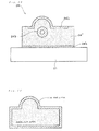
- the shrinkage phenomenon occurs when the molten powder is solidified due to a cooling thereof (see Fig. 2 (a) ) .
- a base plate for shaped object 21 which supports the solidified layer (i.e., three-dimensional shaped object), is a rigid body made of a steel material or the like and is distant from the position to be irradiated with the light beam. Therefore, the base plate for shaped object 21 is substantially less likely to be influenced by heat attributable to the light beam. As a result, an upward warping force (moment) is generated in the three-dimensional shaped object 24 on the base plate for shaped object. When this upward warping force exceeds a certain limit, there occurs a phenomenon in which the three-dimensional shaped object 24 peels from the base plate for shaped object 21 upon manufacturing, as shown in Fig. 2 (b) .
- the upward warp of the three-dimensional shaped object and the peeling thereof from the base plate are not desirable since it becomes difficult to manufacture a desired three-dimensional shaped object.
- the three-dimensional shaped object i.e., solidified layer
- it becomes impossible to newly provide a powder layer with a predetermined thickness on the solidified layer due to the upward warping of the solidified layer e.g., when the solidified layer warps upward to the extent more than the thickness of a powder layer to be newly provided
- a manufacturing method as described in JP-T-8-504139 has been proposed as the method in which consideration is made on shrinkage of a three-dimensional shaped object.
- a three-dimensional shaped object is manufactured so that an inner core portion and an outer shell portion are seperately formed (see Fig. 17 ). Since the outer shell portion has a solidified density higher than that of the inner core portion, a formation of the outer shell portion requires a high energy and also takes a longer time.
- consideration is not made on a final use application of the shaped object and the outer shell portion, and only forms a "shell" as its name suggests.
- the entire periphery of the three-dimensional shaped object is coated with a material with a generally uniform thickness (see Fig. 17 ) and it is by no means satisfactory from the viewpoint of the manufacturing cost and time.
- an object of the present invention is to provide a "method for manufacturing a three-dimensional shaped object" which not only prevents warp deformation of the resulting three-dimensional shaped object, but also enables more reduced manufacturing time and manufacturing cost.
- the present invention provides a method for manufacturing a three-dimensional shaped object, the method comprising the repeated steps of:
- the manufacturing method of the present invention is characterized in that the high-density portion is formed only at required position. More specifically, the high-density portion is formed only in a portion (in some cases, portion in the vicinity of the portion) of the three-dimensional shaped object, to which the force is applied when the three-dimensional shaped object is used.
- high-density portion refers to so-called " melting " (i.e., a portion formed by solidification after a substantially complete melting of a powder constituting a powder layer). That is, the term “high-density portion " substantially means a portion, through which a fluid such as liquid or gas does not pass, because of its very high solidified density (i.e., solidified density of about 95 to 100%).
- the term “force” means a force attributable to a pressure of a fluid or the like, a force attributable to contact, a force attributable to a friction force and the like.
- force substantially means a force applied to a three-dimensional shaped object when a resin material, cooling water, oil and/or steam are in contact with the three-dimensional shaped object.
- powder layer as used in this description and claims means, for example, "metal powder layer made of a metal powder” or "resin powder layer made of a resin powder”.
- predetermined portion of a powder layer substantially means a portion of a three-dimensional shaped obj ect to be manufactured. Therefore, a powder existing in such predetermined portion is irradiated with a light beam, whereby, the powder undergoes a sintering or a melting and subsequent solidification thereof to form a shape of a three-dimensional shaped object.
- solidifies laser substantially means “sintered layer” when the powder layer is a metal powder layer, whereas it substantially means “cured layer” when the powder layer is a resin powder layer.
- the solidified density of a high-density portion is about 95 to 100%, preferably 98% to 100%, and more preferably about 100% substantially. As the solidified density of the high-density portion becomes higher, there is provided a higher strength of the shaped object with respect to the force to be applied when the shaped obj ect is used. While on the other hand, the low-density portion may have any solidified density as long as the solidified density is 0 to 95% (excluding 95%) and the solidified density may be determined taking the function, manufacturing time, manufacturing cost and the like of the three-dimensional shaped object into consideration. For example, the low-density portion has the solidified density of 70 to 90%, and may in some cases have the solidified density lower than "70 to 90%".
- the high-density portion is formed in a part of the surface region of the three-dimensional shaped object. In other words, “melting” is formed only in such surface region, to which "force” is applied.
- the high-density portion may be formed in the portion which is in contact with the base plate for shaped object.
- At least one high-density portion 'c' may be formed in the interior portion of the three-dimensional shaped object such that "high-density portion 'a' formed in a part of the surface region" and "high-density portion 'b' formed in the portion which is in contact with the base plate for shaped object" are mutually connected.
- the high-density portion is formed in a part of the interior portion of the three-dimensional shaped object.
- a portion to which "force” is applied e.g., a wall portion of a cooling water channel of a metal mold
- such portion is configured to be “high-density portion"/"melting".
- the high-density portion is formed in the portion which would be a heat-transfer portion when the three-dimensional shaped obj ect is used.
- the surface, which is in contact with a substance having a high temperature or low temperature is configured to be "high-density portion"/"melting"
- the present invention also provides a three-dimensional shaped object obtained by the aforementioned manufacturing method.
- such three-dimensional shaped object can be used as a metal mold.
- a cavity-forming surface (i.e., wall surface in the interior of a metal mold which enables a formation of a molded article) of a metal mold corresponds to "high-density portion formed in a part of the surface region of the three-dimensional shaped object".
- a wall portion of a cooling water channel of the metal mold can correspond to "high-density portion formed in a part of the interior portion of the three-dimensional shaped object".
- the portion to which the force is applied when the metal mold is used may correspond to the "joint portion of a high-density portion 'a' and a high-density portion 'c' of the three-dimensional shaped object,".
- the high-density portion is formed only at required position, and thereby making it possible to shorten the manufacturing time and also to reduce the proportion of the high-density portion which essentially requires a high energy for the formation thereof. This leads to an achievement of the reduction of the manufacturing cost of the shaped object.
- the present invention can produce the three-dimensional shaped object with a percentage of the large shrinkage portion being kept as low as possible. This can contribute to a prevention or reduction of an upward warping of the three-dimensional shaped object, thus making it possible to prevent the three-dimensional shaped object (i.e., solidified layer) from peeling from the surface of the base plate. In other words, not only it becomes possible to newly provide a powder layer with a predetermined thickness on the solidified layer, but also a shape accuracy of the obtained three-dimensional shaped object is improved.
- the present invention is also very useful in that it is possible to suitably design the shaped object while preventing an increase in the manufacturing time and manufacturing cost in spite of those unpredictable phenomena.
- Fig. 1 , Fig. 3 and Fig. 4 show functions and constitutions, which enable execution of the selective laser sintering method, of a laser-sintering/milling hybrid machine 1.
- the laser-sintering/milling hybrid machine 1 is mainly provided with a "powder layer forming means 2 for forming a powder layer by providing a powder such as a metal powder or a resin powder in a predetermined thickness"; a "forming table 20 which is capable of vertically elevating/descending by cylinder drive in a forming tank 29 whose outer periphery is surrounded with a wall 27"; a "base plate for shaped object 21 which is disposed on the forming table 20 and serves as a platform of a shaped object”; a “laser-beam irradiation means 3 for irradiating an arbitrary position with an emitted light beam L" ; and a “milling means 4 for milling the periphery of a shaped object".
- the powder layer forming means 2 is mainly composed of a "powder table 25 capable of vertically elevating/descending by cylinder drive in a storage tank for powder material 28 whose outer periphery is surrounded with a wall 26" and a "squeegee blade 23 for forming a powder layer 22 on a base plate for shaped object".
- the laser-beam irradiation means 3 is mainly composed of a "light beam generator 30 for emitting a light beam L" and a "galvanometer mirror 31 (scan optical system) for scanning a light beam L onto a powder layer 22".
- the laser-beam irradiation means 3 is equipped with a beam shape correcting means for correcting a shape of a light beam spot (e.g., a means composed of a pair of cylindrical lens and a rotation drive mechanism for rotating the lens around a shaft line of the light beam) and f ⁇ lens.
- the milling means 4 is mainly composed of a "milling head 40 for milling the periphery of a shaped object" and an "X-Y actuator 41 (41a, 41b) for driving the milling head 40 to move toward the position to be milled (see Fig. 3 and Fig. 4 ).
- Fig. 5 shows an operation flow of a laser-sintering/milling hybrid machine.
- Fig. 6 schematically and simply shows a laser-sintering/milling hybrid process.
- the operations of the laser-sintering/milling hybrid machine are mainly composed of a powder layer forming step (S1) of forming a powder layer 22; a solidified layer forming step (S2) of irradiating the powder layer 22 with a light beam L to form a solidified layer 24; and a milling step (S3) of milling a surface of a shaped object.
- the powder layer forming step (S1) first, the forming table 20 is descended by ⁇ t1 (S11). Subsequently, a powder table 25 is elevated by ⁇ t1, and thereafter the squeegee blade 23 is driven to move in the direction of arrow A as shown in Fig. 1(a) .
- a powder e.g., an "iron powder having a mean particle diameter of about 5 ⁇ m to 100 ⁇ m” or a “powder having a mean particle diameter of about 30 ⁇ m to 100 ⁇ m, such as a powder of nylon, polypropylene or ABS” placed on the powder table 25 is spread to form a powder layer 2 in a predetermined thickness ⁇ t1 2 (S13), while being transferred onto the base plate 21 (S12).
- the solidified layer forming step (S2) is performed.
- a light beam L (e.g., carbon dioxide laser (500 W), Nd:YAG laser (500 W) or ultraviolet light) is emitted from the light beam generator 30 (S21) and then a light beam L is scanned onto an arbitrary position of the powder layer 22 by means of the galvanometer mirror 31 (S22) .
- the scanned light beam can cause the powder to be melted and solidified, resulting in a formation of the solidified layer 24 integrated with the base plate 21 (S23).
- the light beam may be transmitted by an optical fiber or the like.
- the powder layer forming step (S1) and the solidified layer forming step (S2) are repeatedly performed until the thickness of the stacked layers 24 reaches a predetermined value that is obtained based on a tool length of the milling head 40 (see Fig. 1(b) ).
- the solidified layer to be newly stacked is integrated with the lower solidified layer which has already been formed upon a sintering of the powder or a melting and subsequent solidification of the powder.
- a milling means to be used in the milling step may be a general-purpose numerical control (NC) machine tool or those analogous thereto. Particularly, a machining center (MC) capable of automatically replacing a milling tool (end mill) is preferred. As the end mill, a twin-bladed type ball end mill made of a superhard material may be mainly used. A square end mill, a radius end mill, drill or the like may also be used according to an intended shape or an object. In the embodiments as shown in Fig. 1 and Fig. 6 , the milling head 40 is actuated to initiate execution of the milling step (S31).
- NC numerical control
- MC machining center
- end mill a twin-bladed type ball end mill made of a superhard material may be mainly used.
- a square end mill, a radius end mill, drill or the like may also be used according to an intended shape or an object.
- the milling head 40 is actuated to initiate execution of the milling step (S31).
- the milling head 40 is actuated when sixty solidified layers are formed.
- the milling head 40 is moved in X and Y directions by means of the X-Y actuator 41 (41a, 41b) and the surface of the shaped object composed of stacked solidified layers 24 is subjected to milling (S32).
- the step returns to the powder layer forming step (S1). Thereafter, the steps S1 through S3 are repeatedly performed to further stack the solidified layers 24, and thereby making it possible to manufacture the desired three-dimensional shaped object (see Fig. 6 ).
- An irradiation path of the light beam L in the solidified layer forming step (S2) and a milling path in the milling step (S3) are determined in advance using 3-D CAD data.
- the machining path is determined by applying contour line processing.
- the contour shape data of each of sliced sections which are regularly-pitched (e.g., 0.05 mm pitch when ⁇ t1 is 0.05 mm) sliced sections of STL data produced from a 3-D CAD model, are used.
- the manufacturing method of the present invention particularly takes into consideration applications (i.e., intended end-usage) of the three-dimensional shaped object obtained from the aforementioned selective laser sintering method.
- the present invention is characterized in that the solidified layer is formed such that the surface to which a force is applied when the three-dimensional shaped object is used becomes "melting".
- the solidified layer is formed such that the "surface which is in contact with the other substance when the three-dimensional shaped object is used" becomes “melting”.
- the present invention will be described by way of an embodiment using a “metal powder” as the powder.
- the "embodiment using a metal powder” corresponds to an "embodiment using a metal powder layer as a powder layer”.
- the metal powder used in the present invention may be a powder containing an iron based powder as a main component, and may be a powder which further contains at least one kind selected from the group consisting of a nickel powder, a nickel based alloy powder, a copper powder, a copper based alloy powder and a graphite powder in some cases.
- the metal powder examples include a metal powder in which the proportion of an iron based powder having a mean particle diameter of about 20 ⁇ m is 60 to 90% by weight, the proportion of both or either of a nickel powder and a nickel based alloy powder is 5 to 35% by weight, the proportion of both or either of a copper powder and/or a copper based alloy powder is 5 to 15% by weight, and the proportion of a graphite powder is 0.2 to 0.8% by weight.
- the solidified layers are formed such that a portion thereof to which a force P is applied when the three-dimensional shaped object 24 is used corresponds to a high-density portion 24' whose solidified density is 95 to 100% and the other portion thereof corresponds to a low-density portion 24" whose solidified density is 0 to 95% (excluding 95%). It is particularly preferred to form the high-density portion (i.e., high-density melting) by completely melting the powder in the predetermined portion through the irradiation thereof with the light beam. Fig.
- FIG. 8 shows a SEM photograph of the boundary portion between the high-density portion and the low-density portion formed according to the manufacturing method of the present invention.
- Fig. 9 shows the respective sectional photographs (SEM photographs) of the high-density portion and the low-density portion.
- the complete melting of the powder may be allowed to occur by increasing an output energy of the light beam for irradiation. While on the other hand, in order to form the low-density portion, the complete melting of the powder may not be allowed to occur by decreasing the output energy of the light beam for irradiation.
- the aforementioned operations (a) to (d) may be performed alone, or performed in combination.
- the high-density portion whose solidified density is 95 to 100% can be formed by adjusting an irradiation energy density E of the light beam in a range from about 4 to 15 J/mm 2 .
- it is also possible to form the low-density portion by (a) decreasing of the output energy of the light beam, (b) increasing a scanning rate of the light beam, (c) enlarging a scanning pitch of the light beam and (d) increasing a condensing diameter of the light beam.
- the low-density portion whose solidified density is 70 to 90% can be formed by adjusting the irradiation energy density E of the light beam in a range from about 1 to 3 J/mm 2 .
- 3-D CAD data of the laser-sintering/milling hybrid machine two models, for example, a 3-D CAD model A of the high-density portion and a 3-D CAD model B of the low-density portion are prepared and the respective conditions are designated by assigning a role, and also a coordinate system defining where each model is formed is adjusted.
- a coordinate system defining where each model is formed is adjusted.
- An irradiation path of the light beam is made from data of a 3-D CAD model in advance and the contour shape data of each of sliced sections, which are regularly-pitched (e.g., 0.05 mm) sliced sections of STL data produced from the 3-D CAD model, are used.
- the 3-D CAD model is divided in advance into a portion which would serve as the high-density portion, and a portion which would serve as the low-density portion.
- the contour shape data of each of sliced sections for the portion which would serve as the high-density portion, and the portion which would serve as the low-density portion are made, and a powder material is subjected to a sintering or a melting and subsequent solidification thereof by irradiating with the light beam at each portion by using of such data.
- the high-density portion is a "dense portion" through which a fluid such as liquid or gas cannot pass. More specifically, the high-density portion can be a portion through which a fluid cannot pass under the condition when the shaped object is used.
- the solidified density is in the range of 95 to 100%, preferably in the range of 98% to 100%, and more preferably substantially about 100%. As the solidified density of the high-density portion becomes higher, there is provided a high drag force with respect to a force to be applied to the three-dimensional shaped object, the force being due to a resin, cooling water, oil and/or steam.
- the high-density portion can have various geometries depending on the use of the three-dimensional shaped object (particularly depending on a form of the force which would be applied when the shaped object is used).
- the thickness may be uniform (e.g., about 0.01 mm to 10 mm) as shown in Fig. 7 .
- the thickness of the high-density portion 24' is not limited to "uniform", and may be "un-uniform”. Irrespective of "uniform thickness" or "un-uniform thickness” , the thickness of the high-density portion may be varied depending on the intended function of the three-dimensional shaped object.
- the solidified density of the low-density portion 24" (e.g., see Fig. 7 ) is 0 to 95% (not including 95%) and the low-density portion is a "coarse portions".
- the solidified density of the low-density portion may be finally determined taking the function, manufacturing time, manufacturing cost and the like of the three-dimensional shaped object into consideration.
- the solidified density of the low-density portion may be, for example, 70 to 90%, and may be lower than such range in some cases.
- the solidified density may be 0%. This means that irradiation with the light beam is not particularly necessary for the formation of the low-density portion.
- the term " solidified density" substantially means a sintered sectional density (occupation ratio of a metallic material) determined by image processing of a sectional photograph of the shaped object.
- Image processing software for determining the sintered sectional density is Scion Image ver. 4.0.2 (freeware).
- a sintered sectional density ⁇ s from the below-mentioned equation 1 by binarizing a sectional image into a sintered portion (white) and a vacancy portion (black), and then counting all picture element numbers Px all of the image and picture element number Px white of the sintered portion (white).
- the solidified layers are formed such that a portion thereof to which a force is applied when the three-dimensional shaped object is used consists of the high-density portion whose solidified density is 95 to 100% and the other portion consists of the low-density portion whose solidified density is 0 to 95% (excluding 95%)" are as follows ("metal powder” is used as the powder by way of example);
- the embodiment of "high-density portion formed in a part of a surface of the shaped object” is shown in Fig. 10 .
- the high-density portion 24'a is formed only at a surface region of the three-dimensional shaped object 24, to which a force P is applied when the shaped object 24 is used.
- the high-density portion formed in a part of the surface region of the shaped object can correspond to an inner surface of the metal mold (i.e., a molded surface which constitutes a cavity space).
- the solidified density of the high-density portion is preferably in the range of about 98% to 100%, and the thickness Ta (see Fig. 10 ) of the high-density portion is preferably in the range of about 0.5 to 5 mm. While on the other hand, the solidified density of the low-density portion 24" is preferably in the range of about 70 to 90%.
- Fig. 11 The embodiment of "high-density portion formed at a surface boundary with respect to a surface of a base plate for shaped object" is shown in Fig. 11 .
- the high-density portion 24'b may be formed in the portion which is in contact with the base plate for shaped object 21.
- the joint strength is increased by applying a higher energy to the joint portion, thereby configuring to be "melting".
- the solidified density of the high-density portion 24'b is preferably in the range of 98% to 100%, and the thickness Tb (see Fig. 11 ) of the high-density portion 24'b may be comparatively thin and thus is preferably in the range of about 0.05 to 0.3 mm. While on the other hand, the solidified density of the low-density portion 24" is preferably in the range of about 70 to 90%.
- the high-density portion can be formed in not only the portion 24'b which is in contact with the base plate for shaped obj ect, but also the portion 24' a which corresponds to a cavity-forming surface of the metal mold (see Fig. 11 ).
- Fig. 12 or Fig. 13 The embodiment of "cell structure or truss structure" is shown in Fig. 12 or Fig. 13 .
- at least one high-density portion 'c' (24'c) may be formed in the interior portion of the three-dimensional shaped object such that the "high-density portion 'a' (24'a) formed in a part of the surface region of the shaped object," and the "high-density portion 'b' (24'b) formed in the portion of the shaped object, the portion being in contact with the base plate" are connected to each other.
- the high-density portion 'c' can function as a reinforced portion.
- such local portion is provided as "joint portion between the high-density portion 'a' (24'a) and the high-density portion 'c' (24'c)".
- a high-density portion 24'd is formed only in interior portion of the three-dimensional shaped object 24, to which a force P is applied when the shaped object is used.
- the high-density portion 24'd formed in a part of the interior portion can correspond to a wall of a cooling water channel of the metal mold.
- a fluid pressure (“hydraulic pressure") attributable to the cooling water is generated.
- the solidified density of the high-density portion 24'd is preferably in the range of about 98% to 100%, and the thickness Tc (see Fig. 15 ) of the high-density portion 24'd is preferably increased, comparatively, and thus is preferably in the range of about 2 to 5 mm. While on the other hand, the solidified density of the low-density portion 24" is preferably in the range of about 70 to 90%.
- the high-density portion is formed in not only the interior portion 24'd of the shaped object, but also the "portion 24'a of the shaped object, the portion 24'a corresponding to a cavity-forming surface of the metal mold" and the "portion 24'b which is in contact with the base plate for shaped object" (see Fig. 16 ).
- a high-density portion is formed only in the portion corresponding to a heat transfer portion when a three-dimensional shaped obj ect is used.
- the high-density portion has not only high strength, but also high thermal conductivity, and thereby providing an effective thermal efficiency. For example, when the high-density portion corresponds to a wall of a cooling water channel 24'd of a metal mold (see Fig.
- the first aspect A method for manufacturing a three-dimensional shaped object, the method comprising the repeated steps of:
- the method for manufacturing a three-dimensional shaped object according to present invention can produce various kinds of objects.
- the powder layer is a metal powder layer (inorganic powder layer) and thus the solidified layer corresponds to a sintered layer
- the produced three-dimensional shaped object can be used as a metal mold for a plastic injection molding, a press molding, a die casting, a casting or a forging.
- the produced three-dimensional shaped object can be used as a resin molded part.
Abstract
Description
- The present invention relates to a method for manufacturing a three-dimensional shaped object, and also relates to the three-dimensional shaped object. More particularly, the present invention relates to a method for manufacturing a three-dimensional shaped object with a plurality of solidified layers stacked integrally by repeating the step of forming a solidified layer by irradiating a predetermined portion of a powder layer with a light beam, and also relates to the three-dimensional shaped object obtained by such manufacturing method.
- Heretofore, a method for manufacturing a three-dimensional shaped object by irradiating a powder with a light beam has been known (such method can be generally referred to as a "selective laser sintering method"). Such method can produce a three-dimensional shaped object with a plurality of solidified layers stacked integrally by repeating the step (i) of forming a solidified layer by irradiating a predetermined portion of a powder layer with a light beam, thereby allowing sintering of the predetermined portion of the powder or melting and subsequent solidification thereof, and the step (ii) of forming another solidified layer by newly forming a powder layer on the resulting solidified layer, followed by similarly irradiating the powder layer with the light beam (see
JP-T-01-502890 JP-A-2000-73108 - According to the selective laser sintering method, a three-dimensional shaped object is often manufactured in a chamber maintained under an inert atmosphere from the viewpoint of the prevention of oxidation or the like. By way of the case of using a metal powder as a powder material and using the resulting three-dimensional shaped object as metal mold, as shown in
Fig. 1 , apowder layer 22 with a predetermined thickness tl is firstly formed on a base plate for shaped object 21 (see Fig. 1(a)) and then a predetermined portion of apowder layer 22 is irradiated with a light beam to form asolidified layer 24 on base plate forshaped object 21. Then, apowder layer 22 is newly provided on thesolidified layer 24 thus formed and is irradiated again with the light beam to form another solidified layer. In this way, when the solidified layer is repeatedly formed, it is possible to obtain a three-dimensional shaped object with a plurality ofsolidified layers 24 stacked integrally (seeFig. 1(b) ). The solidified layer corresponding to a bottom layer can be formed in a state of being adhered to the surface of the base plate for shaped object. Therefore, the three-dimensional shaped object and the base plate for shaped object are mutually integrated. The integrated "three-dimensional shaped object" and "base plate for shaped object" can be used as a metal mold as they are. - Herein, the three-dimensional shaped object is manufactured by irradiation with a light beam and is therefore considerably influenced by heat attributable to the light beam. Specifically, the portion to be irradiated of the powder layer is once melted to become a molten state, and then a solidified layer is formed when such portion is solidified. However, a shrinkage phenomenon can occur upon the solidification. In particular, the shrinkage phenomenon occurs when the molten powder is solidified due to a cooling thereof (see
Fig. 2 (a) ) . While on the other hand, a base plate forshaped object 21, which supports the solidified layer (i.e., three-dimensional shaped object), is a rigid body made of a steel material or the like and is distant from the position to be irradiated with the light beam. Therefore, the base plate forshaped object 21 is substantially less likely to be influenced by heat attributable to the light beam. As a result, an upward warping force (moment) is generated in the three-dimensionalshaped object 24 on the base plate for shaped object. When this upward warping force exceeds a certain limit, there occurs a phenomenon in which the three-dimensionalshaped object 24 peels from the base plate forshaped object 21 upon manufacturing, as shown inFig. 2 (b) . The upward warp of the three-dimensional shaped object and the peeling thereof from the base plate are not desirable since it becomes difficult to manufacture a desired three-dimensional shaped object. For example, when the three-dimensional shaped object (i.e., solidified layer) warps upward, it becomes impossible to achieve a shape accuracy of the resulting three-dimensional shaped object. Also, when it becomes impossible to newly provide a powder layer with a predetermined thickness on the solidified layer due to the upward warping of the solidified layer (e.g., when the solidified layer warps upward to the extent more than the thickness of a powder layer to be newly provided), it will become impossible to uniformly provide the new powder layer by the squeegee process. - A manufacturing method as described in
JP-T-8-504139 Fig. 17 ). Since the outer shell portion has a solidified density higher than that of the inner core portion, a formation of the outer shell portion requires a high energy and also takes a longer time. In the invention ofJP-T-8-504139 JP-T-8-504139 Fig. 17 ) and it is by no means satisfactory from the viewpoint of the manufacturing cost and time. - Under these circumstances, the present invention has been created. That is, an object of the present invention is to provide a "method for manufacturing a three-dimensional shaped object" which not only prevents warp deformation of the resulting three-dimensional shaped object, but also enables more reduced manufacturing time and manufacturing cost.
- In order to achieve the above object, the present invention provides a method for manufacturing a three-dimensional shaped object, the method comprising the repeated steps of:
- (i) forming a solidified layer by irradiating a predetermined portion of a powder layer on a base plate for shape object with a light beam (for example, a directional energy beam such as laser beam), thereby allowing sintering of the powder in the predetermined portion or melting and subsequent solidification thereof; and
- (ii) forming another solidified layer by newly forming a powder layer on the resulting solidified layer, followed by the irradiation of a predetermined portion of the powder layer with the light beam;
- For one thing, the manufacturing method of the present invention is characterized in that the high-density portion is formed only at required position. More specifically, the high-density portion is formed only in a portion (in some cases, portion in the vicinity of the portion) of the three-dimensional shaped object, to which the force is applied when the three-dimensional shaped object is used.
- As used in this description and claims, the term "high-density portion" refers to so-called "melting" (i.e., a portion formed by solidification after a substantially complete melting of a powder constituting a powder layer). That is, the term "high-density portion" substantially means a portion, through which a fluid such as liquid or gas does not pass, because of its very high solidified density (i.e., solidified density of about 95 to 100%).
- As used in this description and claims, the term "force" means a force attributable to a pressure of a fluid or the like, a force attributable to contact, a force attributable to a friction force and the like. For example, the term "force" substantially means a force applied to a three-dimensional shaped object when a resin material, cooling water, oil and/or steam are in contact with the three-dimensional shaped object.
- Describing just for confirmation, the term "powder layer" as used in this description and claims means, for example, "metal powder layer made of a metal powder" or "resin powder layer made of a resin powder". Also, the term "predetermined portion of a powder layer" substantially means a portion of a three-dimensional shaped obj ect to be manufactured. Therefore, a powder existing in such predetermined portion is irradiated with a light beam, whereby, the powder undergoes a sintering or a melting and subsequent solidification thereof to form a shape of a three-dimensional shaped object. The term "solidifies laser" substantially means "sintered layer" when the powder layer is a metal powder layer, whereas it substantially means "cured layer" when the powder layer is a resin powder layer.
- The solidified density of a high-density portion is about 95 to 100%, preferably 98% to 100%, and more preferably about 100% substantially. As the solidified density of the high-density portion becomes higher, there is provided a higher strength of the shaped object with respect to the force to be applied when the shaped obj ect is used. While on the other hand, the low-density portion may have any solidified density as long as the solidified density is 0 to 95% (excluding 95%) and the solidified density may be determined taking the function, manufacturing time, manufacturing cost and the like of the three-dimensional shaped object into consideration. For example, the low-density portion has the solidified density of 70 to 90%, and may in some cases have the solidified density lower than "70 to 90%".
- In one preferred embodiment, the high-density portion is formed in a part of the surface region of the three-dimensional shaped object. In other words, "melting" is formed only in such surface region, to which "force" is applied. When the three-dimensional shaped object integrated with the base plate for shaped obj ect is used as the product without being separated from each other, the high-density portion may be formed in the portion which is in contact with the base plate for shaped object. In such case, at least one high-density portion 'c' may be formed in the interior portion of the three-dimensional shaped object such that "high-density portion 'a' formed in a part of the surface region" and "high-density portion 'b' formed in the portion which is in contact with the base plate for shaped object" are mutually connected.
- In another preferred embodiment, the high-density portion is formed in a part of the interior portion of the three-dimensional shaped object. In other words, when a portion to which "force" is applied (e.g., a wall portion of a cooling water channel of a metal mold) is provided in the inner portion of the shaped object, such portion is configured to be "high-density portion"/"melting".
- In still another preferred embodiment, the high-density portion is formed in the portion which would be a heat-transfer portion when the three-dimensional shaped obj ect is used. In other words, the surface, which is in contact with a substance having a high temperature or low temperature, is configured to be "high-density portion"/"melting",
- The present invention also provides a three-dimensional shaped object obtained by the aforementioned manufacturing method. In particularly preferred embodiment, such three-dimensional shaped object can be used as a metal mold. A cavity-forming surface (i.e., wall surface in the interior of a metal mold which enables a formation of a molded article) of a metal mold corresponds to "high-density portion formed in a part of the surface region of the three-dimensional shaped object". Also, a wall portion of a cooling water channel of the metal mold can correspond to "high-density portion formed in a part of the interior portion of the three-dimensional shaped object". Furthermore, the portion to which the force is applied when the metal mold is used may correspond to the "joint portion of a high-density portion 'a' and a high-density portion 'c' of the three-dimensional shaped object,".
- In accordance with the present invention, the high-density portion is formed only at required position, and thereby making it possible to shorten the manufacturing time and also to reduce the proportion of the high-density portion which essentially requires a high energy for the formation thereof. This leads to an achievement of the reduction of the manufacturing cost of the shaped object.
- According to the manufacturing method of the present invention, there is provided a reduced proportion of the high-density portion in the entire three-dimensional shaped object, since the high-density portion is formed only at required position. Therefore, in light of the fact that the high-density portion is considered "portion where a shrinkage ratio is comparatively large due to a cooling and subsequent solidification of the molten powder" , the present invention can produce the three-dimensional shaped object with a percentage of the large shrinkage portion being kept as low as possible. This can contribute to a prevention or reduction of an upward warping of the three-dimensional shaped object, thus making it possible to prevent the three-dimensional shaped object (i.e., solidified layer) from peeling from the surface of the base plate. In other words, not only it becomes possible to newly provide a powder layer with a predetermined thickness on the solidified layer, but also a shape accuracy of the obtained three-dimensional shaped object is improved.
- Furthermore, it was inevitably required in the prior art to design on preliminary assumption of phenomena such as "upward warping" and "peeling" in order to achieve the shape accuracy of the three-dimensional shaped object. However, it is possible according to the present invention to prevent "upward warping" and "peeling" while reducing the manufacturing time and manufacturing cost only by providing the high-density portion at a required position of the shaped object. In other words, the present invention is also very useful in that it is possible to suitably design the shaped object while preventing an increase in the manufacturing time and manufacturing cost in spite of those unpredictable phenomena.
-
-
Fig. 1 is a sectional view schematically showing operations of a laser-sintering/milling hybrid machine. -
Fig. 2 is a sectional view schematically showing a phenomenon which causes an upward warping or peeling of a three-dimensional shaped object. -
Fig. 3 is a perspective view schematically showing an embodiment in which a selective laser sintering method is carried out. -
Fig. 4 is a perspective view schematically showing a constitution of a laser-sintering/milling hybrid machine by which a selective laser sintering method is carried out. -
Fig. 5 is a flow chart of operations of a laser-sintering/milling hybrid machine. -
Fig. 6 is a schematic view showing a laser-sintering/milling hybrid process with a lapse of time. -
Fig. 7 is a schematic view schematically showing a feature of a three-dimensional shaped object obtained by the manufacturing method of the present invention. -
Fig. 8 is a SEM photograph (sectional photograph in a broken line portion ofFig. 7 ) of a three-dimensional shaped object obtained by the manufacturing method of the present invention. -
Fig. 9 is SEM photographs (sectional photograph of a three-dimensional shaped object) of a high-density portion (melting) and a low-density portion. -
Fig. 10 is a schematic view showing an embodiment of a high-density portion formed in a part of a surface of a shaped object. -
Fig. 11 is a schematic view showing an embodiment of a high-density portion formed at the surface boundary with respect to a surface of base plate for shaped object. -
Fig. 12 is a schematic view showing an embodiment of a high-density portion formed such that a shaped object has a cell structure or a truss structure. -
Fig. 13 is a perspective view of three-dimensional shaped object, which schematically shows an embodiment of a cell structure. -
Fig. 14 is a schematic view showing an embodiment, showing a high-density portion formed such that a shaped object has a cell structure or a truss structure, wherein the position to which a force is applied is reinforced. -
Fig. 15 is a schematic view showing an embodiment of a high-density portion formed in a part of the interior of a shaped object. -
Fig. 16 is a schematic view showing a typical embodiment of a three-dimensional shaped object (metal mold) integrated with a base plate for shaped object. -
Fig. 17 is a schematic view showing an embodiment of a three-dimensional shaped object of the prior art (JP-T-8-504139 - 1 Laser-sintering/milling hybrid machine
- 2 Powder layer forming means
- 3 Laser-beam irradiation means
- 4 Milling means
- 19 Powder/powder layer (e.g., metal powder/metal powder layer or resin powder/resin powder layer)
- 20 Forming table
- 21 Base plate for shaped object
- 22 Powder layer (e.g., metal powder layer or resin powder layer)
- 23 Squeegee blade
- 24 Solidified layer (e.g., sintered layer or cured layer) or three-dimensional shaped object obtained therefrom
- 24' High-density portion (high-density melting)
- 24' a High-density portion (high-density melting, for example "cavity-forming surface of metal mold")
- 24'b High-density portion (high-density melting, for example "high-density portion formed at the surface boundary with respect to plate")
- 24'c High-density portion (high-density melting, for example "high-density portion having cell structure or truss structure")
- 24'd High-density portion (high-density melting, for example "wall of cooling water channel of metal mold")
- 24" Low-density portion
- 25 Powder table
- 26 Wall of storage tank for powder material
- 27 Wall of forming tank
- 28 Storage tank for powder material
- 29 Forming tank
- 30 Light beam generator
- 31 Galvanometer mirror
- 32 Reflecting mirror
- 33 Collecting lens
- 40 Milling head
- 41 X-Y actuator
- 41a X-axis actuator
- 41b Y-axis actuator
- 42 Tool magazine
- 50 Chamber
- 52 Window for transmission of light
- L Light beam
- p "Force" applied to three-dimensional shaped object in use
- The present invention will be hereinafter described in more detail with reference to the accompanying drawings.
- First, a selective laser sintering method, on which the manufacturing method of the present invention is premised, will be described.
Fig. 1 ,Fig. 3 andFig. 4 show functions and constitutions, which enable execution of the selective laser sintering method, of a laser-sintering/millinghybrid machine 1. The laser-sintering/millinghybrid machine 1 is mainly provided with a "powderlayer forming means 2 for forming a powder layer by providing a powder such as a metal powder or a resin powder in a predetermined thickness"; a "forming table 20 which is capable of vertically elevating/descending by cylinder drive in a formingtank 29 whose outer periphery is surrounded with awall 27"; a "base plate for shapedobject 21 which is disposed on the forming table 20 and serves as a platform of a shaped object"; a "laser-beam irradiation means 3 for irradiating an arbitrary position with an emitted light beam L" ; and a "milling means 4 for milling the periphery of a shaped object". As shown inFig. 1 , the powderlayer forming means 2 is mainly composed of a "powder table 25 capable of vertically elevating/descending by cylinder drive in a storage tank forpowder material 28 whose outer periphery is surrounded with awall 26" and a "squeegee blade 23 for forming apowder layer 22 on a base plate for shaped object". As shown inFig. 3 andFig. 4 , the laser-beam irradiation means 3 is mainly composed of a "light beam generator 30 for emitting a light beam L" and a "galvanometer mirror 31 (scan optical system) for scanning a light beam L onto apowder layer 22". If necessary, the laser-beam irradiation means 3 is equipped with a beam shape correcting means for correcting a shape of a light beam spot (e.g., a means composed of a pair of cylindrical lens and a rotation drive mechanism for rotating the lens around a shaft line of the light beam) and fθ lens. The milling means 4 is mainly composed of a "millinghead 40 for milling the periphery of a shaped object" and an "X-Y actuator 41 (41a, 41b) for driving the millinghead 40 to move toward the position to be milled (seeFig. 3 andFig. 4 ). - Operations of the laser-sintering/milling
hybrid machine 1 will be described in detail with reference toFig. 1 ,Fig. 5 andFig. 6 .Fig. 5 shows an operation flow of a laser-sintering/milling hybrid machine.Fig. 6 schematically and simply shows a laser-sintering/milling hybrid process. - The operations of the laser-sintering/milling hybrid machine are mainly composed of a powder layer forming step (S1) of forming a
powder layer 22; a solidified layer forming step (S2) of irradiating thepowder layer 22 with a light beam L to form a solidifiedlayer 24; and a milling step (S3) of milling a surface of a shaped object. In the powder layer forming step (S1), first, the forming table 20 is descended by Δt1 (S11). Subsequently, a powder table 25 is elevated by Δt1, and thereafter thesqueegee blade 23 is driven to move in the direction of arrow A as shown inFig. 1(a) . Whereby, a powder (e.g., an "iron powder having a mean particle diameter of about 5 µm to 100 µm" or a "powder having a mean particle diameter of about 30 µm to 100 µm, such as a powder of nylon, polypropylene or ABS" placed on the powder table 25 is spread to form apowder layer 2 in a predetermined thickness Δt1 2 (S13), while being transferred onto the base plate 21 (S12). Following this step, the solidified layer forming step (S2) is performed. In this the solidified layer forming step, a light beam L (e.g., carbon dioxide laser (500 W), Nd:YAG laser (500 W) or ultraviolet light) is emitted from the light beam generator 30 (S21) and then a light beam L is scanned onto an arbitrary position of thepowder layer 22 by means of the galvanometer mirror 31 (S22) . The scanned light beam can cause the powder to be melted and solidified, resulting in a formation of the solidifiedlayer 24 integrated with the base plate 21 (S23). There is not limitation on transmission of the light beam in air, and the light beam may be transmitted by an optical fiber or the like. - The powder layer forming step (S1) and the solidified layer forming step (S2) are repeatedly performed until the thickness of the
stacked layers 24 reaches a predetermined value that is obtained based on a tool length of the milling head 40 (seeFig. 1(b) ). The solidified layer to be newly stacked is integrated with the lower solidified layer which has already been formed upon a sintering of the powder or a melting and subsequent solidification of the powder. - When the thickness of the stacked solidified
layers 24 reaches a predetermined thickness, the milling step (S3) is initiated. A milling means to be used in the milling step may be a general-purpose numerical control (NC) machine tool or those analogous thereto. Particularly, a machining center (MC) capable of automatically replacing a milling tool (end mill) is preferred. As the end mill, a twin-bladed type ball end mill made of a superhard material may be mainly used. A square end mill, a radius end mill, drill or the like may also be used according to an intended shape or an object. In the embodiments as shown inFig. 1 andFig. 6 , the millinghead 40 is actuated to initiate execution of the milling step (S31). For example, in a case where the tool (ball end mill) of the millinghead 40 has a diameter of 1 mm and an effective milling length of 3 mm, a milling in a depth of 3 mm can be performed. Therefore, when Δ1 is 0.05 mm, the millinghead 40 is actuated when sixty solidified layers are formed. The millinghead 40 is moved in X and Y directions by means of the X-Y actuator 41 (41a, 41b) and the surface of the shaped object composed of stacked solidifiedlayers 24 is subjected to milling (S32). When the entire three-dimensional shaped object has not yet been manufactured, the step returns to the powder layer forming step (S1). Thereafter, the steps S1 through S3 are repeatedly performed to further stack the solidified layers 24, and thereby making it possible to manufacture the desired three-dimensional shaped object (seeFig. 6 ). - An irradiation path of the light beam L in the solidified layer forming step (S2) and a milling path in the milling step (S3) are determined in advance using 3-D CAD data. In this case, the machining path is determined by applying contour line processing. For example, in the solidified layer forming step (S2), the contour shape data of each of sliced sections, which are regularly-pitched (e.g., 0.05 mm pitch when Δt1 is 0.05 mm) sliced sections of STL data produced from a 3-D CAD model, are used.
- The manufacturing method of the present invention particularly takes into consideration applications (i.e., intended end-usage) of the three-dimensional shaped object obtained from the aforementioned selective laser sintering method. Specifically, the present invention is characterized in that the solidified layer is formed such that the surface to which a force is applied when the three-dimensional shaped object is used becomes "melting". In other words, the solidified layer is formed such that the "surface which is in contact with the other substance when the three-dimensional shaped object is used" becomes "melting".
- In the following description, the present invention will be described by way of an embodiment using a "metal powder" as the powder. The "embodiment using a metal powder" corresponds to an "embodiment using a metal powder layer as a powder layer". By the way, the metal powder used in the present invention may be a powder containing an iron based powder as a main component, and may be a powder which further contains at least one kind selected from the group consisting of a nickel powder, a nickel based alloy powder, a copper powder, a copper based alloy powder and a graphite powder in some cases. Examples of the metal powder include a metal powder in which the proportion of an iron based powder having a mean particle diameter of about 20 µm is 60 to 90% by weight, the proportion of both or either of a nickel powder and a nickel based alloy powder is 5 to 35% by weight, the proportion of both or either of a copper powder and/or a copper based alloy powder is 5 to 15% by weight, and the proportion of a graphite powder is 0.2 to 0.8% by weight.
- In the manufacturing method of the present invention, as shown in
Fig. 7 , the solidified layers are formed such that a portion thereof to which a force P is applied when the three-dimensionalshaped object 24 is used corresponds to a high-density portion 24' whose solidified density is 95 to 100% and the other portion thereof corresponds to a low-density portion 24" whose solidified density is 0 to 95% (excluding 95%). It is particularly preferred to form the high-density portion (i.e., high-density melting) by completely melting the powder in the predetermined portion through the irradiation thereof with the light beam.Fig. 8 shows a SEM photograph of the boundary portion between the high-density portion and the low-density portion formed according to the manufacturing method of the present invention.Fig. 9 shows the respective sectional photographs (SEM photographs) of the high-density portion and the low-density portion. - In order to form the high-density portion, the complete melting of the powder may be allowed to occur by increasing an output energy of the light beam for irradiation. While on the other hand, in order to form the low-density portion, the complete melting of the powder may not be allowed to occur by decreasing the output energy of the light beam for irradiation. In addition to (a) increasing of output energy of the light beam, it is also possible to form the high-density portion by (b) lowering a scanning rate of the light beam, (c) narrowing scanning pitch of the light beam, and (d) decreasing a condensing diameter of the light beam. The aforementioned operations (a) to (d) may be performed alone, or performed in combination. Especially with respect to the aforementioned operation (a) for example, the high-density portion whose solidified density is 95 to 100% can be formed by adjusting an irradiation energy density E of the light beam in a range from about 4 to 15 J/mm2. Similarly, it is also possible to form the low-density portion by (a) decreasing of the output energy of the light beam, (b) increasing a scanning rate of the light beam, (c) enlarging a scanning pitch of the light beam and (d) increasing a condensing diameter of the light beam. For example, the low-density portion whose solidified density is 70 to 90% can be formed by adjusting the irradiation energy density E of the light beam in a range from about 1 to 3 J/mm2.
- With respect to the 3-D CAD data of the laser-sintering/milling hybrid machine, two models, for example, a 3-D CAD model A of the high-density portion and a 3-D CAD model B of the low-density portion are prepared and the respective conditions are designated by assigning a role, and also a coordinate system defining where each model is formed is adjusted. In other words, when the density and strength of three-dimensional shaped object are varied, it becomes possible to vary the density and strength by dividing the model into corresponding sites in advance, using 3-D CAD or the like, and setting light beam irradiation conditions with respect to each model. This is more specifically mentioned as follows: An irradiation path of the light beam is made from data of a 3-D CAD model in advance and the contour shape data of each of sliced sections, which are regularly-pitched (e.g., 0.05 mm) sliced sections of STL data produced from the 3-D CAD model, are used. When the high-density portion and the low-density portion are formed, the 3-D CAD model is divided in advance into a portion which would serve as the high-density portion, and a portion which would serve as the low-density portion. Then, the contour shape data of each of sliced sections for the portion which would serve as the high-density portion, and the portion which would serve as the low-density portion are made, and a powder material is subjected to a sintering or a melting and subsequent solidification thereof by irradiating with the light beam at each portion by using of such data.
- The high-density portion is a "dense portion" through which a fluid such as liquid or gas cannot pass. More specifically, the high-density portion can be a portion through which a fluid cannot pass under the condition when the shaped object is used. In such high-density portion, the solidified density is in the range of 95 to 100%, preferably in the range of 98% to 100%, and more preferably substantially about 100%. As the solidified density of the high-density portion becomes higher, there is provided a high drag force with respect to a force to be applied to the three-dimensional shaped object, the force being due to a resin, cooling water, oil and/or steam. The high-density portion can have various geometries depending on the use of the three-dimensional shaped object (particularly depending on a form of the force which would be applied when the shaped object is used). For example, when the high-density portion 24' has the form as shown in
Fig. 7 , the thickness may be uniform (e.g., about 0.01 mm to 10 mm) as shown inFig. 7 . However, the thickness of the high-density portion 24' is not limited to "uniform", and may be "un-uniform". Irrespective of "uniform thickness" or "un-uniform thickness" , the thickness of the high-density portion may be varied depending on the intended function of the three-dimensional shaped object. While on the other hand, the solidified density of the low-density portion 24" (e.g., seeFig. 7 ) is 0 to 95% (not including 95%) and the low-density portion is a "coarse portions". The solidified density of the low-density portion may be finally determined taking the function, manufacturing time, manufacturing cost and the like of the three-dimensional shaped object into consideration. The solidified density of the low-density portion may be, for example, 70 to 90%, and may be lower than such range in some cases. For example, when the shaped object with a cell structure or truss structure (which will be described below) is manufactured, the solidified density may be 0%. This means that irradiation with the light beam is not particularly necessary for the formation of the low-density portion. - As used in this description and claims, the term "solidified density" substantially means a sintered sectional density (occupation ratio of a metallic material) determined by image processing of a sectional photograph of the shaped object. Image processing software for determining the sintered sectional density is Scion Image ver. 4.0.2 (freeware). In such case, it is possible to determine a sintered sectional density ρs from the below-mentioned
equation 1 by binarizing a sectional image into a sintered portion (white) and a vacancy portion (black), and then counting all picture element numbers Pxall of the image and picture element number Pxwhite of the sintered portion (white). -

- Examples of the embodiment where "the solidified layers are formed such that a portion thereof to which a force is applied when the three-dimensional shaped object is used consists of the high-density portion whose solidified density is 95 to 100% and the other portion consists of the low-density portion whose solidified density is 0 to 95% (excluding 95%)" are as follows ("metal powder" is used as the powder by way of example);
- The embodiment of "high-density portion formed in a part of a surface of the shaped object" is shown in
Fig. 10 . As shown inFig. 10 , the high-density portion 24'a is formed only at a surface region of the three-dimensionalshaped object 24, to which a force P is applied when the shapedobject 24 is used. For example, when the three-dimensional shaped object is used as a metal mold, the high-density portion formed in a part of the surface region of the shaped object can correspond to an inner surface of the metal mold (i.e., a molded surface which constitutes a cavity space). In this case, the solidified density of the high-density portion is preferably in the range of about 98% to 100%, and the thickness Ta (seeFig. 10 ) of the high-density portion is preferably in the range of about 0.5 to 5 mm. While on the other hand, the solidified density of the low-density portion 24" is preferably in the range of about 70 to 90%. - The embodiment of "high-density portion formed at a surface boundary with respect to a surface of a base plate for shaped object" is shown in
Fig. 11 . When the three-dimensionalshaped object 24 integrated with the base plate for shapedobject 21 is used as a product without separating them from each other as shown inFig. 11 , the high-density portion 24'b may be formed in the portion which is in contact with the base plate for shapedobject 21. In other words, when the three-dimensional shaped object integrated with the base plate for shaped object is used, it is necessary to make the joint surface between the shaped object and the base plate more strong. To this end, the joint strength is increased by applying a higher energy to the joint portion, thereby configuring to be "melting". In this embodiment, the solidified density of the high-density portion 24'b is preferably in the range of 98% to 100%, and the thickness Tb (seeFig. 11 ) of the high-density portion 24'b may be comparatively thin and thus is preferably in the range of about 0.05 to 0.3 mm. While on the other hand, the solidified density of the low-density portion 24" is preferably in the range of about 70 to 90%. When the three-dimensional shaped object is used as a metal mold, the high-density portion can be formed in not only the portion 24'b which is in contact with the base plate for shaped obj ect, but also the portion 24' a which corresponds to a cavity-forming surface of the metal mold (seeFig. 11 ). - The embodiment of "cell structure or truss structure" is shown in
Fig. 12 or Fig. 13 . As shown inFig. 12 or Fig. 13 , when the three-dimensional shaped object integrated with the base plate is used as a product without separating them from each other, at least one high-density portion 'c' (24'c) may be formed in the interior portion of the three-dimensional shaped object such that the "high-density portion 'a' (24'a) formed in a part of the surface region of the shaped object," and the "high-density portion 'b' (24'b) formed in the portion of the shaped object, the portion being in contact with the base plate" are connected to each other. In this case, since the joint portion between the high-density portion 'a' and the high-density portion 'c' becomes more strong with respect to the external force, the high-density portion 'c' can function as a reinforced portion. In other words, as shown inFig. 14 , when the surface region to which a force P is applied when the three-dimensional shaped object is used locally exists, such local portion is provided as "joint portion between the high-density portion 'a' (24'a) and the high-density portion 'c' (24'c)". As shown inFig. 12 , when the high-density portion 'c' (24'c) is formed so that it is connected to the high-density portion 'd' (24'd) ("high-density portion d" will be described below) which corresponds to a wall of a cooling water channel of a metal mold, it becomes possible to more effectively transfer the heat (= low heat) from the cooling water to the entire metal mold (particularly, a cavity-forming surface of the metal mold). - The embodiment of "high-density portion formed in a part of the interior of the shaped object" is shown in
Fig. 15 . As shown inFig. 15 , a high-density portion 24'd is formed only in interior portion of the three-dimensionalshaped object 24, to which a force P is applied when the shaped object is used. For example, when the three-dimensional shaped object is used as the metal mold, the high-density portion 24'd formed in a part of the interior portion can correspond to a wall of a cooling water channel of the metal mold. In other words, when the cooling water (i.e., coolant) flows in the interior of the metal mold through the cooling water channel portion, a fluid pressure ("hydraulic pressure") attributable to the cooling water is generated. In this regard, it is possible to avoid a trouble such as liquid leak attributable to the fluid pressure by applying a higher energy to the portion, thereby configuring to be "melting". In this case, the solidified density of the high-density portion 24'd is preferably in the range of about 98% to 100%, and the thickness Tc (seeFig. 15 ) of the high-density portion 24'd is preferably increased, comparatively, and thus is preferably in the range of about 2 to 5 mm. While on the other hand, the solidified density of the low-density portion 24" is preferably in the range of about 70 to 90%. When the three-dimensional shaped object integrated with the base plate is used as a metal mold, the high-density portion is formed in not only theinterior portion 24'd of the shaped object, but also the "portion 24'a of the shaped object, the portion 24'a corresponding to a cavity-forming surface of the metal mold" and the "portion 24'b which is in contact with the base plate for shaped object" (seeFig. 16 ). - In the embodiment of "high-density portion formed in a heat transfer legion", a high-density portion is formed only in the portion corresponding to a heat transfer portion when a three-dimensional shaped obj ect is used. In other words, when a heat exchange is performed through the surface of the shaped object, the surface being in contact with a substance having a high temperature or a low temperature, such surface region is configured to be "melting". The high-density portion has not only high strength, but also high thermal conductivity, and thereby providing an effective thermal efficiency. For example, when the high-density portion corresponds to a wall of a
cooling water channel 24'd of a metal mold (seeFig. 12 ), it becomes possible for such high-density portion to not only impart the strength capable of enduring a pressure of the cooling water to the metal mold, but also to transfer the heat (i.e. , low heat) from the cooling water to the entire metal mold more effectively. - Although a few embodiments of the present invention have been hereinbefore described, the present invention is not limited to these embodiments. It will be readily appreciated by those skilled in the art that various modifications are possible without departing from the scope of the present invention.
- It should be noted that the present invention as described above includes the following aspects:
The first aspect: A method for manufacturing a three-dimensional shaped object, the method comprising the repeated steps of: - (i) forming a solidified layer by irradiating a predetermined portion of a powder layer on a base plate for the shaped object with a light beam, thereby allowing a sintering of the powder in the predetermined portion or a melting and subsequent solidification thereof; and
- (ii) forming another solidified layer by newly forming a powder layer on the resulting solidified layer, followed by the irradiation of a predetermined portion of the powder layer with the light beam;
- The method for manufacturing a three-dimensional shaped object according to present invention can produce various kinds of objects. For example in a case where the powder layer is a metal powder layer (inorganic powder layer) and thus the solidified layer corresponds to a sintered layer, the produced three-dimensional shaped object can be used as a metal mold for a plastic injection molding, a press molding, a die casting, a casting or a forging. While on the other hand in a case where powder layer is a resin powder layer (organic powder layer) and thus the solidified layer corresponds to a cured layer, the produced three-dimensional shaped object can be used as a resin molded part.
- The present application claims the right of priority of Japanese Patent Application No.
2009-40860 (filed on February 24, 2009
wherein the high-density portion is a portion of the three-dimensional shaped object, to which the force is applied when the three-dimensional shaped object is used. Preferably, the high-density portion is formed due to a complete melting of the powder irradiated with the light beam in the predetermined portion.
wherein the high-density portion is a portion of the three-dimensional shaped object, to which the force is applied when the three-dimensional shaped object is used.
The second aspect: The method according to the first aspect, wherein the high-density portion is formed due to a complete melting of the powder in the predetermined portion.
The third aspect: The method according to the first or second aspect, wherein the low-density portion has the solidified density of 70 to 90%.
The fourth aspect: The method according to any one of the first to third aspects, wherein the high-density portion is formed in a part of the surface region of the three-dimensional shaped object.
Fifth aspect: The method according to any one of the first to fourth aspects, wherein the high-density portion is formed in a portion of the three-dimensional shaped object, the portion being in contact with the base plate.
Sixth aspect: The method according to any one of the first to third aspects, wherein the high-density portion is formed in a part of the interior portion of the three-dimensional shaped object.
Seventy aspect: The method according to the fifth aspect depending on the fourth aspect, wherein at least one high-density portion "c" is formed in a part of the interior portion of the three-dimensional shaped object so that the high-density portion "a" formed in a part of the surface region of the three-dimensional shape and the high-density portion "b" formed in a portion of the three-dimensional shaped object are connected to each other via the high-density portion "c"
Eighth aspect: The method according to any one of the first to seventh aspects, wherein the high-density portion is formed in a heat-transfer portion of the three-dimensional shaped object in use.
Ninth aspect: A three-dimensional shaped object obtained by the method according to the fourth aspect, wherein the three-dimensional shaped object is used as a metal mold, and said part of the surface region of the three-dimensional shaped object corresponds to a cavity-forming surface of the metal mold.
Tenth aspect: A three-dimensional shaped object obtained by the method according to the sixth aspect, wherein the three-dimensional shaped object is used as a metal mold, and said part of the interior portion of the three-dimensional shaped object corresponds to a wall of a cooling water channel of the metal mold.
Eleventh aspect: A three-dimensional shaped object obtained by the method according to the seventh aspect, wherein the three-dimensional shaped object is used as a metal mold, and a joint portion of the high-density portions "a" and the high-density portion "c" is a portion of the three-dimensional shaped object, to which the force is applied when the three-dimensional shaped object is used.
Claims (11)
- A method for manufacturing a three-dimensional shaped object, the method comprising the repeated steps of:(i) forming a solidified layer by irradiating a predetermined portion of a powder layer on a base plate with a light beam, thereby allowing a sintering of the powder in the predetermined portion or a melting and subsequent solidification thereof; and(ii) forming another solidified layer by newly forming a powder layer on the resulting solidified layer, followed by the irradiation of a predetermined portion of the powder layer with the light beam;wherein the solidified layers are formed such that they have a high-density portion whose solidified density is 95 to 100% and a low-density portion whose solidified density is 0 to 95% (excluding 95%); and
wherein the high-density portion is a portion of the three-dimensional shaped object, to which the force is applied when the three-dimensional shaped object is used. - The method according to claim 1, wherein the high-density portion is formed due to a complete melting of the powder in the predetermined portion.
- The method according to claim 1, wherein the low-density portion has the solidified density of 70 to 90%.
- The method according to claim 1, wherein the high-density portion is formed in a part of the surface region of the three-dimensional shaped object.
- The method according to claim 1, wherein the high-density portion is formed in a portion of the three-dimensional shaped object, the portion being in contact with the base plate.
- The method according to claim 1, wherein the high-density portion is formed in a part of the interior portion of the three-dimensional shaped object.
- The method according to claim 1, wherein the high-density portion "a" is formed in a part of the surface region of the three-dimensional shape, whereas the high-density portion "b" is formed in a portion of the three-dimensional shaped object, the portion "b" being in contact with the base plate; and
at least one high-density portion "c" is formed in a part of the interior portion of the three-dimensional shaped object so that the high-density portion "a" and the high-density portion "b" are connected to each other via the high-density portion "c". - The method according to claim 1, wherein the high-density portion is formed in a heat-transfer portion of the three-dimensional shaped object in use.
- A three-dimensional shaped object obtained by the method according to claim 4, wherein the three-dimensional shaped object is used as a metal mold, and said part of the surface region of the three-dimensional shaped object corresponds to a cavity-forming surface of the metal mold.
- A three-dimensional shaped object obtained by the method according to claim 6, wherein the three-dimensional shaped object is used as a metal mold, and said part of the interior portion of the three-dimensional shaped object corresponds to a wall of a cooling water channel of the metal mold.
- A three-dimensional shaped object obtained by the method according to claim 7, wherein the three-dimensional shaped object is used as a metal mold, and a joint portion of the high-density portions "a" and the high-density portion "c" is a portion of the three-dimensional shaped object, to which the force is applied when the three-dimensional shaped object is used.
Applications Claiming Priority (2)
| Application Number | Priority Date | Filing Date | Title |
|---|---|---|---|
| JP2009040860 | 2009-02-24 | ||
| PCT/JP2010/053188 WO2010098479A1 (en) | 2009-02-24 | 2010-02-23 | Process for producing three-dimensional shape and three-dimensional shape obtained thereby |
Publications (2)
| Publication Number | Publication Date |
|---|---|
| EP2402097A1 true EP2402097A1 (en) | 2012-01-04 |
| EP2402097A4 EP2402097A4 (en) | 2014-04-09 |
Family
ID=42665681
Family Applications (1)
| Application Number | Title | Priority Date | Filing Date |
|---|---|---|---|
| EP10746356.4A Withdrawn EP2402097A4 (en) | 2009-02-24 | 2010-02-23 | Process for producing three-dimensional shape and three-dimensional shape obtained thereby |
Country Status (6)
| Country | Link |
|---|---|
| US (1) | US8738166B2 (en) |
| EP (1) | EP2402097A4 (en) |
| JP (1) | JP5555222B2 (en) |
| KR (1) | KR101330977B1 (en) |
| CN (1) | CN102333607B (en) |
| WO (1) | WO2010098479A1 (en) |
Cited By (2)
| Publication number | Priority date | Publication date | Assignee | Title |
|---|---|---|---|---|
| EP3028839A1 (en) * | 2014-12-01 | 2016-06-08 | Siemens Aktiengesellschaft | A method for manufacturing an object by laser sintering and a laser sintering device for manufacturing the object |
| FR3080306A1 (en) * | 2018-04-19 | 2019-10-25 | Compagnie Generale Des Etablissements Michelin | PROCESS FOR THE ADDITIVE PRODUCTION OF A THREE-DIMENSIONAL METAL PIECE |
Families Citing this family (27)
| Publication number | Priority date | Publication date | Assignee | Title |
|---|---|---|---|---|
| JP5364439B2 (en) | 2009-05-15 | 2013-12-11 | パナソニック株式会社 | Manufacturing method of three-dimensional shaped object |
| CN102458722B (en) * | 2009-06-23 | 2015-03-18 | 松下电器产业株式会社 | Method for producing three-dimensional formed shapes, and three-dimensional formed shapes obtained thereby |
| EP2492084B1 (en) | 2009-10-21 | 2015-05-13 | Panasonic Corporation | Process for producing three-dimensionally shaped object and device for producing same |
| CN102762323B (en) | 2010-02-17 | 2016-05-25 | 松下知识产权经营株式会社 | The manufacture method of three dimensional structure and three dimensional structure |
| JP5584019B2 (en) | 2010-06-09 | 2014-09-03 | パナソニック株式会社 | Manufacturing method of three-dimensional shaped object and three-dimensional shaped object obtained therefrom |
| WO2013132840A1 (en) | 2012-03-09 | 2013-09-12 | パナソニック株式会社 | Method of manufacturing three-dimensional sculpture |
| DE102013209963A1 (en) * | 2013-05-28 | 2014-12-18 | Siemens Aktiengesellschaft | Arrangement for squeezing a powder |
| JP6146294B2 (en) * | 2013-12-25 | 2017-06-14 | トヨタ自動車株式会社 | Manufacturing method of three-dimensional shaped object |
| JP2015182434A (en) * | 2014-03-26 | 2015-10-22 | セイコーエプソン株式会社 | Apparatus for manufacturing three-dimensional molded article, method for manufacturing three-dimensional molded article, and three-dimensional molded article |
| CN106573412B (en) | 2014-07-30 | 2019-11-05 | 松下知识产权经营株式会社 | The manufacturing method and three dimensional structure of three dimensional structure |
| WO2016050322A1 (en) | 2014-10-03 | 2016-04-07 | Hewlett-Packard Development Company, L.P. | Controlling temperature in an apparatus for generating a three-dimensional object |
| JP5745154B1 (en) * | 2014-11-10 | 2015-07-08 | 株式会社ブリヂストン | Manufacturing method of three-dimensional object and tire mold |
| DE102015202417A1 (en) * | 2015-02-11 | 2016-08-11 | Ksb Aktiengesellschaft | Stömungsführendes component |
| JP6628024B2 (en) * | 2015-07-31 | 2020-01-08 | パナソニックIpマネジメント株式会社 | Method for manufacturing three-dimensionally shaped object and three-dimensionally shaped object |
| CZ2015920A3 (en) * | 2015-12-18 | 2017-04-19 | Českévysoké Učení Technické V Praze, Fakulta Strojní, Ústav Výrobních Strojů A Zařízení | A method of forming metal parts by means of deposition of the material and a device for implementing this method |
| JP6676984B2 (en) * | 2016-01-29 | 2020-04-08 | セイコーエプソン株式会社 | Manufacturing method of three-dimensional objects |
| DE112017001196T5 (en) * | 2016-03-09 | 2018-11-22 | Panasonic Intellectual Property Management Co., Ltd. | Process for producing a three-dimensional molded article |
| WO2018003209A1 (en) * | 2016-06-27 | 2018-01-04 | アドバンスト・リサーチ・フォー・マニュファクチャリング・システムズ・リミテッド・ライアビリティ・カンパニー | Die manufacturing method, non-temporary computer-readable storage medium, and controller |
| WO2018097157A1 (en) * | 2016-11-28 | 2018-05-31 | 東レエンジニアリング株式会社 | Three-dimensional molding method |
| JP2018095946A (en) * | 2016-12-16 | 2018-06-21 | キヤノン株式会社 | Manufacturing method of three-dimensional molded article and three-dimensional molding device |
| DE102017201324B4 (en) * | 2017-01-27 | 2023-08-24 | Ford Global Technologies, Llc | 3D printer device with separator |
| KR102042038B1 (en) * | 2017-11-29 | 2019-11-27 | 한국생산기술연구원 | Method for producing non- evaporable getter and non- evaporable getter produced thereby |
| JP2020084195A (en) * | 2018-11-14 | 2020-06-04 | 株式会社ジェイテクト | Additive manufacturing apparatus, additive manufacturing method and additive manufacturing article |
| JP6914997B2 (en) * | 2019-07-08 | 2021-08-04 | 櫻護謨株式会社 | Manufacturing method of metal molded products, rib structures and metal molded products |
| DE102019217434A1 (en) * | 2019-11-12 | 2021-05-12 | Siemens Aktiengesellschaft | Process for the layer-by-layer additive manufacturing of a composite material |
| CN115176121A (en) * | 2020-02-27 | 2022-10-11 | 三菱重工业株式会社 | Heat exchange core, heat exchanger, and method for manufacturing heat exchange core |
| JP7437971B2 (en) | 2020-02-27 | 2024-02-26 | 三菱重工業株式会社 | Method of manufacturing heat exchange core |
Citations (5)
| Publication number | Priority date | Publication date | Assignee | Title |
|---|---|---|---|---|
| JP2000190086A (en) * | 1998-12-22 | 2000-07-11 | Matsushita Electric Works Ltd | Manufacture of three dimensional shaped material, and die |
| DE10065594A1 (en) * | 2000-10-30 | 2002-05-16 | Concept Laser Gmbh | Production of a three-dimensional sintered workpiece comprises molding a workpiece green body from sintered material, melting the surface of the workpiece using stereolithography |
| WO2004004955A1 (en) * | 2002-07-03 | 2004-01-15 | Concept Laser Gmbh | Metal workpiece and method for the production thereof |
| DE10344901A1 (en) * | 2002-09-30 | 2004-05-13 | Matsushita Electric Works, Ltd., Kadoma | Production of a three-dimensional sintered product comprises sintering part of a first powder layer, forming a second powder layer on the first layer, sintering a part of the second layer, and repeating the above steps |
| EP1949989A1 (en) * | 2005-11-15 | 2008-07-30 | Matsushita Electric Works, Ltd. | Process for producing three-dimensionally shaped object |
Family Cites Families (23)
| Publication number | Priority date | Publication date | Assignee | Title |
|---|---|---|---|---|
| EP0287657B2 (en) | 1986-10-17 | 1999-08-11 | Board Of Regents, The University Of Texas System | Method and apparatus for producing parts by selective sintering |
| JPH0615681A (en) * | 1992-07-03 | 1994-01-25 | Mazda Motor Corp | Injection molding equipment |
| DE4309524C2 (en) * | 1993-03-24 | 1998-05-20 | Eos Electro Optical Syst | Method of making a three-dimensional object |
| AU751062B2 (en) * | 1997-07-21 | 2002-08-08 | Vantico Ag | Viscosity stabilization of radiation-curable filled compositions |
| JP3446618B2 (en) | 1998-08-26 | 2003-09-16 | 松下電工株式会社 | Surface finishing method for metal powder sintered parts |
| JP3687475B2 (en) * | 2000-03-28 | 2005-08-24 | 松下電工株式会社 | Method for modeling solid objects |
| TW506868B (en) * | 2000-10-05 | 2002-10-21 | Matsushita Electric Works Ltd | Method of and apparatus for making a three-dimensional object |
| JP4201103B2 (en) * | 2000-10-16 | 2008-12-24 | 三菱マテリアルPmg株式会社 | Composite member and manufacturing method thereof |
| JP3856654B2 (en) * | 2001-02-23 | 2006-12-13 | 松下電工株式会社 | Manufacturing method of three-dimensional shaped object |
| JP3446748B2 (en) * | 2001-04-24 | 2003-09-16 | 松下電工株式会社 | Manufacturing method of three-dimensional shaped object and molding die |
| JP3599056B2 (en) * | 2002-09-30 | 2004-12-08 | 松下電工株式会社 | Manufacturing method of three-dimensional shaped object |
| DE10344902B4 (en) | 2002-09-30 | 2009-02-26 | Matsushita Electric Works, Ltd., Kadoma | Method for producing a three-dimensional object |
| US7232850B2 (en) * | 2003-10-03 | 2007-06-19 | Huntsman Advanced Materials Americas Inc. | Photocurable compositions for articles having stable tensile properties |
| JP4487636B2 (en) * | 2004-05-26 | 2010-06-23 | パナソニック電工株式会社 | Manufacturing method of three-dimensional shaped object |
| BRPI0607442A2 (en) * | 2005-03-11 | 2017-05-16 | Howmet Corp | glass forming matrix and methods of making a glass forming matrix and removing heat from a glass forming matrix |
| JP4889266B2 (en) * | 2005-09-05 | 2012-03-07 | パナソニック株式会社 | Three-dimensional shaped object and manufacturing method thereof |
| WO2007114895A2 (en) * | 2006-04-06 | 2007-10-11 | Z Corporation | Production of three-dimensional objects by use of electromagnetic radiation |
| US7614866B2 (en) * | 2007-01-17 | 2009-11-10 | 3D Systems, Inc. | Solid imaging apparatus and method |
| JP2008231490A (en) * | 2007-03-19 | 2008-10-02 | Kyushu Institute Of Technology | Method for designing structure by lamination molding process using powder material |
| JP4943937B2 (en) * | 2007-05-10 | 2012-05-30 | パナソニック株式会社 | Manufacturing method of three-dimensional shaped object |
| JP2009040860A (en) | 2007-08-08 | 2009-02-26 | Konica Minolta Holdings Inc | Squarylium compound, composition, optical filter, front filter for display, and metal chelate dye |
| JP4983768B2 (en) * | 2008-10-06 | 2012-07-25 | 沖電気工業株式会社 | Modeling method by stereolithography |
| JP2010121187A (en) * | 2008-11-20 | 2010-06-03 | Panasonic Electric Works Co Ltd | Three-dimensional shaped article and method for producing the same |
-
2010
- 2010-02-23 EP EP10746356.4A patent/EP2402097A4/en not_active Withdrawn
- 2010-02-23 JP JP2011501688A patent/JP5555222B2/en active Active
- 2010-02-23 KR KR1020117021974A patent/KR101330977B1/en active IP Right Grant
- 2010-02-23 CN CN2010800091208A patent/CN102333607B/en not_active Expired - Fee Related
- 2010-02-23 WO PCT/JP2010/053188 patent/WO2010098479A1/en active Application Filing
- 2010-02-23 US US13/202,827 patent/US8738166B2/en not_active Expired - Fee Related
Patent Citations (5)
| Publication number | Priority date | Publication date | Assignee | Title |
|---|---|---|---|---|
| JP2000190086A (en) * | 1998-12-22 | 2000-07-11 | Matsushita Electric Works Ltd | Manufacture of three dimensional shaped material, and die |
| DE10065594A1 (en) * | 2000-10-30 | 2002-05-16 | Concept Laser Gmbh | Production of a three-dimensional sintered workpiece comprises molding a workpiece green body from sintered material, melting the surface of the workpiece using stereolithography |
| WO2004004955A1 (en) * | 2002-07-03 | 2004-01-15 | Concept Laser Gmbh | Metal workpiece and method for the production thereof |
| DE10344901A1 (en) * | 2002-09-30 | 2004-05-13 | Matsushita Electric Works, Ltd., Kadoma | Production of a three-dimensional sintered product comprises sintering part of a first powder layer, forming a second powder layer on the first layer, sintering a part of the second layer, and repeating the above steps |
| EP1949989A1 (en) * | 2005-11-15 | 2008-07-30 | Matsushita Electric Works, Ltd. | Process for producing three-dimensionally shaped object |
Non-Patent Citations (1)
| Title |
|---|
| See also references of WO2010098479A1 * |
Cited By (4)
| Publication number | Priority date | Publication date | Assignee | Title |
|---|---|---|---|---|
| EP3028839A1 (en) * | 2014-12-01 | 2016-06-08 | Siemens Aktiengesellschaft | A method for manufacturing an object by laser sintering and a laser sintering device for manufacturing the object |
| FR3080306A1 (en) * | 2018-04-19 | 2019-10-25 | Compagnie Generale Des Etablissements Michelin | PROCESS FOR THE ADDITIVE PRODUCTION OF A THREE-DIMENSIONAL METAL PIECE |
| WO2019202263A3 (en) * | 2018-04-19 | 2019-12-19 | Compagnie Generale Des Etablissements Michelin | Process for the additive manufacturing of a three-dimensional metal part |
| US11897033B2 (en) | 2018-04-19 | 2024-02-13 | Compagnie Generale Des Etablissements Michelin | Process for the additive manufacturing of a three-dimensional metal part |
Also Published As
| Publication number | Publication date |
|---|---|
| CN102333607A (en) | 2012-01-25 |
| KR101330977B1 (en) | 2013-11-18 |
| US8738166B2 (en) | 2014-05-27 |
| JPWO2010098479A1 (en) | 2012-09-06 |
| EP2402097A4 (en) | 2014-04-09 |
| JP5555222B2 (en) | 2014-07-23 |
| US20120041586A1 (en) | 2012-02-16 |
| CN102333607B (en) | 2013-10-09 |
| WO2010098479A1 (en) | 2010-09-02 |
| KR20110122195A (en) | 2011-11-09 |
Similar Documents
| Publication | Publication Date | Title |
|---|---|---|
| US8738166B2 (en) | Method for manufacturing three-dimensional shaped object and three-dimensional shaped object obtained by the same | |
| US10000021B2 (en) | Method for manufacturing three-dimensional shaped object and three-dimensional shaped object obtained by the same | |
| EP2581154B1 (en) | Method for manufacturing three-dimensionally shaped object, and three-dimensionally shaped object | |
| US9902113B2 (en) | Method for manufacturing three-dimensional shaped object and three-dimensional shaped object | |
| EP2581155B1 (en) | Method for producing three-dimensionally shaped structure, three-dimensionally shaped structure obtained by same, and method for producing molded article | |
| US10022797B2 (en) | Method for manufacturing three-dimensional shaped object and three-dimensional shaped object | |
| US9597836B2 (en) | Method for manufacturing three-dimensional shaped object | |
| EP3427870B1 (en) | Three-dimensional molded object production method | |
| JP2007016312A (en) | Method for forming sintered compact | |
| JP2010121187A (en) | Three-dimensional shaped article and method for producing the same |
Legal Events
| Date | Code | Title | Description |
|---|---|---|---|
| PUAI | Public reference made under article 153(3) epc to a published international application that has entered the european phase |
Free format text: ORIGINAL CODE: 0009012 |
|
| 17P | Request for examination filed |
Effective date: 20110920 |
|
| AK | Designated contracting states |
Kind code of ref document: A1 Designated state(s): AT BE BG CH CY CZ DE DK EE ES FI FR GB GR HR HU IE IS IT LI LT LU LV MC MK MT NL NO PL PT RO SE SI SK SM TR |
|
| RAP1 | Party data changed (applicant data changed or rights of an application transferred) |
Owner name: PANASONIC CORPORATION |
|
| DAX | Request for extension of the european patent (deleted) | ||
| A4 | Supplementary search report drawn up and despatched |
Effective date: 20140312 |
|
| RIC1 | Information provided on ipc code assigned before grant |
Ipc: B29C 67/00 20060101ALI20140306BHEP Ipc: B22F 3/16 20060101AFI20140306BHEP Ipc: B22F 3/105 20060101ALI20140306BHEP |
|
| RAP1 | Party data changed (applicant data changed or rights of an application transferred) |
Owner name: PANASONIC INTELLECTUAL PROPERTY MANAGEMENT CO., LT |
|
| STAA | Information on the status of an ep patent application or granted ep patent |
Free format text: STATUS: EXAMINATION IS IN PROGRESS |
|
| 17Q | First examination report despatched |
Effective date: 20161220 |
|
| RIC1 | Information provided on ipc code assigned before grant |
Ipc: B22F 5/00 20060101ALI20171031BHEP Ipc: B33Y 80/00 20150101ALI20171031BHEP Ipc: B33Y 10/00 20150101ALI20171031BHEP Ipc: B22F 3/105 20060101AFI20171031BHEP Ipc: B29C 67/00 20170101ALI20171031BHEP |
|
| RIC1 | Information provided on ipc code assigned before grant |
Ipc: B33Y 10/00 20150101ALI20181220BHEP Ipc: B22F 3/105 20060101AFI20181220BHEP Ipc: B33Y 80/00 20150101ALI20181220BHEP Ipc: B29C 67/00 20170101ALI20181220BHEP Ipc: B22C 9/06 20060101ALI20181220BHEP Ipc: B22F 5/00 20060101ALI20181220BHEP |
|
| GRAP | Despatch of communication of intention to grant a patent |
Free format text: ORIGINAL CODE: EPIDOSNIGR1 |
|
| STAA | Information on the status of an ep patent application or granted ep patent |
Free format text: STATUS: GRANT OF PATENT IS INTENDED |
|
| INTG | Intention to grant announced |
Effective date: 20201117 |
|
| STAA | Information on the status of an ep patent application or granted ep patent |
Free format text: STATUS: THE APPLICATION IS DEEMED TO BE WITHDRAWN |
|
| 18D | Application deemed to be withdrawn |
Effective date: 20210330 |