EP2402073A1 - Flexibler Beutel mit einer Mischvorrichtung - Google Patents
Flexibler Beutel mit einer Mischvorrichtung Download PDFInfo
- Publication number
- EP2402073A1 EP2402073A1 EP11007778A EP11007778A EP2402073A1 EP 2402073 A1 EP2402073 A1 EP 2402073A1 EP 11007778 A EP11007778 A EP 11007778A EP 11007778 A EP11007778 A EP 11007778A EP 2402073 A1 EP2402073 A1 EP 2402073A1
- Authority
- EP
- European Patent Office
- Prior art keywords
- shaft
- hollow body
- flexible bag
- elastic element
- filling body
- Prior art date
- Legal status (The legal status is an assumption and is not a legal conclusion. Google has not performed a legal analysis and makes no representation as to the accuracy of the status listed.)
- Granted
Links
Images

Classifications
-
- C—CHEMISTRY; METALLURGY
- C12—BIOCHEMISTRY; BEER; SPIRITS; WINE; VINEGAR; MICROBIOLOGY; ENZYMOLOGY; MUTATION OR GENETIC ENGINEERING
- C12M—APPARATUS FOR ENZYMOLOGY OR MICROBIOLOGY; APPARATUS FOR CULTURING MICROORGANISMS FOR PRODUCING BIOMASS, FOR GROWING CELLS OR FOR OBTAINING FERMENTATION OR METABOLIC PRODUCTS, i.e. BIOREACTORS OR FERMENTERS
- C12M23/00—Constructional details, e.g. recesses, hinges
- C12M23/02—Form or structure of the vessel
- C12M23/14—Bags
-
- B—PERFORMING OPERATIONS; TRANSPORTING
- B01—PHYSICAL OR CHEMICAL PROCESSES OR APPARATUS IN GENERAL
- B01F—MIXING, e.g. DISSOLVING, EMULSIFYING OR DISPERSING
- B01F27/00—Mixers with rotary stirring devices in fixed receptacles; Kneaders
- B01F27/05—Stirrers
- B01F27/11—Stirrers characterised by the configuration of the stirrers
- B01F27/19—Stirrers with two or more mixing elements mounted in sequence on the same axis
- B01F27/191—Stirrers with two or more mixing elements mounted in sequence on the same axis with similar elements
-
- B—PERFORMING OPERATIONS; TRANSPORTING
- B01—PHYSICAL OR CHEMICAL PROCESSES OR APPARATUS IN GENERAL
- B01F—MIXING, e.g. DISSOLVING, EMULSIFYING OR DISPERSING
- B01F27/00—Mixers with rotary stirring devices in fixed receptacles; Kneaders
- B01F27/21—Mixers with rotary stirring devices in fixed receptacles; Kneaders characterised by their rotating shafts
- B01F27/2121—Mixers with rotary stirring devices in fixed receptacles; Kneaders characterised by their rotating shafts composed of interconnected parts
-
- B—PERFORMING OPERATIONS; TRANSPORTING
- B01—PHYSICAL OR CHEMICAL PROCESSES OR APPARATUS IN GENERAL
- B01F—MIXING, e.g. DISSOLVING, EMULSIFYING OR DISPERSING
- B01F27/00—Mixers with rotary stirring devices in fixed receptacles; Kneaders
- B01F27/21—Mixers with rotary stirring devices in fixed receptacles; Kneaders characterised by their rotating shafts
- B01F27/2122—Hollow shafts
-
- B—PERFORMING OPERATIONS; TRANSPORTING
- B01—PHYSICAL OR CHEMICAL PROCESSES OR APPARATUS IN GENERAL
- B01F—MIXING, e.g. DISSOLVING, EMULSIFYING OR DISPERSING
- B01F27/00—Mixers with rotary stirring devices in fixed receptacles; Kneaders
- B01F27/21—Mixers with rotary stirring devices in fixed receptacles; Kneaders characterised by their rotating shafts
- B01F27/2124—Shafts with adjustable length, e.g. telescopic shafts
-
- B—PERFORMING OPERATIONS; TRANSPORTING
- B01—PHYSICAL OR CHEMICAL PROCESSES OR APPARATUS IN GENERAL
- B01F—MIXING, e.g. DISSOLVING, EMULSIFYING OR DISPERSING
- B01F27/00—Mixers with rotary stirring devices in fixed receptacles; Kneaders
- B01F27/80—Mixers with rotary stirring devices in fixed receptacles; Kneaders with stirrers rotating about a substantially vertical axis
- B01F27/91—Mixers with rotary stirring devices in fixed receptacles; Kneaders with stirrers rotating about a substantially vertical axis with propellers
-
- B—PERFORMING OPERATIONS; TRANSPORTING
- B01—PHYSICAL OR CHEMICAL PROCESSES OR APPARATUS IN GENERAL
- B01F—MIXING, e.g. DISSOLVING, EMULSIFYING OR DISPERSING
- B01F35/00—Accessories for mixers; Auxiliary operations or auxiliary devices; Parts or details of general application
- B01F35/50—Mixing receptacles
- B01F35/51—Mixing receptacles characterised by their material
-
- B—PERFORMING OPERATIONS; TRANSPORTING
- B01—PHYSICAL OR CHEMICAL PROCESSES OR APPARATUS IN GENERAL
- B01F—MIXING, e.g. DISSOLVING, EMULSIFYING OR DISPERSING
- B01F35/00—Accessories for mixers; Auxiliary operations or auxiliary devices; Parts or details of general application
- B01F35/50—Mixing receptacles
- B01F35/513—Flexible receptacles, e.g. bags supported by rigid containers
-
- C—CHEMISTRY; METALLURGY
- C12—BIOCHEMISTRY; BEER; SPIRITS; WINE; VINEGAR; MICROBIOLOGY; ENZYMOLOGY; MUTATION OR GENETIC ENGINEERING
- C12M—APPARATUS FOR ENZYMOLOGY OR MICROBIOLOGY; APPARATUS FOR CULTURING MICROORGANISMS FOR PRODUCING BIOMASS, FOR GROWING CELLS OR FOR OBTAINING FERMENTATION OR METABOLIC PRODUCTS, i.e. BIOREACTORS OR FERMENTERS
- C12M27/00—Means for mixing, agitating or circulating fluids in the vessel
- C12M27/02—Stirrer or mobile mixing elements
-
- F—MECHANICAL ENGINEERING; LIGHTING; HEATING; WEAPONS; BLASTING
- F16—ENGINEERING ELEMENTS AND UNITS; GENERAL MEASURES FOR PRODUCING AND MAINTAINING EFFECTIVE FUNCTIONING OF MACHINES OR INSTALLATIONS; THERMAL INSULATION IN GENERAL
- F16C—SHAFTS; FLEXIBLE SHAFTS; ELEMENTS OR CRANKSHAFT MECHANISMS; ROTARY BODIES OTHER THAN GEARING ELEMENTS; BEARINGS
- F16C3/00—Shafts; Axles; Cranks; Eccentrics
- F16C3/02—Shafts; Axles
- F16C3/03—Shafts; Axles telescopic
Definitions
- the invention relates to a flexible bag with a mixing device whose mixing shaft is adjustable in length, in particular for use as a bioreactor for culturing microorganisms and cells or as a mixing device for media or for dissolving or suspending substances in liquids, such as for the production of buffer solutions.
- Bioreactors in which the culture medium is accommodated in flexible bags of polymeric material are available for a volume range ranging from a few liters to several hundred liters. Especially with bags with large volumes, the mixing of the culture medium, by which a uniform oxygen partial pressure is to be ensured, proves to be problematic.
- rotating stirring rods which consist of a mixer shaft and one or more stirring elements, such as e.g. Propellers, exist and which are introduced into the interior of the bag.
- stirring elements in the form of paddles or vertically vibrating mixer plates. Since in a disposable bioreactor ideally all parts that come into contact with cells during cultivation can be disposed of, it is advantageous to also produce the mixer shaft from inexpensive plastic material.
- the mixer shaft poses a problem as opposed to the bag which can be folded and compressed because its length easily surpasses the size of common packaging and storage units.
- the bag Even after the culture, it may be advantageous to bring the bag back to a smaller format, for example when the cell-containing culture medium is cooled and stored should.
- the gas in the headspace of the bag could be vented, which would typically reduce the height of the bag by a third, but would require a length-adjustable mixer shaft.
- a similar problem also exists when the cells or microorganisms contained in the bag are to be killed after failed culture by heat, and the mixer shaft proves to be too bulky for the autoclave.
- JP 06 285353 A describes a container with a flexible container wall and a container interior, in which a at one end of a guided through the container, externally driven hollow mixer shank a mixer is arranged, wherein at least a part of the projecting into the container interior mixer shaft is foldable and from outside via a Air pump introducible air is deployed.
- a disadvantage is the low stability of the inflated mixer shaft and the use of an additional bearing at the air connection of the mixer shaft.
- the object of the invention is therefore to propose a flexible bag with a mixing device whose mixing shaft can be converted in a simple manner into the sterile interior of the bag from a shortened transport / storage length into an extended operating length, without causing the sterile casing of the bioreactor must be opened, or which can be reduced back to its original transport / storage length, without the bag would have to be opened.
- the object is achieved by a length-adjustable mixer shaft.
- the invention comprises a flexible bag with a mixing device, which has a length-adjustable mixer shaft which is subdivided into at least two or more shaft elements, wherein a first of two adjacent shaft elements has a hollow body, in which a filling body of the second shaft element is slidably received.
- At least the two outer shaft elements are closed on the side facing the bag.
- the hollow bodies of a first of two adjacent shaft elements and the filling body of the second shaft element have a common, closed circumferential contour, with rotational, oval or polygonal contours being preferred.
- At least one elastic element is located in the gap between the hollow body of the first shaft element and the filler body of the second shaft element, wherein the at least one elastic element preferably consists of two spaced rings, which are made of a plastic, such as rubber, silicone can.
- the two spaced rings can be partially embedded in a groove which is located on the packing of the second shaft member or in the hollow body of the first shaft member, or by multiple, in particular 2-K technology (Mehr- and 2-K stand for multi-component and two components in the injection molding technology) may be integrally formed on the filler body of the second shaft element or on the hollow body of the first shaft element.
- the at least one elastic element transmits a torque during the rotation of the mixer shaft between the hollow body of the first shaft element and the filler body of the second shaft element, wherein the transmitted torque is preferably 0 to 50 Nm.
- Another function of the at least one elastic element is to seal the cavity in the interior of the mixer shaft against liquids from the interior of the bag, the cavity in the interior of the mixer shaft communicating with the interior of the bag through a channel which allows pressure equalization.
- the channel for pressure equalization connects the cavity in the interior of the mixer shaft with the gas-filled head space of the bag.
- the channel may be sealed against liquids by a microporous, hydrophobic membrane.
- each of the shaft elements can be equipped with at least one stirring element.
- the hollow body and / or the filler body may have a groove into which one of the seated in a groove or molded by 2-K.-technology elastic elements can be latched.
- the mixer shaft can only be manipulated indirectly via the relatively rigid envelope of the bag (as formulated in the task), it has proved to be particularly advantageous to make the connection of the shaft elements extendable, wherein a first of two adjacent shaft elements a hollow body, in which a filler of a second shaft member is received longitudinally displaceable.
- the length adjustment is particularly easy to carry out when the mixer shaft is executed continuously, ie when the first end of the mixer shaft above and the second end is stored below in the bag, so that the ends can serve as attack points for length adjustment.
- This at least one elastic element preferably consists of two spaced rings, which may be made of a plastic, such as rubber.
- the rings take on two important functions for the connection of the hollow body with the filler: First, they ensure by close contact with the filler and with the hollow body, that the torque of the rotating mixer shaft between the hollow body and the filler and thus transferred between the two shaft elements becomes. Second, the hollow body of the first shaft member is sealed by the rings against liquids from the interior of the bag. This is particularly important because in the mixer shaft, when the filler is drawn out, a cavity is formed which would fill without seal with culture medium and dying cells, which could have a negative effect on the overall culture.
- an elastic element e.g. in the form of rings
- an elastic element also has the considerable advantage that the locking of a desired length of the mixer shaft is ensured solely by the frictional force acting between the hollow body, the elastic member and the packing body.
- the cross section of the hollow body and the filling body can in principle take on a variety of forms, wherein three-round hollow body and packing have the advantage that they are easy to manufacture, and a sealing of the hollow body of the first shaft member by round elastic elements is considerably easier than in non- Twenty-three versions.
- non-rotating hollow bodies and random packings have the advantage that the torque occurring during stirring can already be transferred due to the locking of the molds between the two shaft elements.
- the attachment of the elastic element is preferably carried out by a groove in the packing or in the hollow body is introduced, in which the elastic element is partially embedded.
- the elastic element can also be attached to the filling body by means of 2-K technology.
- one of the rings which is located on the filler body, in a groove which is incorporated in the inside of the hollow body, engage.
- the use of at least one elastic element between the first and the second shaft element is a preferred solution, especially for rotational hollow bodies and random packings, since the torque of the stirring rod, which must be used to mix a disposable bioreactor, is generally not very large. This means that the frictional force acting for the stirring between the rings and the two shaft elements also need not be very large. If one sets the frictional force on the contact pressure of the rings just so large that the maximum torque required for stirring can be transmitted, so is the frictional force that occurs during the longitudinal displacement during the length adjustment, relatively low and can usually be overcome manually be (see Example 1).
- rings with appropriately selected pressure allow for a necessary for the length adjustment, longitudinal displacement of the shaft elements under moderate effort and prevent the other hand, however, a radial sliding of the rings on the hollow body or the filler during stirring.
- the rings also perform an important sealing function by preventing culture medium from the interior of the bag in a cavity of the Mixing shaft penetrates.
- This cavity is present at least when there is a drawn-out mixer shaft.
- the cavity comprises at least a part of the hollow body of a first of two adjacent shaft elements, from which the filler body of the second shaft element has been partially pulled out.
- the cavity in the interior of the mixer shaft can also extend over a plurality of shaft elements, for example when the filler body of the second of two adjacent shaft elements is in turn hollow.
- the seal prevents a dead volume filled with culture medium and dying cells from forming in the cavity in the interior of the mixer shaft, which could adversely affect the entire culture.
- the channel has a hydrophobic, gas permeable, but microporous and impermeable filter to the headspace of the bag or to the volume of gas outside the bag.
- a significant advantage of the present invention is that the mixer shaft is infinitely adjustable.
- the mixer shaft can thus be used for bioreactors of various sizes.
- the avoidance of mechanical small parts such as ball notches, in particular those made of metal an advantage if the bag is to be sterilized by means of gamma rays, since each metal part could shield germs from the radiation.
- FIG. 1 is located in the bag 1, an interior 2, which receives a stirring rod consisting of two stirring elements 3 and a mixer shaft.
- the mixer shaft consists of a first shaft element 4 and a second shaft element 5.
- the first shaft element has a hollow body 6 in which a filler body 7 of the second shaft element is displaceably mounted.
- FIG. 2 are incorporated into the first shaft member 4, two grooves 8, in each of which a ring 9 is inserted.
- a channel 10 which connects the cavity of the hollow body with the interior 2 of the bag.
- the compound is preferably covered with a hydrophobic, gas permeable, microorganism and cell impermeable filter sealed over the opening (not shown).
Landscapes
- Chemical & Material Sciences (AREA)
- Engineering & Computer Science (AREA)
- Chemical Kinetics & Catalysis (AREA)
- Health & Medical Sciences (AREA)
- Organic Chemistry (AREA)
- Life Sciences & Earth Sciences (AREA)
- Bioinformatics & Cheminformatics (AREA)
- General Engineering & Computer Science (AREA)
- Zoology (AREA)
- Wood Science & Technology (AREA)
- Sustainable Development (AREA)
- Microbiology (AREA)
- Biotechnology (AREA)
- Biochemistry (AREA)
- Biomedical Technology (AREA)
- General Health & Medical Sciences (AREA)
- Genetics & Genomics (AREA)
- Clinical Laboratory Science (AREA)
- Ocean & Marine Engineering (AREA)
- Mechanical Engineering (AREA)
- Apparatus Associated With Microorganisms And Enzymes (AREA)
- Mixers With Rotating Receptacles And Mixers With Vibration Mechanisms (AREA)
- Accessories For Mixers (AREA)
Abstract
Description
- Die Erfindung betrifft einen flexiblen Beutel mit einer Mischvorrichtung, deren Mischerschaft in seiner Länge verstellbar ist, insbesondere für die Verwendung als Bioreaktor zur Kultivierung von Mikroorganismen und Zellen oder als Mischvorrichtung für Medien oder zum Lösen oder Suspendieren von Stoffen in Flüssigkeiten, wie etwa zur Herstellung von Pufferlösungen.
- Bioreaktoren, in denen das Kulturmedium in flexiblen Beuteln aus Polymermaterial aufgenommen wird, sind für einen Volumenbereich erhältlich, der sich von wenigen Litern bis hin zu mehreren hundert Litern erstreckt. Besonders bei Beuteln mit großen Volumina erweist sich die Durchmischung des Kulturmediums, durch die ein einheitlicher Sauerstoffpartialdruck gewährleistet werden soll, als problematisch. Zum Zweck der Durchmischung kommen sehr häufig rotierende Rührstäbe zum Einsatz, die aus einem Mischerschaft und einem oder mehreren Rührelementen, wie z.B. Propellern, bestehen und die in den Innenraum des Beutels eingebracht werden. Daneben gibt es auch Rührelemente in Form von Paddeln oder vertikal vibrierenden Mischerplatten. Da bei einem Einwegbioreaktor idealerweise sämtliche Teile, die während der Kultivierung mit Zellen in Kontakt kommen, entsorgt werden können, ist es von Vorteil, auch den Mischerschaft aus günstigem Plastikmaterial herzustellen.
- Hinsichtlich der Lagerung und des Transports von Einwegbioreaktoren mit einem Volumen von 200 bis 1000 Litern stellt der Mischerschaft im Gegensatz zum Beutel, der gefaltet und komprimiert werden kann, ein Problem dar, da seine Länge leicht die Größe der gängigen Verpackungs- und Lagereinheiten übertrifft.
- Auch nach der Kultivierung kann es von Vorteil sein, den Beutel wieder auf ein kleineres Format zu bringen, z.B. wenn das zellhaltige Kulturmedium gekühlt und gelagert werden soll. In diesem Fall könnte das im Kopfraum des Beutels befindliche Gas abgelassen werden, wodurch die Höhe des Beutels in der Regel um ein Drittel reduziert werden könnte, was jedoch einen längenverstellbaren Mischerschaft voraussetzen würde. Ein ähnlich gelagertes Problem tritt auf, wenn die im Beutel enthaltenen Zellen oder Mikroorganismen nach einer fehlgeschlagenen Kultivierung durch Hitze abgetötet werden sollen, und der Mischerschaft sich für den Autoklaven als zu sperrig erweist.
- Aus der deutschen Patentanmeldung
10 2006 021 984 A1 ist es bekannt, einen Mischerschaft aus mehreren separaten Teilen zusammen zu setzen, mit dem Ziel, Bioreaktoren verschiedener Größe mit einheitlichen Mischerbauteilen ausstatten zu können. Grundsätzlich wäre es auch für die Verringerung der Lager- und Transporthöhe des Beutels möglich, den Mischerschaft in mehreren Einzelteilen zu liefern, wie inDE 10 2006 021 984 A1 beschrieben, und die Mischvorrichtung erst vor der Inbetriebnahme zu montieren. Dieses Vorgehen scheitert jedoch daran, dass sich die separaten Mischerschaftteile bei der Anlieferung bereits vorsterilisiert im Innenraum des sterilen Beutels befinden und deshalb kaum zum Mischerschaft zusammen gesetzt werden könnten, ohne den sterilen Innenraum des Beutels zu öffnen. -
JP 06 285353 A - Die Aufgabe der Erfindung besteht deshalb darin, einen flexiblen Beutel mit einer Mischvorrichtung vorzuschlagen, deren Mischerschaft auf einfache Art und Weise im sterilen Innenraum des Beutels von einer verkürzten Transport-/Lagerlänge in eine verlängerte Betriebslänge überführbar ist, ohne dass dabei die sterile Hülle des Bioreaktors geöffnet werden muss, bzw. der wieder auf seine ursprüngliche Transport-/Lagerlänge reduzierbar ist, ohne dass dabei der Beutel geöffnet werden müsste.
- Die Aufgabe wird erfindungsgemäß durch einen längenverstellbaren Mischerschaft gelöst. Die Erfindung umfasst einen flexiblen Beutel mit einer Mischvorrichtung, die einen längenverstellbaren Mischerschaft aufweist, der in mindestens zwei oder mehrere Schaftelemente unterteilt ist, wobei ein erstes von zwei benachbarten Schaftelementen einen Hohlkörper aufweist, in dem ein Füllkörper des zweiten Schaftelements verschiebbar aufgenommen ist.
- Zumindest die beiden äußeren Schaftelemente sind dabei auf der dem Beutel zugewandten Seite geschlossen.
- Die Hohlkörper eines ersten von zwei benachbarten Schaftelementen und der Füllkörper des zweiten Schaftelements weisen eine gemeinsame, geschlossen umlaufende Kontur auf, wobei drehrunde, ovale oder vieleckige Konturen bevorzugt sind.
- In einer bevorzugten Ausführung befindet sich im Spalt zwischen dem Hohlkörper des ersten Schaftelements und dem Füllkörper des zweiten Schaftelements mindestens ein elastisches Element, wobei das mindestens eine elastische Element bevorzugt aus zwei beabstandeten Ringen besteht, die beispielsweise aus einem Kunststoff, wie Gummi, Silikon gefertigt sein können. Zur Befestigung können die beiden beabstandeten Ringe teilweise in eine Nut eingelassen sein, die sich auf dem Füllkörper des zweiten Schaftelements oder in dem Hohlkörper des ersten Schaftelements befindet, oder durch Mehr-, insbesondere 2-K-Technologie (Mehr- und 2-K stehen für Mehrkomponenten- und zwei Komponenten in der Spritzgusstechnologie) an den Füllkörper des zweiten Schaftelements oder an den Hohlkörper des ersten Schaftelements angeformt sein.
- Im Falle einer drehrunden Ausführung des Hohlkörpers und des Füllkörpers überträgt das mindestens eine elastische Element bei der Rotation des Mischerschaftes ein Drehmoment zwischen dem Hohlkörper des ersten Schaftelements und dem Füllkörper des zweiten Schaftelements, wobei das übertragene Drehmoment bevorzugt 0 bis 50 Nm beträgt.
- Eine weitere Funktion des mindestens einen elastischen Elements besteht darin, den Hohlraum im Inneren des Mischerschaftes gegen Flüssigkeiten aus dem Innenraum des Beutels abzudichten, wobei der Hohlraum im Inneren des Mischerschaftes mit dem Innenraum des Beutels durch einen Kanal in Verbindung steht, der einen Druckausgleich zulässt. In einer bevorzugten Ausführung verbindet der Kanal für den Druckausgleich den Hohlraum im Inneren des Mischerschaftes mit dem gasgefüllten Kopfraum des Beutels. In einer abgewandelten Ausführung kann der Kanal gegen Flüssigkeiten durch eine mikroporöse, hydrophobe Membran abgedichtet sein.
- In einer weiteren Ausführungsform kann jedes der Schaftelemente mit mindestens einem Rührelement bestückt sein.
- Zum Arretieren des Mischerschaftes in einer bestimmten Stellung kann der Hohlkörper und/oder der Füllkörper eine Nut aufweisen, in die eines der in einer Nut sitzenden bzw. durch 2-K.-Technologie angeformten elastischen Elemente einrastbar ist.
- Prinzipiell sind viele Varianten denkbar, eine Längenverstellung des Mischerschaftes in einem Bioreaktor durchzuführen. Unter der Voraussetzung, dass der Mischerschaft nur indirekt über die relativ rigide Hülle des Beutels manipuliert werden kann (wie in der Aufgabenstellung formuliert), hat es sich als besonders vorteilhaft erwiesen, die Verbindung der Schaftelemente ausziehbar zu gestalten, wobei ein erstes von zwei benachbarten Schaftelementen einen Hohlkörper aufweist, in dem ein Füllkörper eines zweiten Schaftelements longitudinal verschiebbar aufgenommen ist. Die Längenverstellung ist insbesondere dann einfach durchführbar, wenn der Mischerschaft durchgehend ausgeführt ist, d.h. wenn das erste Ende des Mischerschaftes oben und das zweite Ende unten im Beutel gelagert ist, womit die Enden als Angriffspunke für die Längenverstellung dienen können.
- Als besonders günstig hat es sich erwiesen, in dem Spalt zwischen dem Hohlköper eines ersten von zwei benachbarten Schaftelementen und dem Füllkörper des zweiten Schaftelements mindestens ein elastisches Element einzubringen. Dieses mindestens eine elastische Element besteht dabei bevorzugt aus zwei beabstandeten Ringen, die aus einem Kunststoff, wie etwa Gummi, gefertigt sein können. Die Ringe übernehmen zwei wichtige Funktionen für die Verbindung des Hohlkörpers mit dem Füllkörper: Zum einen gewährleisten sie durch einen engen Kontakt mit dem Füllkörper und mit dem Hohlkörper, dass das Drehmoments des rotierenden Mischerschaftes zwischen dem Hohlkörper und dem Füllkörper und somit zwischen den beiden Schaftelementen übertragen wird. Zum zweiten wird der Hohlkörper des ersten Schaftelements durch die Ringe gegen Flüssigkeiten aus dem Innenraum des Beutels abgedichtet. Dies ist besonders wichtig, da sich im Mischerschaft bei ausgezogenem Füllkörper ein Hohlraum ausbildet, der sich ohne Dichtung mit Kulturmedium und absterbenden Zellen anfüllen würde, was sich auf die Gesamtkultur negativ auswirken könnte.
- Der Einsatz eines elastischen Elements, z.B. in Form von Ringen, hat außerdem den erheblichen Vorteil, dass die Arretierung einer gewünschten Länge des Mischerschaftes allein schon durch die zwischen dem Hohlkörper, dem elastischen Element und dem Füllkörper wirkende Reibungskraft gewährleistet ist. Auf andere Arretierungsmechanismen, in etwa Kugelrasten, die metallische Bauteile aufweisen, kann beim Einsatz von elastischen Elementen deshalb verzichtet werden. Dies bringt Vorteile mit sich, wenn der Beutels mit Gammastrahlen sterilisiert werden soll, da die metallischen Bauteile Keime von den Strahlen abschirmen könnten.
- Der Querschnitt des Hohlköpers und des Füllkörpers kann grundsätzlich eine Vielzahl von Formen annehmen, wobei drehrunde Hohlkörper und Füllkörper den Vorteil haben, dass sie leicht zu fertigen sind, und eine Abdichtung des Hohlkörpers des ersten Schaftelements durch runde elastische Elemente erheblich einfacher ist als bei nicht-drehrunden Ausführungen.
- Nicht drehrunde Hohlköper und Füllkörper haben dagegen den Vorteil, dass das beim Rühren auftretende Drehmoment schon aufgrund der Verrastung der Formen zwischen den beiden Schaftelementen übertragbar ist.
- Die Befestigung des elastischen Elements erfolgt bevorzugt, indem eine Nut in den Füllkörper oder in den Hohlkörper eingebracht wird, in welcher das elastische Element teilweise eingelassen wird. Alternativ kann das elastische Element auch durch 2-K-Technologie an den Füllkörper den Hohlkörper angebracht werden.
- Um eine bestimmte Länge des Mischerschaftes zu arretieren, kann einer der Ringe, der sich auf dem Füllkörper befindet, in eine Nut, die in die Innenseite des Hohlkörpers eingearbeitet ist, einrasten.
- Die Verwendung mindestens eines elastischen Elements zwischen dem ersten und dem zweiten Schaftelement ist gerade für drehrunde Hohlkörper und Füllkörper eine bevorzugte Lösung, da das Drehmoment des Rührstabes, das zum Durchmischen eines Einwegbioreaktor aufgewendet werden muss, in der Regel nicht sehr groß ist. Dies bedeutet, dass die für das Rühren zwischen den Ringen und den beiden Schaftelementen wirkende Reibungskraft ebenfalls nicht sehr groß sein muss. Stellt man die Reibungskraft über den Anpressdruck der Ringe gerade so groß ein, dass das zum Rühren maximal notwendige Drehmoment übertragen werden kann, so ist auch die Reibungskraft, die bei dem longitudinalen Verschieben während der Längenverstellung auftritt, relativ gering und kann in der Regel manuell überwunden werden (vgl. Ausführungsbeispiel 1).
- Mit anderen Worten, Ringe mit passend ausgewähltem Anpressdruck erlauben zum einen das für die Längenverstellung notwendige, longitudinale Verschieben der Schaftelemente unter moderatem Kraftaufwand und verhindern zum anderen jedoch ein radiales Gleiten der Ringe auf dem Hohlkörper oder dem Füllkörper beim Rühren.
- Darüber hinaus übernehmen die Ringe auch eine wichtige Dichtungsfunktion, indem sie verhindern, dass Kulturmedium aus dem Innenraum des Beutels in einen Hohlraum des Mischerschaftes eindringt. Dieser Hohlraum ist zumindest dann vorhanden, wenn ein ausgezogener Mischerschaft vorliegt. In diesem Fall umfasst der Hohlraum zumindest einen Teil des Hohlkörpers eines ersten von zwei benachbarten Schaftelementen, aus dem der Füllkörper des zweiten Schaftelements teilweise herausgezogen wurde. Der Hohlraum im Inneren des Mischerschaftes kann sich auch über mehrere Schaftelemente erstrecken, z.B. wenn der Füllkörper des zweiten von zwei benachbarten Schaftelementen seinerseits hohl ausgebildet ist. Durch die Abdichtung wird verhindert, dass sich im Hohlraum im Inneren des Mischerschaftes ein mit Kulturmedium und absterbenden Zellen gefiilltes Totvolumen ausbildet, was sich negativ auf die gesamte Kultur auswirken könnte.
- Aufgrund der Abdichtung des Hohlraums im Inneren des Mischerschaftes durch die Ringe oder ein anders geartetes elastische Element muss allerdings dafür gesorgt werden, dass beim Ausziehen des Schaftes ein Druckausgleich statt findet, da sich andernfalls im Innern des Mischerschaftes ein Unterdruck ausbilden würde, der die ausgezogenen Schaftelemente in ihre Ausgangsposition zurück zwingen würde. Dieser Druckausgleich wird erfindungsgemäß durch in den Hohlraum des Mischerschaftes nachströmendes Gas gewährleistet. Die Zufuhr dieses Gases erfolgt über einen Kanal, der den Hohlraum bevorzugt mit dem gasgefüllten Kopfraum des Bioreaktors verbindet. Eine andere Lösung, bei der der Kanal den Hohlraum im Inneren des Mischerschaftes mit einem Gasvolumen außerhalb des Beutels in Verbindung steht, ist ebenso denkbar, jedoch besteht hier die Gefahr einer Kontamination des Beutelinnenraums. Vorzugsweise weist der Kanal gegenüber dem Kopfraum des Beutels oder gegenüber dem Gasvolumen außerhalb des Beutels einen hydrophoben, für Gase durchlässigen, aber für Mikroorganismen und Zellen undurchlässigen Filter auf.
- Ein bedeutender Vorteil der vorliegenden Erfindung besteht darin, dass der Mischerschaft stufenlos verstellbar ist. Der Mischerschaft kann somit für Bioreaktoren verschiedenster Größe verwendet werden. Außerdem stellt die Vermeidung mechanischer Kleinteile wie Kugelrasten, insbesondere solche aus Metall, einen Vorteil dar, wenn der Beutel mit Hilfe von Gammastrahlen sterilisiert werden soll, da jedes Metallteil Keime von der Strahlung abschirmen könnte.
- Die Erfindung wird durch die nachstehenden Figuren und Ausführungsbeispiele näher erläutert.
- Dabei zeigen
-
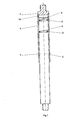
Figur 1 den Beutel mit Mischvorrichtung in Übersicht und -
Figur 2 die Verbindung von zwei Schaftelementen im Detail. - Gemäß
Figur 1 befindet sich im Beutel 1 ein Innenraum 2, der einen Rührstab bestehend aus zwei Rührelementen 3 und einem Mischerschaft aufnimmt. Der Mischerschaft besteht aus einem ersten Schaftelement 4 und einem zweiten Schaftelement 5. Dabei weist das erste Schaftelement einen Hohlkörper 6 auf, indem ein Füllkörper 7 des zweiten Schaftelements verschiebbar gelagert ist. - Gemäß
Figur 2 sind in das erste Schaftelement 4 zwei Nuten 8 eingearbeitet, in denen jeweils ein Ring 9 eingelassen ist. Im Hohlkörper 6 des ersten Schaftelements 4 befindet sich ein Kanal 10, der den Hohlraum des Hohlkörpers mit dem Innenraum 2 des Beutels verbindet. Die Verbindung ist vorzugsweise mit einem hydrophoben, für Gase durchlässigen und für Mikroorganismen und Zellen undurchlässigen Filter, welcher über die Öffnung gesiegelt ist, abgedeckt (nicht dargestellt). - Zwei O-Ringe mit einem Radius von 1 cm sollen ein Drehmoment von maximal 5 Nm übertragen. Die dafür notwendige Reibungskraft FR zwischen den O-Ringen, dem Hohlkörper und dem Füllkörper ergibt sich aus dem maximalen Drehmoment Mm, und dem Umfang der O-Ringe U. U = 2rπ = 0,0628 m Fr = Mm / U = 5 Nm / 0,0628 = 81 N Dementsprechend ist eine Kraft von ca. 80 N ausreichend, um die Reibungskraft der O-Ringe zu überwinden und eine Längenverstellung des Mischerschaftes durchzuführen.
- Eine Kraft, die manuell oder durch die Hilfe einfacher mechanischer Vorrichtungen leicht aufgebracht werden kann.
Claims (13)
- Flexibler Beutel (1) mit einer Mischvorrichtung, welche einen längenverstellbaren Mischerschaft, der in mindestens zwei oder mehrere Schaftelemente (4, 5) unterteilt ist, aufweist, dadurch gekennzeichnet, dass ein erstes von zwei benachbarten Schaftelementen (4) einen Hohlkörper (6) aufweist, in dem ein Füllkörper (7) eines zweiten Schaftelements (5) verschiebbar aufgenommen ist und sich in dem Spalt zwischen dem Hohlkörper (6) des ersten Schaftelements (4) und dem Füllkörper (7) des zweiten Schaftelements (5) mindestens ein elastisches Element (9) befindet und der Hohlraum im Innenraum des Mischerschaftes mit dem Innenraum (2) des Beutels (1) zum Druckausgleich durch einen Kanal (10) verbunden ist.
- Flexibler Beutel nach Anspruch 1, dadurch gekennzeichnet, dass zumindest die beiden äußeren Schaftelemente an der der Beutelwand zugewandten Seite geschlossen sind.
- Flexibler Beutel nach Anspruch 1, dadurch gekennzeichnet, dass der Hohlkörper (6) und der Füllkörper (7) der mindestens zwei Schaftelemente (4, 5) eine umlaufende, formschlüssige, ineinander greifende Kontur aufweisen.
- Flexibler Beutel nach Anspruch 3, dadurch gekennzeichnet, dass der Hohlkörper (6) und der Füllkörper (7) der mindestens zwei Schaftelemente (4, 5) drehrund ausgebildet sind.
- Flexibler Beutel nach Anspruch 3, dadurch gekennzeichnet, dass der Hohlkörper (6) und der Füllkörper (7) der mindestens zwei Schaftelemente (4, 5) vieleckig oder oval ausgebildet sind.
- Flexibler Beutel nach Anspruch 1, dadurch gekennzeichnet, dass das mindestens eine elastische Element (9) teilweise in eine Nut (8) auf dem Füllkörper (7) des zweiten Schaftelements oder in eine Nut in dem Hohlkörper (6) des ersten Schaftelements (4) eingelassen ist.
- Flexibler Beutel nach Anspruch 1, dadurch gekennzeichnet, dass das mindestens eine elastische Element (9) durch 2-K-Technologie an den Füllkörper (7) des zweiten Schaftelements (5) oder an den Hohlkörper (6) des ersten Schaftelements (4) angeformt ist.
- Flexibler Beutel nach Anspruch 1, dadurch gekennzeichnet, dass das mindestens eine elastische Element (9) aus zwei beabstandeten Ringen besteht.
- Flexibler Beutel nach einem der Ansprüche 1, 6, 7 oder 8, dadurch gekennzeichnet, dass durch das mindestens eine elastische Element (9) bei der Rotation des Mischerschaftes ein Drehmoment zwischen dem Hohlkörper (6) des ersten Schaftelements (4) und dem Füllkörper (7) des zweiten Schaftelements übertragbar ist.
- Flexibler Beutel nach Anspruch 1, dadurch gekennzeichnet, dass durch das mindestens eine elastische Element (9) der Hohlraum im Inneren des Mischerschaftes gegen Flüssigkeiten aus dem Innenraum des Beutels (2) abgedichtet ist.
- Flexibler Beutel nach Anspruch 1, dadurch gekennzeichnet, dass der Kanal (10) den Hohlraum im Inneren des Mischerschaftes und den mit Gas gefüllten Kopfraum des Beutels (1) zum Druckausgleich verbindet.
- Flexibler Beutel nach Anspruch 1 oder 11, dadurch gekennzeichnet, dass der Kanal (10) gegen Flüssigkeiten durch eine für Gase durchlässige und für Mikroorganismen und Zellen undurchlässige hydrophobe Membran abgedichtet ist.
- Flexibler Beutel nach einen der Ansprüche 6 bis 8, dadurch gekennzeichnet, dass der Hohlkörper (6) und/oder der Füllkörper (7) mindestens eine Nut aufweisen, in die eines der in einer Nut sitzenden oder durch 2-K-Technologie angeformten elastischen Elemente einrastbar ist.
Applications Claiming Priority (2)
| Application Number | Priority Date | Filing Date | Title |
|---|---|---|---|
| DE102008019213 | 2008-04-17 | ||
| EP09753580A EP2279039A2 (de) | 2008-04-17 | 2009-03-27 | Flexibler beutel mit einer mischvorrichtung |
Related Parent Applications (1)
| Application Number | Title | Priority Date | Filing Date |
|---|---|---|---|
| EP09753580.1 Division | 2009-03-27 |
Publications (2)
| Publication Number | Publication Date |
|---|---|
| EP2402073A1 true EP2402073A1 (de) | 2012-01-04 |
| EP2402073B1 EP2402073B1 (de) | 2013-01-23 |
Family
ID=40909855
Family Applications (2)
| Application Number | Title | Priority Date | Filing Date |
|---|---|---|---|
| EP09753580A Withdrawn EP2279039A2 (de) | 2008-04-17 | 2009-03-27 | Flexibler beutel mit einer mischvorrichtung |
| EP11007778A Active EP2402073B1 (de) | 2008-04-17 | 2009-03-27 | Flexibler Beutel mit einer Mischvorrichtung |
Family Applications Before (1)
| Application Number | Title | Priority Date | Filing Date |
|---|---|---|---|
| EP09753580A Withdrawn EP2279039A2 (de) | 2008-04-17 | 2009-03-27 | Flexibler beutel mit einer mischvorrichtung |
Country Status (4)
| Country | Link |
|---|---|
| US (1) | US8870443B2 (de) |
| EP (2) | EP2279039A2 (de) |
| DE (2) | DE202009005407U1 (de) |
| WO (1) | WO2009143925A2 (de) |
Cited By (1)
| Publication number | Priority date | Publication date | Assignee | Title |
|---|---|---|---|---|
| CN105251409A (zh) * | 2015-10-13 | 2016-01-20 | 芜湖美威包装品有限公司 | 一种纸浆的搅拌桨 |
Families Citing this family (33)
| Publication number | Priority date | Publication date | Assignee | Title |
|---|---|---|---|---|
| DE102006020461B3 (de) * | 2006-04-28 | 2007-10-04 | Sartorius Biotech Gmbh | Behälter mit flexiblen Wänden |
| FR2932697B1 (fr) * | 2008-06-20 | 2011-06-10 | Fillon Technologies | Dispositif d'agitation et son procede de reglage |
| FR2969506B1 (fr) | 2010-12-22 | 2013-02-15 | Sartorius Stedim Biotech Sa | Melange du contenu d'un conteneur flexible a usage biopharmaceutique. |
| US9643141B2 (en) | 2011-10-27 | 2017-05-09 | Trimr, Llc | Shakeable container with agitator |
| US9700857B1 (en) * | 2012-03-23 | 2017-07-11 | Life Technologies Corporation | Fluid mixing system with drive shaft steady support |
| EP3628396B1 (de) | 2012-04-06 | 2024-11-20 | Life Technologies Corporation | Flüssigkeitsmischsystem |
| IL221378A (en) * | 2012-08-09 | 2016-08-31 | Chen Ben-Ezra | Blocker to develop fluid port |
| DE102012019215B4 (de) * | 2012-10-01 | 2014-10-30 | Sartorius Stedim Biotech Gmbh | Rührereinbauhilfe und Verfahren zum Einbau eines Rührorgans in einen Bioreaktor |
| USD804247S1 (en) | 2012-10-26 | 2017-12-05 | Trimr, Llc | Agitator on straw or rod for a shakable container |
| CN104995029B (zh) * | 2013-01-18 | 2017-05-24 | 赛多利斯斯泰迪姆Fmt有限公司 | 用于一次性袋子的壁的包含核心层和外层的多层膜 |
| WO2014111549A1 (en) | 2013-01-18 | 2014-07-24 | Sartorius Stedim Fmt Sas | Multilayer film comprising a core layer and an outer layer for the wall of a single-use pouch |
| KR102179858B1 (ko) * | 2013-01-18 | 2020-11-18 | 사토리우스 스테딤 에프엠티 에스에이에스 | 1 회용 파우치의 벽에 사용되는, 접촉층, 코어층 및 외층을 포함하는 다층 필름 |
| US10427121B2 (en) * | 2013-02-01 | 2019-10-01 | Asociacion Centro De Investigacion Cooperativa En Biomateriales (Cic Biomagune) | Non intrusive agitation system |
| CN103341336B (zh) * | 2013-06-17 | 2015-09-16 | 济南卡博唐生物科技有限公司 | 搅拌釜的搅拌器 |
| CN103537219B (zh) * | 2013-06-18 | 2016-01-13 | 北京科技大学 | 一种风力搅拌充氧装置 |
| ITMO20130181A1 (it) * | 2013-06-24 | 2014-12-25 | Piovan Spa | Apparato di mescolazione per resine |
| DE102013106680B3 (de) * | 2013-06-26 | 2014-08-14 | Sartorius Stedim Biotech Gmbh | Behälter |
| CN103466171A (zh) * | 2013-09-13 | 2013-12-25 | 天津大田包装容器有限公司 | 一种带有搅拌装置的钢桶 |
| SG11201601940PA (en) | 2013-09-16 | 2016-04-28 | Genentech Inc | Bioreactors with multiple or adjustable -position agitator designs |
| WO2015095260A1 (en) | 2013-12-17 | 2015-06-25 | Bayer Cropscience Lp | Mixing systems, methods, and devices with extendible impellers |
| US9855537B2 (en) | 2014-03-22 | 2018-01-02 | Life Technologies Corporation | Impeller assemblies for fluid processing systems |
| CN104383827B (zh) * | 2014-09-29 | 2016-06-15 | 无锡康柏斯机械科技有限公司 | 一种直立双轴式正反联动粉碎、搅拌机 |
| FR3039776B1 (fr) | 2015-08-03 | 2017-08-25 | Sartorius Stedim Fmt Sas | Procede d'assemblage d'un recipient-melangeur comprenant un arbre telescopique. |
| JP7078535B2 (ja) | 2015-12-29 | 2022-05-31 | ライフ テクノロジーズ コーポレイション | 横方向に変位された可撓性駆動線を有する流体混合システム及び使用方法 |
| MX2018014681A (es) * | 2016-06-03 | 2019-06-06 | Lonza Ag | Biorreactor de un solo uso. |
| USD873305S1 (en) * | 2017-05-19 | 2020-01-21 | Superior Industries, Inc. | Attrition mill propeller |
| US11293003B2 (en) | 2018-01-17 | 2022-04-05 | Life Technologies Corporation | Configurable fluid mixing system housing and support hardware |
| USD929799S1 (en) * | 2018-05-04 | 2021-09-07 | Buss Ag | Screw shaft element |
| USD961990S1 (en) * | 2018-05-04 | 2022-08-30 | Buss Ag | Screw shaft element |
| USD885123S1 (en) * | 2018-07-24 | 2020-05-26 | David L. Vollmer, Jr. | Shaker bottle agitator |
| EP4100153A1 (de) | 2020-02-03 | 2022-12-14 | Life Technologies Corporation | Flüssigkeitsmischsysteme mit modularen laufrädern und zugehörige verfahren |
| US11998880B2 (en) | 2020-09-01 | 2024-06-04 | Global Life Sciences Solutions Usa Llc | Collapsible agitator assembly for a bioprocessing system |
| EP4221874A1 (de) * | 2020-10-02 | 2023-08-09 | Parker-Hannifin Corporation | Modulares mischlaufrad |
Citations (7)
| Publication number | Priority date | Publication date | Assignee | Title |
|---|---|---|---|---|
| US3246882A (en) * | 1963-02-22 | 1966-04-19 | Carves Simon Ltd | Apparatus for the aeration of liquids |
| GB1344316A (en) * | 1970-09-29 | 1974-01-23 | Siemens Ag | Mixing machines |
| JPH06285353A (ja) | 1993-04-06 | 1994-10-11 | Kawase Indasutoriii Kk | 混合機及びその攪拌装置 |
| US5765947A (en) * | 1996-03-22 | 1998-06-16 | Dubroy; Gary P. | Wind-up pot stirrer having spring tension and gear train mechanism |
| EP1541224A2 (de) * | 2003-07-14 | 2005-06-15 | José Ramon Rey Gamallo | Rührer für in Behältern enthaltenen chemischen Produkte |
| US20070102450A1 (en) * | 2005-09-19 | 2007-05-10 | Sven Stiers | Drain connector for substance processing receptacle |
| DE102006021984A1 (de) | 2006-05-10 | 2007-11-15 | Sartorius Biotech Gmbh | Bioreaktor |
Family Cites Families (9)
| Publication number | Priority date | Publication date | Assignee | Title |
|---|---|---|---|---|
| US3202281A (en) * | 1964-10-01 | 1965-08-24 | Weston David | Method for the flotation of finely divided minerals |
| US3357685A (en) * | 1966-06-28 | 1967-12-12 | Anait A Stephens | Battery-operated stirring unit for sauce pans and the like |
| AT372314B (de) * | 1981-07-03 | 1983-09-26 | Supervis Ets | Lenkspindel fuer lenkvorrichtungen bei kraftfahrzeugen |
| GB2195441A (en) | 1986-09-02 | 1988-04-07 | Ritchie Gordon S | In-line proximity switch |
| US5078506A (en) * | 1991-04-05 | 1992-01-07 | G. Heileman Brewing Company, Inc. | Bottom entry mixer shaft seal system for process vessels |
| US5906543A (en) * | 1997-03-18 | 1999-05-25 | The Torrington Company | Low or no-lash slider shaft for a steering column |
| ES2238009B2 (es) * | 2004-01-28 | 2007-07-16 | Melchor Daumal Castellon | Eje intermedio de baja carga de deslizamiento de la columna de direccion de vehiculos automoviles. |
| DE102007061664B4 (de) * | 2007-12-18 | 2009-11-19 | Sartorius Stedim Biotech Gmbh | Behälter mit flexibler Wandung |
| EP3628396B1 (de) * | 2012-04-06 | 2024-11-20 | Life Technologies Corporation | Flüssigkeitsmischsystem |
-
2009
- 2009-03-27 US US12/933,453 patent/US8870443B2/en active Active
- 2009-03-27 EP EP09753580A patent/EP2279039A2/de not_active Withdrawn
- 2009-03-27 EP EP11007778A patent/EP2402073B1/de active Active
- 2009-03-27 WO PCT/EP2009/002281 patent/WO2009143925A2/de not_active Ceased
- 2009-04-08 DE DE202009005407U patent/DE202009005407U1/de not_active Expired - Lifetime
- 2009-04-11 DE DE102009018209A patent/DE102009018209A1/de not_active Withdrawn
Patent Citations (7)
| Publication number | Priority date | Publication date | Assignee | Title |
|---|---|---|---|---|
| US3246882A (en) * | 1963-02-22 | 1966-04-19 | Carves Simon Ltd | Apparatus for the aeration of liquids |
| GB1344316A (en) * | 1970-09-29 | 1974-01-23 | Siemens Ag | Mixing machines |
| JPH06285353A (ja) | 1993-04-06 | 1994-10-11 | Kawase Indasutoriii Kk | 混合機及びその攪拌装置 |
| US5765947A (en) * | 1996-03-22 | 1998-06-16 | Dubroy; Gary P. | Wind-up pot stirrer having spring tension and gear train mechanism |
| EP1541224A2 (de) * | 2003-07-14 | 2005-06-15 | José Ramon Rey Gamallo | Rührer für in Behältern enthaltenen chemischen Produkte |
| US20070102450A1 (en) * | 2005-09-19 | 2007-05-10 | Sven Stiers | Drain connector for substance processing receptacle |
| DE102006021984A1 (de) | 2006-05-10 | 2007-11-15 | Sartorius Biotech Gmbh | Bioreaktor |
Cited By (1)
| Publication number | Priority date | Publication date | Assignee | Title |
|---|---|---|---|---|
| CN105251409A (zh) * | 2015-10-13 | 2016-01-20 | 芜湖美威包装品有限公司 | 一种纸浆的搅拌桨 |
Also Published As
| Publication number | Publication date |
|---|---|
| US20110026360A1 (en) | 2011-02-03 |
| EP2402073B1 (de) | 2013-01-23 |
| DE202009005407U1 (de) | 2009-09-17 |
| WO2009143925A2 (de) | 2009-12-03 |
| EP2279039A2 (de) | 2011-02-02 |
| US8870443B2 (en) | 2014-10-28 |
| WO2009143925A3 (de) | 2010-03-25 |
| DE102009018209A1 (de) | 2009-10-22 |
Similar Documents
| Publication | Publication Date | Title |
|---|---|---|
| EP2402073B1 (de) | Flexibler Beutel mit einer Mischvorrichtung | |
| DE102007061664B4 (de) | Behälter mit flexibler Wandung | |
| DE69706281T2 (de) | Deckel und Behälter zum Abgeben von Flüssigkeiten wie z.B. Leim | |
| DE112010003746B4 (de) | Komprimierbarer Rotor für eine Fluidpumpe | |
| EP2384822B2 (de) | Kartuschenverschluss und Kartusche mit einem solchen Verschluss | |
| EP2596873B1 (de) | Mehrkomponenten-Kartuschensystem mit verschiebbaren Verschlüssen in den Kartuschen | |
| EP3153121B1 (de) | Vorrichtung und verfahren zum öffnen von glasampullen sowie zementiervorrichtung | |
| EP2898055B1 (de) | Behälter, transportvorrichtung, verwendung und verfahren | |
| WO2012038038A1 (de) | Mehrkomponenten-mischsystem mit drehbarem behälter und behälter dafür | |
| DE102014109905A1 (de) | Vakuummischsystem und Verfahren zum Mischen von Polymethylmethacrylat-Knochenzement | |
| DE102012024710A1 (de) | Vorrichtung zum Mischen und Austragen einer pastösen Masse | |
| EP3471868A1 (de) | Vibromischer zum mischen von flüssigkeiten, flüssigkeiten mit gasen oder feststoffen in flexiblen einwegbehältern | |
| EP2379211A1 (de) | Mischvorrichtung mit anzeige für druckänderung | |
| EP2513285B1 (de) | Behälter einer biogasanlage sowie verfahren zur entnahme einer komponente aus dem behälter | |
| DE102015117270A1 (de) | Pasten-Applikationsvorrichtung zum Mischen einer Paste | |
| EP3227011B1 (de) | Mischvorrichtung mit strömungsbrecher | |
| DE102012018597B4 (de) | Austragsvorrichtung für fließfähige Massen und Verwendung der Austragsvorrichtung | |
| DE102015011881B4 (de) | Mischsystem und Verfahren zum Mischen eines Fluids und/oder eines Feststoffs | |
| WO2019029913A1 (de) | Mischvorrichtung und verfahren zum betreiben einer mischvorrichtung | |
| DE102016005240B4 (de) | Mischvorrichtung | |
| WO2020234189A1 (de) | VERSCHLUSS ZUM FLUIDDICHTEN VERSCHLIEßEN EINES MIT EINEM STOFF GEFÜLLTEN GEFÄßES, BEHÄLTER MIT EINEM GEFÄß UND EINEM VERSCHLUSS SOWIE VERFAHREN ZUM BEFÜLLEN EINES BEHÄLTERS MIT EINEM STOFF | |
| DE2920747C3 (de) | Vorrichtung zum abdichtenden Verbinden eines Transportbehälters mit der gestellfesten, nach oben offenen Aufnahme einer Einrichtung zur dosierten Abgabe von Flüssigkeiten in Geräten zum Ausgeben von Getränken | |
| DE2402528A1 (de) | Pumpe zum zuliefern intravenoes einzufuehrender substanzen | |
| DE102009057315A1 (de) | Ventilsystem für einen Fluidbehälter | |
| EP1775238A1 (de) | Aufbewahrungs- und Entleerungsvorrichtung |
Legal Events
| Date | Code | Title | Description |
|---|---|---|---|
| AC | Divisional application: reference to earlier application |
Ref document number: 2279039 Country of ref document: EP Kind code of ref document: P |
|
| AK | Designated contracting states |
Kind code of ref document: A1 Designated state(s): AT BE BG CH CY CZ DE DK EE ES FI FR GB GR HR HU IE IS IT LI LT LU LV MC MK MT NL NO PL PT RO SE SI SK TR |
|
| PUAI | Public reference made under article 153(3) epc to a published international application that has entered the european phase |
Free format text: ORIGINAL CODE: 0009012 |
|
| 17P | Request for examination filed |
Effective date: 20120704 |
|
| GRAP | Despatch of communication of intention to grant a patent |
Free format text: ORIGINAL CODE: EPIDOSNIGR1 |
|
| GRAS | Grant fee paid |
Free format text: ORIGINAL CODE: EPIDOSNIGR3 |
|
| GRAA | (expected) grant |
Free format text: ORIGINAL CODE: 0009210 |
|
| AC | Divisional application: reference to earlier application |
Ref document number: 2279039 Country of ref document: EP Kind code of ref document: P |
|
| AK | Designated contracting states |
Kind code of ref document: B1 Designated state(s): AT BE BG CH CY CZ DE DK EE ES FI FR GB GR HR HU IE IS IT LI LT LU LV MC MK MT NL NO PL PT RO SE SI SK TR |
|
| REG | Reference to a national code |
Ref country code: GB Ref legal event code: FG4D Free format text: NOT ENGLISH |
|
| REG | Reference to a national code |
Ref country code: CH Ref legal event code: EP |
|
| REG | Reference to a national code |
Ref country code: AT Ref legal event code: REF Ref document number: 594647 Country of ref document: AT Kind code of ref document: T Effective date: 20130215 Ref country code: CH Ref legal event code: EP |
|
| REG | Reference to a national code |
Ref country code: IE Ref legal event code: FG4D Free format text: LANGUAGE OF EP DOCUMENT: GERMAN |
|
| REG | Reference to a national code |
Ref country code: DE Ref legal event code: R096 Ref document number: 502009006143 Country of ref document: DE Effective date: 20130321 |
|
| REG | Reference to a national code |
Ref country code: LT Ref legal event code: MG4D |
|
| REG | Reference to a national code |
Ref country code: NL Ref legal event code: VDEP Effective date: 20130123 |
|
| PG25 | Lapsed in a contracting state [announced via postgrant information from national office to epo] |
Ref country code: LT Free format text: LAPSE BECAUSE OF FAILURE TO SUBMIT A TRANSLATION OF THE DESCRIPTION OR TO PAY THE FEE WITHIN THE PRESCRIBED TIME-LIMIT Effective date: 20130123 Ref country code: SE Free format text: LAPSE BECAUSE OF FAILURE TO SUBMIT A TRANSLATION OF THE DESCRIPTION OR TO PAY THE FEE WITHIN THE PRESCRIBED TIME-LIMIT Effective date: 20130123 Ref country code: BG Free format text: LAPSE BECAUSE OF FAILURE TO SUBMIT A TRANSLATION OF THE DESCRIPTION OR TO PAY THE FEE WITHIN THE PRESCRIBED TIME-LIMIT Effective date: 20130423 Ref country code: NO Free format text: LAPSE BECAUSE OF FAILURE TO SUBMIT A TRANSLATION OF THE DESCRIPTION OR TO PAY THE FEE WITHIN THE PRESCRIBED TIME-LIMIT Effective date: 20130423 Ref country code: ES Free format text: LAPSE BECAUSE OF FAILURE TO SUBMIT A TRANSLATION OF THE DESCRIPTION OR TO PAY THE FEE WITHIN THE PRESCRIBED TIME-LIMIT Effective date: 20130504 Ref country code: IS Free format text: LAPSE BECAUSE OF FAILURE TO SUBMIT A TRANSLATION OF THE DESCRIPTION OR TO PAY THE FEE WITHIN THE PRESCRIBED TIME-LIMIT Effective date: 20130523 |
|
| PG25 | Lapsed in a contracting state [announced via postgrant information from national office to epo] |
Ref country code: GR Free format text: LAPSE BECAUSE OF FAILURE TO SUBMIT A TRANSLATION OF THE DESCRIPTION OR TO PAY THE FEE WITHIN THE PRESCRIBED TIME-LIMIT Effective date: 20130424 Ref country code: SI Free format text: LAPSE BECAUSE OF FAILURE TO SUBMIT A TRANSLATION OF THE DESCRIPTION OR TO PAY THE FEE WITHIN THE PRESCRIBED TIME-LIMIT Effective date: 20130123 Ref country code: PL Free format text: LAPSE BECAUSE OF FAILURE TO SUBMIT A TRANSLATION OF THE DESCRIPTION OR TO PAY THE FEE WITHIN THE PRESCRIBED TIME-LIMIT Effective date: 20130123 Ref country code: PT Free format text: LAPSE BECAUSE OF FAILURE TO SUBMIT A TRANSLATION OF THE DESCRIPTION OR TO PAY THE FEE WITHIN THE PRESCRIBED TIME-LIMIT Effective date: 20130523 Ref country code: NL Free format text: LAPSE BECAUSE OF FAILURE TO SUBMIT A TRANSLATION OF THE DESCRIPTION OR TO PAY THE FEE WITHIN THE PRESCRIBED TIME-LIMIT Effective date: 20130123 Ref country code: FI Free format text: LAPSE BECAUSE OF FAILURE TO SUBMIT A TRANSLATION OF THE DESCRIPTION OR TO PAY THE FEE WITHIN THE PRESCRIBED TIME-LIMIT Effective date: 20130123 Ref country code: LV Free format text: LAPSE BECAUSE OF FAILURE TO SUBMIT A TRANSLATION OF THE DESCRIPTION OR TO PAY THE FEE WITHIN THE PRESCRIBED TIME-LIMIT Effective date: 20130123 |
|
| BERE | Be: lapsed |
Owner name: SARTORIUS STEDIM BIOTECH G.M.B.H. Effective date: 20130331 |
|
| PG25 | Lapsed in a contracting state [announced via postgrant information from national office to epo] |
Ref country code: HR Free format text: LAPSE BECAUSE OF FAILURE TO SUBMIT A TRANSLATION OF THE DESCRIPTION OR TO PAY THE FEE WITHIN THE PRESCRIBED TIME-LIMIT Effective date: 20130123 |
|
| PG25 | Lapsed in a contracting state [announced via postgrant information from national office to epo] |
Ref country code: MC Free format text: LAPSE BECAUSE OF NON-PAYMENT OF DUE FEES Effective date: 20130331 Ref country code: EE Free format text: LAPSE BECAUSE OF FAILURE TO SUBMIT A TRANSLATION OF THE DESCRIPTION OR TO PAY THE FEE WITHIN THE PRESCRIBED TIME-LIMIT Effective date: 20130123 Ref country code: DK Free format text: LAPSE BECAUSE OF FAILURE TO SUBMIT A TRANSLATION OF THE DESCRIPTION OR TO PAY THE FEE WITHIN THE PRESCRIBED TIME-LIMIT Effective date: 20130123 Ref country code: SK Free format text: LAPSE BECAUSE OF FAILURE TO SUBMIT A TRANSLATION OF THE DESCRIPTION OR TO PAY THE FEE WITHIN THE PRESCRIBED TIME-LIMIT Effective date: 20130123 Ref country code: RO Free format text: LAPSE BECAUSE OF FAILURE TO SUBMIT A TRANSLATION OF THE DESCRIPTION OR TO PAY THE FEE WITHIN THE PRESCRIBED TIME-LIMIT Effective date: 20130123 Ref country code: CZ Free format text: LAPSE BECAUSE OF FAILURE TO SUBMIT A TRANSLATION OF THE DESCRIPTION OR TO PAY THE FEE WITHIN THE PRESCRIBED TIME-LIMIT Effective date: 20130123 |
|
| REG | Reference to a national code |
Ref country code: CH Ref legal event code: PL |
|
| PG25 | Lapsed in a contracting state [announced via postgrant information from national office to epo] |
Ref country code: CY Free format text: LAPSE BECAUSE OF FAILURE TO SUBMIT A TRANSLATION OF THE DESCRIPTION OR TO PAY THE FEE WITHIN THE PRESCRIBED TIME-LIMIT Effective date: 20130123 |
|
| PLBE | No opposition filed within time limit |
Free format text: ORIGINAL CODE: 0009261 |
|
| STAA | Information on the status of an ep patent application or granted ep patent |
Free format text: STATUS: NO OPPOSITION FILED WITHIN TIME LIMIT |
|
| PG25 | Lapsed in a contracting state [announced via postgrant information from national office to epo] |
Ref country code: IT Free format text: LAPSE BECAUSE OF FAILURE TO SUBMIT A TRANSLATION OF THE DESCRIPTION OR TO PAY THE FEE WITHIN THE PRESCRIBED TIME-LIMIT Effective date: 20130123 |
|
| 26N | No opposition filed |
Effective date: 20131024 |
|
| REG | Reference to a national code |
Ref country code: IE Ref legal event code: MM4A |
|
| PG25 | Lapsed in a contracting state [announced via postgrant information from national office to epo] |
Ref country code: LI Free format text: LAPSE BECAUSE OF NON-PAYMENT OF DUE FEES Effective date: 20130331 Ref country code: BE Free format text: LAPSE BECAUSE OF NON-PAYMENT OF DUE FEES Effective date: 20130331 Ref country code: IE Free format text: LAPSE BECAUSE OF NON-PAYMENT OF DUE FEES Effective date: 20130327 Ref country code: CH Free format text: LAPSE BECAUSE OF NON-PAYMENT OF DUE FEES Effective date: 20130331 |
|
| REG | Reference to a national code |
Ref country code: DE Ref legal event code: R097 Ref document number: 502009006143 Country of ref document: DE Effective date: 20131024 |
|
| PG25 | Lapsed in a contracting state [announced via postgrant information from national office to epo] |
Ref country code: MT Free format text: LAPSE BECAUSE OF FAILURE TO SUBMIT A TRANSLATION OF THE DESCRIPTION OR TO PAY THE FEE WITHIN THE PRESCRIBED TIME-LIMIT Effective date: 20130123 |
|
| REG | Reference to a national code |
Ref country code: AT Ref legal event code: MM01 Ref document number: 594647 Country of ref document: AT Kind code of ref document: T Effective date: 20140327 |
|
| PG25 | Lapsed in a contracting state [announced via postgrant information from national office to epo] |
Ref country code: TR Free format text: LAPSE BECAUSE OF FAILURE TO SUBMIT A TRANSLATION OF THE DESCRIPTION OR TO PAY THE FEE WITHIN THE PRESCRIBED TIME-LIMIT Effective date: 20130123 |
|
| PG25 | Lapsed in a contracting state [announced via postgrant information from national office to epo] |
Ref country code: LU Free format text: LAPSE BECAUSE OF NON-PAYMENT OF DUE FEES Effective date: 20130327 Ref country code: HU Free format text: LAPSE BECAUSE OF FAILURE TO SUBMIT A TRANSLATION OF THE DESCRIPTION OR TO PAY THE FEE WITHIN THE PRESCRIBED TIME-LIMIT; INVALID AB INITIO Effective date: 20090327 Ref country code: MK Free format text: LAPSE BECAUSE OF FAILURE TO SUBMIT A TRANSLATION OF THE DESCRIPTION OR TO PAY THE FEE WITHIN THE PRESCRIBED TIME-LIMIT Effective date: 20130123 |
|
| PG25 | Lapsed in a contracting state [announced via postgrant information from national office to epo] |
Ref country code: AT Free format text: LAPSE BECAUSE OF NON-PAYMENT OF DUE FEES Effective date: 20140327 |
|
| REG | Reference to a national code |
Ref country code: FR Ref legal event code: PLFP Year of fee payment: 8 |
|
| REG | Reference to a national code |
Ref country code: FR Ref legal event code: PLFP Year of fee payment: 9 |
|
| REG | Reference to a national code |
Ref country code: FR Ref legal event code: PLFP Year of fee payment: 10 |
|
| REG | Reference to a national code |
Ref country code: DE Ref legal event code: R079 Ref document number: 502009006143 Country of ref document: DE Free format text: PREVIOUS MAIN CLASS: B01F0015000000 Ipc: B01F0035000000 |
|
| P01 | Opt-out of the competence of the unified patent court (upc) registered |
Effective date: 20230526 |
|
| PGFP | Annual fee paid to national office [announced via postgrant information from national office to epo] |
Ref country code: GB Payment date: 20260324 Year of fee payment: 18 |
|
| PGFP | Annual fee paid to national office [announced via postgrant information from national office to epo] |
Ref country code: DE Payment date: 20260320 Year of fee payment: 18 |
|
| PGFP | Annual fee paid to national office [announced via postgrant information from national office to epo] |
Ref country code: FR Payment date: 20260325 Year of fee payment: 18 |