EP2401092B1 - Lubrication mechanism for can processing machine - Google Patents
Lubrication mechanism for can processing machine Download PDFInfo
- Publication number
- EP2401092B1 EP2401092B1 EP10705733.3A EP10705733A EP2401092B1 EP 2401092 B1 EP2401092 B1 EP 2401092B1 EP 10705733 A EP10705733 A EP 10705733A EP 2401092 B1 EP2401092 B1 EP 2401092B1
- Authority
- EP
- European Patent Office
- Prior art keywords
- lubricating
- lubricant
- pockets
- track
- guide member
- Prior art date
- Legal status (The legal status is an assumption and is not a legal conclusion. Google has not performed a legal analysis and makes no representation as to the accuracy of the status listed.)
- Active
Links
Images





Classifications
-
- B—PERFORMING OPERATIONS; TRANSPORTING
- B21—MECHANICAL METAL-WORKING WITHOUT ESSENTIALLY REMOVING MATERIAL; PUNCHING METAL
- B21D—WORKING OR PROCESSING OF SHEET METAL OR METAL TUBES, RODS OR PROFILES WITHOUT ESSENTIALLY REMOVING MATERIAL; PUNCHING METAL
- B21D21/00—Combined processes according to methods covered by groups B21D1/00 - B21D19/00
-
- B—PERFORMING OPERATIONS; TRANSPORTING
- B21—MECHANICAL METAL-WORKING WITHOUT ESSENTIALLY REMOVING MATERIAL; PUNCHING METAL
- B21D—WORKING OR PROCESSING OF SHEET METAL OR METAL TUBES, RODS OR PROFILES WITHOUT ESSENTIALLY REMOVING MATERIAL; PUNCHING METAL
- B21D37/00—Tools as parts of machines covered by this subclass
- B21D37/18—Lubricating, e.g. lubricating tool and workpiece simultaneously
-
- B—PERFORMING OPERATIONS; TRANSPORTING
- B21—MECHANICAL METAL-WORKING WITHOUT ESSENTIALLY REMOVING MATERIAL; PUNCHING METAL
- B21D—WORKING OR PROCESSING OF SHEET METAL OR METAL TUBES, RODS OR PROFILES WITHOUT ESSENTIALLY REMOVING MATERIAL; PUNCHING METAL
- B21D51/00—Making hollow objects
- B21D51/16—Making hollow objects characterised by the use of the objects
- B21D51/26—Making hollow objects characterised by the use of the objects cans or tins; Closing same in a permanent manner
-
- B—PERFORMING OPERATIONS; TRANSPORTING
- B21—MECHANICAL METAL-WORKING WITHOUT ESSENTIALLY REMOVING MATERIAL; PUNCHING METAL
- B21D—WORKING OR PROCESSING OF SHEET METAL OR METAL TUBES, RODS OR PROFILES WITHOUT ESSENTIALLY REMOVING MATERIAL; PUNCHING METAL
- B21D51/00—Making hollow objects
- B21D51/16—Making hollow objects characterised by the use of the objects
- B21D51/26—Making hollow objects characterised by the use of the objects cans or tins; Closing same in a permanent manner
- B21D51/2615—Edge treatment of cans or tins
-
- B—PERFORMING OPERATIONS; TRANSPORTING
- B21—MECHANICAL METAL-WORKING WITHOUT ESSENTIALLY REMOVING MATERIAL; PUNCHING METAL
- B21D—WORKING OR PROCESSING OF SHEET METAL OR METAL TUBES, RODS OR PROFILES WITHOUT ESSENTIALLY REMOVING MATERIAL; PUNCHING METAL
- B21D51/00—Making hollow objects
- B21D51/16—Making hollow objects characterised by the use of the objects
- B21D51/26—Making hollow objects characterised by the use of the objects cans or tins; Closing same in a permanent manner
- B21D51/2615—Edge treatment of cans or tins
- B21D51/2638—Necking
-
- B—PERFORMING OPERATIONS; TRANSPORTING
- B21—MECHANICAL METAL-WORKING WITHOUT ESSENTIALLY REMOVING MATERIAL; PUNCHING METAL
- B21D—WORKING OR PROCESSING OF SHEET METAL OR METAL TUBES, RODS OR PROFILES WITHOUT ESSENTIALLY REMOVING MATERIAL; PUNCHING METAL
- B21D51/00—Making hollow objects
- B21D51/16—Making hollow objects characterised by the use of the objects
- B21D51/26—Making hollow objects characterised by the use of the objects cans or tins; Closing same in a permanent manner
- B21D51/2692—Manipulating, e.g. feeding and positioning devices; Control systems
-
- B—PERFORMING OPERATIONS; TRANSPORTING
- B23—MACHINE TOOLS; METAL-WORKING NOT OTHERWISE PROVIDED FOR
- B23Q—DETAILS, COMPONENTS, OR ACCESSORIES FOR MACHINE TOOLS, e.g. ARRANGEMENTS FOR COPYING OR CONTROLLING; MACHINE TOOLS IN GENERAL CHARACTERISED BY THE CONSTRUCTION OF PARTICULAR DETAILS OR COMPONENTS; COMBINATIONS OR ASSOCIATIONS OF METAL-WORKING MACHINES, NOT DIRECTED TO A PARTICULAR RESULT
- B23Q3/00—Devices holding, supporting, or positioning work or tools, of a kind normally removable from the machine
- B23Q3/02—Devices holding, supporting, or positioning work or tools, of a kind normally removable from the machine for mounting on a work-table, tool-slide, or analogous part
- B23Q3/06—Work-clamping means
- B23Q3/061—Work-clamping means adapted for holding a plurality of workpieces
-
- B—PERFORMING OPERATIONS; TRANSPORTING
- B23—MACHINE TOOLS; METAL-WORKING NOT OTHERWISE PROVIDED FOR
- B23Q—DETAILS, COMPONENTS, OR ACCESSORIES FOR MACHINE TOOLS, e.g. ARRANGEMENTS FOR COPYING OR CONTROLLING; MACHINE TOOLS IN GENERAL CHARACTERISED BY THE CONSTRUCTION OF PARTICULAR DETAILS OR COMPONENTS; COMBINATIONS OR ASSOCIATIONS OF METAL-WORKING MACHINES, NOT DIRECTED TO A PARTICULAR RESULT
- B23Q39/00—Metal-working machines incorporating a plurality of sub-assemblies, each capable of performing a metal-working operation
- B23Q39/02—Metal-working machines incorporating a plurality of sub-assemblies, each capable of performing a metal-working operation the sub-assemblies being capable of being brought to act at a single operating station
- B23Q39/028—Metal-working machines incorporating a plurality of sub-assemblies, each capable of performing a metal-working operation the sub-assemblies being capable of being brought to act at a single operating station with a plurality of workholder per toolhead in operating position
-
- B—PERFORMING OPERATIONS; TRANSPORTING
- B23—MACHINE TOOLS; METAL-WORKING NOT OTHERWISE PROVIDED FOR
- B23Q—DETAILS, COMPONENTS, OR ACCESSORIES FOR MACHINE TOOLS, e.g. ARRANGEMENTS FOR COPYING OR CONTROLLING; MACHINE TOOLS IN GENERAL CHARACTERISED BY THE CONSTRUCTION OF PARTICULAR DETAILS OR COMPONENTS; COMBINATIONS OR ASSOCIATIONS OF METAL-WORKING MACHINES, NOT DIRECTED TO A PARTICULAR RESULT
- B23Q39/00—Metal-working machines incorporating a plurality of sub-assemblies, each capable of performing a metal-working operation
- B23Q39/04—Metal-working machines incorporating a plurality of sub-assemblies, each capable of performing a metal-working operation the sub-assemblies being arranged to operate simultaneously at different stations, e.g. with an annular work-table moved in steps
- B23Q39/042—Metal-working machines incorporating a plurality of sub-assemblies, each capable of performing a metal-working operation the sub-assemblies being arranged to operate simultaneously at different stations, e.g. with an annular work-table moved in steps with circular arrangement of the sub-assemblies
- B23Q39/044—Metal-working machines incorporating a plurality of sub-assemblies, each capable of performing a metal-working operation the sub-assemblies being arranged to operate simultaneously at different stations, e.g. with an annular work-table moved in steps with circular arrangement of the sub-assemblies having at least one tool station cooperating with each work holder, e.g. multi-spindle lathes
-
- B—PERFORMING OPERATIONS; TRANSPORTING
- B23—MACHINE TOOLS; METAL-WORKING NOT OTHERWISE PROVIDED FOR
- B23Q—DETAILS, COMPONENTS, OR ACCESSORIES FOR MACHINE TOOLS, e.g. ARRANGEMENTS FOR COPYING OR CONTROLLING; MACHINE TOOLS IN GENERAL CHARACTERISED BY THE CONSTRUCTION OF PARTICULAR DETAILS OR COMPONENTS; COMBINATIONS OR ASSOCIATIONS OF METAL-WORKING MACHINES, NOT DIRECTED TO A PARTICULAR RESULT
- B23Q7/00—Arrangements for handling work specially combined with or arranged in, or specially adapted for use in connection with, machine tools, e.g. for conveying, loading, positioning, discharging, sorting
- B23Q7/02—Arrangements for handling work specially combined with or arranged in, or specially adapted for use in connection with, machine tools, e.g. for conveying, loading, positioning, discharging, sorting by means of drums or rotating tables or discs
-
- F—MECHANICAL ENGINEERING; LIGHTING; HEATING; WEAPONS; BLASTING
- F16—ENGINEERING ELEMENTS AND UNITS; GENERAL MEASURES FOR PRODUCING AND MAINTAINING EFFECTIVE FUNCTIONING OF MACHINES OR INSTALLATIONS; THERMAL INSULATION IN GENERAL
- F16K—VALVES; TAPS; COCKS; ACTUATING-FLOATS; DEVICES FOR VENTING OR AERATING
- F16K3/00—Gate valves or sliding valves, i.e. cut-off apparatus with closing members having a sliding movement along the seat for opening and closing
- F16K3/02—Gate valves or sliding valves, i.e. cut-off apparatus with closing members having a sliding movement along the seat for opening and closing with flat sealing faces; Packings therefor
- F16K3/0218—Gate valves or sliding valves, i.e. cut-off apparatus with closing members having a sliding movement along the seat for opening and closing with flat sealing faces; Packings therefor with only one sealing face
-
- F—MECHANICAL ENGINEERING; LIGHTING; HEATING; WEAPONS; BLASTING
- F16—ENGINEERING ELEMENTS AND UNITS; GENERAL MEASURES FOR PRODUCING AND MAINTAINING EFFECTIVE FUNCTIONING OF MACHINES OR INSTALLATIONS; THERMAL INSULATION IN GENERAL
- F16K—VALVES; TAPS; COCKS; ACTUATING-FLOATS; DEVICES FOR VENTING OR AERATING
- F16K3/00—Gate valves or sliding valves, i.e. cut-off apparatus with closing members having a sliding movement along the seat for opening and closing
- F16K3/02—Gate valves or sliding valves, i.e. cut-off apparatus with closing members having a sliding movement along the seat for opening and closing with flat sealing faces; Packings therefor
- F16K3/0227—Packings
- F16K3/0236—Packings the packing being of a non-resilient material, e.g. ceramic, metal
-
- Y—GENERAL TAGGING OF NEW TECHNOLOGICAL DEVELOPMENTS; GENERAL TAGGING OF CROSS-SECTIONAL TECHNOLOGIES SPANNING OVER SEVERAL SECTIONS OF THE IPC; TECHNICAL SUBJECTS COVERED BY FORMER USPC CROSS-REFERENCE ART COLLECTIONS [XRACs] AND DIGESTS
- Y10—TECHNICAL SUBJECTS COVERED BY FORMER USPC
- Y10T—TECHNICAL SUBJECTS COVERED BY FORMER US CLASSIFICATION
- Y10T279/00—Chucks or sockets
- Y10T279/10—Expanding
- Y10T279/1037—Axially moving actuator
- Y10T279/1041—Wedge
-
- Y—GENERAL TAGGING OF NEW TECHNOLOGICAL DEVELOPMENTS; GENERAL TAGGING OF CROSS-SECTIONAL TECHNOLOGIES SPANNING OVER SEVERAL SECTIONS OF THE IPC; TECHNICAL SUBJECTS COVERED BY FORMER USPC CROSS-REFERENCE ART COLLECTIONS [XRACs] AND DIGESTS
- Y10—TECHNICAL SUBJECTS COVERED BY FORMER USPC
- Y10T—TECHNICAL SUBJECTS COVERED BY FORMER US CLASSIFICATION
- Y10T279/00—Chucks or sockets
- Y10T279/32—Means to prevent jaw loosening
-
- Y—GENERAL TAGGING OF NEW TECHNOLOGICAL DEVELOPMENTS; GENERAL TAGGING OF CROSS-SECTIONAL TECHNOLOGIES SPANNING OVER SEVERAL SECTIONS OF THE IPC; TECHNICAL SUBJECTS COVERED BY FORMER USPC CROSS-REFERENCE ART COLLECTIONS [XRACs] AND DIGESTS
- Y10—TECHNICAL SUBJECTS COVERED BY FORMER USPC
- Y10T—TECHNICAL SUBJECTS COVERED BY FORMER US CLASSIFICATION
- Y10T29/00—Metal working
- Y10T29/51—Plural diverse manufacturing apparatus including means for metal shaping or assembling
- Y10T29/5152—Plural diverse manufacturing apparatus including means for metal shaping or assembling with turret mechanism
-
- Y—GENERAL TAGGING OF NEW TECHNOLOGICAL DEVELOPMENTS; GENERAL TAGGING OF CROSS-SECTIONAL TECHNOLOGIES SPANNING OVER SEVERAL SECTIONS OF THE IPC; TECHNICAL SUBJECTS COVERED BY FORMER USPC CROSS-REFERENCE ART COLLECTIONS [XRACs] AND DIGESTS
- Y10—TECHNICAL SUBJECTS COVERED BY FORMER USPC
- Y10T—TECHNICAL SUBJECTS COVERED BY FORMER US CLASSIFICATION
- Y10T29/00—Metal working
- Y10T29/51—Plural diverse manufacturing apparatus including means for metal shaping or assembling
- Y10T29/5152—Plural diverse manufacturing apparatus including means for metal shaping or assembling with turret mechanism
- Y10T29/5165—Plural diverse manufacturing apparatus including means for metal shaping or assembling with turret mechanism including rotating and/or locking means
-
- Y—GENERAL TAGGING OF NEW TECHNOLOGICAL DEVELOPMENTS; GENERAL TAGGING OF CROSS-SECTIONAL TECHNOLOGIES SPANNING OVER SEVERAL SECTIONS OF THE IPC; TECHNICAL SUBJECTS COVERED BY FORMER USPC CROSS-REFERENCE ART COLLECTIONS [XRACs] AND DIGESTS
- Y10—TECHNICAL SUBJECTS COVERED BY FORMER USPC
- Y10T—TECHNICAL SUBJECTS COVERED BY FORMER US CLASSIFICATION
- Y10T29/00—Metal working
- Y10T29/51—Plural diverse manufacturing apparatus including means for metal shaping or assembling
- Y10T29/519—Turret
-
- Y—GENERAL TAGGING OF NEW TECHNOLOGICAL DEVELOPMENTS; GENERAL TAGGING OF CROSS-SECTIONAL TECHNOLOGIES SPANNING OVER SEVERAL SECTIONS OF THE IPC; TECHNICAL SUBJECTS COVERED BY FORMER USPC CROSS-REFERENCE ART COLLECTIONS [XRACs] AND DIGESTS
- Y10—TECHNICAL SUBJECTS COVERED BY FORMER USPC
- Y10T—TECHNICAL SUBJECTS COVERED BY FORMER US CLASSIFICATION
- Y10T403/00—Joints and connections
- Y10T403/70—Interfitted members
- Y10T403/7018—Interfitted members including separably interposed key
- Y10T403/7021—Axially extending
- Y10T403/7024—Longitudinally stepped or tapered
-
- Y—GENERAL TAGGING OF NEW TECHNOLOGICAL DEVELOPMENTS; GENERAL TAGGING OF CROSS-SECTIONAL TECHNOLOGIES SPANNING OVER SEVERAL SECTIONS OF THE IPC; TECHNICAL SUBJECTS COVERED BY FORMER USPC CROSS-REFERENCE ART COLLECTIONS [XRACs] AND DIGESTS
- Y10—TECHNICAL SUBJECTS COVERED BY FORMER USPC
- Y10T—TECHNICAL SUBJECTS COVERED BY FORMER US CLASSIFICATION
- Y10T403/00—Joints and connections
- Y10T403/70—Interfitted members
- Y10T403/7047—Radially interposed shim or bushing
- Y10T403/7051—Wedging or camming
Definitions
- the present invention relates to a lubricating mechanism for a machine arrangement according to the preamble of claim 1 and to a method of lubricating an article according to the preamble of claim 11.
- a lubrication mechanism and such a method are for example disclosed in US-A-4513595 .
- the can should be sufficiently lubricated to permit easy passage through the machine arrangement.
- Conventional lubrication mechanisms tend to be complex and messy.
- Prior art lubrication mechanisms utilized a vacuum star wheel equipped with lubricating rollers, which are complex and costly.
- Other conventional lubricating mechanisms utilize a wick that directly contacts a can, which can cause debris to build up on the wick requiring the wick to be replaced during the life of the machine arrangement.
- US4513595 discloses a method of necking-in and flanging tubular can bodies having body walls of constant thickness.
- WO9011839 discloses an apparatus and method for applying a coating of lubricant on at least a portion of the outer peripheral surface of a can body.
- US5242497 discloses an assembly for applying coating material to top edges of containers, provided with a porous applicator which may be saturated with the molten coating material.
- the invention provides a lubricating mechanism for a machine arrangement according to claim 1.
- the invention also provides a method of lubricating an article in a machine arrangement according to claim 11.
- the Figures illustrate a lubrication mechanism for article processing machines and machine arrangements (or machine lines) and related components.
- the article processing machine may process articles to perform a necking operation, or any other suitable operation (such as curling, flanging, etc.).
- An article may be a can, any suitable food or beverage container, jar, bottle or any other suitable article.
- the description below uses article and can interchangeably.
- the can has an open end, an opposite closed end, and a sidewall extending from the closed end. Alternatively, the can may be open at both ends.
- a top, lid or other closure may be added to the can after the forming process(es).
- Cans 10 are fed into a continuously rotating infeed star wheel 20A (either from an infeed track, infeed lubricating mechanism track 100, or from a preceding transfer star wheel 20, which may be part of a machine line 102.
- an infeed star wheel 20A is configured to pass a can 10 to a continuously rotating transfer star wheel 20, which is configured to then pass the can 10 to an adjacent turret star wheel 21 or a turret or forming machine 22 in the machine line 102. While the can 10 is in the turret star wheel 21, a forming (necking, flanging, etc.) operation is performed on the can 10.
- a lubrication mechanism is utilized in the machine line.
- the machine line 102 shown is exemplary only. Any other suitable machine line configuration may be utilized.
- the cans 10 are held in position on this infeed transfer star wheel 20A (and other star wheels or turrets) using a pneumatic pressure differential or "suction" as it will be referred to.
- the transfer star wheels 20 are arranged to hold the cans 10 in position using suction applied to the outside surface of the can 10 through a vacuum opening 24 in pockets 22, such as may be seen in FIG. 3 .
- the transfer star wheels 20, 20A can have any number of suitable pockets 22 for holding the cans 10.
- the transfer star wheels 20, 20A can each have twenty pockets 22.
- the number of pockets 22 in the transfer star wheels 20, 20A can vary as appropriate.
- the lubricating mechanism 100 shown in Figures 1-8 illustrates features of the present invention.
- the lubricating mechanism 100 is configured to be used in die necking processes, or other suitable applications.
- the lubricating mechanism applies lubricant via a lubricant flow path 115 (see FIG. 3 , for example) on an outer guide member 210 (sometimes referred to as a rail) that will reduce and contain mess generated by the lubrication process.
- the lubricating mechanism 100 may be part of, before, or after the can infeed 120.
- the lubricating mechanism 100 includes a curved track 110 (see FIG. 5 , for example) that is either before or after the infeed mechanism, or is integrated into the infeed mechanism of the can processing machine line (such as for die necking).
- the curved track 110 of the lubricating mechanism 100 is configured to cause the cans 10 to roll primarily rather than slide through the section of track 110 where the lubricant is to be applied.
- the radius or curvature of the track 110 is configured to encourage rolling in the normal range of operating speeds of machine lines.
- the flow of cans 10 leading into the track 110 may be controlled by a control mechanism (not shown). If the cans 10 experience significant loading in the track 110 (such as from the cans 10 being too closely spaced), the friction between the cans 10 may stop or prevent rotation of the cans 10.
- the control mechanism may include, as an example, a star wheel 20 arranged before the track 110 and configured to feed cans 10 into the lubrication track 110 to space out and control the flow of cans 10 into the track. Any other suitable control mechanism may be utilized.
- the length of the track 110 is such that the can 10 is able to rotate or roll a full revolution of the can 10 in order to apply the lubricant.
- the length of the track 110 is approximately at least two times the circumference of a can 10.
- the length of the track 110 may be shorter or longer.
- the length of the track 110 may be less than a circumference of a can 10.
- the lubricating mechanism 100 includes first 200 and second 300 frame members (sometimes referred to as guide mounting plates) forming the track 110. On the first frame member 200, the outer guide member 210, an inner guide member 270, and a guide/wear plate 230 are attached.
- the outer guide member 210 is positioned on an outer radius portion of the curved track 110 that includes a narrow contacting surface 220 (sometimes referred to as a narrow width) for contacting cans 10 near their open end 12.
- a narrow contacting surface 220 sometimes referred to as a narrow width
- the width of the outer guide member 210 is sufficiently narrow so that only a minimum required amount of the upper end 12 of the can 10 will contact the outer guide member 210 and, thus, the lubricant flow path 115, as can be seen in FIGS. 6 and 7 .
- the outer guide member 210 includes one or more holes or passageways 214 to transport lubricant from a lubricant chamber 212 to the narrow contacting surface 220, which is in contact with cans 10 near the open end 12 of the cans 10 being conveyed along the track 110.
- the lubricant is configured to flow or slide down the outer guide member's 210 flow path 115 without being sprayed into the air. Excess lubricant may be directed into a container (not shown) at a bottom of the lubricating mechanism 100.
- the container may be any container suitable to collect excess lubricant.
- the inner guide member is attached to the first frame member and spaced apart from the outer guide member.
- the inner guide member is separated from the outer guide member a suitable distance to permit the diameter of the cans to be positioned therebetween (and therefore, in the track).
- the inner guide member 270 includes a profile surface 272 that has a cutout portion 274 and an outermost portion 278.
- the cutout portion 274 is positioned on a portion of the profile surface 272 closest to the first frame member 200.
- the cutout portion 274 is set back from the outermost portion 278 of the profile surface 272 so the lubricant will not wipe off the can 10 when the can 10 rolls by.
- the outermost portion 278 of the profile surface 272 may or may not contact the surface of the can 10 as the can 10 rolls through the track 110.
- a guide/wear plate 230 is positioned adjacent the outer guide member 210 such that there is a small gap 280 between the end of the can 10 (at the open end 12) and the track 110 (at the guide/wear plate 230).
- a larger gap 290 shown in FIG. 4 , is provided between the end of the can 10 (at the open end 12) and the first frame member 200.
- the guide/wear plate 230 is configured to help provide the gap 280 so there is no contact between the can 10 and remaining part of the track 110 where the track 110 would provide more resistance to rolling.
- a spacer 276, shown in FIG. 4 may be provided between the inner guide member 270 and the first frame member 200 to position the inner guide member 270 as needed or to use an inner guide member 270 without a cutout portion 274.
- a spacer 240 (or thermal insulator) may be positioned between the outer guide member 210 and the first frame member 200 to position the outer guide member 210 as needed (depending on, for example, the size of the can 10), such as shown in FIGS. 4 and 7 .
- the spacers 276, 240, along with other components, may be switched with different spacers of varying thickness to accommodate cans 10 of varying height or to apply lubricant in varying locations from the end of the can 10.
- the second frame member 300 includes an outer guide rail 310 and inner guide rail 370, as best shown in FIG. 4 .
- Spacers may be provided adjacent to the second frame member 300 to adjust for varying heights and profile shapes of the cans 10.
- a spacer 312 may be positioned between the second frame member 300 and the outer guide rail 310.
- a spacer 372 may be positioned between the second frame member 300 and the inner guide rail 310.
- the frame member 300 has a profile shape such that a larger gap 390 is near the inner guide rail 310 and a smaller gap 380 is near the outer guide rail 310.
- the axial location of the can 10 may be positioned (via the spacers 240, 276, 312, 372 and outer and inner guide members 210, 270 and outer and inner rails 310, 370) to avoid any contact of the open end 12 of the can 10 near the inner radius (inside) portion 111A of the curved track 110 to better promote rolling of the cans 10 rather than sliding.
- the cutout surface 274 of the inner guide member 270 on the inner radius 111A of the track 110 does not touch the cans 10 where lubricant is applied due to position and/or shape of the inner guide member 270.
- lubricant is supplied to the track 110 via fittings 250 connected to the outer guide member 210 ( FIGS. 1 and 4 ).
- a tube or hose 255 (or another suitable device) connects a lubricant chamber (not shown) or supply to the fittings 250 ( FIG. 1 ).
- the lubricant flows through the fittings 250, into a path in the outer guide member 210 and into the chamber 212 (which may include the wick 217), best shown in FIG. 4 .
- the lubricant is then configured to flow out of the openings or passageways 214 out of the outer guide member 210 to flow down the track 110 along the outside surface 220 of the outer guide member 210 in a lubricant flow path 115 to lubricate the can 10 near the open end 12 of the can 10.
- the lubricating mechanism 100 includes a plurality of chambers 212 along the length of the track 110.
- Each chamber 212 is provided with one or more holes (or passageways) 214 that link the chamber 212 to the outside of the outer guide member 210 to allow the lubricant to flow in the flow path 115.
- the chamber 212 may include one or more fitting openings 216 to connect the fitting 250 to the chamber 212.
- the lubricating mechanism 100 may optionally include a wick 217 positioned in the lubrication chamber 212, such as shown in FIG. 4 .
- the wick 217 is configured to slow the flow of lubricant from the chamber 212 to the passageway 214 and contacting surface 220.
- the wick 217 may comprise felt or any other suitable material.
- the wick 217 is positioned in the lubrication chamber 212 such that the wick 217 does not directly contact the can 10, which minimizes potential debris build up on the wick 217 and reduces the need to replace the wick 217.
- the lubricating mechanism 100 may also include a heater 260 to heat up and, thus, liquefy or reduce the viscosity of the lubricant.
- the heater 260 may be attached directly onto the outer guide member 210.
- the heater 260 may be attached to the outer guide member 210 via an adhesive, or any other suitable alternative.
- the lubricating mechanism 100 may also include a thermal insulator 240 configured to reduce heat transfer from a heated outer guide member 210 to adjacent parts, such as the first 200 and second frame members 300.
- the thermal insulator 240 is best shown in FIG. 4 .
- the thermal insulator 240 comprises a plastic composite, or any other suitable material.
- the thermal insulator 240 may be utilized as a spacer to accommodate for varying sizes of cans 10 in the track 110.
- the outer guide member 210 may further include a cavity 218 with an o-ring 219, such as shown in FIGS. 6 and 7 .
- the o-ring 219 is configured to provide a seal such that lubricant does not leak out of the chamber 212.
- the lubricating mechanism 100 can be quickly reconfigured to accommodate a different size can 100.
- the disclosed embodiments of these structures are such that the lubricating mechanism 100 is formed in two halves (first 200 and second 300 frame members) so that at least one half can be moved relative to the other.
- the first 200 and second 300 frame members are mutually supported on one another by way of three shafts: two upper frame shafts (rods) 150 and one lower frame shaft (rod) 160.
- each of the shafts 150, 160 is connected at a fixed end 164 to one of the first 200 or second 300 frame members while the other end is configured to slide through a collar 154 which is fastened to the other of the first 200 or second 300 frame member.
- the collars comprise split collars 154 having one portion fastened to a housing/structural member of the frame members 200, 300.
- the frame members 200, 300 can be slid along the shafts 150, 160 until the separation distance is suitable for the length of the can 10 which is to be fed into the lubrication mechanism 100.
- Simply retightening the split collars 154 locks the first 200 and second 300 frame members in a suitable condition for feeding the cans 10 into the lubricating mechanism 100.
- the lubricating mechanism 100 can also be adjust to accommodate cans 10 of different diameter. Portions of the track 110 can be swapped out to be replaced with appropriately sized track components. For example, the inner 270 and outer 210 guide members, guide/wear plate 230, and outer 310 and inner 370 rails can be changed if cans 10 with a different diameter are to be used in the machine apparatus or machine line.
- the thermal insulator 240 and/or spacers 276, 312, 372 may also be replaced with a different sized insulator or spacers to adjust for different can 10 heights.
- the lubricating mechanism 100 may be connected to a can infeed 120.
- the can infeed 120 is configured to supply the cans 10 into the track 110 for lubrication to be applied.
- FIG. 9 illustrates one exemplary embodiment of a can infeed 120.
- cans 10 are lubricated while being held in pockets 22 of a star wheel.
- the cans 10 to be lubricated are held in separate pockets 22 of the star wheel.
- the star wheel may be an infeed star wheel 20A, or any other star wheel 20 in a machine line 102.
- the lubricating mechanism 400 includes a lubricating track 414 coupled to or adjacent the star wheel 20.
- the lubricating mechanism 400 includes a first frame member (first guide plate) 500 and a second frame member (second guide plate) 600.
- a first (or outer) guide member (or rail) 510 is attached to the first frame member 500 by screws 511 ( FIGS. 15 and 17 ) or any other suitable mechanism.
- the first frame member 500 may further be attached to a mounting plate 515, a spacer 520 and heater cover 530, such as shown in FIG. 14 .
- the second frame member 600 is attached to a second guide member (or rail) 610 via screws 602, or by any other suitable mechanism.
- the first frame member 500 is attached or coupled to the second frame member 600 by one or more mounting rods 450, such as shown in FIG. 11 .
- the cans 10 to be lubricated are restrained radially between pockets 22 of the star wheel 20 and the first and second guide members 510, 610.
- the first guide member 510 supplies lubricant to the lubrication track 414 and the cans 10 via fittings 250 connected to the first guide member 510.
- a tube or hose 255 ( FIG. 1 ) connects a lubricant supply to the fittings 250.
- the lubricant flows through the fittings 250, into a lubricant passage 115 and out onto a surface of the first guide member 510.
- the lubrication mechanism 400 may include a wick 217 between the fitting 250 and passage 115, such as shown in FIG. 19 .
- the wick 217 may be made of felt or other suitable material.
- the cans 10 are restrained axially between the first and second frame members 500, 600 on each end.
- the first and second frame members 500, 600 contact the can 10 at a location or radius that is greater than the centerline 11 of the path of the can 10.
- FIG. 12 illustrates the centerline 11 path of the cans 10.
- the frame members 500, 600 will contact the can 10 in the track 110 at a point outside of the curve line 11 representing the centerline of the can's 10 path.
- the first frame member 500 includes a groove 503 near the opening of the lubricant passage 115 for carrying away excess lubricant.
- a guide contact surface 505 is arranged adjacent to the groove 503 and is configured to contact a surface of the can 10 being lubricated.
- the first guide member 510 has openings at the lubricant passage 115 through which the lubricant is deposited on the open end of the can 10.
- the shape of the first and second guide members 510, 610 and the corresponding frame members 500, 600 are intended to direct excess lubricant away.
- a lubrication bracket 420 is attached to the mounting plate 515 by screws or other suitable mechanism.
- An overflow trough 422, integrated into bracket 420, directs excess lubricant to overflow container 424, which is also attached to bracket 420. Excess lubricant that exits the lubrication track 414 falls onto the overflow trough 422, which is angled to direct the excess lubricant into the overflow container 424.
- the lubrication mechanism 400 utilizes friction to cause the cans 10 to rotate.
- the friction may be low and so an additional rotation inducing mechanism may be used.
- a jet of air may be provided to enhance rotation of the can 10 in the pocket 22.
- the jet of air may be supplied to the pockets 22 of the star wheel 20 through air openings or passages 23 ( FIGS. 11 and 21 ) when the pockets 22 (and respective cans 10) are adjacent to the lubrication mechanism 400.
- the openings 23 may be angled to direct the air flow to further encourage rotation of the can 10.
- the jet of air may be switched on and off or switched from air pressure to a vacuum to control the cans 10 as necessary by means of a valve apparatus.
- Positive air pressure or negative pressure is supplied to the pockets 22 of the star wheel 20 through the openings 23 via two chambers (810, 820) in the star wheel hub assembly 26 located inside the star wheel 20.
- One or more pressure ports 815 are connected to the pressure chamber 810 to provide air pressure.
- One or more vacuum ports 825 are connected to the vacuum chamber 820 to provide a vacuum. Air is blown into the pockets 22 via the openings 23 to encourage the cans 10 in the pockets 22 to rotate within the confines of the star wheel pocket 22 and first and second guide members 510, 610.
- a vacuum is supplied after the lubrication is complete to hold the can 10 in the pocket 22 for the purpose of transportation.
- a blower pressure is applied to the cans 10 in the pockets starting at point A.
- the air pressure is continued in the pockets 22 while the star wheel 20 rotates until a pocket 22 reaches point B.
- a vacuum is applied to the pocket 22 to facilitate can 10 transport in the star wheel 20.
- the vacuum is continued until the can 10 and pocket 22 reach point C.
- the vacuum is turned off so that the can 10 may be transferred to an adjacent turret or star wheel.
- the first frame member 500 may include one or more heaters 710.
- the heaters 710 are attached to the first frame member 500 via a heater clamp 715 and screws 718.
- a heater clamp 715 holds or clamps two heaters 710 to the first frame member 500.
- the first frame member 500 may further include one or more thermal insulators 540, 541.
- a thermal insulator 540 is attached to a rear surface of the first frame member 500.
- a second thermal insulator 541 is attached to the front surface of the first frame member 500.
- the thermal insulators 540, 541 are attached to the first frame member 500 via a screw 511 and washer 512, or any other suitable mechanism.
- the star wheel 20 is connected to a transfer drive gear 475 via a transfer housing 470.
- the star wheel 20 is driven via the transfer drive gear 475.
- the guide members 210, 270, 510, 610, and other components such as the guide/wear plate 230, may comprise a hard, slow-wearing surface that will not require frequent replacement.
- chrome plated steel may be used or any other suitable material.
- the lubricating mechanism may reduce the complexity and cost compared to a vacuum star wheel equipped with lubricating rollers.
- the lubricating mechanism also eliminates the need to replace a wick due to debris build up.
- Coupled means the joining of two members directly or indirectly to one another. Such joining may be stationary (e.g., permanent) or moveable (e.g., removable or releasable). Such joining may be achieved with the two members or the two members and any additional intermediate members being integrally formed as a single unitary body with one another or with the two members or the two members and any additional intermediate members being attached to one another.
Landscapes
- Engineering & Computer Science (AREA)
- Mechanical Engineering (AREA)
- General Engineering & Computer Science (AREA)
- Automation & Control Theory (AREA)
- Ceramic Engineering (AREA)
- Specific Conveyance Elements (AREA)
- Actuator (AREA)
- Shaping Metal By Deep-Drawing, Or The Like (AREA)
- Auxiliary Devices For And Details Of Packaging Control (AREA)
- Cutting Tools, Boring Holders, And Turrets (AREA)
- Mounting, Exchange, And Manufacturing Of Dies (AREA)
- Manufacture Of Motors, Generators (AREA)
Description
- The present invention relates to a lubricating mechanism for a machine arrangement according to the preamble of claim 1 and to a method of lubricating an article according to the preamble of
claim 11. Such a lubrication mechanism and such a method are for example disclosed inUS-A-4513595 . - During the processing of a can in a machine or machine arrangement, the can should be sufficiently lubricated to permit easy passage through the machine arrangement. Conventional lubrication mechanisms tend to be complex and messy. Prior art lubrication mechanisms utilized a vacuum star wheel equipped with lubricating rollers, which are complex and costly. Other conventional lubricating mechanisms utilize a wick that directly contacts a can, which can cause debris to build up on the wick requiring the wick to be replaced during the life of the machine arrangement.
-
US4513595 discloses a method of necking-in and flanging tubular can bodies having body walls of constant thickness.WO9011839 US5242497 discloses an assembly for applying coating material to top edges of containers, provided with a porous applicator which may be saturated with the molten coating material. - The invention provides a lubricating mechanism for a machine arrangement according to claim 1.
- The invention also provides a method of lubricating an article in a machine arrangement according to
claim 11. - It is to be understood that both the foregoing general description and the following detailed description are exemplary and explanatory only, and are not restrictive of the invention as claimed.
- These and other features, aspects, and advantages of the present invention will become apparent from the following description, appended claims, and the accompanying exemplary embodiments shown in the drawings, which are briefly described below.
-
FIG. 1 is a rear perspective view of a lubrication mechanism and infeed track in which a heater is shown. -
FIG. 2 is a side view of the infeed track and a transfer star wheel. -
FIG. 3 is a front perspective view of the lubrication mechanism and infeed track and adjacent transfer star wheel. -
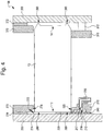
FIG. 4 is a cross-sectional view of the lubrication mechanism and infeed track. -
FIG. 5 is a detail view of a guide mounting plate of the infeed track. -
FIG. 6 is a detail view of an outer guide contacting surface of the lubrication mechanism. -
FIG. 7 is a detail view of the outer guide contacting surface ofFIG. 6 in which a can is shown contacting the outer guide contacting surface. -
FIG. 8 is a partial perspective view of a guide mounting plate illustrating a can in the infeed track. -
FIG. 9 is a side view of a lubrication mechanism according to an exemplary embodiment in which a can infeed is attached. -
FIG. 10 illustrates an exemplary embodiment of a machine line with a can infeed. -
FIG. 11 is a perspective view of a star wheel lubrication mechanism according to another embodiment. -
FIG. 12 is a front view of the star wheel lubrication mechanism ofFIG. 11 . -
FIG. 13 is a side view of the star wheel lubrication mechanism ofFIG. 11 . -
FIG. 14 is an exploded view of the star wheel lubrication mechanism ofFIG. 11 . -
FIG. 15 is a left side view of a guide member and frame member of a star wheel lubrication mechanism of an exemplary embodiment. -
FIG. 16 is a right side view of the guide member and frame member ofFIG. 15 . -
FIG. 17 is a detail view of the guide member and frame member ofFIG. 15 taken along line 17-17. -
FIG. 18 is a detail view of the guide member and frame member ofFIG. 15 taken along line 18-18. -
FIG. 19 is a detail view of the guide member and frame member ofFIG. 15 taken along line 19-19. -
FIG. 20A is a sectional view of a star wheel taken alongline 20A-20A inFIG. 13 that illustrates a vacuum chamber and a pressure chamber. -
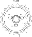
FIG. 20B is a sectional view of the star wheel ofFIG. 20A illustrating vacuum ports and pressure ports. -
FIG. 21 is a detail view taken alongdetail 21 fromFIG. 20A illustrating an air passage in a pocket of the star wheel. - The Figures illustrate a lubrication mechanism for article processing machines and machine arrangements (or machine lines) and related components. The article processing machine may process articles to perform a necking operation, or any other suitable operation (such as curling, flanging, etc.). An article may be a can, any suitable food or beverage container, jar, bottle or any other suitable article. The description below uses article and can interchangeably. The can has an open end, an opposite closed end, and a sidewall extending from the closed end. Alternatively, the can may be open at both ends. A top, lid or other closure may be added to the can after the forming process(es).
- For exemplary purposes only, the below description will describe the mechanisms and methods for use on a can. It will be recognized that any other type of article (such as that described above) may be used.
- Reference will now be made to the FIGURES.
-
Cans 10 are fed into a continuously rotating infeedstar wheel 20A (either from an infeed track, infeedlubricating mechanism track 100, or from a precedingtransfer star wheel 20, which may be part of amachine line 102. As shown in exemplaryFIG. 10 , an infeedstar wheel 20A is configured to pass acan 10 to a continuously rotatingtransfer star wheel 20, which is configured to then pass thecan 10 to an adjacentturret star wheel 21 or a turret or formingmachine 22 in themachine line 102. While thecan 10 is in theturret star wheel 21, a forming (necking, flanging, etc.) operation is performed on thecan 10. While theturret star wheel 21 is rotating with thecan 10, thecan 10 is then transferred from the formingturret star wheel 21 onto anothertransfer star wheel 20, forming/processturret star wheel 21, or adischarge track 130. In order to suitably lubricate an outside surface of an open end 12 (seeFIG. 4 ) portion of thecan 10, a lubrication mechanism is utilized in the machine line. Themachine line 102 shown is exemplary only. Any other suitable machine line configuration may be utilized. - In an embodiment, the
cans 10 are held in position on this infeedtransfer star wheel 20A (and other star wheels or turrets) using a pneumatic pressure differential or "suction" as it will be referred to. Thetransfer star wheels 20 are arranged to hold thecans 10 in position using suction applied to the outside surface of thecan 10 through a vacuum opening 24 inpockets 22, such as may be seen inFIG. 3 . Thetransfer star wheels suitable pockets 22 for holding thecans 10. For example, thetransfer star wheels pockets 22. The number ofpockets 22 in thetransfer star wheels - The
lubricating mechanism 100 shown inFigures 1-8 illustrates features of the present invention. Thelubricating mechanism 100 is configured to be used in die necking processes, or other suitable applications. The lubricating mechanism applies lubricant via a lubricant flow path 115 (seeFIG. 3 , for example) on an outer guide member 210 (sometimes referred to as a rail) that will reduce and contain mess generated by the lubrication process. Thelubricating mechanism 100 may be part of, before, or after thecan infeed 120. - The
lubricating mechanism 100 includes a curved track 110 (seeFIG. 5 , for example) that is either before or after the infeed mechanism, or is integrated into the infeed mechanism of the can processing machine line (such as for die necking). Thecurved track 110 of thelubricating mechanism 100 is configured to cause thecans 10 to roll primarily rather than slide through the section oftrack 110 where the lubricant is to be applied. The radius or curvature of thetrack 110 is configured to encourage rolling in the normal range of operating speeds of machine lines. - According to the example of
Figures 1 to 8 , the flow ofcans 10 leading into thetrack 110 may be controlled by a control mechanism (not shown). If thecans 10 experience significant loading in the track 110 (such as from thecans 10 being too closely spaced), the friction between thecans 10 may stop or prevent rotation of thecans 10. The control mechanism may include, as an example, astar wheel 20 arranged before thetrack 110 and configured to feedcans 10 into thelubrication track 110 to space out and control the flow ofcans 10 into the track. Any other suitable control mechanism may be utilized. - The length of the
track 110 is such that thecan 10 is able to rotate or roll a full revolution of thecan 10 in order to apply the lubricant. For example, the length of thetrack 110 is approximately at least two times the circumference of acan 10. Alternatively, the length of thetrack 110 may be shorter or longer. For example, the length of thetrack 110 may be less than a circumference of acan 10. - The
lubricating mechanism 100 includes first 200 and second 300 frame members (sometimes referred to as guide mounting plates) forming thetrack 110. On thefirst frame member 200, theouter guide member 210, aninner guide member 270, and a guide/wear plate 230 are attached. - The
outer guide member 210 is positioned on an outer radius portion of thecurved track 110 that includes a narrow contacting surface 220 (sometimes referred to as a narrow width) for contactingcans 10 near theiropen end 12. In other words, the width of theouter guide member 210 is sufficiently narrow so that only a minimum required amount of theupper end 12 of thecan 10 will contact theouter guide member 210 and, thus, thelubricant flow path 115, as can be seen inFIGS. 6 and7 . - The
outer guide member 210 includes one or more holes orpassageways 214 to transport lubricant from alubricant chamber 212 to the narrow contactingsurface 220, which is in contact withcans 10 near theopen end 12 of thecans 10 being conveyed along thetrack 110. The lubricant is configured to flow or slide down the outer guide member's 210flow path 115 without being sprayed into the air. Excess lubricant may be directed into a container (not shown) at a bottom of thelubricating mechanism 100. The container may be any container suitable to collect excess lubricant. - The inner guide member is attached to the first frame member and spaced apart from the outer guide member. The inner guide member is separated from the outer guide member a suitable distance to permit the diameter of the cans to be positioned therebetween (and therefore, in the track).
- As can be seen in
FIG. 4 , theinner guide member 270 includes aprofile surface 272 that has acutout portion 274 and anoutermost portion 278. Thecutout portion 274 is positioned on a portion of theprofile surface 272 closest to thefirst frame member 200. Thecutout portion 274 is set back from theoutermost portion 278 of theprofile surface 272 so the lubricant will not wipe off thecan 10 when thecan 10 rolls by. Theoutermost portion 278 of theprofile surface 272 may or may not contact the surface of thecan 10 as thecan 10 rolls through thetrack 110. - As best shown in
FIG. 7 , a guide/wear plate 230 is positioned adjacent theouter guide member 210 such that there is asmall gap 280 between the end of the can 10 (at the open end 12) and the track 110 (at the guide/wear plate 230). Alarger gap 290, shown inFIG. 4 , is provided between the end of the can 10 (at the open end 12) and thefirst frame member 200. The guide/wear plate 230 is configured to help provide thegap 280 so there is no contact between thecan 10 and remaining part of thetrack 110 where thetrack 110 would provide more resistance to rolling. - A
spacer 276, shown inFIG. 4 , may be provided between theinner guide member 270 and thefirst frame member 200 to position theinner guide member 270 as needed or to use aninner guide member 270 without acutout portion 274. Additionally or alternatively, a spacer 240 (or thermal insulator) may be positioned between theouter guide member 210 and thefirst frame member 200 to position theouter guide member 210 as needed (depending on, for example, the size of the can 10), such as shown inFIGS. 4 and7 . Thespacers cans 10 of varying height or to apply lubricant in varying locations from the end of thecan 10. - The
second frame member 300 includes anouter guide rail 310 andinner guide rail 370, as best shown inFIG. 4 . Spacers may be provided adjacent to thesecond frame member 300 to adjust for varying heights and profile shapes of thecans 10. Aspacer 312 may be positioned between thesecond frame member 300 and theouter guide rail 310. Aspacer 372 may be positioned between thesecond frame member 300 and theinner guide rail 310. Theframe member 300 has a profile shape such that alarger gap 390 is near theinner guide rail 310 and asmaller gap 380 is near theouter guide rail 310. - As shown in
FIGS. 4-5 , the axial location of thecan 10 may be positioned (via thespacers inner guide members inner rails 310, 370) to avoid any contact of theopen end 12 of thecan 10 near the inner radius (inside)portion 111A of thecurved track 110 to better promote rolling of thecans 10 rather than sliding. In other words, asmall gap 280 at the end of thecan 10 on theoutside portion 111B of the curve's centerline 111, and alarger gap 290 at theinside portion 111A of the curve's centerline 111, such as shown inFIGS. 4 and7 . Thecutout surface 274 of theinner guide member 270 on theinner radius 111A of thetrack 110 does not touch thecans 10 where lubricant is applied due to position and/or shape of theinner guide member 270. - In the
lubricating mechanism 100, lubricant is supplied to thetrack 110 viafittings 250 connected to the outer guide member 210 (FIGS. 1 and4 ). A tube or hose 255 (or another suitable device) connects a lubricant chamber (not shown) or supply to the fittings 250 (FIG. 1 ). The lubricant flows through thefittings 250, into a path in theouter guide member 210 and into the chamber 212 (which may include the wick 217), best shown inFIG. 4 . The lubricant is then configured to flow out of the openings orpassageways 214 out of theouter guide member 210 to flow down thetrack 110 along theoutside surface 220 of theouter guide member 210 in alubricant flow path 115 to lubricate thecan 10 near theopen end 12 of thecan 10. - The
lubricating mechanism 100 includes a plurality ofchambers 212 along the length of thetrack 110. Eachchamber 212 is provided with one or more holes (or passageways) 214 that link thechamber 212 to the outside of theouter guide member 210 to allow the lubricant to flow in theflow path 115. Thechamber 212 may include one or morefitting openings 216 to connect the fitting 250 to thechamber 212. - The
lubricating mechanism 100 may optionally include awick 217 positioned in thelubrication chamber 212, such as shown inFIG. 4 . Thewick 217 is configured to slow the flow of lubricant from thechamber 212 to thepassageway 214 and contactingsurface 220. Thewick 217 may comprise felt or any other suitable material. Thewick 217 is positioned in thelubrication chamber 212 such that thewick 217 does not directly contact thecan 10, which minimizes potential debris build up on thewick 217 and reduces the need to replace thewick 217. - As shown in
FIG. 1 , thelubricating mechanism 100 may also include aheater 260 to heat up and, thus, liquefy or reduce the viscosity of the lubricant. Theheater 260 may be attached directly onto theouter guide member 210. Theheater 260 may be attached to theouter guide member 210 via an adhesive, or any other suitable alternative. - The
lubricating mechanism 100 may also include athermal insulator 240 configured to reduce heat transfer from a heatedouter guide member 210 to adjacent parts, such as the first 200 andsecond frame members 300. Thethermal insulator 240 is best shown inFIG. 4 . Thethermal insulator 240 comprises a plastic composite, or any other suitable material. Thethermal insulator 240 may be utilized as a spacer to accommodate for varying sizes ofcans 10 in thetrack 110. - The
outer guide member 210 may further include acavity 218 with an o-ring 219, such as shown inFIGS. 6 and7 . The o-ring 219 is configured to provide a seal such that lubricant does not leak out of thechamber 212. - As best shown in
FIGS. 1 ,3 , and8 , thelubricating mechanism 100 can be quickly reconfigured to accommodate a different size can 100. In order to quickly reconfigure thelubricating mechanism 100, the disclosed embodiments of these structures are such that thelubricating mechanism 100 is formed in two halves (first 200 and second 300 frame members) so that at least one half can be moved relative to the other. The first 200 and second 300 frame members are mutually supported on one another by way of three shafts: two upper frame shafts (rods) 150 and one lower frame shaft (rod) 160. - As will be appreciated from the FIGURES showing these embodiments, one end of each of the
shafts fixed end 164 to one of the first 200 or second 300 frame members while the other end is configured to slide through acollar 154 which is fastened to the other of the first 200 or second 300 frame member. The collars comprise splitcollars 154 having one portion fastened to a housing/structural member of theframe members collars 154, theframe members shafts can 10 which is to be fed into thelubrication mechanism 100. Simply retightening thesplit collars 154 locks the first 200 and second 300 frame members in a suitable condition for feeding thecans 10 into thelubricating mechanism 100. - The
lubricating mechanism 100 can also be adjust to accommodatecans 10 of different diameter. Portions of thetrack 110 can be swapped out to be replaced with appropriately sized track components. For example, the inner 270 and outer 210 guide members, guide/wear plate 230, and outer 310 and inner 370 rails can be changed ifcans 10 with a different diameter are to be used in the machine apparatus or machine line. Thethermal insulator 240 and/orspacers - The
lubricating mechanism 100 may be connected to a can infeed 120. The can infeed 120 is configured to supply thecans 10 into thetrack 110 for lubrication to be applied.FIG. 9 illustrates one exemplary embodiment of acan infeed 120. - According to the embodiment of the invention as shown in
FIGS. 11-19 ,cans 10 are lubricated while being held inpockets 22 of a star wheel. Thecans 10 to be lubricated are held inseparate pockets 22 of the star wheel. The star wheel may be aninfeed star wheel 20A, or anyother star wheel 20 in amachine line 102. Thelubricating mechanism 400 includes alubricating track 414 coupled to or adjacent thestar wheel 20. - The
lubricating mechanism 400 includes a first frame member (first guide plate) 500 and a second frame member (second guide plate) 600. A first (or outer) guide member (or rail) 510 is attached to thefirst frame member 500 by screws 511 (FIGS. 15 and17 ) or any other suitable mechanism. Thefirst frame member 500 may further be attached to a mountingplate 515, aspacer 520 andheater cover 530, such as shown inFIG. 14 . - The
second frame member 600 is attached to a second guide member (or rail) 610 viascrews 602, or by any other suitable mechanism. Thefirst frame member 500 is attached or coupled to thesecond frame member 600 by one or more mountingrods 450, such as shown inFIG. 11 . - The
cans 10 to be lubricated are restrained radially betweenpockets 22 of thestar wheel 20 and the first andsecond guide members first guide member 510 supplies lubricant to thelubrication track 414 and thecans 10 viafittings 250 connected to thefirst guide member 510. A tube or hose 255 (FIG. 1 ) connects a lubricant supply to thefittings 250. The lubricant flows through thefittings 250, into alubricant passage 115 and out onto a surface of thefirst guide member 510. Thelubrication mechanism 400 may include awick 217 between the fitting 250 andpassage 115, such as shown inFIG. 19 . Thewick 217 may be made of felt or other suitable material. - The
cans 10 are restrained axially between the first andsecond frame members cans 10 in thepockets 22, the first andsecond frame members can 10 at a location or radius that is greater than thecenterline 11 of the path of thecan 10. For example,FIG. 12 illustrates thecenterline 11 path of thecans 10. Theframe members can 10 in thetrack 110 at a point outside of thecurve line 11 representing the centerline of the can's 10 path. Thefirst frame member 500 includes agroove 503 near the opening of thelubricant passage 115 for carrying away excess lubricant. Aguide contact surface 505 is arranged adjacent to thegroove 503 and is configured to contact a surface of thecan 10 being lubricated. - The
first guide member 510 has openings at thelubricant passage 115 through which the lubricant is deposited on the open end of thecan 10. The shape of the first andsecond guide members corresponding frame members lubrication bracket 420 is attached to the mountingplate 515 by screws or other suitable mechanism. Anoverflow trough 422, integrated intobracket 420, directs excess lubricant to overflowcontainer 424, which is also attached tobracket 420. Excess lubricant that exits thelubrication track 414 falls onto theoverflow trough 422, which is angled to direct the excess lubricant into theoverflow container 424. Excess lubricant will either flow to the end of thefirst guide member 510 and into theoverflow container 424, or flow over the edges or throughgrooves 503 provided in thefirst frame member 500 and down to theoverflow trough 422 and into theoverflow container 424. - When a can 10 passes through the
lubrication mechanism 400, thecan 10 will rotate in itsrespective pocket 22 and on the first andsecond guide members can 10. Thelubrication mechanism 400 utilizes friction to cause thecans 10 to rotate. The friction may be low and so an additional rotation inducing mechanism may be used. For example, a jet of air may be provided to enhance rotation of thecan 10 in thepocket 22. The jet of air may be supplied to thepockets 22 of thestar wheel 20 through air openings or passages 23 (FIGS. 11 and21 ) when the pockets 22 (and respective cans 10) are adjacent to thelubrication mechanism 400. Theopenings 23 may be angled to direct the air flow to further encourage rotation of thecan 10. The jet of air may be switched on and off or switched from air pressure to a vacuum to control thecans 10 as necessary by means of a valve apparatus. - Positive air pressure or negative pressure (vacuum) is supplied to the
pockets 22 of thestar wheel 20 through theopenings 23 via two chambers (810, 820) in the starwheel hub assembly 26 located inside thestar wheel 20. One ormore pressure ports 815 are connected to thepressure chamber 810 to provide air pressure. One ormore vacuum ports 825 are connected to thevacuum chamber 820 to provide a vacuum. Air is blown into thepockets 22 via theopenings 23 to encourage thecans 10 in thepockets 22 to rotate within the confines of thestar wheel pocket 22 and first andsecond guide members can 10 in thepocket 22 for the purpose of transportation. - As shown in
FIG. 12 , a blower pressure is applied to thecans 10 in the pockets starting at point A. The air pressure is continued in thepockets 22 while thestar wheel 20 rotates until apocket 22 reaches point B. At point B, a vacuum is applied to thepocket 22 to facilitatecan 10 transport in thestar wheel 20. The vacuum is continued until thecan 10 andpocket 22 reach point C. At point C, the vacuum is turned off so that thecan 10 may be transferred to an adjacent turret or star wheel. - As can be seen in
FIGS. 16 and19 , thefirst frame member 500 may include one ormore heaters 710. Theheaters 710 are attached to thefirst frame member 500 via aheater clamp 715 and screws 718. In the exemplary embodiment, aheater clamp 715 holds or clamps twoheaters 710 to thefirst frame member 500. - The
first frame member 500 may further include one or morethermal insulators FIGS. 16 and18 , athermal insulator 540 is attached to a rear surface of thefirst frame member 500. A secondthermal insulator 541 is attached to the front surface of thefirst frame member 500. Thethermal insulators first frame member 500 via ascrew 511 andwasher 512, or any other suitable mechanism. - As shown in
FIGS. 11 ,13 , and14 , thestar wheel 20 is connected to atransfer drive gear 475 via atransfer housing 470. Thestar wheel 20 is driven via thetransfer drive gear 475. - The
guide members wear plate 230, may comprise a hard, slow-wearing surface that will not require frequent replacement. For example, chrome plated steel may be used or any other suitable material. - It will be recognized that the lubricating mechanism may reduce the complexity and cost compared to a vacuum star wheel equipped with lubricating rollers. The lubricating mechanism also eliminates the need to replace a wick due to debris build up.
- As utilized herein, the terms "approximately," "about," "substantially", and similar terms are intended to have a broad meaning in harmony with the common and accepted usage by those of ordinary skill in the art to which the subject matter of this disclosure pertains. It should be understood by those of skill in the art who review this disclosure that these terms are intended to allow a description of certain features described and claimed without restricting the scope of these features to the precise numerical ranges provided. Accordingly, these terms should be interpreted as indicating that insubstantial or inconsequential modifications or alterations of the subject matter described and claimed are considered to be within the scope of the invention as recited in the appended claims.
- It should be noted that the term "exemplary" as used herein to describe various embodiments is intended to indicate that such embodiments are possible examples, representations, and/or illustrations of possible embodiments (and such term is not intended to connote that such embodiments are necessarily extraordinary or superlative examples).
- The terms "coupled," "connected," "attached," and the like as used herein mean the joining of two members directly or indirectly to one another. Such joining may be stationary (e.g., permanent) or moveable (e.g., removable or releasable). Such joining may be achieved with the two members or the two members and any additional intermediate members being integrally formed as a single unitary body with one another or with the two members or the two members and any additional intermediate members being attached to one another.
- References herein to the positions of elements (e.g., "top," "bottom," "above," "below," etc.) are merely used to describe the orientation of various elements in the FIGURES. It should be noted that the orientation of various elements may differ according to other exemplary embodiments, and that such variations are intended to be encompassed by the present disclosure.
- It is important to note that the construction and arrangement of the lubrication mechanism as shown in the various exemplary embodiments is illustrative only. Although only a few embodiments have been described in detail in this disclosure, those skilled in the art who review this disclosure will readily appreciate that many modifications are possible (e.g., variations in sizes, dimensions, structures, shapes and proportions of the various elements, values of parameters, mounting arrangements, use of materials, colors, orientations, etc.) without materially departing from the novel teachings and advantages of the subject matter described herein. For example, elements shown as integrally formed may be constructed of multiple parts or elements, the position of elements may be reversed or otherwise varied, and the nature or number of discrete elements or positions may be altered or varied. The order or sequence of any process or method steps may be varied or re-sequenced according to alternative embodiments. Other substitutions, modifications, changes and omissions may also be made in the design, operating conditions and arrangement of the various exemplary embodiments without departing from the scope of the present invention.
Claims (15)
- A lubricating mechanism (400) for a machine arrangement (102), comprising:a lubricating track (414), and an infeed mechanism (20A) configured to supply articles (10) to be processed to the machine arrangement (102), wherein the lubricating track (414) includes:an outer guide member (510) configured to contact open ends of the articles (10), the outer guide member (510) comprising a lubricant passage or chamber (212); andat least one opening (214) in the outer guide member (510) for passage of lubricant from the outer guide member (510) to a lubrication path (115) configured to be in contact with the articles (10) in the lubricating track (414) to apply the lubricant to the articles (10); anda starwheel (20) with a plurality of pockets (22) for holding the articles (10), wherein the articles (10) to be lubricated are located in separate pockets (22) of the starwheel (20), wherein the lubricating mechanism (400) is coupled to or adjacent the starwheel (20) such that the articles (10) located in the plurality of pockets (22) of the starwheel (20) receive lubrication from the lubricating track (414),wherein the lubricating mechanism (400) is configured so that the articles (10) rotate within their respective pockets (22) and on guide members (510,610) when passing through the lubrication track (414), andcharacterised in that the starwheel (20) comprises air passages (23) to provide air flow to the plurality of pockets (22) to rotate the articles (10) in the plurality of pockets (22).
- The lubricating mechanism of claim 1, further comprising a wick (217), positioned in the lubricant chamber (212) or between the lubrication path and fittings (250) of the outer guide member (510) configured to supply the lubricant to the outer guide member (510), wherein the wick (217) is positioned in the lubricant chamber (212) or between the lubricant path and fittings (250) such that the articles (10) do not directly contact the wick (217).
- The lubricating mechanism of claim 1, wherein the lubricating track (414) includes first (500) and second (600) frame members, and wherein the articles (10) are configured to extend between the first and second frame members.
- The lubricating mechanism of claim 1, further comprising at least one fitting connected to the outer guide member (510), the at least one fitting configured to supply the lubricant from a lubricant source to the lubricant chamber.
- The lubricating mechanism of claim 3,
wherein the first frame member (500) includes the outer guide member (510), and
wherein the outer guide member includes a heater (710) configured to heat the lubricant in the lubricant chamber or passage. - The lubricating mechanism of claim 5, further comprising a thermal insulator (540) positioned between the first frame member and the outer guide member, the thermal insulator configured to reduce heat transfer from a heated outer guide member (510) to the first frame member.
- The lubricating mechanism of claim 1, wherein each of the plurality of pockets (22) receives positive air pressure or vacuum depending on a current angular position of the starwheel (20) and each of the plurality of pockets (22).
- The lubricating mechanism of claim 7, wherein the positive air pressure is supplied to at least one of the plurality of pockets (22) when the at least one of the plurality of pockets (22) is adjacent the lubricating track (414), and
wherein the vacuum pressure is supplied to the at least one of the plurality of pockets (22) when the at least one of the plurality of pockets (22) is positioned away from the lubricating track (414). - The lubricating mechanism of claim 2:wherein the wick (217) is configured to supply the lubricant to the lubrication path (115),wherein the lubrication path (115) on the outer guide member extends along the lubricating track (414), andwherein the articles (10) contact lubricant in the lubrication path (115) when rolling through the lubricating track (414) without contacting the wick (217).
- The lubricating mechanism of claim 9, further comprising a transfer starwheel (20) coupled to the infeed mechanism (20A) and configured such that articles exiting the infeed mechanism (20A) move into corresponding pockets (22) in the transfer starwheel (20).
- A method of lubricating an article (10) in a machine arrangement (102), comprising:providing a lubricating track (414);applying a lubricant to a lubrication path (115) on the lubricating track (414) from a lubricant chamber or passage (212);holding at least one article (10) in at least one of a plurality of pockets (22) of a starwheel (20), wherein the articles (10) to be lubricated are located in separate pockets (22) of the starwheel (20), the starwheel (20) comprising air passages (23); androtating the at least one article (10) within the at least one of the plurality of pockets (22) and on guide members (510,610) when passing through the lubricating track (414) or within a lubrication mechanism (400) so that the lubricant transfers to an open end (12) of the at least one article as the at least one article contacts the lubrication path on the lubricating track,characterised in that the rotating includes providing an air flow, with an air passage of the starwheel (20), to the at least one of the plurality of pockets (22) to rotate the at least one article (10) in the at least one of the plurality of pockets (22).
- The method of claim 11, wherein the lubricant chamber or passage includes a wick (217), and wherein the at least one article (10) does not directly contact the wick (217).
- The method of claim 11, further comprising heating the lubricant in the lubricant chamber.
- The method of claim 11, wherein the lubricating track (414) includes first (500) and second (600) frame members, and wherein the articles (10) are configured to extend between the first and second frame members.
- The method of claim 11, wherein each of the plurality of pockets (22) receives positive air pressure or vacuum depending on a current angular position of the starwheel (20) and each of the plurality of pockets (22).
Priority Applications (1)
| Application Number | Priority Date | Filing Date | Title |
|---|---|---|---|
| PL10705733T PL2401092T3 (en) | 2009-02-26 | 2010-02-23 | Lubrication mechanism for can processing machine |
Applications Claiming Priority (2)
| Application Number | Priority Date | Filing Date | Title |
|---|---|---|---|
| US20242709P | 2009-02-26 | 2009-02-26 | |
| PCT/US2010/024988 WO2010099081A1 (en) | 2009-02-26 | 2010-02-23 | Lubrication mechanism for can processing machine |
Publications (2)
| Publication Number | Publication Date |
|---|---|
| EP2401092A1 EP2401092A1 (en) | 2012-01-04 |
| EP2401092B1 true EP2401092B1 (en) | 2017-09-20 |
Family
ID=42167430
Family Applications (6)
| Application Number | Title | Priority Date | Filing Date |
|---|---|---|---|
| EP10707725.7A Active EP2401096B1 (en) | 2009-02-26 | 2010-02-22 | Self compensating sliding air valve mechanism |
| EP10705250.8A Active EP2401093B1 (en) | 2009-02-26 | 2010-02-22 | Dual ram assembly for necker machine |
| EP10705733.3A Active EP2401092B1 (en) | 2009-02-26 | 2010-02-23 | Lubrication mechanism for can processing machine |
| EP10705734.1A Active EP2401094B1 (en) | 2009-02-26 | 2010-02-23 | Key for quick change for turret pocket |
| EP10705762.2A Active EP2401216B1 (en) | 2009-02-26 | 2010-02-24 | Quick change for transfer starwheel |
| EP10705760.6A Active EP2401095B1 (en) | 2009-02-26 | 2010-02-24 | Can processing machine with cantilever design |
Family Applications Before (2)
| Application Number | Title | Priority Date | Filing Date |
|---|---|---|---|
| EP10707725.7A Active EP2401096B1 (en) | 2009-02-26 | 2010-02-22 | Self compensating sliding air valve mechanism |
| EP10705250.8A Active EP2401093B1 (en) | 2009-02-26 | 2010-02-22 | Dual ram assembly for necker machine |
Family Applications After (3)
| Application Number | Title | Priority Date | Filing Date |
|---|---|---|---|
| EP10705734.1A Active EP2401094B1 (en) | 2009-02-26 | 2010-02-23 | Key for quick change for turret pocket |
| EP10705762.2A Active EP2401216B1 (en) | 2009-02-26 | 2010-02-24 | Quick change for transfer starwheel |
| EP10705760.6A Active EP2401095B1 (en) | 2009-02-26 | 2010-02-24 | Can processing machine with cantilever design |
Country Status (5)
| Country | Link |
|---|---|
| US (8) | US8297098B2 (en) |
| EP (6) | EP2401096B1 (en) |
| ES (5) | ES2584914T3 (en) |
| PL (6) | PL2401093T3 (en) |
| WO (6) | WO2010099067A1 (en) |
Families Citing this family (49)
| Publication number | Priority date | Publication date | Assignee | Title |
|---|---|---|---|---|
| US8297098B2 (en) * | 2009-02-26 | 2012-10-30 | Belvac Production Machinery, Inc. | Dual ram assembly for necker machine |
| DE102011113563A1 (en) * | 2011-09-19 | 2013-03-21 | Oerlikon Trading Ag, Trübbach | Carousel carriage for vacuum treatment plant |
| ES1120230Y (en) * | 2011-11-09 | 2014-11-20 | Belvac Production Machinery Inc | VESSEL CONFORMATION DEVICE |
| JP2015518546A (en) * | 2012-03-08 | 2015-07-02 | ベルヴァック・プロダクション・マシーナリー・インコーポレイテッドBelvac Production Machinery,Inc. | Cam follower device |
| CN102689235B (en) * | 2012-05-23 | 2014-06-25 | 浙江摩多巴克斯汽配有限公司 | Multi-station pipe end machining equipment |
| US20130321795A1 (en) * | 2012-05-31 | 2013-12-05 | Belvac Production Machinery, Inc. | Defect tester |
| CN102909580B (en) * | 2012-08-23 | 2015-04-01 | 联德机械(杭州)有限公司 | Sliding valve tool for twin-screw compressor and sliding valve processing method |
| CN103111845A (en) * | 2013-02-26 | 2013-05-22 | 深圳市神拓机电设备有限公司 | Disc type carrying roller sealing assembling equipment |
| US20140253718A1 (en) * | 2013-03-11 | 2014-09-11 | Rexam Beverage Can Company | Method and apparatus for necking and flanging a metallic bottle |
| WO2015076823A1 (en) | 2013-11-22 | 2015-05-28 | Silgan Containers Llc | Can-making apparatus with trimmer chute |
| EP3110576B1 (en) | 2014-02-27 | 2022-04-27 | Belvac Production Machinery, Inc. | Recirculation systems and methods for can and bottle making machinery |
| JP2017519949A (en) * | 2014-05-06 | 2017-07-20 | ジーマ ソチエタ ペル アツィオニGima S.P.A | Swivel distributor |
| CN104259508A (en) * | 2014-09-11 | 2015-01-07 | 无锡振华机械有限公司 | Boring machine allowing simultaneous machining of more than two workpieces |
| CN104227461A (en) * | 2014-09-11 | 2014-12-24 | 无锡振华机械有限公司 | Clamping compensation device for use in machining of plurality of workpieces |
| US9655269B2 (en) | 2015-05-12 | 2017-05-16 | Honeywell International Inc. | Support system for printed board assemblies |
| CN105215775A (en) * | 2015-10-18 | 2016-01-06 | 滁州品之达电器科技有限公司 | For the material transfer wheel assembly in air-actuated feeding mechanism |
| WO2018012040A1 (en) * | 2016-07-11 | 2018-01-18 | ユニバーサル製缶株式会社 | Can molding device |
| JP2018012140A (en) * | 2016-07-11 | 2018-01-25 | ユニバーサル製缶株式会社 | Can forming apparatus |
| JP6914125B2 (en) * | 2016-07-11 | 2021-08-04 | ユニバーサル製缶株式会社 | Can molding equipment |
| US11085885B2 (en) * | 2017-01-19 | 2021-08-10 | Aegion Coating Services, Llc | Pipe joint inspection |
| DE102017112771A1 (en) * | 2017-06-09 | 2018-12-13 | Mall + Herlan Schweiz Ag | Machining device and method with relatively moving tools |
| DE102017120703B4 (en) * | 2017-09-07 | 2026-05-07 | Krones Aktiengesellschaft | Device for feeding lids to a can sealer |
| JP7039943B2 (en) * | 2017-11-14 | 2022-03-23 | 東洋製罐株式会社 | Bottle can manufacturing equipment and bottle can manufacturing method |
| US10752448B2 (en) | 2018-05-02 | 2020-08-25 | Belvac Production Machinery, Inc. | Devices and methods for can and bottle making recirculation systems |
| WO2019217614A1 (en) * | 2018-05-11 | 2019-11-14 | Stolle Machinery Company, Llc | Quick change transfer assembly |
| CN115958118B (en) | 2018-05-11 | 2026-06-19 | 斯多里机械有限责任公司 | Quick change tool assembly |
| US11565303B2 (en) | 2018-05-11 | 2023-01-31 | Stolle Machinery Company, Llc | Rotary manifold |
| US11370015B2 (en) | 2018-05-11 | 2022-06-28 | Stolle Machinery Company, Llc | Drive assembly |
| EP3790822B1 (en) * | 2018-05-11 | 2025-02-26 | Stolle Machinery Company, LLC | Process shaft tooling assembly |
| CN112105916B (en) | 2018-05-11 | 2024-01-02 | 斯多里机械有限责任公司 | Feed into components Full inspection of components |
| CN112105571B (en) | 2018-05-11 | 2022-04-19 | 斯多里机械有限责任公司 | Quick change feature for a feed-in assembly |
| CA3115929A1 (en) | 2018-10-11 | 2020-04-16 | Belvac Production Machinery, Inc. | Versatile base for can necking system |
| CN109262894B (en) * | 2018-11-13 | 2021-01-22 | 江苏斯益诺新材料科技有限公司 | Auxiliary treatment equipment for recycling PET plastic bottles and using method thereof |
| US11420242B2 (en) | 2019-08-16 | 2022-08-23 | Stolle Machinery Company, Llc | Reformer assembly |
| US11666961B2 (en) * | 2020-05-28 | 2023-06-06 | Stolle Machinery Company, Llc | Cam follower assembly for can bodymaker and can bodymaker including same |
| US11338351B2 (en) * | 2020-05-28 | 2022-05-24 | Stolle Machinery Company, Llc | Cam driven multi-output bodymaker |
| US11440078B2 (en) | 2020-09-15 | 2022-09-13 | Stolle Machinery Company, Llc | Drive assembly |
| CN112156933B (en) * | 2020-09-23 | 2021-12-07 | 王敬坤 | Keyway processing equipment that archaize building used |
| CN112024199B (en) * | 2020-09-29 | 2021-08-31 | 大连万盛合机电设备有限公司 | Automobile wheel hub intelligent manufacturing is with clamping device that sprays paint |
| CN112276150A (en) * | 2020-10-23 | 2021-01-29 | 江艳 | Automatic perforating device of batch button |
| CN112536620A (en) * | 2020-11-18 | 2021-03-23 | 天津飞悦智能装备有限公司 | But height-adjusting's aircraft control drive wheel processing frock |
| KR102973702B1 (en) * | 2021-03-04 | 2026-06-05 | 수드로닉 아게 | Device for producing tear covers |
| CN112896953A (en) * | 2021-03-12 | 2021-06-04 | 苏州斯莱克精密设备股份有限公司 | Equipment for realizing high-speed neck forming of pop-top can by multi-channel feeding |
| CN113023266B (en) * | 2021-03-12 | 2025-08-26 | 苏州斯莱克精密设备股份有限公司 | Equipment that achieves high-speed and stable neck forming of cans through multiple repositioning |
| US11786956B2 (en) | 2021-05-14 | 2023-10-17 | Stolle Machinery Company, Llc | System and method for automated low-speed positioning of a can necking machine |
| JP2024526788A (en) * | 2021-07-15 | 2024-07-19 | ベルヴァック・プロダクション・マシーナリー・インコーポレイテッド | Servo Control Machine Line |
| DE102022118509A1 (en) * | 2022-07-25 | 2024-01-25 | Khs Gmbh | Arrangement comprising a guide rail of a transport device for transporting containers and a lubricating device, and method for lubricating a guide rail |
| WO2026017520A1 (en) * | 2024-07-15 | 2026-01-22 | Societe Des Produits Nestle S.A. | Apparatus for engraving of pre-portioned container |
| US20260166618A1 (en) * | 2024-12-13 | 2026-06-18 | Stolle Machinery Company, Llc | Adjustable pusher arrangement for metal container forming and cutting machines |
Family Cites Families (100)
| Publication number | Priority date | Publication date | Assignee | Title |
|---|---|---|---|---|
| GB190923528A (en) * | 1909-10-14 | 1910-12-14 | Frederick Gustavous Ginzler | Improvements in Spinning and Seaming Machines for use in the Manufacture of Preserve Tins and the like. |
| US1673236A (en) * | 1913-11-28 | 1928-06-12 | American Can Co | Topping mechanism for filled-can-closing machines |
| GB1042506A (en) | 1962-05-29 | 1966-09-14 | Hopkinsons Ltd | Improvements relating to parallel slide valves |
| US3378285A (en) | 1966-03-14 | 1968-04-16 | William C. Staley | Keying device |
| US3418837A (en) | 1967-01-26 | 1968-12-31 | Miller Thomas Corp | Self-lubricated and sanitary drive means for can flanger and the like |
| US3418817A (en) * | 1967-09-12 | 1968-12-31 | Rusche Fredric | Method of installing liner for thin wall pipe pile |
| US3581542A (en) | 1969-02-03 | 1971-06-01 | Continental Can Co | Apparatus for and method of necking in end portions of tubular members |
| US3682296A (en) * | 1970-03-04 | 1972-08-08 | Eric S Buhayar | Apparatus for printing container sidewalls |
| US3797429A (en) * | 1973-02-22 | 1974-03-19 | United Can Co | Method and apparatus for necking and flanging can bodies |
| US3913366A (en) * | 1974-05-10 | 1975-10-21 | Gulf & Western Mfg Co | Apparatus for necking-in can bodies |
| US3983729A (en) * | 1975-02-03 | 1976-10-05 | National Can Corporation | Method and apparatus for necking and flanging containers |
| US3971186A (en) * | 1975-08-13 | 1976-07-27 | Electronic Memories And Magnetics Corporation | Wedge lock unit |
| US4298904A (en) * | 1979-12-17 | 1981-11-03 | The Boeing Company | Electronic conduction cooling clamp |
| US4278711A (en) * | 1980-01-14 | 1981-07-14 | Ball Corporation | Apparatus and method for the lubrication of cans |
| US4318157A (en) * | 1980-06-06 | 1982-03-02 | Control Data Corporation | Apparatus for mounting circuit cards |
| US4402202A (en) * | 1981-07-01 | 1983-09-06 | Gombas Laszlo A | Method and apparatus for roll flanging container bodies |
| US4446714A (en) * | 1982-02-08 | 1984-05-08 | Cvacho Daniel S | Methods of necking-in and flanging tubular can bodies |
| US4513595A (en) * | 1982-02-08 | 1985-04-30 | Cvacho Daniel S | Methods of necking-in and flanging tubular can bodies |
| US4480287A (en) * | 1982-12-27 | 1984-10-30 | Raytheon Company | Module retainer apparatus |
| US4519232A (en) * | 1982-12-27 | 1985-05-28 | National Can Corporation | Method and apparatus for necking containers |
| US4774839A (en) | 1982-12-27 | 1988-10-04 | American National Can Company | Method and apparatus for necking containers |
| US5497900A (en) | 1982-12-27 | 1996-03-12 | American National Can Company | Necked container body |
| US4547645A (en) | 1983-02-01 | 1985-10-15 | American Can Company | Material handling method and apparatus therefor |
| US4519595A (en) * | 1984-07-10 | 1985-05-28 | N.C.A. Co., Ltd. | Apparatus for unwinding fabric from a roll |
| US5590558A (en) | 1985-03-15 | 1997-01-07 | Weirton Steel Corporation | Draw-processing of can bodies for sanitary can packs |
| US4671093A (en) * | 1985-09-13 | 1987-06-09 | Van Dam Machine Corporation | Transfer assembly for tube printing apparatus |
| US4697414A (en) | 1985-12-09 | 1987-10-06 | The Garrett Corporation | Lubrication apparatus |
| JPH0239633Y2 (en) * | 1986-02-25 | 1990-10-24 | ||
| ATE47117T1 (en) * | 1986-05-23 | 1989-10-15 | Uhlmann Maschf Josef | DEVICE FOR RECEIVING, TRANSFERRING AND DELIVERING FLAT PACKAGING OBJECTS ON PACKAGING MACHINES. |
| US4819713A (en) * | 1987-04-23 | 1989-04-11 | Calmark Corporation | Retainer for electronic modules |
| US4824303A (en) | 1987-09-24 | 1989-04-25 | Rexnord Inc. | Locking wedge apparatus for printed circuit board |
| US5010444A (en) * | 1987-11-13 | 1991-04-23 | Radstone Technology Limited | Rack mounted circuit board |
| US5018379A (en) | 1989-02-22 | 1991-05-28 | Mitsubishi Metal Corporation | Apparatus and method for crimping end of can body |
| DE3908394C1 (en) | 1989-03-15 | 1989-12-21 | Karges-Hammer-Maschinen Gmbh & Co Kg, 3300 Braunschweig, De | Apparatus for making can bodies |
| US5023112A (en) | 1989-04-11 | 1991-06-11 | Adolph Coors Company | Apparatus and method for applying a coating to a can body |
| DE4010115C1 (en) | 1990-02-05 | 1991-10-24 | Finzer, Heinz, 7880 Bad Saeckingen, De | |
| DE4023771A1 (en) | 1990-07-26 | 1992-01-30 | Rainer Dipl Ing Daumann | Multi-spindle automatic lathe |
| US5224016A (en) * | 1990-05-31 | 1993-06-29 | Calmark Corporation | Retainer for electronic modules |
| USH906H (en) | 1990-06-04 | 1991-04-02 | The United States Of America As Represented By The United States Department Of Energy | Wedge assembly for electrical transformer component spacing |
| JP2890899B2 (en) | 1990-06-11 | 1999-05-17 | 三菱マテリアル株式会社 | Wax coating method and coating device |
| DE4028003A1 (en) * | 1990-09-04 | 1992-03-05 | Messerschmitt Boelkow Blohm | CLAMPING ELEMENT TO HOLD ELECTRONIC CARD |
| US5242497A (en) | 1991-10-29 | 1993-09-07 | Sweetheart Cup Company Inc. | Applicator systems for applying a localized amount of coating material to top edges of containers |
| US5344252A (en) | 1992-02-12 | 1994-09-06 | Hiroshi Kakimoto | Key for coupling driving and driven members together |
| US5249449A (en) * | 1992-04-23 | 1993-10-05 | Reynolds Metals Company | Can necking apparatus with spindle containing pressurizing gas reservoir |
| US5282375A (en) | 1992-05-15 | 1994-02-01 | Reynolds Metals Company | Spin flow necking apparatus and method of handling cans therein |
| US5220993A (en) * | 1992-10-26 | 1993-06-22 | R. A. Jones & Co. Inc. | Multiple lane pouch drop-off |
| US5407297A (en) * | 1993-02-24 | 1995-04-18 | Eg&G Birtcher, Inc. | Circuit board retainer having a spring body member |
| US5485353A (en) * | 1993-02-26 | 1996-01-16 | Eg&G Birtcher, Inc. | Retainer assembly |
| US5718030A (en) | 1994-07-18 | 1998-02-17 | Langmack Company International | Method of dry abrasive delabeling of plastic and glass bottles |
| GB9414540D0 (en) | 1994-07-19 | 1994-09-07 | At & T Global Inf Solution | Apparatus for assessing the condition of a bank note |
| US5555756A (en) * | 1995-01-24 | 1996-09-17 | Inland Steel Company | Method of lubricating steel strip for cold rolling, particularly temper rolling |
| US5676006A (en) * | 1995-03-08 | 1997-10-14 | Delaware Capital Formation, Inc. | Preloaded-cam follower ram assembly for reshaping containers |
| US5611231A (en) | 1995-04-20 | 1997-03-18 | Capital Formation Inc | Modular base can processing equipment |
| WO1997037786A1 (en) | 1996-04-04 | 1997-10-16 | Bowlin Geoffrey R | Modular can necking apparatus |
| US5678445A (en) * | 1996-05-01 | 1997-10-21 | Coors Brewing Company | Apparatus for necking can bodies |
| US5775161A (en) | 1996-11-05 | 1998-07-07 | American National Can Co. | Staggered die method and apparatus for necking containers |
| US5771807A (en) | 1996-11-13 | 1998-06-30 | Presstek, Inc. | Reusable mandrel for use in a printing press |
| US5768931A (en) * | 1996-12-13 | 1998-06-23 | Gombas; Laszlo A. | Article processing machine |
| JP3402988B2 (en) | 1997-01-31 | 2003-05-06 | 三洋電機株式会社 | Up and down cam mechanism of electronic component mounting device |
| US5755130A (en) * | 1997-03-07 | 1998-05-26 | American National Can Co. | Method and punch for necking cans |
| JP3284957B2 (en) * | 1998-01-27 | 2002-05-27 | 村田機械株式会社 | Punch press |
| JP2000346238A (en) | 1999-06-02 | 2000-12-15 | Tokyo Electron Ltd | valve |
| US6722494B2 (en) * | 1999-12-16 | 2004-04-20 | Zuiko Corporation | Method and device for transportation |
| US6285564B1 (en) * | 2000-03-24 | 2001-09-04 | Keystone Electronics Packaging, Inc. | Circuit card retainer assembly |
| DE10025405C2 (en) | 2000-05-23 | 2003-03-20 | Gert Dieter Hohenoecker | Component for positive and non-positive shaft-hub connection |
| JP4372318B2 (en) * | 2000-07-19 | 2009-11-25 | Sriスポーツ株式会社 | Golf ball |
| JP2002310178A (en) | 2001-04-16 | 2002-10-23 | Honda Motor Co Ltd | Combination key, work jig used for the key, and method of using the key |
| US6632379B2 (en) * | 2001-06-07 | 2003-10-14 | National Institute For Materials Science | Oxynitride phosphor activated by a rare earth element, and sialon type phosphor |
| US6694843B2 (en) * | 2001-11-05 | 2004-02-24 | Intech Corporation | Preloaded shock absorbing bushing and cam follower |
| US6637247B2 (en) * | 2001-11-06 | 2003-10-28 | Delaware Capital Formation, Inc. | Air manifold |
| ITPR20030013A1 (en) | 2003-02-19 | 2004-08-20 | Lanfranchi Srl | STAR CONVEYOR FOR FEEDING OR EVACUATING EMPTY PLASTIC CONTAINERS OR BOTTLES TO A MACHINE AND STRAIGHTENING AND ALIGNING MACHINE INCORPORATING SAID STAR CONVEYOR. |
| DE10319302B3 (en) | 2003-04-29 | 2004-08-12 | Wacker-Chemie Gmbh | Gas-tight disc slider for controlling high purity polysilicon granule flow stream from turbulence layer reactor with slider plate and valve seat provided with silicon or quartz glass surface |
| US6874971B2 (en) | 2003-07-08 | 2005-04-05 | Freeman Capital Company | Connector for tube and connected tubular structure |
| US6978636B2 (en) * | 2003-09-16 | 2005-12-27 | Interdynamics, Inc. | Device for measuring pressure in automobile air conditioner and charging same with refrigerant and method of same |
| DK1673183T3 (en) | 2003-10-15 | 2008-02-11 | Crown Packaging Technology Inc | CAN MANUFACTURE |
| JP2005329424A (en) * | 2004-05-19 | 2005-12-02 | Mitsubishi Materials Corp | Bottle can manufacturing equipment |
| JP2005329434A (en) | 2004-05-20 | 2005-12-02 | Koike Sanso Kogyo Co Ltd | Electrode for plasma torch |
| US7283867B2 (en) * | 2004-06-10 | 2007-10-16 | Ndi Medical, Llc | Implantable system and methods for acquisition and processing of electrical signals from muscles and/or nerves and/or central nervous system tissue |
| US7418852B2 (en) | 2004-11-18 | 2008-09-02 | Belvac Production Machinery, Inc. | Quick change over apparatus for machine line |
| ATE392381T1 (en) | 2004-12-23 | 2008-05-15 | Crown Packaging Technology Inc | HANDLING DEVICE FOR MULTI-STEP PROCESS |
| ITBO20050254A1 (en) | 2005-04-19 | 2005-07-19 | Azionaria Costruzioni Acma Spa | EQUIPMENT FOR THE TREATMENT OF CONTAINERS WITH LIQUID OR POWDER PRODUCTS |
| US7483271B2 (en) * | 2005-05-19 | 2009-01-27 | Bae Systems Information And Electronic Systems Integration Inc. | High density card retention device |
| US7886894B2 (en) | 2006-03-31 | 2011-02-15 | Belvac Production Machinery, Inc. | Method and apparatus for bottle recirculation |
| US7464573B2 (en) | 2006-03-31 | 2008-12-16 | Belvac Production Machinery, Inc. | Apparatus for curling an article |
| US7530445B2 (en) | 2006-03-31 | 2009-05-12 | Belvac Production Machinery, Inc. | Long stroke slide assemblies |
| US7963139B2 (en) * | 2006-03-31 | 2011-06-21 | Belvac Production Machinery, Inc. | Apparatus for can expansion |
| US7905130B2 (en) | 2006-03-31 | 2011-03-15 | Belvac Production Machinery, Inc. | Apparatus for threading cans |
| US7818987B2 (en) | 2006-03-31 | 2010-10-26 | Belvac Production Machinery, Inc. | Method and apparatus for trimming a can |
| WO2008111552A1 (en) * | 2007-03-09 | 2008-09-18 | Mitsubishi Materials Corporation | Can manufacturing device and can manufacturing method |
| US7568573B2 (en) | 2007-09-21 | 2009-08-04 | Belvac Production Machinery, Inc. | High speed selective container sorter |
| WO2009100972A1 (en) * | 2008-02-14 | 2009-08-20 | Crown Packaging Technology, Inc. | Apparatus and method for manufacturing metal containers |
| GB0806884D0 (en) | 2008-04-16 | 2008-05-21 | Meadwestvaco Packaging Systems | Article orientating device |
| US7997111B2 (en) * | 2008-04-24 | 2011-08-16 | Crown, Packaging Technology, Inc. | Apparatus for rotating a container body |
| US7770425B2 (en) * | 2008-04-24 | 2010-08-10 | Crown, Packaging Technology, Inc. | Container manufacturing process having front-end winder assembly |
| US8464567B2 (en) * | 2008-04-24 | 2013-06-18 | Crown Packaging Technology, Inc. | Distributed drives for a multi-stage can necking machine |
| US7784319B2 (en) * | 2008-04-24 | 2010-08-31 | Crown, Packaging Technology, Inc | Systems and methods for monitoring and controlling a can necking process |
| US8245551B2 (en) * | 2008-04-24 | 2012-08-21 | Crown Packaging Technology, Inc. | Adjustable transfer assembly for container manufacturing process |
| US8045332B2 (en) * | 2008-07-23 | 2011-10-25 | Harris Corporation | Multi-direction wedge clamp |
| US8375759B2 (en) * | 2008-10-20 | 2013-02-19 | Crown Packaging Technology, Inc. | Bridge turret transfer assembly |
| US8297098B2 (en) | 2009-02-26 | 2012-10-30 | Belvac Production Machinery, Inc. | Dual ram assembly for necker machine |
-
2009
- 2009-07-10 US US12/501,135 patent/US8297098B2/en active Active
- 2009-07-10 US US12/501,153 patent/US8627705B2/en active Active
-
2010
- 2010-02-22 PL PL10705250T patent/PL2401093T3/en unknown
- 2010-02-22 WO PCT/US2010/024926 patent/WO2010099067A1/en not_active Ceased
- 2010-02-22 WO PCT/US2010/024941 patent/WO2010099069A1/en not_active Ceased
- 2010-02-22 EP EP10707725.7A patent/EP2401096B1/en active Active
- 2010-02-22 ES ES10707725.7T patent/ES2584914T3/en active Active
- 2010-02-22 EP EP10705250.8A patent/EP2401093B1/en active Active
- 2010-02-22 PL PL10707725.7T patent/PL2401096T3/en unknown
- 2010-02-23 PL PL10705733T patent/PL2401092T3/en unknown
- 2010-02-23 EP EP10705733.3A patent/EP2401092B1/en active Active
- 2010-02-23 WO PCT/US2010/024988 patent/WO2010099081A1/en not_active Ceased
- 2010-02-23 US US12/710,825 patent/US8616559B2/en active Active
- 2010-02-23 PL PL10705734T patent/PL2401094T3/en unknown
- 2010-02-23 ES ES10705733.3T patent/ES2644214T3/en active Active
- 2010-02-23 EP EP10705734.1A patent/EP2401094B1/en active Active
- 2010-02-23 US US12/710,808 patent/US8464836B2/en active Active
- 2010-02-23 WO PCT/US2010/024992 patent/WO2010099082A1/en not_active Ceased
- 2010-02-23 ES ES10705734.1T patent/ES2614645T3/en active Active
- 2010-02-24 WO PCT/US2010/025182 patent/WO2010099165A2/en not_active Ceased
- 2010-02-24 US US12/711,891 patent/US8733146B2/en active Active
- 2010-02-24 ES ES10705762.2T patent/ES2490244T3/en active Active
- 2010-02-24 PL PL10705760T patent/PL2401095T3/en unknown
- 2010-02-24 ES ES10705760.6T patent/ES2598478T3/en active Active
- 2010-02-24 EP EP10705762.2A patent/EP2401216B1/en active Active
- 2010-02-24 EP EP10705760.6A patent/EP2401095B1/en active Active
- 2010-02-24 US US12/711,878 patent/US20100212393A1/en not_active Abandoned
- 2010-02-24 WO PCT/US2010/025192 patent/WO2010099171A1/en not_active Ceased
- 2010-02-24 PL PL10705762T patent/PL2401216T3/en unknown
- 2010-02-24 US US12/711,864 patent/US8464856B2/en active Active
-
2013
- 2013-02-12 US US13/764,835 patent/US9095888B2/en active Active
Non-Patent Citations (1)
| Title |
|---|
| None * |
Also Published As
Similar Documents
| Publication | Publication Date | Title |
|---|---|---|
| US8464836B2 (en) | Lubrication applicator for can processing machine | |
| CN113226773B (en) | Inker assembly including oscillating roller for can body decorator | |
| RU2191699C2 (en) | Continuous apparatus for decorating cylindrical vessels (versions) | |
| KR101867130B1 (en) | Forming apparatus | |
| EP2928628B1 (en) | Transfer starwheel assembly | |
| US5401938A (en) | Rotary drop former with electrical inductive heater | |
| EP3452379A1 (en) | Labeling machine for containers | |
| EP3151979A1 (en) | System for spraying the inside of can bodies | |
| HK1166037B (en) | Lubrication mechanism for can processing machine | |
| HK1166037A (en) | Lubrication mechanism for can processing machine | |
| TWI235207B (en) | Wide rolling-press arrangement for an unwrinkled guide of bands | |
| AU2016318469A1 (en) | Smoothing roller assembly | |
| US11033950B2 (en) | Method for producing a gas or liquid tank | |
| US20130266904A1 (en) | Lip Rolling Machine With Rotated Oven Guide Bar | |
| AU2016232556A1 (en) | Mandrel wheel for producing packagings |
Legal Events
| Date | Code | Title | Description |
|---|---|---|---|
| PUAI | Public reference made under article 153(3) epc to a published international application that has entered the european phase |
Free format text: ORIGINAL CODE: 0009012 |
|
| 17P | Request for examination filed |
Effective date: 20110908 |
|
| AK | Designated contracting states |
Kind code of ref document: A1 Designated state(s): AT BE BG CH CY CZ DE DK EE ES FI FR GB GR HR HU IE IS IT LI LT LU LV MC MK MT NL NO PL PT RO SE SI SK SM TR |
|
| DAX | Request for extension of the european patent (deleted) | ||
| REG | Reference to a national code |
Ref country code: HK Ref legal event code: DE Ref document number: 1166037 Country of ref document: HK |
|
| 17Q | First examination report despatched |
Effective date: 20131017 |
|
| GRAP | Despatch of communication of intention to grant a patent |
Free format text: ORIGINAL CODE: EPIDOSNIGR1 |
|
| STAA | Information on the status of an ep patent application or granted ep patent |
Free format text: STATUS: GRANT OF PATENT IS INTENDED |
|
| INTG | Intention to grant announced |
Effective date: 20170410 |
|
| GRAS | Grant fee paid |
Free format text: ORIGINAL CODE: EPIDOSNIGR3 |
|
| GRAA | (expected) grant |
Free format text: ORIGINAL CODE: 0009210 |
|
| STAA | Information on the status of an ep patent application or granted ep patent |
Free format text: STATUS: THE PATENT HAS BEEN GRANTED |
|
| AK | Designated contracting states |
Kind code of ref document: B1 Designated state(s): AT BE BG CH CY CZ DE DK EE ES FI FR GB GR HR HU IE IS IT LI LT LU LV MC MK MT NL NO PL PT RO SE SI SK SM TR |
|
| REG | Reference to a national code |
Ref country code: GB Ref legal event code: FG4D |
|
| REG | Reference to a national code |
Ref country code: CH Ref legal event code: EP |
|
| REG | Reference to a national code |
Ref country code: AT Ref legal event code: REF Ref document number: 929743 Country of ref document: AT Kind code of ref document: T Effective date: 20171015 |
|
| REG | Reference to a national code |
Ref country code: IE Ref legal event code: FG4D |
|
| REG | Reference to a national code |
Ref country code: NL Ref legal event code: FP |
|
| REG | Reference to a national code |
Ref country code: DE Ref legal event code: R096 Ref document number: 602010045350 Country of ref document: DE |
|
| REG | Reference to a national code |
Ref country code: ES Ref legal event code: FG2A Ref document number: 2644214 Country of ref document: ES Kind code of ref document: T3 Effective date: 20171128 |
|
| PG25 | Lapsed in a contracting state [announced via postgrant information from national office to epo] |
Ref country code: LT Free format text: LAPSE BECAUSE OF FAILURE TO SUBMIT A TRANSLATION OF THE DESCRIPTION OR TO PAY THE FEE WITHIN THE PRESCRIBED TIME-LIMIT Effective date: 20170920 Ref country code: FI Free format text: LAPSE BECAUSE OF FAILURE TO SUBMIT A TRANSLATION OF THE DESCRIPTION OR TO PAY THE FEE WITHIN THE PRESCRIBED TIME-LIMIT Effective date: 20170920 Ref country code: SE Free format text: LAPSE BECAUSE OF FAILURE TO SUBMIT A TRANSLATION OF THE DESCRIPTION OR TO PAY THE FEE WITHIN THE PRESCRIBED TIME-LIMIT Effective date: 20170920 Ref country code: NO Free format text: LAPSE BECAUSE OF FAILURE TO SUBMIT A TRANSLATION OF THE DESCRIPTION OR TO PAY THE FEE WITHIN THE PRESCRIBED TIME-LIMIT Effective date: 20171220 Ref country code: HR Free format text: LAPSE BECAUSE OF FAILURE TO SUBMIT A TRANSLATION OF THE DESCRIPTION OR TO PAY THE FEE WITHIN THE PRESCRIBED TIME-LIMIT Effective date: 20170920 |
|
| REG | Reference to a national code |
Ref country code: LT Ref legal event code: MG4D |
|
| REG | Reference to a national code |
Ref country code: FR Ref legal event code: PLFP Year of fee payment: 9 |
|
| PG25 | Lapsed in a contracting state [announced via postgrant information from national office to epo] |
Ref country code: BG Free format text: LAPSE BECAUSE OF FAILURE TO SUBMIT A TRANSLATION OF THE DESCRIPTION OR TO PAY THE FEE WITHIN THE PRESCRIBED TIME-LIMIT Effective date: 20171220 Ref country code: GR Free format text: LAPSE BECAUSE OF FAILURE TO SUBMIT A TRANSLATION OF THE DESCRIPTION OR TO PAY THE FEE WITHIN THE PRESCRIBED TIME-LIMIT Effective date: 20171221 Ref country code: LV Free format text: LAPSE BECAUSE OF FAILURE TO SUBMIT A TRANSLATION OF THE DESCRIPTION OR TO PAY THE FEE WITHIN THE PRESCRIBED TIME-LIMIT Effective date: 20170920 |
|
| PG25 | Lapsed in a contracting state [announced via postgrant information from national office to epo] |
Ref country code: RO Free format text: LAPSE BECAUSE OF FAILURE TO SUBMIT A TRANSLATION OF THE DESCRIPTION OR TO PAY THE FEE WITHIN THE PRESCRIBED TIME-LIMIT Effective date: 20170920 |
|
| REG | Reference to a national code |
Ref country code: HK Ref legal event code: GR Ref document number: 1166037 Country of ref document: HK |
|
| PG25 | Lapsed in a contracting state [announced via postgrant information from national office to epo] |
Ref country code: SK Free format text: LAPSE BECAUSE OF FAILURE TO SUBMIT A TRANSLATION OF THE DESCRIPTION OR TO PAY THE FEE WITHIN THE PRESCRIBED TIME-LIMIT Effective date: 20170920 Ref country code: IS Free format text: LAPSE BECAUSE OF FAILURE TO SUBMIT A TRANSLATION OF THE DESCRIPTION OR TO PAY THE FEE WITHIN THE PRESCRIBED TIME-LIMIT Effective date: 20180120 Ref country code: EE Free format text: LAPSE BECAUSE OF FAILURE TO SUBMIT A TRANSLATION OF THE DESCRIPTION OR TO PAY THE FEE WITHIN THE PRESCRIBED TIME-LIMIT Effective date: 20170920 Ref country code: SM Free format text: LAPSE BECAUSE OF FAILURE TO SUBMIT A TRANSLATION OF THE DESCRIPTION OR TO PAY THE FEE WITHIN THE PRESCRIBED TIME-LIMIT Effective date: 20170920 |
|
| REG | Reference to a national code |
Ref country code: DE Ref legal event code: R097 Ref document number: 602010045350 Country of ref document: DE |
|
| PLBE | No opposition filed within time limit |
Free format text: ORIGINAL CODE: 0009261 |
|
| STAA | Information on the status of an ep patent application or granted ep patent |
Free format text: STATUS: NO OPPOSITION FILED WITHIN TIME LIMIT |
|
| PG25 | Lapsed in a contracting state [announced via postgrant information from national office to epo] |
Ref country code: DK Free format text: LAPSE BECAUSE OF FAILURE TO SUBMIT A TRANSLATION OF THE DESCRIPTION OR TO PAY THE FEE WITHIN THE PRESCRIBED TIME-LIMIT Effective date: 20170920 |
|
| 26N | No opposition filed |
Effective date: 20180621 |
|
| PG25 | Lapsed in a contracting state [announced via postgrant information from national office to epo] |
Ref country code: MC Free format text: LAPSE BECAUSE OF FAILURE TO SUBMIT A TRANSLATION OF THE DESCRIPTION OR TO PAY THE FEE WITHIN THE PRESCRIBED TIME-LIMIT Effective date: 20170920 |
|
| REG | Reference to a national code |
Ref country code: IE Ref legal event code: MM4A |
|
| REG | Reference to a national code |
Ref country code: BE Ref legal event code: MM Effective date: 20180228 |
|
| PG25 | Lapsed in a contracting state [announced via postgrant information from national office to epo] |
Ref country code: LU Free format text: LAPSE BECAUSE OF NON-PAYMENT OF DUE FEES Effective date: 20180223 Ref country code: SI Free format text: LAPSE BECAUSE OF FAILURE TO SUBMIT A TRANSLATION OF THE DESCRIPTION OR TO PAY THE FEE WITHIN THE PRESCRIBED TIME-LIMIT Effective date: 20170920 |
|
| PG25 | Lapsed in a contracting state [announced via postgrant information from national office to epo] |
Ref country code: IE Free format text: LAPSE BECAUSE OF NON-PAYMENT OF DUE FEES Effective date: 20180223 |
|
| PG25 | Lapsed in a contracting state [announced via postgrant information from national office to epo] |
Ref country code: BE Free format text: LAPSE BECAUSE OF NON-PAYMENT OF DUE FEES Effective date: 20180228 |
|
| PG25 | Lapsed in a contracting state [announced via postgrant information from national office to epo] |
Ref country code: MT Free format text: LAPSE BECAUSE OF NON-PAYMENT OF DUE FEES Effective date: 20180223 |
|
| PG25 | Lapsed in a contracting state [announced via postgrant information from national office to epo] |
Ref country code: TR Free format text: LAPSE BECAUSE OF FAILURE TO SUBMIT A TRANSLATION OF THE DESCRIPTION OR TO PAY THE FEE WITHIN THE PRESCRIBED TIME-LIMIT Effective date: 20170920 |
|
| PG25 | Lapsed in a contracting state [announced via postgrant information from national office to epo] |
Ref country code: HU Free format text: LAPSE BECAUSE OF FAILURE TO SUBMIT A TRANSLATION OF THE DESCRIPTION OR TO PAY THE FEE WITHIN THE PRESCRIBED TIME-LIMIT; INVALID AB INITIO Effective date: 20100223 Ref country code: PT Free format text: LAPSE BECAUSE OF FAILURE TO SUBMIT A TRANSLATION OF THE DESCRIPTION OR TO PAY THE FEE WITHIN THE PRESCRIBED TIME-LIMIT Effective date: 20170920 |
|
| PG25 | Lapsed in a contracting state [announced via postgrant information from national office to epo] |
Ref country code: MK Free format text: LAPSE BECAUSE OF NON-PAYMENT OF DUE FEES Effective date: 20170920 Ref country code: CY Free format text: LAPSE BECAUSE OF FAILURE TO SUBMIT A TRANSLATION OF THE DESCRIPTION OR TO PAY THE FEE WITHIN THE PRESCRIBED TIME-LIMIT Effective date: 20170920 |
|
| REG | Reference to a national code |
Ref country code: AT Ref legal event code: UEP Ref document number: 929743 Country of ref document: AT Kind code of ref document: T Effective date: 20170920 |
|
| P01 | Opt-out of the competence of the unified patent court (upc) registered |
Effective date: 20230524 |
|
| REG | Reference to a national code |
Ref country code: CH Ref legal event code: U11 Free format text: ST27 STATUS EVENT CODE: U-0-0-U10-U11 (AS PROVIDED BY THE NATIONAL OFFICE) Effective date: 20260301 |
|
| PGFP | Annual fee paid to national office [announced via postgrant information from national office to epo] |
Ref country code: NL Payment date: 20260218 Year of fee payment: 17 |
|
| PGFP | Annual fee paid to national office [announced via postgrant information from national office to epo] |
Ref country code: GB Payment date: 20260219 Year of fee payment: 17 |
|
| PGFP | Annual fee paid to national office [announced via postgrant information from national office to epo] |
Ref country code: DE Payment date: 20260218 Year of fee payment: 17 |
|
| PGFP | Annual fee paid to national office [announced via postgrant information from national office to epo] |
Ref country code: AT Payment date: 20260219 Year of fee payment: 17 |
|
| PGFP | Annual fee paid to national office [announced via postgrant information from national office to epo] |
Ref country code: IT Payment date: 20260224 Year of fee payment: 17 |
|
| PGFP | Annual fee paid to national office [announced via postgrant information from national office to epo] |
Ref country code: FR Payment date: 20260218 Year of fee payment: 17 |
|
| PGFP | Annual fee paid to national office [announced via postgrant information from national office to epo] |
Ref country code: CZ Payment date: 20260216 Year of fee payment: 17 Ref country code: CH Payment date: 20260301 Year of fee payment: 17 |
|
| PGFP | Annual fee paid to national office [announced via postgrant information from national office to epo] |
Ref country code: PL Payment date: 20260213 Year of fee payment: 17 |
|
| PGFP | Annual fee paid to national office [announced via postgrant information from national office to epo] |
Ref country code: ES Payment date: 20260408 Year of fee payment: 17 |