EP2400890B1 - Procédé et appareil d'imagerie de tomographie de tissus - Google Patents
Procédé et appareil d'imagerie de tomographie de tissus Download PDFInfo
- Publication number
- EP2400890B1 EP2400890B1 EP10711832.5A EP10711832A EP2400890B1 EP 2400890 B1 EP2400890 B1 EP 2400890B1 EP 10711832 A EP10711832 A EP 10711832A EP 2400890 B1 EP2400890 B1 EP 2400890B1
- Authority
- EP
- European Patent Office
- Prior art keywords
- illumination
- light
- images
- sources
- capture device
- Prior art date
- Legal status (The legal status is an assumption and is not a legal conclusion. Google has not performed a legal analysis and makes no representation as to the accuracy of the status listed.)
- Active
Links
Images


Classifications
-
- A—HUMAN NECESSITIES
- A61—MEDICAL OR VETERINARY SCIENCE; HYGIENE
- A61B—DIAGNOSIS; SURGERY; IDENTIFICATION
- A61B5/00—Measuring for diagnostic purposes; Identification of persons
- A61B5/0059—Measuring for diagnostic purposes; Identification of persons using light, e.g. diagnosis by transillumination, diascopy, fluorescence
- A61B5/0075—Measuring for diagnostic purposes; Identification of persons using light, e.g. diagnosis by transillumination, diascopy, fluorescence by spectroscopy, i.e. measuring spectra, e.g. Raman spectroscopy, infrared absorption spectroscopy
-
- A—HUMAN NECESSITIES
- A61—MEDICAL OR VETERINARY SCIENCE; HYGIENE
- A61B—DIAGNOSIS; SURGERY; IDENTIFICATION
- A61B5/00—Measuring for diagnostic purposes; Identification of persons
- A61B5/0059—Measuring for diagnostic purposes; Identification of persons using light, e.g. diagnosis by transillumination, diascopy, fluorescence
- A61B5/0077—Devices for viewing the surface of the body, e.g. camera, magnifying lens
-
- A—HUMAN NECESSITIES
- A61—MEDICAL OR VETERINARY SCIENCE; HYGIENE
- A61B—DIAGNOSIS; SURGERY; IDENTIFICATION
- A61B5/00—Measuring for diagnostic purposes; Identification of persons
- A61B5/145—Measuring characteristics of blood in vivo, e.g. gas concentration, pH value; Measuring characteristics of body fluids or tissues, e.g. interstitial fluid, cerebral tissue
- A61B5/14546—Measuring characteristics of blood in vivo, e.g. gas concentration, pH value; Measuring characteristics of body fluids or tissues, e.g. interstitial fluid, cerebral tissue for measuring analytes not otherwise provided for, e.g. ions, cytochromes
-
- A—HUMAN NECESSITIES
- A61—MEDICAL OR VETERINARY SCIENCE; HYGIENE
- A61B—DIAGNOSIS; SURGERY; IDENTIFICATION
- A61B5/00—Measuring for diagnostic purposes; Identification of persons
- A61B5/44—Detecting, measuring or recording for evaluating the integumentary system, e.g. skin, hair or nails
- A61B5/441—Skin evaluation, e.g. for skin disorder diagnosis
- A61B5/442—Evaluating skin mechanical properties, e.g. elasticity, hardness, texture, wrinkle assessment
-
- A—HUMAN NECESSITIES
- A61—MEDICAL OR VETERINARY SCIENCE; HYGIENE
- A61B—DIAGNOSIS; SURGERY; IDENTIFICATION
- A61B5/00—Measuring for diagnostic purposes; Identification of persons
- A61B5/44—Detecting, measuring or recording for evaluating the integumentary system, e.g. skin, hair or nails
- A61B5/441—Skin evaluation, e.g. for skin disorder diagnosis
- A61B5/443—Evaluating skin constituents, e.g. elastin, melanin, water
-
- A—HUMAN NECESSITIES
- A61—MEDICAL OR VETERINARY SCIENCE; HYGIENE
- A61B—DIAGNOSIS; SURGERY; IDENTIFICATION
- A61B5/00—Measuring for diagnostic purposes; Identification of persons
- A61B5/44—Detecting, measuring or recording for evaluating the integumentary system, e.g. skin, hair or nails
- A61B5/441—Skin evaluation, e.g. for skin disorder diagnosis
- A61B5/444—Evaluating skin marks, e.g. mole, nevi, tumour, scar
-
- A—HUMAN NECESSITIES
- A61—MEDICAL OR VETERINARY SCIENCE; HYGIENE
- A61B—DIAGNOSIS; SURGERY; IDENTIFICATION
- A61B5/00—Measuring for diagnostic purposes; Identification of persons
- A61B5/44—Detecting, measuring or recording for evaluating the integumentary system, e.g. skin, hair or nails
- A61B5/441—Skin evaluation, e.g. for skin disorder diagnosis
- A61B5/445—Evaluating skin irritation or skin trauma, e.g. rash, eczema, wound, bed sore
-
- A—HUMAN NECESSITIES
- A61—MEDICAL OR VETERINARY SCIENCE; HYGIENE
- A61B—DIAGNOSIS; SURGERY; IDENTIFICATION
- A61B5/00—Measuring for diagnostic purposes; Identification of persons
- A61B5/72—Signal processing specially adapted for physiological signals or for diagnostic purposes
- A61B5/7203—Signal processing specially adapted for physiological signals or for diagnostic purposes for noise prevention, reduction or removal
-
- G—PHYSICS
- G06—COMPUTING; CALCULATING OR COUNTING
- G06F—ELECTRIC DIGITAL DATA PROCESSING
- G06F18/00—Pattern recognition
- G06F18/20—Analysing
- G06F18/22—Matching criteria, e.g. proximity measures
-
- G—PHYSICS
- G06—COMPUTING; CALCULATING OR COUNTING
- G06T—IMAGE DATA PROCESSING OR GENERATION, IN GENERAL
- G06T7/00—Image analysis
- G06T7/0002—Inspection of images, e.g. flaw detection
- G06T7/0012—Biomedical image inspection
-
- G—PHYSICS
- G06—COMPUTING; CALCULATING OR COUNTING
- G06T—IMAGE DATA PROCESSING OR GENERATION, IN GENERAL
- G06T7/00—Image analysis
- G06T7/50—Depth or shape recovery
- G06T7/55—Depth or shape recovery from multiple images
- G06T7/586—Depth or shape recovery from multiple images from multiple light sources, e.g. photometric stereo
-
- A—HUMAN NECESSITIES
- A61—MEDICAL OR VETERINARY SCIENCE; HYGIENE
- A61B—DIAGNOSIS; SURGERY; IDENTIFICATION
- A61B2560/00—Constructional details of operational features of apparatus; Accessories for medical measuring apparatus
- A61B2560/02—Operational features
- A61B2560/0223—Operational features of calibration, e.g. protocols for calibrating sensors
-
- A—HUMAN NECESSITIES
- A61—MEDICAL OR VETERINARY SCIENCE; HYGIENE
- A61B—DIAGNOSIS; SURGERY; IDENTIFICATION
- A61B2562/00—Details of sensors; Constructional details of sensor housings or probes; Accessories for sensors
- A61B2562/08—Sensors provided with means for identification, e.g. barcodes or memory chips
-
- G—PHYSICS
- G06—COMPUTING; CALCULATING OR COUNTING
- G06T—IMAGE DATA PROCESSING OR GENERATION, IN GENERAL
- G06T2207/00—Indexing scheme for image analysis or image enhancement
- G06T2207/10—Image acquisition modality
- G06T2207/10141—Special mode during image acquisition
- G06T2207/10152—Varying illumination
-
- G—PHYSICS
- G06—COMPUTING; CALCULATING OR COUNTING
- G06T—IMAGE DATA PROCESSING OR GENERATION, IN GENERAL
- G06T2207/00—Indexing scheme for image analysis or image enhancement
- G06T2207/30—Subject of image; Context of image processing
- G06T2207/30004—Biomedical image processing
- G06T2207/30024—Cell structures in vitro; Tissue sections in vitro
-
- G—PHYSICS
- G06—COMPUTING; CALCULATING OR COUNTING
- G06T—IMAGE DATA PROCESSING OR GENERATION, IN GENERAL
- G06T2207/00—Indexing scheme for image analysis or image enhancement
- G06T2207/30—Subject of image; Context of image processing
- G06T2207/30004—Biomedical image processing
- G06T2207/30088—Skin; Dermal
Definitions
- the present invention relates to an optical apparatus and method for imaging and measuring characteristics of a surface.
- the invention relates to imaging of topography of human skin tissue and skin sub-surface layers and determination of concentration of skin constituents.
- in-vivo scanners for the analysis of skin.
- in-vivo scanners have the advantage of being less invasive and less prone to artefacts, for example as disclosed by J. Hatzis, Micron 35 (2004), 201-219 .
- a variety of in-vivo scanners are available on the market, employing a variety of techniques to acquire the images of the skin surface.
- One such scanner is manufactured by Moritex Corporation and described in US patent US6,118,476 .
- This instrument includes two polarised illumination systems having polarisation directions perpendicular to each other, and an analyser disposed on an optical path from the object to a CCD device.
- the analyser has a vibrating direction parallel to one of the illumination systems and perpendicular to the other one.
- the illumination system whose polarisation direction is parallel to the one of the analyser is sensitive to the surface state of the object, while the system whose polarisation is perpendicular to the one of the analyser provides information on the sub-surface layer.
- Moritex Corporation has patented another system in the US consisting of a main body and a detachable head and granted under number US7,151,956 .
- An illumination light source (in the form of white LEDs) is placed in the main body together with an imaging apparatus.
- the detachable head is provided with optical fibres for guiding light from the illumination source to the object being imaged. Because optical fibres are much thinner than LEDs, according to the inventors, a more homogeneous illumination of the object can be achieved.
- a device for measuring skin parameters similar to the one manufactured by 'Courage+Khazaka electronic GmbH' is described in US patent number US6,251,070 .
- the apparatus consists of a casing containing optical recording means and light emitting means connected to a light source (a neon light tube).
- the aim of this patent is to increase the contrast of the images acquired by using light in a wavelength range between 350 and 400nm.
- the instrument also provides means to measuring the level of humidity and sebum of the skin by means of a replaceable film placed at a distance from the optics. This film, initially opaque, becomes transparent as it absorbs the skin's secretions.
- US6,571,003 a method and apparatus for analysing a plurality of visual skin defects is described.
- the image acquisition system consists of a conventional digital camera.
- the digital image acquired is electronically analysed and defect areas are located.
- the system displays a second digital image, based on the first acquired digital image, identifying the defect areas by electronically altering the colour of a plurality of pixels corresponding to the skin defects.
- the skin of a person is imaged by illuminating the skin with at least one light source, where the light emitted from the source is filtered using a polariser.
- the image is captured using a camera in a way that the angle formed by the light source, the skin, and the camera is from about 35 degrees to about 55 degrees. This arrangement is utilised to minimise the surface glare from the skin surface.
- a hand-held device developed for dermatoscopy applications is described in US patent US7,006,223 .
- This device consists of two concentric rings of LEDs and a magnifying lens, through which the user views the patient's skin.
- a special arrangement of two polarisers allows switching between parallel-polarized and cross-polarized images to aid viewing internal structures as well as the skin surface.
- US patent number US6,263,233 makes use of three-dimensional techniques for imaging the skin surface.
- a handheld microscope for the imaging of dermal and sub-dermal tissue is described. This instrument is based on the principle of ' confocal microscopy ', and allows scanning the tissue at successive depths to provide images of vertical sections. By combining the optical slices, a three dimensional image of the tissue can be obtained.
- SFS Shape from shading '
- Photometric stereo ' was first proposed by Woodham, Optical Engineering 19 (1980) 139-144 , and consists of varying the direction of incident illumination between successive images, while holding the viewing direction constant and taking at least two images for at least two different illumination directions. Woodham showed that three images taken for different illuminations are sufficient to uniquely determine both the surface orientation and the reflectance factor at each image point.
- An illustration of photometric stereo geometry is given in Figure 1 . A computer-based analysis is then used to determine surface orientation at each image point, usually by defining normal vectors of the surface for all these points.
- one of the main constraints for the accurate calculation of the surface tilt from reflected intensities is the use of appropriate optical reflection model to relate measured reflected intensities with the tilt angles of the surface.
- a simple Lambertian reflection model is usually used if the optical properties of the surface are unknown or vary across the object surface.
- Lambertian reflection model is usually used if the optical properties of the surface are unknown or vary across the object surface.
- Some techniques try to eliminate the influence of specular reflection by the use of more than three illumination sources and the data burden with high specular component are excluded from the calculation.
- Such data are usually identified as the data with the maximum intensity from the set of all acquired frames for each individual pixel of the detector.
- H. Saito, Y. Somiya and S. Ozawa, ACCV'95 , 3 (1995), 348-352 describes a method to reconstruct the 3D shape of a skin surface replica using a modification of the photometric stereo technique.
- the gradient of the surface is uniquely determined by inverse analysis from three reflectance values of the three different light sources.
- the gradient cannot be determined if three values are not available due to the effect of shadow.
- Saito et al. define the evaluation function of the surface shape in consideration of the effects of shadow, and then reconstruct the shape by optimizing the evaluation using simulated annealing (SA).
- SA simulated annealing
- the estimated shape is evaluated by comparing the estimated shading images, which are synthesized from the estimated shape in the consideration of the effect of the shadow.
- the technique was later extended by A. Matsumoto, H. Saito and S. Ozawa, Electrical Engineering in Japan, 129 (3), 1391
- Some skin inspection systems use a number of individual detectors or array of the detectors to acquire the light directed to different angles after the reflection from particular point of the surface. Such systems can also be combined with multiple illumination sources such as the above mentioned US Patent Publication number US2006/0239547 .
- the systems described in this application also comprises a translation system to scan through the area of interest, it does not provide means for full reconstruction of the surface shape and it does not use photometric stereo method for the surface shape recovery.
- it describes a possibility to measure overall surface change in a photo-cell like arrangement with the use of collimated light source and a linear array of the detectors. The skin elevation is measured by detecting a shadow projected to the detector array.
- the application also describes the use of polarized light to tune depth of light propagation under the skin surface. It also uses of different light colors to further specify properties of the skin.
- a photometric measurement apparatus is disclosed in EP 1 814 083 A1 .
- the techniques described above have been used in the most diverse fields, ranging from cartography to face reconstruction, to medical applications such as the endoscopic image of the stomach. However, they have not found widespread use due to a number of technical problems especially due to the different optical properties of inspected objects data must be processed in a different way for each different application.
- An object of the present invention is to devise a means and method for accurate real-time three-dimensional imaging of a tissue surface, by effective suppression of the the influence of specular reflection.
- a further object of the present invention is to devise a means and method for obtaining spectral characteristics of tissue surface combined with the capability to reconstruct the three-dimensional image of the surface.
- a further object of the invention is to devise means and method for imaging tissue surface under conditions of more uniform illumination across the imaged area.
- the system and method of the invention facilitates three-dimensional imaging of partially diffusive or diffusive surfaces, and in particular human skin surfaces.
- the present invention utilizes the effect that light specularly reflected from a tissue surface does not change its polarization state, while light that undergoes diffusive reflection can change its polarization. By eliminating specular reflection can be suppressed.
- the system of the invention makes use of such polarisation filtering. Suppression of the specular reflection enables for the accurate analysis of the shape in photometric stereo based on the standard Lambertian reflection model.
- the above described method which uses the polarisers to suppress the specular reflection can be further combined with the use of specular data selection method where the redundant data with significant residual specular reflection component are eliminated from the analysis.
- specular data selection method For the elimination method more than three images are required and the data burden with highest specular component are excluded from the calculation.
- Such data are usually identified as the data with the maximum intensity from the set of all acquired frames for each individual pixel of the detector.
- the data elimination method improves the accuracy of the results for certain surface types when the specular reflection occurs only within a narrow angle around the direction determined by equivalent-angle reflection law.
- specular reflection contributions may appear in multiple acquired data for multiple illumination directions but in this case such a contribution is usually of much lower intensity and can effectively suppressed by described cross-polarisation filtering.
- the combination of polarisation filtering and specular data elimination seems to be very effective method to reduce the influence specular reflection and instruments based on this combination can give accurate shape reconstruction of broad variety of surface types.
- Having a high number of illumination sources increases the accuracy of the evaluation of the surface intensities and allows influence of surface self-shadowing to be limited.
- all photometric stereo methods which use more than three illumination sources only one source is switched on at a time and illuminates the surface during particular single image acquisition. This prolongs the total acquisition times especially for large number of sources with lower intensities.
- a number of individual sources can illuminate the surface at the same time during acquisition of a single image. This significantly reduces total acquisition time as not only lower number of images must be acquired but also camera exposition times can be much shorter as the illumination intensity increases when sources are combined.
- the two or more sources can be characterised as single "virtual" source. If each individual source is characterised by an illumination vector having direction parallel to the light propagation and magnitude proportional to the light intensity, the combined source can be characterised as algebraic sum of individual source vectors. It should be appreciated that this sum is allowed only when using a linear Lambertian reflection model - which in the case of the present invention provides accurate results because it provides a means of eliminating of specular reflectivity.
- the present invention provides a technique where crossed polarisers are used as the only method to suppress specular reflection. In such configuration no data need to be excluded from calculation thus accurate results can be obtained even using low number of light sources.
- first and second polarisers are linear light polarisers and aligned in a cross-polarised relationship with each other.
- the plurality of captured images are of substantially the same area with varying illumination conditions all under the same polarisation direction of the incident light and substantially cross-polarised direction of detected reflected and scattered light.
- the specular reflection suppression using polarisers is combined with the use of four or more illumination sources for the surface characterisation and further elimination of the data burden with remaining high specular component from the calculation.
- the data with high specular component is identified as the data with the maximum intensity from the set of all acquired frames.
- two or more sources illuminate the object at a time to increase the illumination intensity and reduce the number of individual images acquired.
- the means for analysing comprises processing said plurality of captured images to calculate the tilt of the surface at each point of the area from the difference between images taken under different illumination conditions and recover the topography of the surface.
- At least one of the illumination sources operate within the visible range of the electromagnetic spectrum.
- At least one of the illumination sources emits radiation outside the visible range of the electromagnetic spectrum.
- the illumination sources contain elements for further light conditioning utilising refractive or reflective or dispersive optics such as lenses, beam splitters, planar or curved mirrors, filters, reflective or transmissive diffusers.
- refractive or reflective or dispersive optics such as lenses, beam splitters, planar or curved mirrors, filters, reflective or transmissive diffusers.
- the device is provided with an interchangeable imaging lens system.
- the interchangeable imaging lens system can be integrated with an attachment enabling to maintain the optimal working distance between the imaging system and the inspected object.
- the invention provides means for the automatic recognition of the imaging lens and removable attachment used.
- bar code pattern within the field of view for the automatic recognition of the imaging lens and removable attachment can be used.
- the optical system comprises one or more reflection pads for measuring variation of the intensities of illumination sources for further calibration.
- a number of light sources are used simultaneously during the acquisition of a single image and a linear combination of the illumination vectors is used as a virtual source during the calculation.
- the illumination sources comprise non-identical spectral characteristics to measure the spectral characteristics of the surface.
- the measured spectral characteristics can be used for colorimetry analysis of the skin tissue surface.
- the spectral characteristics can be measured using light sources of different wavelengths propagating to different depths below the surface and the spectral differences are used for the sub-surface characterisation of the surface.
- the intensities of the illumination sources are calibrated using a reference surface with known shape and optical properties, and such calibration data is used during subsequent measurements to compensate for the variations of illumination intensities.
- the variation in illumination properties for different points within the imaged area are taken into account to specify the surface properties for subsequent processing.
- calibration data are acquired for each position within the viewing area and each illumination source to compensate for the errors due to changes of the illumination intensity.
- the surface image captured is human skin tissue.
- Data collected can be used for the characterisation of human skin and the assessment of skin condition and health and/or for the identification of skin constituents present.
- the constituents can represent levels of oxyhaemoglobin, deoxyhaemoglobin melanin or collagen.
- the device of the present invention is adapted for use in dermatology, skin care, aesthetic medicine, cosmetics or wound management applications such as the assessment of skin surface structure, and/or wrinkles analysis, and/or skin micro-relief and/or the examination of skin lesions and wounds.
- a method of capturing images for the acquisition of the topography of a skin tissue surface comprising:
- an image capture device for the acquisition of the topography of a skin tissue surface, comprising:
- the invention in another embodiment relates to a method for assessing skin status in an individual, which method comprises a step of determining the concentration and/or distribution of one or more components in the individuals skin by employing the device of the invention, and correlating the concentration and/or distribution of the or each component with skin status.
- skin status should be taken to mean an assessment of the skin appearance; health of the skin when measured, or an assessment of risk that the skin is disposed to become unhealthy or diseased.
- the method is a method of assessing skin cancer status, for example whether the person has a skin cancer, or whether they are at risk of developing skin cancer.
- the method typically involves determining or detecting an inhomogenous distribution of melanin and correlating the measured distribution with skin cancer status.
- an inhomogenous distribution of melanin is determined by mapping a position, size, shape and/or colour of a mole in the individuals skin, or by detecting hyper pigmentation.
- the method is a method of determining the status of a wound or lesion in the skin, for example, determining the status of a wound, especially chronic wounds, and determining the status of a vascular lesion, for example, a rosacea, acne or telengiactesia.
- the method of the invention is useful in monitoring chronic wounds for vascularisation, and thereby informing a physician as to the progress of healing, or the effectiveness of a specific treatment regime.
- a computer program comprising program instructions for causing a computer program to carry out the above method and control said device which may be embodied on a record medium, carrier signal or read-only memory.
- the present invention introduces a method and an apparatus for imaging the topography of skin or tissue surface in an accurate and reproducible way.
- the following specification describes methods for removing glare caused by specular reflection of light, which is the main source of errors in photometric stereo measurements.
- methods to analyze tissue constituents and their distribution in the sub-surface layers are also disclosed.
- the invention relates to an optical device, system and/or apparatus for inspection of the topography and spectroscopic features of skin tissue.
- the term 'tissue surface' encompasses images on the skin surface and surface layers below the skin tissue surface.
- the system comprises a case containing multiple light sources (e.g. light emitting diodes), means for focusing an image of the object (e.g. a lens) and an image sensor where an image of the object is formed (e.g. CCD or CMOS sensors). Additional elements, such as means for shaping the illumination (light condensers and/or diffusers), polarization filters and imaging apertures may also be used to optimize the configuration of the system.
- the device, apparatus and method of the invention facilitates three-dimensional imaging of partially diffusive and diffusive surfaces. They are based on multi-directional illumination and computer-aided reconstruction of the surface utilising the differences between images acquired from the specimen as a result of illuminations from different angles.
- FIG. 2 A schematic of the operating principle on which the invention is based is shown in Figure 2 .
- Figures 2a and 2b show schematics of a surface of a sample (7) (e.g. a human skin surface) placed at the opening of a platen 8.
- Sample (7) e.g. a human skin surface
- FIG. 2 shows the case of two light sources (1) and (2).
- light source 1 illuminates the sample and light source (2) is switched off.
- the second step the situation is reversed and the sample is illuminated by light source (2), while light source (1) is switched off.
- the reflected light passes through a lens (3) and is focused onto a CCD chip (4). Due to the geometry of the sample being analysed and the angle of incidence of the light, the detected intensities differ. For example, the intensity corresponding to the area (5) is higher for the first image than for the second one ( Fig. 2a ), while for the area (6) the situation is reversed ( Fig. 2b ).
- the number of light sources does not need to be equal to three. To calculate the orientation of each individual area accurately, three or more light sources are required. One could also provide the apparatus with any other greater number of light sources and use regression analysis to increase accuracy of the measurement or eliminate data corresponding to least favorable illumination directions.
- N is the normalised vector perpendicular to the surface (surface normal)
- r is the optical reflection coefficient (reflectance) corresponding to the surface brightness
- D is the illumination vector which is parallel to the illumination direction with magnitude proportional to the light intensity.
- the scalar product N ⁇ D depends on the cosine of the angle ⁇ between these vectors.
- the reflectance coefficient r can be isolated from the equations and the system has a unique solution as long as D 1 , D 2 , D 3 , are not parallel, which is guaranteed by the placement of the illumination sources.
- An essential element of the present invention is the measurement of wrinkles of a skin tissue surface, and the fact that the calculation of the overall shape of the object, e.g. overall profile of the face and smooth features, is not required.
- These smooth features are characterised by low spatial frequencies in the Fourier spectrum.
- one is interested in high frequency components of the Fourier spectrum representing sharp variations in the profile due to wrinkles.
- the calculation of the z coordinate for a particular position [ x , y ] can be simplified, as the curve integrals can be transformed to surface integrals over a limited area surrounding that position. This simplification assumes the continuous character of the surface without step-like discontinuities.
- the invention comprises a single camera (10), for example a CCD or CMOS sensor, with an imaging optics (11), collimating optics 14 and three illumination sources (usually LEDs) (12a), (12b) and (12c). Illumination sources (12a), (12b) and (12c) are coupled with linear polarisation filters, (13a, 13b, 13c). Linear polarisation filters are positioned with polarisation perpendicular to that of collimating optics (14), a surface (15) of an object to be inspected, for example skin tissue. During the measurement process, each pixel of a given image is illuminated from three different directions by three light sources.
- Reflection from tissue is a combination of diffusive and specular reflections. Specular reflections can be very intense and can make topographical features of a surface impossible to evaluate.
- the diffusive Lambertian reflection used in the above described calculations, does not account for specular reflection. This means that to calculate accurately the shape of the surface one needs to eliminate specular reflections. The elimination of the specular reflection is one of the main advantages of the present invention.
- the first method to suppress the glare during 3D surface acquisition is a method where cross-polarisation is employed.
- the use of polarised light is common in the fields like microscopy and polarisation dependent imaging.
- specular reflection for 3D acquisition the invention takes advantage of a particular property of light reflection.
- the light specularly reflected from a tissue surface does not change its polarization state, while light that undergoes diffusive reflection can change its polarisation state, see for example ' Lawrence B. Wolff and Terrance E. Boult, IEEE Trans. Patt. Analysis, 13 (1991) 635-657 '.
- cross-polarised filters (13a), (13b) and (13c) are used in front of the light emitting sources (12a), (12b), (12c), which allow transmission of the light only for one polarisation state (A), while placing a polarization filter (14) for orthogonal polarisation state (B) in front of the imaging optics (11).
- linear polarisation filters are used with polarisation direction of filter (14) rotated by 90 degrees relative to the common direction of filters (13a), (13b) and (13c).
- the filters for other orthogonal polarisation states can be used instead of the linear polarisers for certain surfaces, although the use of such polarisers can be more expensive and more prone to variations of the properties with respect to the light wavelength.
- the polarisation method can be combined with removal of redundant data with residual specular component in multi-illumination configuration.
- Such a method is based on the fact that although the specular reflection is significantly stronger than the diffusive one, such reflected component has strong directionality and its intensity decays quickly for directions deviating from the one corresponding to the law of regular reflection. This means that for a particular point on the surface and a particular observation direction (represented by the vector towards the imaging sensor) the specular reflection can be observed only in the case when the illumination direction is close to fulfill the law of regular reflection. If the directions of the illumination sources differ substantially with respect to the surface, specular reflection is at a maximum for one source and one particular direction.
- the redundant data (corresponding to specular reflection and maximum detected intensity) can be discarded.
- the identification and elimination of specular reflection is performed independently for each point of the surface. This means that for example the discarded data with maximum specular reflection for one pixel can correspond to data acquired first image and for another pixel do data within second image. Each pixel is assessed individually with different set of data. By repeating this procedure for each pixel of the camera, data burden by specular reflection can be eliminated and the surface can be accurately evaluated.
- LED sources are used and four images are acquired for different sources switched.
- the acquired intensities for all illuminations are evaluated and compared and the data corresponding to specular reflection most closely (with highest intensity level) is discarded from the calculation which comprise the data only for the other three illuminations.
- the rest of the data can be then used for the shape calculation, in a case that this number is greater than three, and a regression analysis can be applied.
- six light illumination sources e.g. LEDs
- the six LEDs can be grouped into two separate circuits, (27) and (28), each containing three LEDs.
- the LEDs (21), (22) and (23) of circuit (27) are positioned at 120 degrees with respect to each other, and so are the LEDs (24), (25) and (26) of circuit (28).
- the LEDs of circuit (27) are positioned at 60 degrees with respect to the LEDs of circuit (28).
- the two circuits (27) and (28) are controlled by an electronic strobing system synchronized with the camera of Figure 2 .
- LED (21) is switched on to illuminate the tissue. Once it has been switched off, LEDs (22) and (23) follow in sequence. Likewise the same approach is used for LEDs (24), (25) and (26) of circuit (28). Again the intensities of the light reflected can be compared for each point of the sample and the higher one, corresponding to the greatest contribution of specularly reflected light, can be discarded.
- a further embodiment of the invention provides a calibration process for eliminating the errors caused by non-uniform illumination.
- the acquisition methods described above rely on the assumption that both the illumination direction and intensity are known. Common assumption in photometric stereo methods is uniform illumination intensity through the whole field of view. However, in practice this is not always the case especially for large surfaces and relative close proximity of the illumination source to the surface. Both the direction and intensity of illumination can differ from point to point of the viewed area due to the different position relative to the illumination source and inhomogeneous radiation pattern of the sources. To remedy this problem, the illumination properties are measured individually for each position and each illumination source and stored for later data processing.
- the illumination direction can be determined from the geometric configuration of the system. If no focusing optics is used between the sources and the particular position within the field of view, the direction can be determined just as a relative position vector between given point and the position of the source. In a case when focusing optics is used to shape the light beam, the direction can be determined as relative position vector between given point and position of the virtual source.
- the virtual source is determined as the optical image of the source through said focusing optics.
- the light intensity level is more difficult to determine as it depends on the particular properties of the light source and can differ significantly for particular illumination element.
- To determine the light intensities calculations can be based on measurements performed on well defined samples with known geometry and reflectivity coefficients. In preferred configuration a flat surface of material with well defined uniform optical properties, such as Spectralon or Teflon can be used. These materials have flat reflectance spectra with reflectivity values close to 1 in the visible range.
- Measured reflectance intensities can be then compared to the theoretical values based on Lambertian reflectance model with respect to the position of illumination and particular position of within the image data for each pixel of the image. In such a way the real light intensity levels at particular position within the field of view can be determined, these values can be stored within the computer memory system (and the disk) and used later as a normalisation coefficients during normal image acquisition on samples with unknown properties.
- a particularly convenient form of representing lighting conditions is the use of an illumination vector at each position within the measured area corresponding to each pixel of the imaging detector.
- Such illumination vector is parallel to the direction between illumination source and the particular position within the field of view and its magnitude is proportional to the light intensity at that point.
- the calibration data forms a set of such vectors (with the number corresponding to the number of pixels within the detector), which are marked as D vectors in equation (1) above.
- the light intensities of the illumination sources might vary in time. As far as LEDs are concerned, this is usually caused by the change of the temperature at P/N junction and corresponding decrease of the LEDs light emission efficiency and variation of the light intensities when the system is used for an extensive period of time. With high degree of accuracy, these changes can be corrected with a single multiplication factor which would be applied to all calibration vectors D at given acquisition time.
- This single efficiency factor can be used thanks to the fact that the relative spatial distribution of the light depends mostly on the LED emitter geometry which does not change in time.
- the time variation of the intensity and said factor can be determined either by a separate sensor measuring overall intensities of the emitted light or by the imaging sensor itself.
- a special reference target with well defined optical reflectance is located in the proximity of the viewed area.
- Figure 5 shows the field of view from the perspective of the camera imaging system for the calibration of illumination intensity.
- the measured data from the reference targets determine the multiplication factor to calibrate the illumination intensities every time a new set of images is taken.
- the target can consist of several areas with different brightness to avoid under exposure or saturation at the imaging sensor when different exposition regimes of the sensor have to be used to accommodate accurate imaging of surfaces with different overall brightness. As particular target areas can lie within many pixels of the imaging sensor, a sum of intensities over that target or its average value can be used as a calibration factor for the illumination intensity to increase the accuracy of the measurement.
- Figure 6 shows an example configuration of the apparatus/device according to the invention. It consists of an imaging sensor and acquisition system (41), for example a PointGey Firefly MV camera, an imaging lens (42), for example a 10mm focal length micro-video lens, a PCB board (47) with electronic control to control a plurality LED light sources (43), for example Luxeon K2 emitters, a polarisation ring (45) positioned in front of the light sources and polarisation filter positioned in front of the imaging lens (44).
- the device is provided with a nozzle (48) to limit the influence of external background illumination and to control the distance of the surface of an inspected object surface (46).
- Optional calibration targets (49) can measure the overall light intensities and to eliminate its variation as described above.
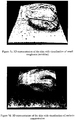
- Figure 7a shows 3D representation of real measured topography of a facial skin surface showing a human eye, according to the present invention.
- the shape is visualised by the use of a virtual lighting and shadows caused by its directionality.
- An alternative representation, with a false color mapping of z elevation for each x, y coordinate, is shown in fig. 7b .
- virtual lighting is still used to express small variations of the surface shape.
- This source can be either one used for the acquisition of the surface shape or it could be a different one having different wavelength. Using various sources with different wavelengths allows acquisition of extensive spectral reflectance data. Knowing the shape of the surface the influence on the illumination direction can be removed and true optical properties can be evaluated. This represents a significant advantage over images obtained in conventional ways and such images are much more suitable for quantitative and comparative evaluations due to their independence on the lighting conditions.
- spectral data can be used to synthesize normal colour appearance of the surface, as illustrated in Fig. 7c , the independence on lighting conditions can be used for additional analysis of the properties of the imaged object. Additionally, it will be appreciated that richer spectral data can be acquired, as opposite to the three channels Red, Green and Blue (RGB) used for standard colour imaging, which allows a better characterisation of the object.
- RGB Red, Green and Blue
- light is scattered on the surface boundary.
- light can propagate to a certain depth below the surface before it is scattered back.
- This propagation is characterised by an average value, called depth of propagation, which usually strongly depends on the light wavelength.
- depth of propagation usually strongly depends on the light wavelength.
- light of greater wavelength propagates deeper below the surface.
- This realization allows the invention to investigate the distribution of various constituents of biological tissue below the surface boundary.
- light sources of several different wavelength are used.
- the light sources can span the electromagnetic spectrum from the infrared to the ultraviolet end.
- the present invention makes use of a plurality of Luxeon K2 LED emitters with dominant wavelengths of 455, 470, 505, 530, 590, 617 and 627 nm. It will be appreciated that light sources outside the visible range can also be used to obtain additional information about the sample properties. Since the penetration depth increases as a function of the wavelength, ultraviolet or blue light is more suited to obtain information on the outermost layer of the tissue, while radiation closer to the infrared end of the spectrum will carry information about deeper layers of skin tissue. Multi-spectral imaging of various constituents of skin tissue below the surface can be achieved by using a number of light sources that span the electromagnetic spectrum in the desired range.
- the reflectance spectra measured by the present invention can be correlated to the absorption spectra of skin constituents.
- the measured values of melanin and haemoglobin, the two main chromophores of human skin can be compared to the theoretical values obtained using an optical model of skin reflection.
- various models of the reflection can be used to analyse the acquired data.
- the measured reflectance data model has to take into account the directionality and the particular spectrum of the light used.
- the exact placement of the illumination sources and the shape of the imaged skin surface are known makes it possible to recalculate the reflection coefficients under homogeneous illumination for each wavelength and for each pixel.
- the specular component of reflected light it is possible to use the Lambertian reflection model and the same equations, as described above, for calculating accurate reflection coefficients.
- the elimination of specular reflection suppresses the effect of undesired specular reflection from the stratuum corneum.
- Isotropic light propagation in the epidermis and dermis permits the use of the relatively simple Kubelka-Munk light propagation model, see for example P. Kubelka: New contributions to the optics of intensely light materials; J. Opt. Soc. Am. 44(1954), pp. 330-335 , and allows the invention to correlate the measured data with the concentration of melanin and haemoglobin, see for example T. J Farrell, M. S Patterson, B. Wilson: A diffusion theory of spatially resolved, steady-state diffuse reflectance for the non-invasive determination of tissue optical properties in vivo; Med. Phys. 19 (4), pp. 879-888 .
- the concentration and distribution of skin constituents has important implications in the assessment of skin health and the diagnosis of a number of conditions in the context of the present invention. For instance, hyper pigmentation caused by prolonged sun exposure can be easily identified and an inhomogeneous distribution of melanin on a particular area can be interpreted as a precursor of skin cancer.
- the invention provides a diagnosis method and device to detect indicators that a patient is prone to skin cancer.
- the ability to measure the distribution of haemoglobin, the main chromophore of human blood, can be used to examine a number of vascular lesions, e.g. rosacea, acne and telengiactesia.
- vascular lesions e.g. rosacea, acne and telengiactesia.
- the measurement of the vascularisation of the wound can help the physicians in identifying the most appropriate treatments and to shorten the healing time.
- the invention provides a diagnosis method and device to detect indicators to determine the status of a patients wound.
- Figures 7d and 7e show the distributions of melanin and hemoglobin based on in-vivo spectral measurements acquired by the device of the present invention.
- the apparatus can comprise either a zooming system with a single lens that has variable focal length or a lens-exchange system with a set of lenses of fixed focal length.
- the latter system is less costly and is the one used in one of the preferred embodiments described above.
- the imaging system can be equipped with a removable attachment. Because each lens has a different working distance, each lens will be integrated in a different removable attachment.
- the apparatus of the present invention can be equipped with an attachment-recognition system.
- the pattern itself can be either in the form of a bar-code strip reader, for example a bar-code commonly used for recognition of consumer goods and products, and shown as element (34) in Figure 5 .
- a color-encoded or other pattern can be used which can be easily processed by the imaging system. Because the intensities and spatial positions of the illumination sources will be different depending on what attachment is used, the use of different calibration data (described in previous part of the specification) will be required.
- the embodiments in the invention described with reference to the drawings comprise a computer apparatus and/or processes can be performed in a computer apparatus.
- the invention also extends to computer programs, particularly computer programs stored on or in a carrier adapted to bring the invention into practice.
- the program may be in the form of source code, object code, or a code intermediate source and object code, such as in partially compiled form or in any other form suitable for use in the implementation of the method according to the invention.
- the carrier may comprise a storage medium such as ROM, e.g. CD ROM, or magnetic recording medium, e.g. a floppy disk or hard disk.
- the carrier may be an electrical or optical signal which may be transmitted via an electrical or an optical cable or by radio or other means.
Landscapes
- Health & Medical Sciences (AREA)
- Life Sciences & Earth Sciences (AREA)
- Engineering & Computer Science (AREA)
- Physics & Mathematics (AREA)
- Medical Informatics (AREA)
- General Health & Medical Sciences (AREA)
- Surgery (AREA)
- Biophysics (AREA)
- Biomedical Technology (AREA)
- Molecular Biology (AREA)
- Heart & Thoracic Surgery (AREA)
- Animal Behavior & Ethology (AREA)
- Pathology (AREA)
- Public Health (AREA)
- Veterinary Medicine (AREA)
- Dermatology (AREA)
- Computer Vision & Pattern Recognition (AREA)
- Theoretical Computer Science (AREA)
- General Physics & Mathematics (AREA)
- Signal Processing (AREA)
- Artificial Intelligence (AREA)
- Data Mining & Analysis (AREA)
- Psychiatry (AREA)
- Spectroscopy & Molecular Physics (AREA)
- Quality & Reliability (AREA)
- Radiology & Medical Imaging (AREA)
- Physiology (AREA)
- Nuclear Medicine, Radiotherapy & Molecular Imaging (AREA)
- Optics & Photonics (AREA)
- General Engineering & Computer Science (AREA)
- Bioinformatics & Cheminformatics (AREA)
- Bioinformatics & Computational Biology (AREA)
- Evolutionary Biology (AREA)
- Evolutionary Computation (AREA)
- Investigating Or Analysing Materials By Optical Means (AREA)
- Measurement Of The Respiration, Hearing Ability, Form, And Blood Characteristics Of Living Organisms (AREA)
Claims (13)
- Dispositif de capture d'image destiné à l'acquisition de la topographie d'une surface de tissu de peau, comprenant :au moins trois sources d'éclairage (12a, 12b, 12c, 43) conçues pour éclairer ladite surface ;un système d'imagerie optique (10, 11, 41, 42) comprenant un unique capteur d'image (10, 41) et conçu pour la capture d'une pluralité d'images de ladite surface ;un moyen conçu pour commander lesdites sources d'éclairage (12a, 12b, 12c, 43) et ledit système optique (10, 11, 41, 42) permettant un changement des directions d'éclairage et une capture de ladite pluralité d'images présentant des propriétés spatiales différentes ; caractérisé en ce quele dispositif de capture d'image comprend en outre au moins deux polariseurs, un premier polariseur (13a, 13b, 13c, 45) placé entre les sources d'éclairage (12a, 12b, 12c, 43) et la surface, et un second polariseur (14, 44) entre la surface et le système d'imagerie optique (10, 11, 41, 42) destiné à éliminer la réflexion spéculaire, la lumière réfléchie de manière spéculaire depuis la surface du tissu ne changeant pas son état de polarisation et la lumière qui subit une réflexion diffuse changeant son état de polarisation ; etun moyen conçu pour analyser les différences entre des images capturées présentant différentes propriétés d'éclairage pour reconstruire la topographie de ladite surface sur la base d'un modèle de réflexion diffuse afin de produire une image en trois dimensions de ladite surface de tissu de peau, ledit moyen conçu pour analyser les différences entre des images comprenant en outre un moyen de mémorisation approprié pour mémoriser des propriétés d'éclairage, les propriétés d'éclairage étant mesurées individuellement pour chaque position et chaque source d'éclairage, le moyen de mémorisation étant en outre approprié pour mémoriser des données d'étalonnage destinées à l'étalonnage des intensités des sources d'éclairage à l'aide d'une surface de référence de forme et de propriétés optiques connues, et ces données d'étalonnage sont utilisées lors des mesures subséquentes pour compenser les variations des intensités d'éclairage.
- Dispositif de capture d'image selon la revendication 1, le premier et le second polariseur étant des polariseurs de lumière linéaires et étant alignés selon une relation de polarisation croisée l'un par rapport à l'autre.
- Dispositif de capture d'image selon la revendication 2, la pluralité d'images capturées correspondant sensiblement à la même surface avec des conditions d'éclairage variables toutes sous la même direction de polarisation de la lumière incidente et une direction de polarisation sensiblement croisée de la lumière réfléchie et diffusée détectée.
- Dispositif de capture d'image selon l'une quelconque des revendications précédentes, au moins deux sources d'éclairage étant éclairées simultanément durant l'acquisition d'une unique image et une combinaison linéaire de vecteurs d'éclairage représentatifs est utilisée en tant que source virtuelle, lesdites au moins deux sources éclairant la surface à un moment pour augmenter l'intensité d'éclairage et réduire le nombre d'images individuelles acquises pour produire ladite image en trois dimensions.
- Dispositif de capture d'image selon l'une quelconque des revendications précédentes, le moyen d'analyse comprenant un traitement de ladite pluralité d'images capturées pour calculer l'inclinaison de la surface au niveau de chaque point de la surface à partir de la différence entre les images prises sous des conditions d'éclairage différentes et récupérer la topographie de la surface.
- Dispositif de capture d'image selon l'une quelconque des revendications précédentes, au moins l'une des sources d'éclairage fonctionnant dans la plage de lumière visible du spectre électromagnétique.
- Dispositif de capture d'image selon l'une quelconque des revendications précédentes, au moins l'une des sources d'éclairage émettant un rayonnement en dehors de la plage de lumière visible du spectre électromagnétique.
- Dispositif de capture d'image selon l'une quelconque des revendications précédentes, les sources d'éclairage contenant des éléments destiné à un conditionnement supplémentaire de la lumière utilisant des optiques de réfraction ou de réflexion ou de dispersion telles que des lentilles, des diviseurs de faisceau, des miroirs plans ou courbes, des filtres, des diffuseurs réflectifs ou transmissifs.
- Dispositif de capture d'image selon l'une quelconque des revendications précédentes comprenant un système de lentilles d'imagerie interchangeable, le système de lentilles d'imagerie interchangeable étant intégré à un dispositif de fixation qui permet de maintenir la distance de travail optimale entre le système d'imagerie et l'objet inspecté.
- Dispositif de capture d'image selon l'une quelconque des revendications précédentes, le système optique comprenant au moins un tapis réfléchissant destiné à mesurer la variation des intensités des sources d'éclairage à des fins d'étalonnage supplémentaires.
- Dispositif de capture d'image selon l'une quelconque des revendications précédentes, lesdites sources d'éclairage présentant des caractéristiques spectrales non identiques destinées à mesurer les caractéristiques spectrales de la surface, les caractéristiques spectrales étant mesurées à l'aide de sources de lumière de longueurs d'onde différentes se propageant à des profondeurs différentes sous la surface et les différences spectrales étant utilisées pour la caractérisation subsurfacique de la surface.
- Dispositif de capture d'image selon l'une quelconque des revendications précédentes, l'image de surface capturée étant un tissu de peau humaine, les données collectées étant utilisées pour la caractérisation de la peau humaine et l'évaluation de l'état et la santé de la peau.
- Procédé de capture d'image destinée à l'acquisition de la topographie d'une surface de tissu de peau, comprenant les étapes consistant à :éclairer ladite surface à l'aide d'au moins trois sources d'éclairage (12a, 12b, 12c, 43) ;capturer une pluralité d'images de ladite surface éclairée à l'aide d'un système optique (10, 11, 41, 42) comprenant un unique capteur d'image (10, 41) ;commander lesdites sources d'éclairage et ledit système optique permettant de changer les propriétés spatiales de l'éclairage et de capturer ladite pluralité d'images avec différentes directions d'éclairage ; caractérisé en ce qu'il comprend les étapes consistant à :supprimer la réflexion spéculaire desdites images capturées à l'aide d'au moins deux polariseurs, un premier polariseur (13a, 13b, 13c, 45) étant placé entre les sources d'éclairage (12a, 12b, 12c, 43) et la surface, et un second polariseur (14, 44) entre la surface et le système d'imagerie optique (10, 11, 41, 42), une lumière réfléchie de manière spéculaire depuis la surface du tissu ne changeant pas son état de polarisation et une lumière qui subit une réflexion diffuse changeant son état de polarisation ; etanalyser les différences entre des images capturées avec des propriétés d'éclairage différentes pour reconstruire la topographie de ladite surface sur la base d'un modèle de réflexion diffuse, les propriétés d'éclairage étant mesurées individuellement pour chaque position et chaque source d'éclairage et mémorisées pour un traitement ultérieur des données, les intensités des sources d'éclairage étant étalonnées à l'aide d'une surface de référence de forme et de propriétés optiques connues, et ces données d'étalonnage étant utilisées lors des mesures subséquentes pour compenser les variations des intensités d'éclairage.
Priority Applications (1)
| Application Number | Priority Date | Filing Date | Title |
|---|---|---|---|
| EP10711832.5A EP2400890B1 (fr) | 2009-02-25 | 2010-02-25 | Procédé et appareil d'imagerie de tomographie de tissus |
Applications Claiming Priority (4)
| Application Number | Priority Date | Filing Date | Title |
|---|---|---|---|
| US15544209P | 2009-02-25 | 2009-02-25 | |
| EP09153655A EP2223650A1 (fr) | 2009-02-25 | 2009-02-25 | Procédé et appareil d'imagerie de tomographie de tissus |
| EP10711832.5A EP2400890B1 (fr) | 2009-02-25 | 2010-02-25 | Procédé et appareil d'imagerie de tomographie de tissus |
| PCT/EP2010/001168 WO2010097218A1 (fr) | 2009-02-25 | 2010-02-25 | Procédé et appareil d'imagerie de la topographie tissulaire |
Publications (2)
| Publication Number | Publication Date |
|---|---|
| EP2400890A1 EP2400890A1 (fr) | 2012-01-04 |
| EP2400890B1 true EP2400890B1 (fr) | 2018-10-24 |
Family
ID=40846117
Family Applications (2)
| Application Number | Title | Priority Date | Filing Date |
|---|---|---|---|
| EP09153655A Withdrawn EP2223650A1 (fr) | 2009-02-25 | 2009-02-25 | Procédé et appareil d'imagerie de tomographie de tissus |
| EP10711832.5A Active EP2400890B1 (fr) | 2009-02-25 | 2010-02-25 | Procédé et appareil d'imagerie de tomographie de tissus |
Family Applications Before (1)
| Application Number | Title | Priority Date | Filing Date |
|---|---|---|---|
| EP09153655A Withdrawn EP2223650A1 (fr) | 2009-02-25 | 2009-02-25 | Procédé et appareil d'imagerie de tomographie de tissus |
Country Status (4)
| Country | Link |
|---|---|
| US (2) | US20110304705A1 (fr) |
| EP (2) | EP2223650A1 (fr) |
| IE (1) | IES20100104A2 (fr) |
| WO (1) | WO2010097218A1 (fr) |
Families Citing this family (68)
| Publication number | Priority date | Publication date | Assignee | Title |
|---|---|---|---|---|
| US8886206B2 (en) | 2009-05-01 | 2014-11-11 | Digimarc Corporation | Methods and systems for content processing |
| US9749607B2 (en) | 2009-07-16 | 2017-08-29 | Digimarc Corporation | Coordinated illumination and image signal capture for enhanced signal detection |
| US20120056994A1 (en) * | 2010-08-30 | 2012-03-08 | University Of Southern California | Single-shot photometric stereo by spectral multiplexing |
| DK2668665T3 (da) | 2011-01-27 | 2019-10-07 | Wabtec Control Systems Pty Ltd | Kameraenhed til ekstrahering af billeddybdediskontinuitet og fremgangsmåde |
| FR2972109A1 (fr) * | 2011-03-04 | 2012-09-07 | Peritesco | Procede de determination d'un eclairage standardise pour l'etude de l'etat de surface d'une zone de peau et dispositif associe |
| ITFI20110045A1 (it) * | 2011-03-26 | 2012-09-27 | Menci Software S R L | Apparato e metodo per la rilevazione e la ricostruzione di immagini in tre dimensioni. |
| US9001326B2 (en) | 2011-12-13 | 2015-04-07 | Welch Allyn, Inc. | Method and apparatus for observing subsurfaces of a target material |
| CN104205159B (zh) | 2012-01-06 | 2018-02-02 | 凯米拉公司 | 表征起皱材料的方法 |
| MY182748A (en) * | 2012-02-09 | 2021-02-05 | Institute Of Tech Petronas Sdn Bhd | Methodology and apparatus for objective and in vivo assessment of granulation tissue growth in chronic ulcers using digital imaging |
| US9060113B2 (en) | 2012-05-21 | 2015-06-16 | Digimarc Corporation | Sensor-synchronized spectrally-structured-light imaging |
| US9593982B2 (en) | 2012-05-21 | 2017-03-14 | Digimarc Corporation | Sensor-synchronized spectrally-structured-light imaging |
| WO2014047712A1 (fr) * | 2012-09-26 | 2014-04-03 | Windsor Clinical Research Inc. | Dispositif d'imagerie de topographie faciale avec photographie flash à sources lumineuses multiples et procédé pour les mélanger |
| CN102944928B (zh) * | 2012-10-15 | 2015-07-29 | 中国科学院深圳先进技术研究院 | 一种三维内窥镜及其三维重建方法 |
| US9857470B2 (en) * | 2012-12-28 | 2018-01-02 | Microsoft Technology Licensing, Llc | Using photometric stereo for 3D environment modeling |
| US9940553B2 (en) | 2013-02-22 | 2018-04-10 | Microsoft Technology Licensing, Llc | Camera/object pose from predicted coordinates |
| US10617305B2 (en) | 2013-02-28 | 2020-04-14 | Canfield Scientific, Incorporated | Dermatoscope devices |
| WO2014160510A2 (fr) * | 2013-03-13 | 2014-10-02 | Massachusetts Institute Of Technology | Stéréo-endoscopie photométrique |
| US9566414B2 (en) | 2013-03-13 | 2017-02-14 | Hansen Medical, Inc. | Integrated catheter and guide wire controller |
| US9101320B2 (en) * | 2013-04-09 | 2015-08-11 | Elc Management Llc | Skin diagnostic and image processing methods |
| US9256963B2 (en) | 2013-04-09 | 2016-02-09 | Elc Management Llc | Skin diagnostic and image processing systems, apparatus and articles |
| US20140378810A1 (en) | 2013-04-18 | 2014-12-25 | Digimarc Corporation | Physiologic data acquisition and analysis |
| FR3005255A1 (fr) * | 2013-05-06 | 2014-11-07 | Johnson & Johnson Consumer Holdings France | Procede d'evaluation de caractere erythemal d'une zone irradiee de la peau |
| US9621760B2 (en) | 2013-06-07 | 2017-04-11 | Digimarc Corporation | Information coding and decoding in spectral differences |
| NL2010944C2 (en) * | 2013-06-10 | 2014-12-15 | Symae Technologies Holding B V | Device and method for analysing the optical characteristics of skin and hair. |
| US9458990B2 (en) | 2013-08-01 | 2016-10-04 | 3Gen, Inc. | Dermoscopy illumination device with selective polarization and orange light for enhanced viewing of pigmented tissue |
| KR20150094196A (ko) * | 2014-02-11 | 2015-08-19 | 서울바이오시스 주식회사 | 피부 상태 진단 장치 및 이를 이용하는 피부 상태 진단 방법 |
| CN111643054A (zh) * | 2014-02-27 | 2020-09-11 | 直观外科手术操作公司 | 用于镜面反射检测和减少的系统和方法 |
| US9582890B2 (en) * | 2014-05-19 | 2017-02-28 | Ricoh Company, Ltd. | Superpixel-based image segmentation using shading and albedo decomposition |
| JP6424020B2 (ja) | 2014-06-09 | 2018-11-14 | 株式会社キーエンス | 画像検査装置、画像検査方法、画像検査プログラム及びコンピュータで読み取り可能な記録媒体並びに記録した機器 |
| US10113910B2 (en) | 2014-08-26 | 2018-10-30 | Digimarc Corporation | Sensor-synchronized spectrally-structured-light imaging |
| US10004403B2 (en) * | 2014-08-28 | 2018-06-26 | Mela Sciences, Inc. | Three dimensional tissue imaging system and method |
| JP6406606B2 (ja) * | 2014-10-06 | 2018-10-17 | パナソニックIpマネジメント株式会社 | 光沢判定装置および光沢判定方法 |
| US9727941B1 (en) | 2014-11-19 | 2017-08-08 | Digimarc Corporation | Optimizing optical scanners for digital watermark detection |
| EP3057067B1 (fr) * | 2015-02-16 | 2017-08-23 | Thomson Licensing | Dispositif et procédé pour estimer une partie brillante de rayonnement |
| JP6576059B2 (ja) * | 2015-03-10 | 2019-09-18 | キヤノン株式会社 | 情報処理、情報処理方法、プログラム |
| DE112016001559T5 (de) * | 2015-03-31 | 2018-01-04 | Sony Corporation | Abbildungssystem, das strukturiertes Licht zur Tiefenrückgewinnung nutzt |
| US10893814B2 (en) | 2015-10-06 | 2021-01-19 | Koninklijke Philips N.V. | System and method for obtaining vital sign related information of a living being |
| ITUB20159560A1 (it) | 2015-12-23 | 2017-06-23 | Torino Politecnico | Dispositivo e procedimento di acquisizione di immagini mediche per l?analisi di ulcere |
| WO2017117320A1 (fr) * | 2015-12-30 | 2017-07-06 | Empire Technology Development Llc | Appareil d'analyse de surface irrégulière au moyen de l'énergie électromagnétique |
| KR101799184B1 (ko) * | 2016-03-07 | 2017-11-20 | 재단법인대구경북과학기술원 | 피부 다중 분광 이미징을 위한 모바일 기기 부착형 조명 장치 |
| AU2017247617A1 (en) * | 2016-04-06 | 2018-10-25 | University Of The West Of England, Bristol | Non-contact apparatus and method for capturing skin surface image data |
| GB2540001B (en) * | 2016-04-22 | 2017-07-19 | Score Group Plc | An imaging system and method |
| US10255674B2 (en) | 2016-05-25 | 2019-04-09 | International Business Machines Corporation | Surface reflectance reduction in images using non-specular portion replacement |
| GB2557928A (en) * | 2016-12-16 | 2018-07-04 | Fuel 3D Tech Limited | Systems and methods for obtaining data characterizing a three-dimensional object |
| DE102017200356A1 (de) * | 2017-01-11 | 2018-07-12 | Robert Bosch Gmbh | Verfahren zur Analyse eines Messbereichs und Miniaturspektrometer |
| US20180289291A1 (en) * | 2017-04-07 | 2018-10-11 | Bunnie Richie | Health diagnostic fingerprint scanner |
| KR102049040B1 (ko) * | 2017-08-07 | 2019-11-27 | (재)예수병원유지재단 | 생체용 거칠기 진단장치 |
| EP3460753A1 (fr) * | 2017-09-21 | 2019-03-27 | Infaimon, SL | Système stéréo photométrique et procédé d'inspection d'objets à l'aide d'une caméra à une prise et programme informatique |
| EP3479756A1 (fr) * | 2017-11-02 | 2019-05-08 | Koninklijke Philips N.V. | Capteur optique pour évaluer des propriétés de la peau et methode associée |
| WO2019092599A1 (fr) * | 2017-11-09 | 2019-05-16 | Silvia Colagrande | Scanner d'image à éclairage multidirectionnel |
| US10706524B2 (en) * | 2017-11-28 | 2020-07-07 | Henkel IP & Holding GmbH | Systems and methods for analyzing stained fabric articles |
| US10441379B2 (en) | 2017-12-28 | 2019-10-15 | 3Gen, Inc. | Multipurpose medical illuminator with magnification |
| EP3505048A1 (fr) * | 2017-12-28 | 2019-07-03 | Koninklijke Philips N.V. | Capteur optique de peau utilisant des bandes spectrales optimales pour minimiser l'effet de la pression sur le capteur |
| US10702160B2 (en) * | 2018-05-02 | 2020-07-07 | Canfield Scientific, Incorporated | Skin assessment using image fusion |
| US10757393B2 (en) * | 2018-05-06 | 2020-08-25 | American Advanced Technology, Llc | Method and apparatus for measuring characteristics of a surface topology |
| US11193090B2 (en) | 2018-05-16 | 2021-12-07 | Henkel IP & Holding GmbH | Systems and methods of forming and analyzing dissolvable articles |
| US20190362510A1 (en) * | 2018-05-24 | 2019-11-28 | Lu Sun | Method and system for evaluating friction coefficient and skid resistence of a surface |
| KR101971867B1 (ko) * | 2018-06-18 | 2019-04-24 | 주식회사 인시스 | 피부의 색소침착 측정방법 |
| US10789702B2 (en) | 2018-06-25 | 2020-09-29 | Henkel IP & Holding GmbH | Systems and methods for analyzing a fabric article |
| CN113614487A (zh) * | 2019-03-26 | 2021-11-05 | 索尼集团公司 | 图像处理装置、图像处理方法和图像处理程序 |
| US11348334B1 (en) * | 2019-06-30 | 2022-05-31 | George Douglas MacEwen | Methods and systems for skin color matching using an imaging device and a controlled light source |
| CN110580686B (zh) * | 2019-08-02 | 2023-01-20 | 天津大学 | 在散射环境中基于双目视觉的偏振图像复原装置及方法 |
| US11395714B2 (en) | 2019-11-11 | 2022-07-26 | Dermlite Llc | Medical illuminator with variable polarization |
| US11636591B2 (en) | 2020-06-18 | 2023-04-25 | Alibaba Group Holding Limited | Surface imaging using high incident angle of light rays |
| CN112747822A (zh) * | 2020-07-17 | 2021-05-04 | 奕目(上海)科技有限公司 | 一种三维成像系统和方法 |
| US20220202325A1 (en) * | 2020-12-31 | 2022-06-30 | Bioxytech Retina, Inc. | Methods and devices for measuring structural and functional properties of tissue |
| GB2607341A (en) * | 2021-06-04 | 2022-12-07 | Dyson Technology Ltd | Skincare device |
| US20230419523A1 (en) * | 2022-06-28 | 2023-12-28 | Zebra Technologies Corporation | Method, System and Apparatus for Photometric Stereo Reconstruction of a Surface |
Family Cites Families (32)
| Publication number | Priority date | Publication date | Assignee | Title |
|---|---|---|---|---|
| US5016173A (en) * | 1989-04-13 | 1991-05-14 | Vanguard Imaging Ltd. | Apparatus and method for monitoring visually accessible surfaces of the body |
| FR2665959B1 (fr) * | 1990-08-16 | 1994-01-14 | Oreal | Appareil destine a permettre d'evaluer la brillance d'une surface, en particulier de la peau. |
| AT403654B (de) * | 1994-12-01 | 1998-04-27 | Binder Michael Dr | Einrichtung zur optischen untersuchung von human-haut sowie derselben zugeordnete auswertungs-einrichtung |
| US6263233B1 (en) | 1995-07-13 | 2001-07-17 | Lucid, Inc. | Handheld imaging microscope |
| US20020042559A1 (en) * | 1995-08-22 | 2002-04-11 | Buschmann Johannes P. | Method for validating and/or calibrating devices used for carrying out photometry of living tissues and a deivice for implementing said method |
| US6586193B2 (en) * | 1996-04-25 | 2003-07-01 | Genicon Sciences Corporation | Analyte assay using particulate labels |
| DE19725633C1 (de) | 1997-06-17 | 1998-12-17 | Zentrum Fuer Neuroinformatik G | Verfahren und Anordnung zur Analyse der Beschaffenheit einer Oberfläche |
| JP4053653B2 (ja) | 1998-04-21 | 2008-02-27 | 株式会社モリテックス | Ccdマイクロスコープ |
| DE59812335D1 (de) | 1998-09-30 | 2005-01-05 | Courage Brewing Ltd | Vorrichtung zur messtechnischen Erfassung von Parametern der Haut |
| US6571003B1 (en) | 1999-06-14 | 2003-05-27 | The Procter & Gamble Company | Skin imaging and analysis systems and methods |
| US7904139B2 (en) * | 1999-08-26 | 2011-03-08 | Non-Invasive Technology Inc. | Optical examination of biological tissue using non-contact irradiation and detection |
| US6686921B1 (en) * | 2000-08-01 | 2004-02-03 | International Business Machines Corporation | Method and apparatus for acquiring a set of consistent image maps to represent the color of the surface of an object |
| FR2821152B3 (fr) * | 2001-02-22 | 2003-03-14 | Hertsel Adhoute | Dispositif photographique de mesure sans contact et de representation 3d du micro relief cutane |
| FR2825466B1 (fr) * | 2001-06-05 | 2003-10-17 | Essilor Int | Dispositif de detection automatique de caracteristiques d'un verre ophtalmique et dispositif de positionnement automatique d'un pion de centrage et d'entrainement comprenant un tel dispositif de detection |
| JP3660611B2 (ja) | 2001-07-12 | 2005-06-15 | 株式会社モリテックス | 撮像装置とそれに使用する撮像ヘッド |
| US6907193B2 (en) | 2001-11-08 | 2005-06-14 | Johnson & Johnson Consumer Companies, Inc. | Method of taking polarized images of the skin and the use thereof |
| US7006223B2 (en) | 2003-03-07 | 2006-02-28 | 3Gen, Llc. | Dermoscopy epiluminescence device employing cross and parallel polarization |
| US7539330B2 (en) * | 2004-06-01 | 2009-05-26 | Lumidigm, Inc. | Multispectral liveness determination |
| US7920908B2 (en) * | 2003-10-16 | 2011-04-05 | David Hattery | Multispectral imaging for quantitative contrast of functional and structural features of layers inside optically dense media such as tissue |
| US8026942B2 (en) * | 2004-10-29 | 2011-09-27 | Johnson & Johnson Consumer Companies, Inc. | Skin imaging system with probe |
| US8548570B2 (en) * | 2004-11-29 | 2013-10-01 | Hypermed Imaging, Inc. | Hyperspectral imaging of angiogenesis |
| CA2597254A1 (fr) * | 2005-02-09 | 2006-08-17 | Inlight Solutions, Inc. | Procedes et appareil de determinations non invasives d'analytes |
| US20110184260A1 (en) * | 2005-02-09 | 2011-07-28 | Robinson M Ries | Methods and Apparatuses for Noninvasive Determinations of Analytes |
| US9597024B2 (en) * | 2005-02-09 | 2017-03-21 | Medici Instruments Llc | Methods and apparatuses for noninvasive determinations of analytes |
| US20060239547A1 (en) * | 2005-04-20 | 2006-10-26 | Robinson M R | Use of optical skin measurements to determine cosmetic skin properties |
| US20070080223A1 (en) * | 2005-10-07 | 2007-04-12 | Sherwood Services Ag | Remote monitoring of medical device |
| US7639862B2 (en) * | 2005-12-09 | 2009-12-29 | E.I. Du Pont De Nemours And Company | Method and apparatus for quantifying pigment dispersion quality by paint drawdown |
| US7878652B2 (en) * | 2006-01-24 | 2011-02-01 | University Of Tennessee Research Foundation | Adaptive photoscreening system |
| JP2007206797A (ja) * | 2006-01-31 | 2007-08-16 | Omron Corp | 画像処理方法および画像処理装置 |
| US20120321759A1 (en) * | 2007-01-05 | 2012-12-20 | Myskin, Inc. | Characterization of food materials by optomagnetic fingerprinting |
| US20090245603A1 (en) * | 2007-01-05 | 2009-10-01 | Djuro Koruga | System and method for analysis of light-matter interaction based on spectral convolution |
| DE102007018048A1 (de) * | 2007-04-13 | 2008-10-16 | Michael Schwertner | Verfahren und Anordnung zur optischen Abbildung mit Tiefendiskriminierung |
-
2009
- 2009-02-25 EP EP09153655A patent/EP2223650A1/fr not_active Withdrawn
-
2010
- 2010-02-25 WO PCT/EP2010/001168 patent/WO2010097218A1/fr active Application Filing
- 2010-02-25 EP EP10711832.5A patent/EP2400890B1/fr active Active
- 2010-02-25 US US13/203,005 patent/US20110304705A1/en not_active Abandoned
- 2010-02-25 IE IE20100104A patent/IES20100104A2/en not_active IP Right Cessation
-
2016
- 2016-03-23 US US15/078,714 patent/US9706929B2/en active Active
Non-Patent Citations (1)
| Title |
|---|
| None * |
Also Published As
| Publication number | Publication date |
|---|---|
| EP2400890A1 (fr) | 2012-01-04 |
| EP2223650A1 (fr) | 2010-09-01 |
| US20110304705A1 (en) | 2011-12-15 |
| IES20100104A2 (en) | 2010-09-29 |
| WO2010097218A1 (fr) | 2010-09-02 |
| US20160270665A1 (en) | 2016-09-22 |
| US9706929B2 (en) | 2017-07-18 |
Similar Documents
| Publication | Publication Date | Title |
|---|---|---|
| US9706929B2 (en) | Method and apparatus for imaging tissue topography | |
| US11653874B2 (en) | Method and system for characterizing tissue in three dimensions using multimode optical measurements | |
| US9277866B2 (en) | Method and apparatus for analysis of turbid media via single-element detection using structured illumination | |
| JP5580809B2 (ja) | 組織の形態学的パラメータと生理学的特性を決定する光学的方法 | |
| CN103477205B (zh) | 光学偏振成像 | |
| AU2014212124A1 (en) | Method and system for characterizing tissue in three dimensions using multimode optical measurements | |
| RU2657377C2 (ru) | Интеллектуальная насадка на смартфон для определения чистоты, влажности и фотовозраста кожи | |
| KR20150087258A (ko) | 효율적인 변조 이미지 진단 | |
| EP2050385B1 (fr) | Procédé et appareil pour la mesure de l'épaisseur du collagène | |
| CA2594010A1 (fr) | Procedes et appareil de mesure de la rugosite d'une surface | |
| CA2718972A1 (fr) | Imageur a spectres multiples miniaturise pour une mesure en temps reel de l'oxygenation d'un tissu | |
| Kainerstorfer et al. | Principal component model of multispectral data for near real-time skin chromophore mapping | |
| WO2019014168A1 (fr) | Scanner en lumière ifp et visible pour des images de tissus co-enregistrées | |
| Kainerstorfer et al. | Quantitative principal component model for skin chromophore mapping using multi-spectral images and spatial priors | |
| EP1931262A2 (fr) | Repere d'etalonnage a usage unique pour imagerie hyperspectrale | |
| JP2016540622A (ja) | 医用イメージング | |
| EP3351162A1 (fr) | Procédé mis en uvre par ordinateur, système et produits-programmes informatiques pour caractériser une lésion de la peau | |
| Paquit et al. | Simulation of skin reflectance images using 3D tissue modeling and multispectral Monte Carlo light propagation | |
| RU2528087C1 (ru) | Устройство для определения концентрации гемоглобина и степени оксигенации крови в слизистых оболочках | |
| Stephens et al. | Novel, Compelling, Noninvasive Techniques for Evaluating Cosmetic Products | |
| IES85695Y1 (en) | Method and apparatus for imaging tissue topography | |
| Meriaudeau et al. | 3D and multispectral imaging for subcutaneous veins detection | |
| IE20100104U1 (en) | Method and apparatus for imaging tissue topography | |
| MacKinnon et al. | Toward in vivo diagnosis of skin cancer using multimode imaging dermoscopy:(I) clinical system development and validation | |
| Rey-Barroso et al. | Polarized multispectral imaging for the diagnosis of skin cancer |
Legal Events
| Date | Code | Title | Description |
|---|---|---|---|
| PUAI | Public reference made under article 153(3) epc to a published international application that has entered the european phase |
Free format text: ORIGINAL CODE: 0009012 |
|
| 17P | Request for examination filed |
Effective date: 20110921 |
|
| AK | Designated contracting states |
Kind code of ref document: A1 Designated state(s): AT BE BG CH CY CZ DE DK EE ES FI FR GB GR HR HU IE IS IT LI LT LU LV MC MK MT NL NO PL PT RO SE SI SK SM TR |
|
| DAX | Request for extension of the european patent (deleted) | ||
| RAP1 | Party data changed (applicant data changed or rights of an application transferred) |
Owner name: THE PROVOST, FELLOWS, FOUNDATION SCHOLARS, & THE O |
|
| 17Q | First examination report despatched |
Effective date: 20151002 |
|
| STAA | Information on the status of an ep patent application or granted ep patent |
Free format text: STATUS: EXAMINATION IS IN PROGRESS |
|
| REG | Reference to a national code |
Ref country code: DE Ref legal event code: R079 Ref document number: 602010054563 Country of ref document: DE Free format text: PREVIOUS MAIN CLASS: A61B0005103000 Ipc: A61B0005000000 |
|
| GRAP | Despatch of communication of intention to grant a patent |
Free format text: ORIGINAL CODE: EPIDOSNIGR1 |
|
| STAA | Information on the status of an ep patent application or granted ep patent |
Free format text: STATUS: GRANT OF PATENT IS INTENDED |
|
| RIC1 | Information provided on ipc code assigned before grant |
Ipc: G06T 7/00 20170101ALI20180411BHEP Ipc: A61B 5/145 20060101ALI20180411BHEP Ipc: A61B 5/00 20060101AFI20180411BHEP Ipc: G06K 9/62 20060101ALI20180411BHEP Ipc: G06T 7/586 20170101ALI20180411BHEP |
|
| INTG | Intention to grant announced |
Effective date: 20180507 |
|
| GRAS | Grant fee paid |
Free format text: ORIGINAL CODE: EPIDOSNIGR3 |
|
| GRAA | (expected) grant |
Free format text: ORIGINAL CODE: 0009210 |
|
| STAA | Information on the status of an ep patent application or granted ep patent |
Free format text: STATUS: THE PATENT HAS BEEN GRANTED |
|
| AK | Designated contracting states |
Kind code of ref document: B1 Designated state(s): AT BE BG CH CY CZ DE DK EE ES FI FR GB GR HR HU IE IS IT LI LT LU LV MC MK MT NL NO PL PT RO SE SI SK SM TR |
|
| REG | Reference to a national code |
Ref country code: GB Ref legal event code: FG4D |
|
| REG | Reference to a national code |
Ref country code: CH Ref legal event code: EP |
|
| REG | Reference to a national code |
Ref country code: IE Ref legal event code: FG4D |
|
| REG | Reference to a national code |
Ref country code: DE Ref legal event code: R096 Ref document number: 602010054563 Country of ref document: DE Ref country code: AT Ref legal event code: REF Ref document number: 1055696 Country of ref document: AT Kind code of ref document: T Effective date: 20181115 |
|
| REG | Reference to a national code |
Ref country code: NL Ref legal event code: MP Effective date: 20181024 |
|
| REG | Reference to a national code |
Ref country code: LT Ref legal event code: MG4D |
|
| REG | Reference to a national code |
Ref country code: AT Ref legal event code: MK05 Ref document number: 1055696 Country of ref document: AT Kind code of ref document: T Effective date: 20181024 |
|
| PG25 | Lapsed in a contracting state [announced via postgrant information from national office to epo] |
Ref country code: NL Free format text: LAPSE BECAUSE OF FAILURE TO SUBMIT A TRANSLATION OF THE DESCRIPTION OR TO PAY THE FEE WITHIN THE PRESCRIBED TIME-LIMIT Effective date: 20181024 |
|
| PG25 | Lapsed in a contracting state [announced via postgrant information from national office to epo] |
Ref country code: PL Free format text: LAPSE BECAUSE OF FAILURE TO SUBMIT A TRANSLATION OF THE DESCRIPTION OR TO PAY THE FEE WITHIN THE PRESCRIBED TIME-LIMIT Effective date: 20181024 Ref country code: LT Free format text: LAPSE BECAUSE OF FAILURE TO SUBMIT A TRANSLATION OF THE DESCRIPTION OR TO PAY THE FEE WITHIN THE PRESCRIBED TIME-LIMIT Effective date: 20181024 Ref country code: ES Free format text: LAPSE BECAUSE OF FAILURE TO SUBMIT A TRANSLATION OF THE DESCRIPTION OR TO PAY THE FEE WITHIN THE PRESCRIBED TIME-LIMIT Effective date: 20181024 Ref country code: BG Free format text: LAPSE BECAUSE OF FAILURE TO SUBMIT A TRANSLATION OF THE DESCRIPTION OR TO PAY THE FEE WITHIN THE PRESCRIBED TIME-LIMIT Effective date: 20190124 Ref country code: LV Free format text: LAPSE BECAUSE OF FAILURE TO SUBMIT A TRANSLATION OF THE DESCRIPTION OR TO PAY THE FEE WITHIN THE PRESCRIBED TIME-LIMIT Effective date: 20181024 Ref country code: HR Free format text: LAPSE BECAUSE OF FAILURE TO SUBMIT A TRANSLATION OF THE DESCRIPTION OR TO PAY THE FEE WITHIN THE PRESCRIBED TIME-LIMIT Effective date: 20181024 Ref country code: FI Free format text: LAPSE BECAUSE OF FAILURE TO SUBMIT A TRANSLATION OF THE DESCRIPTION OR TO PAY THE FEE WITHIN THE PRESCRIBED TIME-LIMIT Effective date: 20181024 Ref country code: IS Free format text: LAPSE BECAUSE OF FAILURE TO SUBMIT A TRANSLATION OF THE DESCRIPTION OR TO PAY THE FEE WITHIN THE PRESCRIBED TIME-LIMIT Effective date: 20190224 Ref country code: NO Free format text: LAPSE BECAUSE OF FAILURE TO SUBMIT A TRANSLATION OF THE DESCRIPTION OR TO PAY THE FEE WITHIN THE PRESCRIBED TIME-LIMIT Effective date: 20190124 Ref country code: AT Free format text: LAPSE BECAUSE OF FAILURE TO SUBMIT A TRANSLATION OF THE DESCRIPTION OR TO PAY THE FEE WITHIN THE PRESCRIBED TIME-LIMIT Effective date: 20181024 |
|
| PG25 | Lapsed in a contracting state [announced via postgrant information from national office to epo] |
Ref country code: GR Free format text: LAPSE BECAUSE OF FAILURE TO SUBMIT A TRANSLATION OF THE DESCRIPTION OR TO PAY THE FEE WITHIN THE PRESCRIBED TIME-LIMIT Effective date: 20190125 Ref country code: PT Free format text: LAPSE BECAUSE OF FAILURE TO SUBMIT A TRANSLATION OF THE DESCRIPTION OR TO PAY THE FEE WITHIN THE PRESCRIBED TIME-LIMIT Effective date: 20190224 Ref country code: SE Free format text: LAPSE BECAUSE OF FAILURE TO SUBMIT A TRANSLATION OF THE DESCRIPTION OR TO PAY THE FEE WITHIN THE PRESCRIBED TIME-LIMIT Effective date: 20181024 |
|
| REG | Reference to a national code |
Ref country code: DE Ref legal event code: R097 Ref document number: 602010054563 Country of ref document: DE |
|
| PG25 | Lapsed in a contracting state [announced via postgrant information from national office to epo] |
Ref country code: DK Free format text: LAPSE BECAUSE OF FAILURE TO SUBMIT A TRANSLATION OF THE DESCRIPTION OR TO PAY THE FEE WITHIN THE PRESCRIBED TIME-LIMIT Effective date: 20181024 Ref country code: CZ Free format text: LAPSE BECAUSE OF FAILURE TO SUBMIT A TRANSLATION OF THE DESCRIPTION OR TO PAY THE FEE WITHIN THE PRESCRIBED TIME-LIMIT Effective date: 20181024 |
|
| PG25 | Lapsed in a contracting state [announced via postgrant information from national office to epo] |
Ref country code: SK Free format text: LAPSE BECAUSE OF FAILURE TO SUBMIT A TRANSLATION OF THE DESCRIPTION OR TO PAY THE FEE WITHIN THE PRESCRIBED TIME-LIMIT Effective date: 20181024 Ref country code: EE Free format text: LAPSE BECAUSE OF FAILURE TO SUBMIT A TRANSLATION OF THE DESCRIPTION OR TO PAY THE FEE WITHIN THE PRESCRIBED TIME-LIMIT Effective date: 20181024 Ref country code: SM Free format text: LAPSE BECAUSE OF FAILURE TO SUBMIT A TRANSLATION OF THE DESCRIPTION OR TO PAY THE FEE WITHIN THE PRESCRIBED TIME-LIMIT Effective date: 20181024 Ref country code: RO Free format text: LAPSE BECAUSE OF FAILURE TO SUBMIT A TRANSLATION OF THE DESCRIPTION OR TO PAY THE FEE WITHIN THE PRESCRIBED TIME-LIMIT Effective date: 20181024 |
|
| PLBE | No opposition filed within time limit |
Free format text: ORIGINAL CODE: 0009261 |
|
| STAA | Information on the status of an ep patent application or granted ep patent |
Free format text: STATUS: NO OPPOSITION FILED WITHIN TIME LIMIT |
|
| REG | Reference to a national code |
Ref country code: CH Ref legal event code: PL |
|
| 26N | No opposition filed |
Effective date: 20190725 |
|
| PG25 | Lapsed in a contracting state [announced via postgrant information from national office to epo] |
Ref country code: MC Free format text: LAPSE BECAUSE OF FAILURE TO SUBMIT A TRANSLATION OF THE DESCRIPTION OR TO PAY THE FEE WITHIN THE PRESCRIBED TIME-LIMIT Effective date: 20181024 Ref country code: LU Free format text: LAPSE BECAUSE OF NON-PAYMENT OF DUE FEES Effective date: 20190225 Ref country code: SI Free format text: LAPSE BECAUSE OF FAILURE TO SUBMIT A TRANSLATION OF THE DESCRIPTION OR TO PAY THE FEE WITHIN THE PRESCRIBED TIME-LIMIT Effective date: 20181024 |
|
| REG | Reference to a national code |
Ref country code: BE Ref legal event code: MM Effective date: 20190228 |
|
| REG | Reference to a national code |
Ref country code: IE Ref legal event code: MM4A |
|
| PG25 | Lapsed in a contracting state [announced via postgrant information from national office to epo] |
Ref country code: LI Free format text: LAPSE BECAUSE OF NON-PAYMENT OF DUE FEES Effective date: 20190228 Ref country code: CH Free format text: LAPSE BECAUSE OF NON-PAYMENT OF DUE FEES Effective date: 20190228 |
|
| PG25 | Lapsed in a contracting state [announced via postgrant information from national office to epo] |
Ref country code: IE Free format text: LAPSE BECAUSE OF NON-PAYMENT OF DUE FEES Effective date: 20190225 |
|
| PG25 | Lapsed in a contracting state [announced via postgrant information from national office to epo] |
Ref country code: BE Free format text: LAPSE BECAUSE OF NON-PAYMENT OF DUE FEES Effective date: 20190228 |
|
| PG25 | Lapsed in a contracting state [announced via postgrant information from national office to epo] |
Ref country code: TR Free format text: LAPSE BECAUSE OF FAILURE TO SUBMIT A TRANSLATION OF THE DESCRIPTION OR TO PAY THE FEE WITHIN THE PRESCRIBED TIME-LIMIT Effective date: 20181024 |
|
| PG25 | Lapsed in a contracting state [announced via postgrant information from national office to epo] |
Ref country code: MT Free format text: LAPSE BECAUSE OF NON-PAYMENT OF DUE FEES Effective date: 20190225 |
|
| PG25 | Lapsed in a contracting state [announced via postgrant information from national office to epo] |
Ref country code: CY Free format text: LAPSE BECAUSE OF FAILURE TO SUBMIT A TRANSLATION OF THE DESCRIPTION OR TO PAY THE FEE WITHIN THE PRESCRIBED TIME-LIMIT Effective date: 20181024 |
|
| PG25 | Lapsed in a contracting state [announced via postgrant information from national office to epo] |
Ref country code: HU Free format text: LAPSE BECAUSE OF FAILURE TO SUBMIT A TRANSLATION OF THE DESCRIPTION OR TO PAY THE FEE WITHIN THE PRESCRIBED TIME-LIMIT; INVALID AB INITIO Effective date: 20100225 |
|
| PG25 | Lapsed in a contracting state [announced via postgrant information from national office to epo] |
Ref country code: MK Free format text: LAPSE BECAUSE OF FAILURE TO SUBMIT A TRANSLATION OF THE DESCRIPTION OR TO PAY THE FEE WITHIN THE PRESCRIBED TIME-LIMIT Effective date: 20181024 |
|
| PGFP | Annual fee paid to national office [announced via postgrant information from national office to epo] |
Ref country code: FR Payment date: 20230220 Year of fee payment: 14 |
|
| PGFP | Annual fee paid to national office [announced via postgrant information from national office to epo] |
Ref country code: IT Payment date: 20230210 Year of fee payment: 14 Ref country code: GB Payment date: 20230209 Year of fee payment: 14 Ref country code: DE Payment date: 20230227 Year of fee payment: 14 |
|
| P01 | Opt-out of the competence of the unified patent court (upc) registered |
Effective date: 20230608 |