EP2400633A2 - Stromübertragungsvorrichtung, Stromempfangsvorrichtung und drahtloses Stromübertragungssystem - Google Patents
Stromübertragungsvorrichtung, Stromempfangsvorrichtung und drahtloses Stromübertragungssystem Download PDFInfo
- Publication number
- EP2400633A2 EP2400633A2 EP11170980A EP11170980A EP2400633A2 EP 2400633 A2 EP2400633 A2 EP 2400633A2 EP 11170980 A EP11170980 A EP 11170980A EP 11170980 A EP11170980 A EP 11170980A EP 2400633 A2 EP2400633 A2 EP 2400633A2
- Authority
- EP
- European Patent Office
- Prior art keywords
- receiving apparatus
- power receiving
- power
- electrode
- transmitting apparatus
- Prior art date
- Legal status (The legal status is an assumption and is not a legal conclusion. Google has not performed a legal analysis and makes no representation as to the accuracy of the status listed.)
- Granted
Links
Images


Classifications
-
- H02J7/731—
-
- H—ELECTRICITY
- H02—GENERATION; CONVERSION OR DISTRIBUTION OF ELECTRIC POWER
- H02J—CIRCUIT ARRANGEMENTS OR SYSTEMS FOR SUPPLYING OR DISTRIBUTING ELECTRIC POWER; SYSTEMS FOR STORING ELECTRIC ENERGY
- H02J50/00—Circuit arrangements or systems for wireless supply or distribution of electric power
- H02J50/05—Circuit arrangements or systems for wireless supply or distribution of electric power using capacitive coupling
-
- H—ELECTRICITY
- H02—GENERATION; CONVERSION OR DISTRIBUTION OF ELECTRIC POWER
- H02J—CIRCUIT ARRANGEMENTS OR SYSTEMS FOR SUPPLYING OR DISTRIBUTING ELECTRIC POWER; SYSTEMS FOR STORING ELECTRIC ENERGY
- H02J50/00—Circuit arrangements or systems for wireless supply or distribution of electric power
- H02J50/10—Circuit arrangements or systems for wireless supply or distribution of electric power using inductive coupling
- H02J50/12—Circuit arrangements or systems for wireless supply or distribution of electric power using inductive coupling of the resonant type
-
- H—ELECTRICITY
- H02—GENERATION; CONVERSION OR DISTRIBUTION OF ELECTRIC POWER
- H02J—CIRCUIT ARRANGEMENTS OR SYSTEMS FOR SUPPLYING OR DISTRIBUTING ELECTRIC POWER; SYSTEMS FOR STORING ELECTRIC ENERGY
- H02J50/00—Circuit arrangements or systems for wireless supply or distribution of electric power
- H02J50/90—Circuit arrangements or systems for wireless supply or distribution of electric power involving detection or optimisation of position, e.g. alignment
-
- H—ELECTRICITY
- H04—ELECTRIC COMMUNICATION TECHNIQUE
- H04B—TRANSMISSION
- H04B5/00—Near-field transmission systems, e.g. inductive or capacitive transmission systems
- H04B5/20—Near-field transmission systems, e.g. inductive or capacitive transmission systems characterised by the transmission technique; characterised by the transmission medium
- H04B5/22—Capacitive coupling
-
- H—ELECTRICITY
- H04—ELECTRIC COMMUNICATION TECHNIQUE
- H04B—TRANSMISSION
- H04B5/00—Near-field transmission systems, e.g. inductive or capacitive transmission systems
- H04B5/70—Near-field transmission systems, e.g. inductive or capacitive transmission systems specially adapted for specific purposes
- H04B5/79—Near-field transmission systems, e.g. inductive or capacitive transmission systems specially adapted for specific purposes for data transfer in combination with power transfer
Definitions
- the present invention relates to power transmitting apparatuses, power receiving apparatuses, and power transmission systems, for wireless electric power transmission.
- Examples of typical known wireless power transmission systems include magnetic-field-coupling power transmission systems in which power is transmitted from the primary coil of a power transmitting apparatus to the secondary coil of a power receiving apparatus using a magnetic field.
- magnetic-field-coupling since electromotive force is strongly influenced by the magnitude of magnetic flux passing through each coil, high accuracy is required in the relative positional relationship between the primary coil and the secondary coil.
- coils since coils are used, it is difficult to reduce the sizes of the apparatuses.
- electric-field-coupling wireless power transmission systems are known, as disclosed in Japanese Unexamined Patent Application Publication (Translation of PCT Application) No. 2009- 531009 and Japanese Unexamined Patent Application Publication No. 2009-296857 .
- power is transmitted from the coupling electrode of a power transmitting apparatus to the coupling electrode of a power receiving apparatus through an electric field.
- This method allows the accuracy of the relative positional relationship between the coupling electrodes to be relatively low and allows the sizes and thicknesses of the coupling electrodes to be reduced.
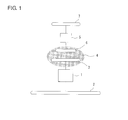
- Fig. 1 illustrates the basic configuration of the power transmission system disclosed in Japanese Unexamined Patent Application Publication (Translation of PCT Application) No. 2009-531009 .
- This power transmission system includes a power transmitting apparatus and a power receiving apparatus.
- the power transmitting apparatus includes a high-frequency voltage generator circuit 1, a passive electrode 2, and an active electrode 3.
- the power receiving apparatus includes a high-frequency voltage load circuit 5, a passive electrode 7, and an active electrode 6.
- the active electrode 3 and the active electrode 6 being arranged to be close to each other with a gap 4 therebetween, these two electrodes are coupled to each other through an electric field.
- the passive electrode of the power transmitting apparatus, the active electrode of the power transmitting apparatus, the active electrode of the power receiving apparatus, and the passive electrode of the power receiving apparatus have a common normal line passing through the centers thereof.
- a power transmitting apparatus includes a first resonant circuit that resonates with an AC signal generated by an AC signal generator and a power feeding electrode.
- a power receiving apparatus includes a power receiving electrode that generates an electric signal, a second resonant circuit that resonates with the electric signal, a rectifier that generates a DC power from the electric signal with which the second resonant circuit is resonating, and a circuit load.
- the active electrode and passive electrode of the power transmitting apparatus are arranged in the same plane, and the active electrode and passive electrode of the power receiving apparatus are arranged so as to face the corresponding electrodes of the power transmitting apparatus with a predetermined separation therebetween.
- the active electrodes of the power transmitting apparatus and the power receiving apparatus are made to be close to each other, thereby forming a strong electric field between the electrodes, and the capacitance generated between the passive electrodes of the power transmitting apparatus and the power receiving apparatus is made to be as high as possible.
- the sizes of the passive electrodes need to be increased.
- the passive electrode of the power transmitting unit, the active electrode of the power transmitting unit, the active electrode of the power receiving unit, and the passive electrode of the power receiving unit are arranged in a vertical direction in a narrow vertically-long space, stray capacitance is likely to become excessively high.
- the power receiving apparatuses are, for example, electronic apparatuses such as a mobile communication terminal and a digital camera. Recently, a reduction in the sizes and an increase in the packaging density of these apparatuses have been required. Under these circumstances, restrictions on the arrangement of the active electrode and the passive electrode have increased. Stray capacitance generated between the active electrode and the passive electrode becomes large, depending on the arrangement relationship between the two electrodes, and as a result, the degree of coupling between the power transmitting apparatus and the power receiving apparatus may decrease, whereby the power transmission efficiency decreases. Further, depending on the arrangement relationship between the active electrode and the conductors of a printed wiring board, a secondary battery, and the like housed in the electronic apparatus, stray capacitance generated between the active electrode and the conductors is large. This not only lowers the power transmission efficiency but also affects the electric characteristics of various circuits formed on the printed wiring board and the battery characteristics of the secondary battery.
- the active electrode and passive electrode of the power transmitting apparatus are not parallel with each other, and the active electrode and passive electrode of the power receiving apparatus are not parallel with each other, stray capacitance is suppressed and a decrease in the degree of coupling is small, whereby high transmission efficiency is obtained.
- the active electrodes can be arranged in such a manner as not to be parallel with the printed wire board within the apparatus, influence on the electric characteristics of various circuits within the apparatus and the battery characteristics of a secondary battery is suppressed.
- the power receiving apparatus side passive electrode or active electrode is provided, for example, along a first surface among six surfaces of a casing of the power receiving apparatus, and each of a plurality of surfaces among second to fifth surfaces neighboring the first surface among the six surfaces is provided with the power receiving apparatus side active electrode or passive electrode.
- the power receiving apparatus further includes a detecting unit that detects an electrode facing the power transmitting apparatus side active electrode among electrodes arranged along second to fifth surfaces neighboring the first surface among six surfaces of a casing of the power receiving apparatus; and a switching unit that connects the electrode facing the power transmitting apparatus side active electrode to the voltage step-down circuit.
- various power receiving apparatuses may be adapted to one type of power transmitting apparatus by preparing jackets corresponding to different types of apparatus.
- the power receiving apparatus main body since it is only required that the power receiving apparatus main body support a contact power receiving method, the power receiving apparatus main body can receive power by itself using a contact method.
- the power transmitting apparatus includes a third flat portion perpendicular to the first flat portion and the second flat portion, and the power transmitting apparatus side active electrode faces the power receiving apparatus side active electrode in a state in which one surface of a casing of the power receiving apparatus is in contact with the third flat portion.
- alignment of the power receiving apparatus with respect to the power transmitting apparatus can easily and reliably be performed by making three surfaces of the power receiving apparatus adjacent to one another be respectively in contact with the first flat portion, the second flat portion, and the third flat portion.
- the third flat portion may be provided with the power transmitting apparatus side passive electrode.
- the first surface of the casing of the power receiving apparatus is not provided with the passive electrode, and a surface (surface adjacent to a surface provided with the active electrode among the four surfaces neighboring the first surface of the power receiving apparatus) of the casing of the power receiving apparatus facing the power transmitting apparatus side passive electrode is provided with the passive electrode, power is transmitted only when the surface provided with the passive electrode of the power receiving apparatus is in contact with the third flat portion of the power transmitting apparatus, whereby safety can be increased.
- a passive electrode may be provided also along a large area surface of the power receiving apparatus, and the second flat portion of the power transmitting apparatus may also be provided with a passive electrode, capacitance generated between the respective passive electrodes of the power transmitting apparatus and the power receiving apparatus can be made to be larger, and the potential of the passive electrodes can be made to be lower.
- the power receiving apparatus can be used whether it is vertically oriented or horizontally oriented with respect to the power transmitting apparatus. Further, since only a necessary active electrode is used among the plurality of active electrodes of the power transmitting apparatus, a potential is not unnecessarily applied to the remaining unnecessary active electrodes.
- the power receiving apparatus when the power receiving apparatus is mounted on the power transmitting apparatus, the power receiving apparatus is prevented from falling from the seat or mounting portion of the power transmitting apparatus, and the power receiving apparatus is reliably mounted at a correct position.
- a power transmitting apparatus a power receiving apparatus, and a wireless power transmission system in which stray capacitance not contributing to power transmission is decreased and the power transmission efficiency is increased without causing increases in the sizes of the apparatuses are realized.
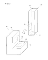
- Fig. 2 illustrates perspective views of a power transmitting apparatus 101 and a power receiving apparatus 201 according to a first embodiment.
- Fig. 3 illustrates side views of the power transmitting apparatus 101 and the power receiving apparatus 201.
- the power transmitting apparatus 101 and the power receiving apparatus 201 form a wireless power transmission system.
- the power transmitting apparatus 101 includes a passive electrode 11 and an active electrode 12, and the power receiving apparatus 201 includes a passive electrode 21 and an active electrode 22.
- a casing 20 of the power receiving apparatus 201 is substantially shaped like a rectangular parallelepiped, and the passive electrode 21 of the power receiving apparatus 201 is provided along a first surface, which has a large area, and the active electrode 22 of the power receiving apparatus 201 is provided along a second surface, which is one of the four surfaces (side surfaces) neighboring the first surface among the six surfaces of the casing.
- a casing 10 of the power transmitting apparatus 101 includes a seat 10D and a backrest 10B.
- the seat 10D and backrest 10B form a mounting portion of the power receiving apparatus 201.
- the passive electrode 11 of the power transmitting apparatus 101 faces the power receiving apparatus side passive electrode 21
- the active electrode 12 of the power transmitting apparatus 101 faces the power receiving apparatus side active electrode 22.
- the seat 10D corresponds to a "first flat portion" of the present invention
- the backrest 10B corresponds to a "second flat portion" of the present invention.
- a high-frequency voltage generator circuit is connected between the power transmitting apparatus side active electrode 12 and the power transmitting apparatus side passive electrode 11.
- a voltage step-down circuit is provided between the power receiving apparatus side active electrode 22 and the power receiving apparatus side passive electrode 21, and a load circuit is connected to the voltage step-down circuit.
- the load circuit is a secondary battery 28.
- the power receiving apparatus 201 is, for example, a mobile electronic apparatus, and the power transmitting apparatus 101 is its charging stand. By mounting the power receiving apparatus 201 on the power transmitting apparatus 101, the internal secondary battery 28 is charged.
- Mobile electronic apparatuses include a mobile phone, a laptop PC, a digital camera, etc.
- Fig. 4 is an equivalent circuit diagram of the wireless power transmission system.
- a high-frequency voltage generator circuit OSC of the power transmitting apparatus 101 generates, for example, a high-frequency voltage with a frequency of about 100 kHz to tens of MHz.
- a voltage step-up circuit 17 formed of a step-up transformer TG and an inductor LG steps up a voltage generated by the high-frequency voltage generator circuit OSC and applies the stepped-up voltage between the passive electrode 11 and the active electrode 12.
- a voltage step-down circuit 25 formed of a step-down transformer TL and an inductor LL is connected between the passive electrode 21 and the active electrode 22 of the power receiving apparatus 201.
- a load circuit RL is connected to the secondary side of the step-down transformer TL.
- the load circuit RL is formed of a rectifying and smoothing circuit and a secondary battery.
- the load circuit RL is connected to the secondary side of the step-down transformer TL.
- the load circuit RL is formed of a rectifying and smoothing circuit and a secondary battery.
- the main surfaces of the active electrode and passive electrode of a power transmitting apparatus are not parallel with each other, and the main surfaces of the active electrode and passive electrode of a power receiving apparatus are not parallel with each other.
- stray capacitance between the active electrodes and stray capacitance between the passive electrodes are suppressed, and decreases in the degrees of coupling between the active electrodes and coupling between the passive electrodes are small, whereby high transmission efficiency is obtained.
- the active electrode 22 can be arranged in such a manner as not to be parallel with the printed wire board within the apparatus, influence on the electric characteristics of various circuits within the apparatus and the battery characteristics of a secondary battery is suppressed.
- the respective active electrodes and the respective passive electrodes of the power transmitting apparatus and the power receiving apparatus can be made to face each other, only by making the power receiving apparatus lean against the backrest and be mounted on the seat of the power transmitting apparatus.
- the power receiving apparatus side active electrode and passive electrode, or the power transmitting apparatus side active electrode and passive electrode need not be substantially perpendicular to each other, and need only be at least substantially not parallel with each other.
- the frequency of an AC voltage generated by the high-frequency voltage generator circuit OSC is set such that the wavelength in a dielectric medium (i.e., air) surrounding the power transmitting apparatus 101 and the power receiving apparatus 201 is longer than the sizes of the power transmitting apparatus 101 and the power receiving apparatus 201. In other words, power is transmitted using a quasi-static electric field. As a result, since energy radiation (dispersion) in the form of electromagnetic radiation is low, power transmission efficiency is increased.
- the frequency of an AC voltage generated by the high-frequency voltage generator circuit OSC is set to be as high as possible within a range in which the radiated electromagnetic energy is smaller than the electric field energy transmitted from the power transmitting apparatus 101 to the power receiving apparatus 201.
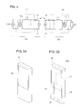
- Fig. 5A is a perspective view of a power receiving apparatus 202 that forms part of a wireless power transmission system according to a second embodiment
- Fig. 5B illustrates the arrangement of various electrodes provided in the casing.
- the casing 20 of the power receiving apparatus 202 is substantially shaped like a rectangular parallelepiped, and the passive electrode 21 of the power receiving apparatus 202 is provided along a first surface, having a large area, of the casing 20, and power receiving apparatus side active electrodes 22, 23, and 24 are provided along three of the four surfaces (side surfaces) neighboring the first surface among the six surfaces of the casing.
- a liquid crystal display panel 26 is provided in parallel with the first surface.
- a circuit substrate is provided within the casing 20 in parallel with the first surface.
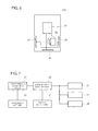
- Fig. 6 is a schematic circuit diagram of the power receiving apparatus 202.
- the primary side of the step-down transformer TL is connected between the passive electrode 21 and the three active electrodes 22, 23, and 24.
- the load circuit RL is connected to the secondary side of the step-down transformer TL.
- the three active electrodes 22, 23, and 24, which are commonly connected, have the same potential.
- Fig. 7 is a circuit block diagram of the power receiving apparatus 202.
- a voltage step-down circuit 25 corresponds to the step-down transformer TL illustrated in Fig. 6 .
- a rectifying and smoothing circuit 27 rectifies and smoothes the output voltage of the voltage step-down circuit 25 and applies a charging voltage to the secondary battery 28.
- the rectifying and smoothing circuit 27 and the secondary battery 28 correspond to the load circuit RL.
- Figs. 8A and 8B are perspective views of the wireless power transmission system according to the second embodiment, illustrating the types of usage.
- Fig. 8A illustrates an example in which the power receiving apparatus 202 is mounted on the seat 10D of the power transmitting apparatus 102, in a vertical orientation.
- Fig. 8B illustrates an example in which the power receiving apparatus 202 is mounted on the seat 10D of the power transmitting apparatus 102, in a horizontal orientation.
- the basic configuration of a power transmitting apparatus 102 is the same as that of the power transmitting apparatus 101 shown in the first embodiment.
- the power receiving apparatus 202 can be mounted in three ways.
- the power receiving apparatus side active electrodes may be provided along all the surfaces of the four surfaces (side surfaces) neighboring the first surface among the six surfaces of the casing. Further, the power receiving apparatus side active electrodes provided along all the four surfaces may be electrically connected (circularly connected) to one another.
- a single passive electrode and a plurality of active electrodes are provided in the examples illustrated in Figs. 5A to 8B , the relationship between the passive electrode and the active electrode may be reversed.
- a single active electrode may be provided along the first surface of the casing and respective passive electrodes may be provided along the plurality of surfaces neighboring the first surface.
- Fig. 9 is a circuit block diagram of a power receiving apparatus which is part of a wireless power transmission system according to a third embodiment.
- the difference from the power receiving apparatus 202 shown in the second embodiment is that the three active electrodes 22, 23, and 24 are formed to be selectively connected to the voltage step-down circuit 25 using a selector switch 29.
- the selector switch 29 selects one of the active electrodes 22, 23, and 24 in accordance with the detection result of a sensor unit 30.
- the sensor unit 30 which includes a sensor that detects the direction of gravity acceleration, the active electrode of the power receiving apparatus 202 facing the active electrode of a power transmitting apparatus is detected.
- the selector switch 29 selects the power receiving apparatus side active electrode facing the active electrode of the power transmitting apparatus.
- the active electrodes which have not been selected may be connected to the passive electrode. This allows the total area of the passive electrodes to be increased.
- the sensor unit 30 also includes a human body sensor.
- the human body sensor detects a human body, i.e., a human body is in proximity of the power receiving apparatus, the selector switch 29 makes all the active electrodes 22, 23, and 24 be in a non-selected state. Thereby, charging is terminated. Since the power transmitting apparatus, by detecting that power transmitted to the power receiving apparatus has become zero, terminates application of a voltage between the active electrode and passive electrode of the power transmitting apparatus, a high potential is not applied between the active electrode and passive electrode of both the power transmitting apparatus and the power receiving apparatus, whereby safety is increased.
- selectable power receiving apparatus side active electrodes may be provided along all the four surfaces (side surfaces) neighboring the first surface among the six surfaces of the casing.
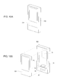
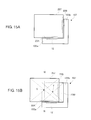
- Fig. 10A is a perspective view of a power receiving apparatus which is part of a wireless power transmission system according to a fourth embodiment.
- Fig. 10B is a perspective view of a state in which a power receiving apparatus main body 301 is separated from a jacket 302. This power receiving apparatus is formed of the power receiving apparatus main body 301 and the jacket 302 housing the power receiving apparatus main body 301.
- the jacket 302 includes power receiving apparatus side active electrodes 32, 33, and 34, a power receiving apparatus side passive electrode 31, a control circuit 36, and a connector 35 for supplying an output voltage of a voltage step-down circuit.
- the power receiving apparatus main body 301 includes power receiving apparatus main body side electrodes that are in contact with and electrically connected to the jacket side connector 35, and a load circuit electrically connected to the power receiving apparatus main body side electrodes.
- the control circuit 36 corresponds to the voltage step-down circuit in each of the embodiments described above.
- terminal electrodes in contact with the electrodes of the power receiving apparatus main body 301 may be provided instead of the connector 35.
- various power receiving apparatuses may be adapted to be used with one type of power transmitting apparatus by preparing jackets corresponding to different types of apparatus.
- the power receiving apparatus main body 301 may be an apparatus that can be mounted alone on an existing contact charging stand.
- a power receiving apparatus main body using a contact charging method may be combined with a jacket so as to form a power receiving apparatus using a wireless charging method.
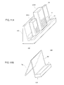
- Fig. 11A is a perspective view of a wireless power transmission system, as a type of usage, according to a fifth embodiment.
- a power transmitting apparatus 103 has a sufficiently large size to mount a plurality of power receiving apparatuses 201A and 201B.
- the power transmitting side passive electrode 11 and active electrode 12 are formed in such a manner as to extend in the direction of a valley formed by the seat 10D and the backrest 10B so as to allow a power receiving apparatus to be mounted anywhere on the seat 10D of the power transmitting apparatus 103.
- Fig. 11B is a perspective view of another power transmitting apparatus 104 according to the fifth embodiment.
- the backrest 10B of the power transmitting apparatus 104 is made of a transparent substrate, and a transparent passive electrode is formed using, for example, ITO in the transparent substrate.
- the power transmitting apparatus 104 is used in such a manner as to stand on a table, for example, by opening a support member 10L backward behind the backrest 10B.
- Fig. 12A is a perspective view of a power transmitting apparatus 106 according to a sixth embodiment.
- Fig. 12B is a perspective view of a power receiving apparatus 206 which is mounted on the power transmitting apparatus 106.
- the power transmitting apparatus 106 and the power receiving apparatus 206 form a wireless power transmission system.
- the power transmitting apparatus 106 includes the backrest 10B provided with the passive electrode 11, the seat 10D provided with the active electrode 12, and a side wall 10S.
- the respective inner surfaces of the backrest 10B, the seat 10D, and the side wall 10S are perpendicular to one another.
- the backrest 10B of the power transmitting apparatus 106 is formed of a transparent substrate, and the passive electrode 11 made of, for example, ITO is formed in the substrate.
- a high-frequency voltage generator circuit is connected between the power transmitting apparatus side active electrode 12 and passive electrode 11.
- the seat 10D corresponds to the "first flat portion” of the present invention
- the backrest 10B corresponds to the "second flat portion” of the present invention
- the side wall 10S corresponds to a "third flat portion” of the present invention.
- the casing of the power receiving apparatus 206 is substantially shaped like a rectangular parallelepiped, and the passive electrode 21 is provided along a first surface S1, having a large area, of the casing 20, and the active electrode 22 is provided along a second surface S2, which is one of the four surfaces (side surfaces) neighboring the first surface S1 among the six surfaces of the casing.
- a voltage step-down circuit is connected between the power receiving apparatus side active electrode 22 and passive electrode 21, and a load circuit is connected to the voltage step-down circuit.
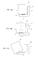
- Fig. 13A is a front view illustrating a state in which the power receiving apparatus 206 is normally mounted on the power transmitting apparatus 106.
- the power receiving apparatus 206 is mounted on the mounting portion of the power transmitting apparatus 106 such that the second surface S2 of the power receiving apparatus 206 is placed on the seat 10D of the power transmitting apparatus 106 and a third surface S3 of the power receiving apparatus 206 is in contact with the side wall 10S.
- the passive electrode 11 of the power transmitting apparatus 106 faces the power receiving apparatus side passive electrode 21, and the active electrode 12 of the power transmitting apparatus 106 faces the power receiving apparatus side active electrode 22.
- a broken line W-W is a vertical line passing through the center of gravity of the power receiving apparatus 206.
- the vertical line W-W passes beyond the edge of the seat 10D of the power transmitting apparatus 106, the power receiving apparatus 206 will fall from the seat 10D of the power transmitting apparatus 106, as illustrated in Fig. 13C .
- the power receiving apparatus since the power receiving apparatus is wide enough so that a point P at which a line perpendicular to the seat 10D and passing through the center of gravity of the power receiving apparatus 206 intersects with the seat 10D is farther from the side wall 10S than the center Q of the seat 10D when the third surface S3 of the power receiving apparatus is in contact with the side wall 10S of the power transmitting apparatus, the power receiving apparatus 206 is likely to fall from the seat 10D of the power transmitting apparatus 106 when the third surface S3 of the power receiving apparatus 206 is spaced apart from the side wall 10S.
- the operator intentionally or unintentionally mounts the power receiving apparatus 206 so as to make the third surface S3 of the power receiving apparatus 206 be in contact with the side wall 10S of the power transmitting apparatus 106.
- the dimensions of the power receiving apparatus relative to the seat 10D are designed so as to motivate the user to position the power receiving apparatus with its third surface S3 in contact with the side wall 10S of the power transmitting apparatus.
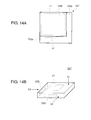
- Fig. 14A is a plan view (not a front view) of a power transmitting apparatus 107 according to a seventh embodiment.
- Fig. 14B is a perspective view of a power receiving apparatus 207 according to the seventh embodiment.
- the power transmitting apparatus 107 and the power receiving apparatus 207 form a wireless power transmission system.
- the power transmitting apparatus 107 includes a mounting portion 10M provided with the passive electrode 11, a first sidewall 10Sa provided with the active electrode 12, and a second sidewall 10Sb.
- the upper surface of the mounting portion 10M and the respective inner surfaces of the first sidewall 10Sa and the second sidewall 10Sb are perpendicular to one another.
- a high-frequency voltage generator circuit is connected between the power transmitting apparatus side active electrode 12 and the power transmitting apparatus side passive electrode 11.
- the casing 20 of the power receiving apparatus 207 is substantially shaped like a rectangular parallelepiped, and the passive electrode 21 is provided along the first surface S1 having a large area, and active electrodes 22A and 22B are respectively provided along the second surface S2 and the third surface S3 adjacent to each other among the four surfaces (side surfaces) neighboring the first surface among the six surfaces of the casing.
- a voltage step-down circuit is connected between the passive electrode 21 and the active electrodes 22A and 22B, and a load circuit is connected to the voltage step-down circuit.
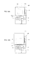
- Fig. 15A is a front view illustrating a state in which the power receiving apparatus 207 is normally mounted on the power transmitting apparatus 107.
- the power receiving apparatus 207 is mounted on the mounting portion of the power transmitting apparatus 107 such that the first surface S1 of the power receiving apparatus 207 is placed on the mounting portion 10M of the power transmitting apparatus 107, the second surface S2 of the power receiving apparatus 207 is in contact with the first sidewall 10Sa of the power transmitting apparatus 107, and the third surface S3 of the power receiving apparatus 207 is in contact with the second sidewall 10Sb of the power transmitting apparatus 107.
- the passive electrode 11 of the power transmitting apparatus 107 faces the power receiving apparatus side passive electrode 21, and the active electrode 12 of the power transmitting apparatus 107 faces the power receiving apparatus side active electrode 22A.
- the mounting portion 10M corresponds to the "second flat portion” of the present invention
- the first sidewall 10Sa corresponds to the "first flat portion” of the present invention
- the second sidewall 10Sb corresponds to the "third flat portion” of the present invention.
- a broken line W-W is a vertical line which passes through the center of gravity of the power receiving apparatus 207 and is parallel with an edge of the mounting portion 10M of the power transmitting apparatus 107.
- the vertical line W-W passes beyond the edge of the seat 10M of the power transmitting apparatus 107, the power receiving apparatus 207 will fall from the seat 10M of the power transmitting apparatus 107.
- the power receiving apparatus 207 is likely to fall from the seat 10M of the power transmitting apparatus 107 when the third surface S3 of the power receiving apparatus 207 is spaced apart from the second side wall 10Sb.
- the operator intentionally or unintentionally mounts the power receiving apparatus 207 so as to make the second surface S2 or the third surface S3 of the power receiving apparatus 207 be in contact with the second side wall 10Sb of the power transmitting apparatus 107.
- the power receiving apparatus 207 may be mounted on the power transmitting apparatus 107 in such a manner as to be turned clockwise by 90 degrees from the state illustrated in Fig. 15A .
- the passive electrode 11 of the power transmitting apparatus 107 faces the power receiving apparatus side passive electrode 21, and the active electrode 12 of the power transmitting apparatus 107 faces the power receiving apparatus side active electrode 22B.
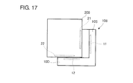
- Fig. 16A is a front view of a power transmitting apparatus 108 according to an eighth embodiment.
- Fig. 16B is a perspective view of a power receiving apparatus 208 according to the eighth embodiment.
- the power transmitting apparatus 108 and the power receiving apparatus 208 form a wireless power transmission system.
- the power transmitting apparatus 108 includes the backrest 10B, the seat 10D provided with the active electrode 12, and the side wall 10S provided with the passive electrode 11.
- the respective inner surfaces of the backrest 10B, the seat 10D, and the side wall 10S are perpendicular to one another.
- a high-frequency voltage generator circuit is connected between the power transmitting apparatus side active electrode 12 and passive electrode 11.
- the casing of the power receiving apparatus 208 is substantially shaped like a rectangular parallelepiped, and the active electrode 22 and the passive electrode 21 are respectively provided along surfaces adjacent to each other among the four surfaces (side surfaces) neighboring a surface having a large area among the six surfaces of the casing.
- a voltage step-down circuit is connected between the active electrodes 22 and the passive electrode 21, and a load circuit is connected to the voltage step-down circuit.
- the seat 10D corresponds to the "first flat portion” of the present embodiment
- the backrest 10B corresponds to the "second flat portion” of the present invention
- the side wall 10S corresponds to the "third flat portion” of the present invention.
- the passive electrode 21 can be provided along a surface adjacent to the first surface S1. In this case, power is transmitted only when a surface provided with the passive electrode 21 of the power receiving apparatus 208 is in contact with the third flat portion of the power transmitting apparatus 108, whereby safety is increased.
- the shape of the passive electrode of the power receiving apparatus 208 can be made to be small and slim, but a variation in the potential of the passive electrode is large.
- the passive electrode 21 may also be provided along the large-area surface of the power receiving apparatus 208, and the backrest 10B of the power transmitting apparatus 108 may also be provided with a passive electrode.
- capacitance generated between the respective passive electrodes of the power transmitting apparatus 108 and the power receiving apparatus 208 can be made to be larger than the case in which the passive electrode is provided only on the first surface S1 of the power receiving apparatus 208, and the potential of the passive electrodes can be made to be lower.
- Fig. 17 is a front view illustrating a state in which the power receiving apparatus 208 is mounted on the power transmitting apparatus 108.
- the passive electrode 11 of the power transmitting apparatus 108 faces the passive electrode 21 of the power receiving apparatus 208
- the active electrode 12 of the power transmitting apparatus 108 faces the active electrode 22 of the power receiving apparatus 208.
- a power transmitting apparatus is provided with a plurality of active electrodes, and the active electrodes are made to be effective in accordance with an orientation in which a power receiving apparatus is mounted on the power transmitting apparatus.
- Fig. 18A is a plan view of a power transmitting apparatus 109
- Fig. 18B is a plan view illustrating a state in which a power receiving apparatus 209 is mounted on the power transmitting apparatus 109.
- the power transmitting apparatus 109 includes the mounting portion 10M provided with the passive electrode 11, the first sidewall 10Sa provided with an active electrode 12A, and the second sidewall 10Sb provided with an active electrode 12B.
- the upper surface of the mounting portion 10M and the inner surfaces of the first sidewall 10Sa and the second sidewall 10Sb are perpendicular to one another.
- a high-frequency voltage generator circuit is connected between the power transmitting apparatus side active electrode 12 and passive electrode 11.
- the mounting portion 10M corresponds to the "second flat portion” of the present invention
- the first sidewall 10Sa corresponds to the "first flat portion” of the present invention
- the second sidewall 10Sb corresponds to the "third flat portion” of the present invention.
- the casing of the power receiving apparatus 209 is substantially shaped like a rectangular parallelepiped.
- the passive electrode 21 is provided along a surface having a large area, and one side surface among the six surfaces of the casing is provided with the active electrode 22.
- a voltage step-down circuit is connected between the active electrodes 22 and the passive electrode 21, and a load circuit is connected to the voltage step-down circuit.
- the power transmitting apparatus 109 includes a voltage detecting circuit 41 that detects a voltage applied to the active electrodes 12A and 12B, a transfer switch 42 that selects, among the active electrodes 12A and 12B, one to which a voltage is to be applied, a driving control circuit 40, and the like.
- the driving control circuit 40 by detecting which of the active electrodes 12A and 12B is facing the active electrode of the power receiving apparatus on the basis of the voltage detected by the voltage detecting circuit 41 of the driving control circuit 40, selectively switches the transfer switch 42 so as to apply a high-frequency voltage to the corresponding active electrode. In the state illustrated in Fig. 18B , the transfer switch 42 is switched so as to select the active electrode 12A.
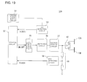
- Fig. 19 is a block diagram of the power transmitting apparatus 109.
- a driving power supply circuit 51 is a power supply circuit which receives power from a commercial power source and generates a fixed DC voltage (for example, DC 5V).
- a control circuit 52 controls the units described below through input and output of signals from and to the units.
- a driving control circuit 55 controls switching of the switching device of a switching circuit 56 in accordance with an ON/OFF signal output from the control circuit 52.
- the switching circuit 56 alternately drives the input of a voltage step-up circuit 37.
- a DCI detecting circuit 53 detects a driving current (i.e., amount of current supplied from the driving power supply circuit 51 to the voltage step-up circuit 37) flowing through the switching circuit 56.
- the control circuit 52 reads this detection signal V (DCI).
- An ACV detecting circuit 58 divides a voltage applied to the active electrode 12A or the active electrode 12B using capacitance, and generates a detection signal V (ACV), which is a DC voltage obtained by rectifying the divided AC voltage.
- the control circuit 52 reads this detection signal V (ACV).
- Fig. 20 is a flowchart illustrating processing steps for detecting mounting of a power receiving apparatus on a power transmitting apparatus and subsequent processing steps, among processing steps performed by the control circuit 52 illustrated in Fig. 19 .
- a high-frequency voltage having a monitoring frequency is generated (S11 ⁇ S12). Then the transfer switch 42 is made to select the active electrode 12A and the driving current DCI is detected (S13 ⁇ S14). When the driving current DCI does not exceed a threshold DCIth2, the transfer switch 42 is made to select the active electrode 12B, and the driving current DCI is detected (S16 ⁇ S17 ⁇ S18).
- the threshold DCIth2 is a value for detecting that a power receiving apparatus which is to receive power has been mounted. Even when any metal object is mounted, by generating the high-frequency voltage having a monitoring frequency, no resonance occurs and hence almost no capacitance coupling occurs, resulting in no power transmission. Hence, safety is maintained.
- the threshold DCIth3 is a value for detecting the driving current corresponding to time to stop power transmission. For example, the driving current DCI becomes below the threshold DCIth3 when the secondary battery included in the load circuit has entered a fully charged state or when the power receiving apparatus has been removed. When the driving current DCI has become below the threshold DCIth3, driving is stopped (S22).
- the power transmitting apparatus 109 is provided with the two active electrodes 12A and 12B, and one of the active electrodes 12A and 12B of the power transmitting apparatus 109 is selected in accordance with the orientation of the power receiving apparatus 209 mounted on the power transmitting apparatus 109.
Landscapes
- Engineering & Computer Science (AREA)
- Computer Networks & Wireless Communication (AREA)
- Power Engineering (AREA)
- Signal Processing (AREA)
- Charge And Discharge Circuits For Batteries Or The Like (AREA)
- Near-Field Transmission Systems (AREA)
Applications Claiming Priority (2)
| Application Number | Priority Date | Filing Date | Title |
|---|---|---|---|
| JP2010144210 | 2010-06-24 | ||
| JP2010243345A JP5152298B2 (ja) | 2010-06-24 | 2010-10-29 | 送電装置、受電装置及びワイヤレス電力伝送システム |
Publications (3)
| Publication Number | Publication Date |
|---|---|
| EP2400633A2 true EP2400633A2 (de) | 2011-12-28 |
| EP2400633A3 EP2400633A3 (de) | 2014-05-07 |
| EP2400633B1 EP2400633B1 (de) | 2016-05-11 |
Family
ID=44918567
Family Applications (1)
| Application Number | Title | Priority Date | Filing Date |
|---|---|---|---|
| EP11170980.4A Not-in-force EP2400633B1 (de) | 2010-06-24 | 2011-06-22 | Stromübertragungsvorrichtung, Stromempfangsvorrichtung und drahtloses Stromübertragungssystem |
Country Status (4)
| Country | Link |
|---|---|
| US (1) | US8772978B2 (de) |
| EP (1) | EP2400633B1 (de) |
| JP (1) | JP5152298B2 (de) |
| CN (1) | CN102299572B (de) |
Cited By (1)
| Publication number | Priority date | Publication date | Assignee | Title |
|---|---|---|---|---|
| WO2015052003A1 (en) * | 2013-10-10 | 2015-04-16 | Koninklijke Philips N.V. | Wireless capacitive power receiving module |
Families Citing this family (25)
| Publication number | Priority date | Publication date | Assignee | Title |
|---|---|---|---|---|
| US9496743B2 (en) | 2010-09-13 | 2016-11-15 | Semiconductor Energy Laboratory Co., Ltd. | Power receiving device and wireless power feed system |
| WO2013024406A2 (en) * | 2011-08-16 | 2013-02-21 | Koninklijke Philips Electronics N.V. | Transparent capacitive wireless powering system |
| WO2013105312A1 (ja) * | 2012-01-10 | 2013-07-18 | 株式会社村田製作所 | 電力伝送システム |
| GB2513264A (en) * | 2012-02-22 | 2014-10-22 | Murata Manufacturing Co | Power transmission device and power transmission control method |
| US20130280557A1 (en) * | 2012-04-24 | 2013-10-24 | Electronics And Telecommunications Research Institute | Ultrasonic rechargeable battery module and ultrasonic rechargeable battery apparatus of polyhedral structure including the same |
| CN103597709B (zh) * | 2012-05-09 | 2015-11-25 | 株式会社村田制作所 | 无线电力输送系统 |
| JP5980329B2 (ja) * | 2012-07-02 | 2016-08-31 | 富士機械製造株式会社 | 静電結合方式非接触給電装置 |
| CN103683365B (zh) * | 2012-09-26 | 2015-11-25 | 荆涛 | 电子设备的充电系统和充电底座 |
| JP5836287B2 (ja) * | 2013-01-07 | 2015-12-24 | 東芝テック株式会社 | 電力伝送装置 |
| JP5979301B2 (ja) * | 2013-03-01 | 2016-08-24 | 株式会社村田製作所 | 送電装置および受電装置 |
| JP6323054B2 (ja) * | 2013-03-08 | 2018-05-16 | Tdk株式会社 | 給電装置、受電装置、及び、ワイヤレス電力伝送装置 |
| JP6127777B2 (ja) * | 2013-06-28 | 2017-05-17 | ソニー株式会社 | 給電装置および給電システム |
| JP5889250B2 (ja) | 2013-07-12 | 2016-03-22 | 東芝テック株式会社 | 電力伝送装置、電力伝送装置用の送電装置及び受電装置 |
| KR102126713B1 (ko) * | 2013-08-13 | 2020-06-25 | 삼성전자주식회사 | 무선 전력 전송 시스템에서 무선 충전 제어 방법 및 장치 |
| TWI528673B (zh) | 2014-01-02 | 2016-04-01 | 鴻騰精密科技股份有限公司 | 無線充電基座 |
| US9263910B2 (en) | 2014-02-06 | 2016-02-16 | Lenovo (Singapore) Pte. Ltd. | Wireless charging system for multi-mode device |
| WO2015198123A1 (en) * | 2014-06-26 | 2015-12-30 | Eggtronic S.R.L. | A method and an apparatus for transferring electrical power |
| JP6140786B2 (ja) * | 2015-11-02 | 2017-05-31 | 東芝テック株式会社 | 電力伝送装置 |
| KR102620178B1 (ko) * | 2017-01-26 | 2024-01-03 | 삼성전자주식회사 | 전자 장치 및 그의 동작 방법 |
| KR102349757B1 (ko) * | 2017-06-14 | 2022-01-11 | 삼성전자주식회사 | 생체 센서의 전극을 이용한 충전 방법 및 이를 적용한 전자 장치 |
| KR101957576B1 (ko) * | 2017-07-12 | 2019-03-12 | 중앙대학교 산학협력단 | 손실 에너지 하베스팅 장치 |
| US10937262B2 (en) | 2017-08-30 | 2021-03-02 | Sensormatic Electronics, LLC | Door system with power management system and method of operation thereof |
| US10968669B2 (en) * | 2017-08-30 | 2021-04-06 | Sensormatic Electronics, LLC | System and method for inductive power transfer to door |
| US10943415B2 (en) | 2017-08-30 | 2021-03-09 | Sensormatic Electronics, LLC | System and method for providing communication over inductive power transfer to door |
| TWI666807B (zh) * | 2018-07-12 | 2019-07-21 | 鑫東龍安防股份有限公司 | 具無線能源獲取功能的電池與電池套組 |
Citations (2)
| Publication number | Priority date | Publication date | Assignee | Title |
|---|---|---|---|---|
| JP2009531009A (ja) | 2006-03-21 | 2009-08-27 | Tmms株式会社 | 誘電性媒質を介した部分的インフルエンスによるエネルギー搬送装置 |
| JP2009296857A (ja) | 2008-06-09 | 2009-12-17 | Sony Corp | 伝送システム、給電装置、受電装置、及び伝送方法 |
Family Cites Families (19)
| Publication number | Priority date | Publication date | Assignee | Title |
|---|---|---|---|---|
| JP2671809B2 (ja) | 1994-06-30 | 1997-11-05 | 日本電気株式会社 | 非接触型充電装置 |
| JPH1140207A (ja) | 1997-07-22 | 1999-02-12 | Sanyo Electric Co Ltd | パック電池と充電台 |
| US6879809B1 (en) * | 1998-04-16 | 2005-04-12 | Motorola, Inc. | Wireless electrostatic charging and communicating system |
| US6282407B1 (en) * | 1998-04-16 | 2001-08-28 | Motorola, Inc. | Active electrostatic transceiver and communicating system |
| US6275681B1 (en) * | 1998-04-16 | 2001-08-14 | Motorola, Inc. | Wireless electrostatic charging and communicating system |
| FR2875649B1 (fr) | 2004-09-21 | 2010-09-24 | Henri Bondar | Dispositif de transport a distance par influence de l'energie electrique sans fil ni terre comme conducteur de l iaison |
| WO2007017848A2 (en) | 2005-08-11 | 2007-02-15 | N-Trig Ltd. | Apparatus for object information detection and methods of using same |
| US7511452B2 (en) | 2005-12-05 | 2009-03-31 | Research In Motion Limited | Portable electronic device and capacitive charger providing data transfer and associated methods |
| EP1926223B1 (de) * | 2006-11-21 | 2018-02-28 | Sony Corporation | Kommunikationssystem und kommunikationsvorrichtung |
| JP2008211951A (ja) | 2007-02-28 | 2008-09-11 | Brother Ind Ltd | 非接触型充電器と非接触型充電装置 |
| FR2920061A1 (fr) | 2007-08-17 | 2009-02-20 | Patrick Camurati | Procede et dispositif de transport, distribution et gestion de l'energie electrique par couplage longitudinal a distance en champ proche entre dipoles electriques |
| JP2009089520A (ja) | 2007-09-28 | 2009-04-23 | Takenaka Komuten Co Ltd | 電力供給システム |
| JP3140996U (ja) | 2008-02-06 | 2008-04-17 | 羅貫誠 | 小型電池充電機 |
| JP5267555B2 (ja) * | 2008-03-27 | 2013-08-21 | 旭硝子株式会社 | エレクトレットおよび静電誘導型変換素子 |
| EP2266795B1 (de) * | 2008-04-17 | 2015-07-01 | Asahi Glass Company, Limited | Elektret und wandler mit elektrostatischer induktion |
| JP5354029B2 (ja) * | 2009-06-25 | 2013-11-27 | 株式会社村田製作所 | 電力伝送システム及び非接触充電装置 |
| JP5035477B1 (ja) * | 2009-06-25 | 2012-09-26 | 株式会社村田製作所 | 電力伝送システム及び非接触充電装置 |
| CN102460900B (zh) * | 2009-06-25 | 2014-07-30 | 株式会社村田制作所 | 功率传送系统和非接触充电装置 |
| JP5093369B2 (ja) * | 2010-07-28 | 2012-12-12 | 株式会社村田製作所 | 送電装置、受電装置および電力伝送システム |
-
2010
- 2010-10-29 JP JP2010243345A patent/JP5152298B2/ja not_active Expired - Fee Related
-
2011
- 2011-06-21 US US13/165,542 patent/US8772978B2/en not_active Expired - Fee Related
- 2011-06-22 EP EP11170980.4A patent/EP2400633B1/de not_active Not-in-force
- 2011-06-22 CN CN201110168988.9A patent/CN102299572B/zh not_active Expired - Fee Related
Patent Citations (2)
| Publication number | Priority date | Publication date | Assignee | Title |
|---|---|---|---|---|
| JP2009531009A (ja) | 2006-03-21 | 2009-08-27 | Tmms株式会社 | 誘電性媒質を介した部分的インフルエンスによるエネルギー搬送装置 |
| JP2009296857A (ja) | 2008-06-09 | 2009-12-17 | Sony Corp | 伝送システム、給電装置、受電装置、及び伝送方法 |
Cited By (1)
| Publication number | Priority date | Publication date | Assignee | Title |
|---|---|---|---|---|
| WO2015052003A1 (en) * | 2013-10-10 | 2015-04-16 | Koninklijke Philips N.V. | Wireless capacitive power receiving module |
Also Published As
| Publication number | Publication date |
|---|---|
| US20110316353A1 (en) | 2011-12-29 |
| CN102299572A (zh) | 2011-12-28 |
| JP5152298B2 (ja) | 2013-02-27 |
| US8772978B2 (en) | 2014-07-08 |
| EP2400633B1 (de) | 2016-05-11 |
| EP2400633A3 (de) | 2014-05-07 |
| JP2012029548A (ja) | 2012-02-09 |
| CN102299572B (zh) | 2014-09-03 |
Similar Documents
| Publication | Publication Date | Title |
|---|---|---|
| EP2400633B1 (de) | Stromübertragungsvorrichtung, Stromempfangsvorrichtung und drahtloses Stromübertragungssystem | |
| EP2683054B1 (de) | Drahtloses System mit mehreren Ladegeräten und Steuerverfahren dafür | |
| CN102570630B (zh) | 无线功率传输设备及其无线功率传输系统 | |
| CN101515725B (zh) | 非接触式充电系统及其控制方法 | |
| EP2553791B1 (de) | Drahtloses aufladeset | |
| US9866042B2 (en) | Electronic apparatus and wireless power transmission system | |
| US9755460B2 (en) | Power reception device, power transmission device and wireless power transmission system | |
| US20110248575A1 (en) | Television system with wireless power transmission function, television set, and set-top box | |
| US9831710B2 (en) | Electric power transmitting apparatus and method for controlling electric power transmission | |
| KR20140099822A (ko) | 무선 전력 전송장치 및 이를 구비하는 무선충전시스템 | |
| US9319107B2 (en) | Wireless power transmission system | |
| US9577475B2 (en) | Electronic device, feed unit, and feed system for reliably informing user of electronic device state during wireless electric power transmission | |
| EP3232451B1 (de) | Abschirmung für einen drahtlosen stromsender | |
| US10931145B2 (en) | Wireless power receiver | |
| WO2013080802A1 (ja) | 電子機器および給電システム | |
| KR20180032349A (ko) | 코일 모듈 및 그를 이용한 무선 전력 송신 장치 | |
| JP5601152B2 (ja) | ワイヤレス電力伝送システムおよび送電装置 | |
| JP2012143093A (ja) | 近接無線充電acアダプタ | |
| JP2017005952A (ja) | 非接触電力送電装置、非接触電力受電装置、及び、非接触電力伝送システム | |
| JP2013021822A (ja) | アンテナ |
Legal Events
| Date | Code | Title | Description |
|---|---|---|---|
| AK | Designated contracting states |
Kind code of ref document: A2 Designated state(s): AL AT BE BG CH CY CZ DE DK EE ES FI FR GB GR HR HU IE IS IT LI LT LU LV MC MK MT NL NO PL PT RO RS SE SI SK SM TR |
|
| AX | Request for extension of the european patent |
Extension state: BA ME |
|
| PUAI | Public reference made under article 153(3) epc to a published international application that has entered the european phase |
Free format text: ORIGINAL CODE: 0009012 |
|
| REG | Reference to a national code |
Ref country code: DE Ref legal event code: R079 Ref document number: 602011026339 Country of ref document: DE Free format text: PREVIOUS MAIN CLASS: H02J0017000000 Ipc: H02J0007000000 |
|
| PUAL | Search report despatched |
Free format text: ORIGINAL CODE: 0009013 |
|
| AK | Designated contracting states |
Kind code of ref document: A3 Designated state(s): AL AT BE BG CH CY CZ DE DK EE ES FI FR GB GR HR HU IE IS IT LI LT LU LV MC MK MT NL NO PL PT RO RS SE SI SK SM TR |
|
| AX | Request for extension of the european patent |
Extension state: BA ME |
|
| RIC1 | Information provided on ipc code assigned before grant |
Ipc: H02J 7/02 20060101ALI20140331BHEP Ipc: H04B 5/00 20060101ALI20140331BHEP Ipc: H02J 7/00 20060101AFI20140331BHEP |
|
| 17P | Request for examination filed |
Effective date: 20141106 |
|
| RBV | Designated contracting states (corrected) |
Designated state(s): AL AT BE BG CH CY CZ DE DK EE ES FI FR GB GR HR HU IE IS IT LI LT LU LV MC MK MT NL NO PL PT RO RS SE SI SK SM TR |
|
| 17Q | First examination report despatched |
Effective date: 20150703 |
|
| GRAP | Despatch of communication of intention to grant a patent |
Free format text: ORIGINAL CODE: EPIDOSNIGR1 |
|
| INTG | Intention to grant announced |
Effective date: 20151204 |
|
| RIN1 | Information on inventor provided before grant (corrected) |
Inventor name: KABUMOTO, MIYAKO Inventor name: GOMA, SHINJI Inventor name: ICHIKAWA, KEIICHI Inventor name: KATO, KAZUYA |
|
| GRAR | Information related to intention to grant a patent recorded |
Free format text: ORIGINAL CODE: EPIDOSNIGR71 |
|
| GRAS | Grant fee paid |
Free format text: ORIGINAL CODE: EPIDOSNIGR3 |
|
| GRAA | (expected) grant |
Free format text: ORIGINAL CODE: 0009210 |
|
| INTG | Intention to grant announced |
Effective date: 20160322 |
|
| AK | Designated contracting states |
Kind code of ref document: B1 Designated state(s): AL AT BE BG CH CY CZ DE DK EE ES FI FR GB GR HR HU IE IS IT LI LT LU LV MC MK MT NL NO PL PT RO RS SE SI SK SM TR |
|
| REG | Reference to a national code |
Ref country code: GB Ref legal event code: FG4D |
|
| REG | Reference to a national code |
Ref country code: CH Ref legal event code: EP |
|
| REG | Reference to a national code |
Ref country code: AT Ref legal event code: REF Ref document number: 799349 Country of ref document: AT Kind code of ref document: T Effective date: 20160515 |
|
| REG | Reference to a national code |
Ref country code: IE Ref legal event code: FG4D |
|
| REG | Reference to a national code |
Ref country code: DE Ref legal event code: R096 Ref document number: 602011026339 Country of ref document: DE |
|
| REG | Reference to a national code |
Ref country code: LT Ref legal event code: MG4D |
|
| REG | Reference to a national code |
Ref country code: NL Ref legal event code: MP Effective date: 20160511 |
|
| PG25 | Lapsed in a contracting state [announced via postgrant information from national office to epo] |
Ref country code: NL Free format text: LAPSE BECAUSE OF FAILURE TO SUBMIT A TRANSLATION OF THE DESCRIPTION OR TO PAY THE FEE WITHIN THE PRESCRIBED TIME-LIMIT Effective date: 20160511 Ref country code: LT Free format text: LAPSE BECAUSE OF FAILURE TO SUBMIT A TRANSLATION OF THE DESCRIPTION OR TO PAY THE FEE WITHIN THE PRESCRIBED TIME-LIMIT Effective date: 20160511 Ref country code: FI Free format text: LAPSE BECAUSE OF FAILURE TO SUBMIT A TRANSLATION OF THE DESCRIPTION OR TO PAY THE FEE WITHIN THE PRESCRIBED TIME-LIMIT Effective date: 20160511 Ref country code: NO Free format text: LAPSE BECAUSE OF FAILURE TO SUBMIT A TRANSLATION OF THE DESCRIPTION OR TO PAY THE FEE WITHIN THE PRESCRIBED TIME-LIMIT Effective date: 20160811 |
|
| REG | Reference to a national code |
Ref country code: AT Ref legal event code: MK05 Ref document number: 799349 Country of ref document: AT Kind code of ref document: T Effective date: 20160511 |
|
| PG25 | Lapsed in a contracting state [announced via postgrant information from national office to epo] |
Ref country code: ES Free format text: LAPSE BECAUSE OF FAILURE TO SUBMIT A TRANSLATION OF THE DESCRIPTION OR TO PAY THE FEE WITHIN THE PRESCRIBED TIME-LIMIT Effective date: 20160511 Ref country code: RS Free format text: LAPSE BECAUSE OF FAILURE TO SUBMIT A TRANSLATION OF THE DESCRIPTION OR TO PAY THE FEE WITHIN THE PRESCRIBED TIME-LIMIT Effective date: 20160511 Ref country code: GR Free format text: LAPSE BECAUSE OF FAILURE TO SUBMIT A TRANSLATION OF THE DESCRIPTION OR TO PAY THE FEE WITHIN THE PRESCRIBED TIME-LIMIT Effective date: 20160812 Ref country code: LV Free format text: LAPSE BECAUSE OF FAILURE TO SUBMIT A TRANSLATION OF THE DESCRIPTION OR TO PAY THE FEE WITHIN THE PRESCRIBED TIME-LIMIT Effective date: 20160511 Ref country code: SE Free format text: LAPSE BECAUSE OF FAILURE TO SUBMIT A TRANSLATION OF THE DESCRIPTION OR TO PAY THE FEE WITHIN THE PRESCRIBED TIME-LIMIT Effective date: 20160511 Ref country code: HR Free format text: LAPSE BECAUSE OF FAILURE TO SUBMIT A TRANSLATION OF THE DESCRIPTION OR TO PAY THE FEE WITHIN THE PRESCRIBED TIME-LIMIT Effective date: 20160511 Ref country code: PT Free format text: LAPSE BECAUSE OF FAILURE TO SUBMIT A TRANSLATION OF THE DESCRIPTION OR TO PAY THE FEE WITHIN THE PRESCRIBED TIME-LIMIT Effective date: 20160912 |
|
| PG25 | Lapsed in a contracting state [announced via postgrant information from national office to epo] |
Ref country code: BE Free format text: LAPSE BECAUSE OF NON-PAYMENT OF DUE FEES Effective date: 20160630 Ref country code: IT Free format text: LAPSE BECAUSE OF FAILURE TO SUBMIT A TRANSLATION OF THE DESCRIPTION OR TO PAY THE FEE WITHIN THE PRESCRIBED TIME-LIMIT Effective date: 20160511 |
|
| PG25 | Lapsed in a contracting state [announced via postgrant information from national office to epo] |
Ref country code: DK Free format text: LAPSE BECAUSE OF FAILURE TO SUBMIT A TRANSLATION OF THE DESCRIPTION OR TO PAY THE FEE WITHIN THE PRESCRIBED TIME-LIMIT Effective date: 20160511 Ref country code: CZ Free format text: LAPSE BECAUSE OF FAILURE TO SUBMIT A TRANSLATION OF THE DESCRIPTION OR TO PAY THE FEE WITHIN THE PRESCRIBED TIME-LIMIT Effective date: 20160511 Ref country code: RO Free format text: LAPSE BECAUSE OF FAILURE TO SUBMIT A TRANSLATION OF THE DESCRIPTION OR TO PAY THE FEE WITHIN THE PRESCRIBED TIME-LIMIT Effective date: 20160511 Ref country code: EE Free format text: LAPSE BECAUSE OF FAILURE TO SUBMIT A TRANSLATION OF THE DESCRIPTION OR TO PAY THE FEE WITHIN THE PRESCRIBED TIME-LIMIT Effective date: 20160511 Ref country code: SK Free format text: LAPSE BECAUSE OF FAILURE TO SUBMIT A TRANSLATION OF THE DESCRIPTION OR TO PAY THE FEE WITHIN THE PRESCRIBED TIME-LIMIT Effective date: 20160511 |
|
| REG | Reference to a national code |
Ref country code: CH Ref legal event code: PL |
|
| REG | Reference to a national code |
Ref country code: DE Ref legal event code: R097 Ref document number: 602011026339 Country of ref document: DE |
|
| PG25 | Lapsed in a contracting state [announced via postgrant information from national office to epo] |
Ref country code: SM Free format text: LAPSE BECAUSE OF FAILURE TO SUBMIT A TRANSLATION OF THE DESCRIPTION OR TO PAY THE FEE WITHIN THE PRESCRIBED TIME-LIMIT Effective date: 20160511 Ref country code: BE Free format text: LAPSE BECAUSE OF FAILURE TO SUBMIT A TRANSLATION OF THE DESCRIPTION OR TO PAY THE FEE WITHIN THE PRESCRIBED TIME-LIMIT Effective date: 20160511 Ref country code: PL Free format text: LAPSE BECAUSE OF FAILURE TO SUBMIT A TRANSLATION OF THE DESCRIPTION OR TO PAY THE FEE WITHIN THE PRESCRIBED TIME-LIMIT Effective date: 20160511 Ref country code: AT Free format text: LAPSE BECAUSE OF FAILURE TO SUBMIT A TRANSLATION OF THE DESCRIPTION OR TO PAY THE FEE WITHIN THE PRESCRIBED TIME-LIMIT Effective date: 20160511 |
|
| PLBE | No opposition filed within time limit |
Free format text: ORIGINAL CODE: 0009261 |
|
| STAA | Information on the status of an ep patent application or granted ep patent |
Free format text: STATUS: NO OPPOSITION FILED WITHIN TIME LIMIT |
|
| REG | Reference to a national code |
Ref country code: IE Ref legal event code: MM4A |
|
| PG25 | Lapsed in a contracting state [announced via postgrant information from national office to epo] |
Ref country code: MC Free format text: LAPSE BECAUSE OF FAILURE TO SUBMIT A TRANSLATION OF THE DESCRIPTION OR TO PAY THE FEE WITHIN THE PRESCRIBED TIME-LIMIT Effective date: 20160511 |
|
| REG | Reference to a national code |
Ref country code: FR Ref legal event code: ST Effective date: 20170228 |
|
| 26N | No opposition filed |
Effective date: 20170214 |
|
| GBPC | Gb: european patent ceased through non-payment of renewal fee |
Effective date: 20160811 |
|
| PG25 | Lapsed in a contracting state [announced via postgrant information from national office to epo] |
Ref country code: LI Free format text: LAPSE BECAUSE OF NON-PAYMENT OF DUE FEES Effective date: 20160630 Ref country code: CH Free format text: LAPSE BECAUSE OF NON-PAYMENT OF DUE FEES Effective date: 20160630 Ref country code: FR Free format text: LAPSE BECAUSE OF NON-PAYMENT OF DUE FEES Effective date: 20160711 |
|
| PG25 | Lapsed in a contracting state [announced via postgrant information from national office to epo] |
Ref country code: IE Free format text: LAPSE BECAUSE OF NON-PAYMENT OF DUE FEES Effective date: 20160622 Ref country code: SI Free format text: LAPSE BECAUSE OF FAILURE TO SUBMIT A TRANSLATION OF THE DESCRIPTION OR TO PAY THE FEE WITHIN THE PRESCRIBED TIME-LIMIT Effective date: 20160511 |
|
| PG25 | Lapsed in a contracting state [announced via postgrant information from national office to epo] |
Ref country code: GB Free format text: LAPSE BECAUSE OF NON-PAYMENT OF DUE FEES Effective date: 20160811 |
|
| PG25 | Lapsed in a contracting state [announced via postgrant information from national office to epo] |
Ref country code: HU Free format text: LAPSE BECAUSE OF FAILURE TO SUBMIT A TRANSLATION OF THE DESCRIPTION OR TO PAY THE FEE WITHIN THE PRESCRIBED TIME-LIMIT; INVALID AB INITIO Effective date: 20110622 Ref country code: CY Free format text: LAPSE BECAUSE OF FAILURE TO SUBMIT A TRANSLATION OF THE DESCRIPTION OR TO PAY THE FEE WITHIN THE PRESCRIBED TIME-LIMIT Effective date: 20160511 |
|
| PG25 | Lapsed in a contracting state [announced via postgrant information from national office to epo] |
Ref country code: IS Free format text: LAPSE BECAUSE OF FAILURE TO SUBMIT A TRANSLATION OF THE DESCRIPTION OR TO PAY THE FEE WITHIN THE PRESCRIBED TIME-LIMIT Effective date: 20160511 Ref country code: MK Free format text: LAPSE BECAUSE OF FAILURE TO SUBMIT A TRANSLATION OF THE DESCRIPTION OR TO PAY THE FEE WITHIN THE PRESCRIBED TIME-LIMIT Effective date: 20160511 Ref country code: LU Free format text: LAPSE BECAUSE OF NON-PAYMENT OF DUE FEES Effective date: 20160622 Ref country code: TR Free format text: LAPSE BECAUSE OF FAILURE TO SUBMIT A TRANSLATION OF THE DESCRIPTION OR TO PAY THE FEE WITHIN THE PRESCRIBED TIME-LIMIT Effective date: 20160511 Ref country code: MT Free format text: LAPSE BECAUSE OF NON-PAYMENT OF DUE FEES Effective date: 20160630 |
|
| PG25 | Lapsed in a contracting state [announced via postgrant information from national office to epo] |
Ref country code: BG Free format text: LAPSE BECAUSE OF FAILURE TO SUBMIT A TRANSLATION OF THE DESCRIPTION OR TO PAY THE FEE WITHIN THE PRESCRIBED TIME-LIMIT Effective date: 20160511 |
|
| PG25 | Lapsed in a contracting state [announced via postgrant information from national office to epo] |
Ref country code: AL Free format text: LAPSE BECAUSE OF FAILURE TO SUBMIT A TRANSLATION OF THE DESCRIPTION OR TO PAY THE FEE WITHIN THE PRESCRIBED TIME-LIMIT Effective date: 20160511 |
|
| PGFP | Annual fee paid to national office [announced via postgrant information from national office to epo] |
Ref country code: DE Payment date: 20210618 Year of fee payment: 11 |
|
| REG | Reference to a national code |
Ref country code: DE Ref legal event code: R119 Ref document number: 602011026339 Country of ref document: DE |
|
| PG25 | Lapsed in a contracting state [announced via postgrant information from national office to epo] |
Ref country code: DE Free format text: LAPSE BECAUSE OF NON-PAYMENT OF DUE FEES Effective date: 20230103 |