EP2400624A2 - Bloc-batteries doté d'une gestion de l'équilibrage - Google Patents
Bloc-batteries doté d'une gestion de l'équilibrage Download PDFInfo
- Publication number
- EP2400624A2 EP2400624A2 EP11167936A EP11167936A EP2400624A2 EP 2400624 A2 EP2400624 A2 EP 2400624A2 EP 11167936 A EP11167936 A EP 11167936A EP 11167936 A EP11167936 A EP 11167936A EP 2400624 A2 EP2400624 A2 EP 2400624A2
- Authority
- EP
- European Patent Office
- Prior art keywords
- battery
- balancing
- coupled
- controller
- management system
- Prior art date
- Legal status (The legal status is an assumption and is not a legal conclusion. Google has not performed a legal analysis and makes no representation as to the accuracy of the status listed.)
- Withdrawn
Links
Images


Classifications
-
- H—ELECTRICITY
- H02—GENERATION; CONVERSION OR DISTRIBUTION OF ELECTRIC POWER
- H02J—CIRCUIT ARRANGEMENTS OR SYSTEMS FOR SUPPLYING OR DISTRIBUTING ELECTRIC POWER; SYSTEMS FOR STORING ELECTRIC ENERGY
- H02J7/00—Circuit arrangements for charging or depolarising batteries or for supplying loads from batteries
- H02J7/0013—Circuit arrangements for charging or depolarising batteries or for supplying loads from batteries acting upon several batteries simultaneously or sequentially
- H02J7/0014—Circuits for equalisation of charge between batteries
- H02J7/0016—Circuits for equalisation of charge between batteries using shunting, discharge or bypass circuits
-
- B—PERFORMING OPERATIONS; TRANSPORTING
- B60—VEHICLES IN GENERAL
- B60L—PROPULSION OF ELECTRICALLY-PROPELLED VEHICLES; SUPPLYING ELECTRIC POWER FOR AUXILIARY EQUIPMENT OF ELECTRICALLY-PROPELLED VEHICLES; ELECTRODYNAMIC BRAKE SYSTEMS FOR VEHICLES IN GENERAL; MAGNETIC SUSPENSION OR LEVITATION FOR VEHICLES; MONITORING OPERATING VARIABLES OF ELECTRICALLY-PROPELLED VEHICLES; ELECTRIC SAFETY DEVICES FOR ELECTRICALLY-PROPELLED VEHICLES
- B60L58/00—Methods or circuit arrangements for monitoring or controlling batteries or fuel cells, specially adapted for electric vehicles
- B60L58/10—Methods or circuit arrangements for monitoring or controlling batteries or fuel cells, specially adapted for electric vehicles for monitoring or controlling batteries
- B60L58/18—Methods or circuit arrangements for monitoring or controlling batteries or fuel cells, specially adapted for electric vehicles for monitoring or controlling batteries of two or more battery modules
- B60L58/22—Balancing the charge of battery modules
-
- H—ELECTRICITY
- H02—GENERATION; CONVERSION OR DISTRIBUTION OF ELECTRIC POWER
- H02J—CIRCUIT ARRANGEMENTS OR SYSTEMS FOR SUPPLYING OR DISTRIBUTING ELECTRIC POWER; SYSTEMS FOR STORING ELECTRIC ENERGY
- H02J7/00—Circuit arrangements for charging or depolarising batteries or for supplying loads from batteries
- H02J7/0013—Circuit arrangements for charging or depolarising batteries or for supplying loads from batteries acting upon several batteries simultaneously or sequentially
- H02J7/0014—Circuits for equalisation of charge between batteries
- H02J7/0018—Circuits for equalisation of charge between batteries using separate charge circuits
-
- H—ELECTRICITY
- H02—GENERATION; CONVERSION OR DISTRIBUTION OF ELECTRIC POWER
- H02J—CIRCUIT ARRANGEMENTS OR SYSTEMS FOR SUPPLYING OR DISTRIBUTING ELECTRIC POWER; SYSTEMS FOR STORING ELECTRIC ENERGY
- H02J7/00—Circuit arrangements for charging or depolarising batteries or for supplying loads from batteries
- H02J7/0029—Circuit arrangements for charging or depolarising batteries or for supplying loads from batteries with safety or protection devices or circuits
- H02J7/00308—Overvoltage protection
-
- H—ELECTRICITY
- H01—ELECTRIC ELEMENTS
- H01M—PROCESSES OR MEANS, e.g. BATTERIES, FOR THE DIRECT CONVERSION OF CHEMICAL ENERGY INTO ELECTRICAL ENERGY
- H01M10/00—Secondary cells; Manufacture thereof
- H01M10/42—Methods or arrangements for servicing or maintenance of secondary cells or secondary half-cells
- H01M10/4207—Methods or arrangements for servicing or maintenance of secondary cells or secondary half-cells for several batteries or cells simultaneously or sequentially
-
- H—ELECTRICITY
- H01—ELECTRIC ELEMENTS
- H01M—PROCESSES OR MEANS, e.g. BATTERIES, FOR THE DIRECT CONVERSION OF CHEMICAL ENERGY INTO ELECTRICAL ENERGY
- H01M10/00—Secondary cells; Manufacture thereof
- H01M10/42—Methods or arrangements for servicing or maintenance of secondary cells or secondary half-cells
- H01M10/425—Structural combination with electronic components, e.g. electronic circuits integrated to the outside of the casing
- H01M2010/4271—Battery management systems including electronic circuits, e.g. control of current or voltage to keep battery in healthy state, cell balancing
-
- H—ELECTRICITY
- H02—GENERATION; CONVERSION OR DISTRIBUTION OF ELECTRIC POWER
- H02J—CIRCUIT ARRANGEMENTS OR SYSTEMS FOR SUPPLYING OR DISTRIBUTING ELECTRIC POWER; SYSTEMS FOR STORING ELECTRIC ENERGY
- H02J7/00—Circuit arrangements for charging or depolarising batteries or for supplying loads from batteries
- H02J7/0029—Circuit arrangements for charging or depolarising batteries or for supplying loads from batteries with safety or protection devices or circuits
- H02J7/00304—Overcurrent protection
-
- H—ELECTRICITY
- H02—GENERATION; CONVERSION OR DISTRIBUTION OF ELECTRIC POWER
- H02J—CIRCUIT ARRANGEMENTS OR SYSTEMS FOR SUPPLYING OR DISTRIBUTING ELECTRIC POWER; SYSTEMS FOR STORING ELECTRIC ENERGY
- H02J7/00—Circuit arrangements for charging or depolarising batteries or for supplying loads from batteries
- H02J7/0029—Circuit arrangements for charging or depolarising batteries or for supplying loads from batteries with safety or protection devices or circuits
- H02J7/00309—Overheat or overtemperature protection
-
- Y—GENERAL TAGGING OF NEW TECHNOLOGICAL DEVELOPMENTS; GENERAL TAGGING OF CROSS-SECTIONAL TECHNOLOGIES SPANNING OVER SEVERAL SECTIONS OF THE IPC; TECHNICAL SUBJECTS COVERED BY FORMER USPC CROSS-REFERENCE ART COLLECTIONS [XRACs] AND DIGESTS
- Y02—TECHNOLOGIES OR APPLICATIONS FOR MITIGATION OR ADAPTATION AGAINST CLIMATE CHANGE
- Y02E—REDUCTION OF GREENHOUSE GAS [GHG] EMISSIONS, RELATED TO ENERGY GENERATION, TRANSMISSION OR DISTRIBUTION
- Y02E60/00—Enabling technologies; Technologies with a potential or indirect contribution to GHG emissions mitigation
- Y02E60/10—Energy storage using batteries
-
- Y—GENERAL TAGGING OF NEW TECHNOLOGICAL DEVELOPMENTS; GENERAL TAGGING OF CROSS-SECTIONAL TECHNOLOGIES SPANNING OVER SEVERAL SECTIONS OF THE IPC; TECHNICAL SUBJECTS COVERED BY FORMER USPC CROSS-REFERENCE ART COLLECTIONS [XRACs] AND DIGESTS
- Y02—TECHNOLOGIES OR APPLICATIONS FOR MITIGATION OR ADAPTATION AGAINST CLIMATE CHANGE
- Y02T—CLIMATE CHANGE MITIGATION TECHNOLOGIES RELATED TO TRANSPORTATION
- Y02T10/00—Road transport of goods or passengers
- Y02T10/60—Other road transportation technologies with climate change mitigation effect
- Y02T10/70—Energy storage systems for electromobility, e.g. batteries
Definitions
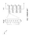
- FIG. 1 illustrates a block diagram of a conventional lead-acid battery pack 100.
- the lead-acid battery pack 100 is generally employed in low cost applications due to its simple structure.
- the lead-acid battery pack 100 can include multiple battery modules 101-104 coupled in series. Each of the battery modules 101-104 can consist of six battery cells 111-116 and two electrodes 120 and 129. Only a voltage of each battery module can be monitored via the two electrodes 120 and 129. Once any of the battery cells 101-106 is damaged, the entire battery pack 100 will be damaged. An unbalance between any two of the battery cells 101-106 can further shorten the lifetime of the lead-acid battery pack 100.
- Embodiments of a battery management system for a battery pack comprising multiple battery modules are disclosed. Each of the battery modules includes multiple battery cells.
- the battery management system includes multiple first balancing units, multiple first controllers, a second balancing unit including multiple second balancing circuits, and a second controller coupled to the battery modules and the second balancing circuits.
- the first controllers are operable for controlling the first balancing units to adjust voltages of battery cells in the battery module if an unbalance occurs between the battery cells.
- the second controller is operable for controlling said second balancing circuits to adjust voltages of said battery modules if an unbalance occurs between battery modules.
- FIG. 1 illustrates a block diagram of a conventional lead-acid battery pack.
- FIG. 2A illustrates a block diagram of a battery management system for a battery pack, in accordance with one embodiment of the present invention.
- FIG. 2B illustrates a structure of a balancing circuit in a battery management system for a battery pack, in accordance with one embodiment of the present invention.
- FIG. 2C illustrates a structure of a balancing unit in a battery management system for a battery pack, in accordance with one embodiment of the present invention.
- FIG. 3 illustrates a block diagram of a battery management system for a battery pack, in accordance with another embodiment of the present invention.
- FIG. 4 illustrates a block diagram of a battery management system for a battery pack, in accordance with another embodiment of the invention.
- FIG. 5 illustrates a structure of a battery pack, in accordance with one embodiment of the present invention.
- FIG. 6 illustrates a flowchart of operations performed by a battery management system for a battery pack, in accordance with one embodiment of the present invention.
- FIG. 7 illustrates a block diagram of elements of an electric vehicle, in accordance with one embodiment of the present invention.
- FIG. 8 illustrates a block diagram of a battery management system for a battery pack, in accordance with another embodiment of the present invention.
- FIG. 9 illustrates a block diagram of a battery management system for a battery pack, in accordance with another embodiment of the present invention.
- FIG. 10 illustrates a flowchart of operations performed by a battery management system for a battery pack, in accordance with one embodiment of the present invention.
- a battery management system for a battery pack can include multiple first controllers to sense voltages of multiple battery cells coupled in series and to control multiple first balancing circuits to adjust the voltages of the battery cells if an unbalance occurs between the battery cells. If an abnormal condition occurs, the first controllers can take measures to protect the corresponding battery cells.
- the battery management system can further include a second controller to sense voltages of multiple battery modules coupled in series and to control multiple second balancing circuits to adjust the voltages of the battery modules if an unbalance occurs between the battery modules. Due to the balancing technology used for the battery cells and the battery modules, the battery cells and/or modules are protected from being damaged. Hence, the economy of the battery management system can be improved and battery lifetime can be extended.
- FIG. 2A illustrates a block diagram of a battery management system 200 for a battery pack, e.g., a lead-acid battery pack, in accordance with one embodiment of the present invention. Balancing technology is used to increase the lifetime of the battery pack and to improve the economy of the battery management system 200.
- a battery pack e.g., a lead-acid battery pack
- the battery pack can include multiple battery modules, e.g., 211-216, coupled in series.
- Each of the battery modules 211-216 can further include multiple battery cells, e.g., 3, 4, 5, or 6 battery cells.
- Each battery cell may have a voltage of, for example, 2 volts, in which case the voltage of each battery module can be 6 volts, 8 volts, 10 volts, or 12 volts, depending on the number of battery cells.
- the battery pack is coupled to a balancing unit 220.
- the balancing unit 220 can include multiple balancing circuits 221-226 coupled to the battery modules 211-216.
- the balancing circuit 221 is coupled to the battery module 211
- the balancing circuit 222 is coupled to the battery module 212, etc.
- the number af the battery cells, the battery modules and the balancing circuits is not limited and can vary based upon the requirements of different applications. For brevity and clarity, an example of 12-volt battery module will be described below in detail.
- a controller 230 is coupled to the battery pack, e.g., the battery modules 211-216, and can monitor parameters, e.g., the voltages and/or the temperatures, of the battery modules 211-216. In one embodiment, the controller 230 can timely sense the voltages of the battery modules 211-216 and then calculate the voltage difference between the battery modules 211-216. The controller 230 can determine if an unbalance occurs based upon the voltage difference. When an unbalance occurs between the battery modules 211-216, the controller 230 can control the corresponding balancing circuits to adjust the voltages of the unbalanced battery modules. In one embodiment, the controller 230 can enforce a threshold V THM to determine if an unbalance occurs.
- the controller 230 can determine that there is an unbalance. Then the controller 230 can initiate the corresponding balancing circuits to control an adjustment of the voltages of the unbalanced battery modules.
- the voltages of the battery modules 211 and 212 sensed by the controller 230 are equal to V M1 and V M2 , e.g., 12.4 volts and 12 volts, respectively. If the voltage difference ⁇ V M12 between the battery modules 211 and 212 is larger than the threshold V THM , e.g., 0.1 volts, the controller 230 can determine that there is an unbalance between the battery modules 211 and 212. Under control of the controller 230, the balancing circuits 221 and 222 can adjust the voltages of the battery modules 211 and 212 to balance the battery modules 211 and 212, e.g., the voltage difference between the battery modules 211 and 212 is not larger than the threshold V THM .
- the balancing circuit 221 in a passive mode, can discharge the battery module 211 during a discharging period or bypass the battery module 211 in a charging period in one or more cycles until ⁇ V M12 is decreased to the threshold V THM .
- the energy of the battery module 211 in an active mode, can be transferred to the battery module 212 via a transformer (not shown) until ⁇ V M12 is decreased to the threshold V THM .
- the controller 230 calculates the voltage differences between those battery modules and prioritizes the voltage differences. For example, a voltage difference with the largest value can be given the highest priority, and a voltage difference with the smallest value can be given the lowest priority. If two or more voltage differences have the same values, these voltage differences can be given the same priority. Then the controller 230 can adjust the unbalanced battery modules according to the priority for thermal control purposes. In such an embodiment, if two or more voltage differences have the same priority, the controller 230 can control the corresponding balancing circuits concurrently to adjust the voltages of the unbalanced battery modules. In another embodiment, if the battery management system 200 has a cooler or fan to solve the thermal problem, the controller 230 will not determine and/or provide the priority of the voltage differences and can adjust all the unbalanced battery modules concurrently.
- an electronic control unit (ECU) 240 is coupled to the controller 230 via the bus 250 and can process data read from the controller 230.
- the data can include, but is not limited to, the voltages and/or the temperatures of the battery modules 211-216.
- the ECU 240 is provided with software control for managing the balancing of the battery pack.
- the ECU 240 can further display the data, and/or send the data to other devices (not shown) for further processing.
- the ECU 240 is optional. In one embodiment, the ECU 240 is omitted for cost-saving purposes.
- the controller 230 can timely monitor the unbalance between the battery modules 211-216 and control the corresponding balancing circuits to adjust the voltages of the unbalanced battery modules.
- the measures mentioned above can be taken to protect the unbalanced battery modules from being damaged.
- the lifetime of the battery pack can be increased.
- FIG. 2B illustrates a structure of a balancing circuit 200B in a battery management system for a battery pack, e.g., a lead-acid battery pack in a passive mode, in accordance with one embodiment of the present invention.
- FIG. 2B is described in combination with FIG. 2A .
- the balancing circuits, e.g., 221-226, in FIG. 2A can employ the structure of the balancing circuit 200B.
- the balancing circuit 200B can include a resistor 281 and a switch 282 coupled in series.
- the balancing circuit 200B can be coupled to one of the battery modules in FIG. 2A . More specifically, a terminal of the resistor 281 can be coupled to a positive terminal of one battery module and a terminal of the switch 282 can be coupled to a negative terminal of the battery module.
- the switch 282 can be controlled by the controller 230.
- a first balancing circuit is coupled to a first battery module, and a second balancing circuit is coupled to a second battery module.
- the voltage of the first battery module is larger than that of the second battery module and there is an unbalance when the voltage difference between the first and second battery modules is larger than a threshold.
- the controller 230 turns on a first switch in the first balancing circuit and turns off a second switch in the second balancing circuit.
- a discharging current can flow through a first resistor in the first balancing circuit, and hence the first balancing circuit can discharge the first battery module until a balance is reached between the first and second battery modules.
- a bypassing current can flow though the first resistor, and consequently the first balancing circuit can bypass the first battery module until a balance is reached between the first and second battery modules.
- FIG. 2C illustrates a structure of a balancing unit 200C in a battery management system for a battery pack, e.g., a lead-acid battery pack in an active mode, in accordance with one embodiment of the present invention.
- the balancing unit 200C can include a transformer.
- FIG. 2C is described in combination with FIG. 2A .
- the balancing unit 200C can act as the balancing unit 220 in place of the balancing circuits 221-226 in FIG. 2A .
- the balancing unit 200C includes multiple secondary windings, e.g., 291-296, coupled to multiple switches 291A-296A in series.
- Each of the secondary windings 291-296 is coupled to a respective battery module, e.g., one of the battery modules 211-216.
- the secondary winding 291 can be coupled to the battery module 211 via the switch 291A and the secondary winding 292 and can be coupled to the battery module 212 via the switch 292A, etc.
- the balancing unit 200C can further include a primary winding 290 coupled to a switch 290A in series.
- the primary winding 290 can be coupled to the battery pack via the switch 290A. All of the switches, e.g., 290A-296A, can be controlled by the controller 230.
- a first secondary winding is coupled to a first battery module via a first switch
- a second secondary winding is coupled to a second battery module via a second switch.
- the voltage of the first battery module is larger than that of the second battery module and there is an unbalance when the voltage difference between the first and second battery modules is larger than a threshold.
- the controller 230 turns on the first switch and turns off other switches and hence the energy of the first battery module is stored on the first secondary winding.
- the controller 230 turns on the second switch and turns off other switches and hence the energy on the first secondary winding is transferred to the second secondary winding.
- the controller 230 turns on the switch 290A and turns off other switches and hence the energy on the first secondary winding is transferred to the primary winding 290.
- the energy on the primary winding 290 can be shared by all of the battery modules 211-216. The processing above can be repeated until a balance is achieved.
- FIG. 3 illustrates a block diagram of a battery management system 300 for a battery pack, e.g., a lead-acid battery pack, in accordance with another embodiment of the present invention. Balancing technology is employed to increase the lifetime of the battery pack and to improve the economy of the battery management system 300.
- a battery pack e.g., a lead-acid battery pack
- the battery pack includes multiple battery modules coupled in series (not shown).
- FIG. 3 illustrates one of the battery modules, e.g., a battery module 310.
- the battery module 310 can further include multiple battery cells, e.g., 301-306.
- the battery cells 301-306 are coupled to a balancing unit 320.
- the balancing unit 320 can include multiple balancing circuits, e.g., 321A-326A, which can employ the structure of the balancing circuit 200B in FIG. 2B .
- the balancing circuits 321A-326A can include a resistor, e.g., 311-316, and a switch, e.g., 321-326, coupled in series.
- the number of the battery cells, the battery modules and the balancing circuits herein is not limited and can vary based upon the requirements of different applications. An example of a 2-volt battery cell will be described below in detail.
- a controller 330 is coupled to the battery module 310, e.g., the battery cells 301-306, and can monitor parameters, e.g., the voltages and/or the temperatures, of the battery cells 301-306. In one embodiment, the controller 330 can timely sense the voltages of the battery cells 301-306 and then calculate the voltage difference between the battery cells 301-306. When an unbalance occurs between the battery cells 301-306, the controller 330 can control the corresponding balancing circuits 321A-326A to adjust the voltages of the unbalanced battery cells. In one embodiment, the controller 330 can enforce a threshold V THC to determine if an unbalance occurs. If the voltage difference of the battery cells 301-306 is larger than the threshold, the controller 330 can determine that there is an unbalance. Then the controller 330 can initiate the corresponding balancing circuits to control an adjustment of the voltages of the unbalanced battery cells.
- the voltages of the battery cells 301 and 302 sensed by the controller 330 are equal to V C1 and V C2 , e.g., 2.1 volts and 2.0 volts, respectively. If the voltage difference ⁇ V C12 between the battery cells 301 and 302 is larger than the threshold V THC , e.g., 0.02 volts, the controller 330 can determine that there is an unbalance between the battery cells 301 and 302.
- the controller 330 can control the balancing circuits 321A and 322A to adjust the voltages of the battery cells 301 and 302 until a balance between the battery cells 301 and 302 is reached, e.g., the voltage difference between the battery cells 301 and 302 is not larger than the threshold V THC .
- the balancing circuit 321A in a passive mode, can discharge the battery cell 301 in a discharging period or bypass the battery cell 301 in a charging period until ⁇ VC12 decreases to the threshold V THC . More specifically, in this condition, the controller 330 can send a control signal to the switch 321 and then the switch 321 is turned on in one or more cycles.
- V C1 can be reduced.
- the controller 330 can turn off the switch 321 to stop the discharging or bypassing of the battery cell 301.
- the controller 330 can calculate the voltage differences between those battery cells and prioritize the voltage differences. Then the controller 330 can adjust the unbalanced battery cells according to the priority for thermal control purposes. If two or more voltage differences have the same priority, the controller 330 can control the corresponding balancing circuits concurrently to adjust the voltages of the unbalanced battery cells. In another embodiment, the controller 330 will not determine and/or provide the priority of the voltage differences and can adjust all the unbalanced battery cells concurrently if the battery management system 300 has a cooler or fan to solve the thermal problem.
- the controller 330 can generate an alert signal, and an electronic control unit (ECU) 340 can read the alert signal via a bus 350.
- the controller 330 can identify an abnormal condition that can include, but is not limited to, an over-voltage (OV) condition, an under-voltage (UV) condition, or an over-temperature (OT) condition.
- an abnormal condition can include, but is not limited to, an over-voltage (OV) condition, an under-voltage (UV) condition, or an over-temperature (OT) condition.
- OV over-voltage
- UV under-voltage
- OT over-temperature
- the controller 330 can control the corresponding balancing circuit to disable the charging of the OV battery cell. If an UV condition occurs, the controller 330 can control the corresponding balancing circuit to disable the discharging of the UV battery cell. If an OT condition occurs, the controller 330 can control the corresponding balancing circuit to reduce the charging or discharging current of the OT battery cell, or even to stop the charging or discharging of the OT battery cell.
- the number of the battery cells with an abnormal condition can vary when the battery management system 300 is in operation. If an abnormal condition occurs to multiple battery cells, the controller 330 can control the corresponding balancing circuits concurrently to further improve the efficiency of the battery management system 300.
- the ECU 340 is coupled to the controller 330 via the bus 350 and can process data read from the controller 330.
- the data can include, but is not limited to, the voltages and/or the temperatures of the battery cells 301-306, and the alert signal indicating an abnormal condition.
- the ECU 340 is provided with software control for the balancing management of the battery pack.
- the ECU 340 can further display the data, and/or send the data to other devices (not shown) for further processing.
- the ECU 340 is optional. In one embodiment, the ECU 340 is omitted for cost-saving purposes.
- the balancing unit 200C can replace all of the balancing circuits including the balancing unit 320, e.g., the balancing circuits 321A-326A, in an active mode.
- a first secondary winding is coupled to a first battery cell via a first switch
- a second secondary winding is coupled to a second battery cell via a second switch.
- the voltage of the first battery cell is larger than that of the second battery cell and there is an unbalance when the voltage difference between the first and second battery cells is larger than a threshold.
- the controller 330 turns on the first switch and turns off other switches and hence the energy of the first battery cell is stored on the first secondary winding.
- the controller 330 turns on the second switch and turns off other switches and hence the energy on the first secondary winding is transferred to the second secondary winding. In another embodiment, the controller 330 turns on the switch 290A and turns off other switches and hence the energy on the first secondary winding is transferred to the primary winding 290.
- the energy on the primary winding 290 can be shared by all of the battery cells 301-306. The processing above can be repeated until a balance is achieved.
- the controller 330 can timely monitor the unbalance between the battery cells 301-306 and control the corresponding balancing circuits to adjust the voltages of the unbalanced battery cells. Hence, the measures mentioned above can be taken to protect the unbalanced battery cells from being damaged.
- the controller 330 can detect an abnormal condition in the battery cells 301-306 and then can take the above-mentioned measures to protect each battery cell and extend the battery lifetime. Consequently, the lifetime of the battery pack can be increased.
- FIG. 4 illustrates a block diagram of a battery management system 400 for a battery pack, e.g., a lead-acid battery pack, in accordance with another embodiment of the invention.
- Balancing technology for battery cells and balancing technology for battery modules are used in the battery management system 400 to extend the lifetime of the battery pack and to facilitate the balancing rate if any unbalance occurs.
- FIG. 4 is described in combination with FIG. 2A , FIG. 2B , FIG. 2C and FIG. 3 .
- the elements in FIG. 4 labeled similar to those in other figures have similar functions.
- the battery pack can include multiple battery modules, e.g., 411-416.
- Each of the battery modules can consist of multiple battery cells coupled in series (not shown in FIG. 4 ).
- An example of the battery module 411 will be described below.
- Each of the battery cells in the battery module 411 is coupled to a respective balancing circuit in a balancing unit 421.
- the balancing unit 421 can employ the structure of the balancing unit 320 in FIG. 3 .
- the balancing unit 421 can employ the structure of the balancing unit 200C in FIG. 2C .
- a controller 431 is coupled to the battery cells in the battery module 411 and can monitor parameters, e.g., the voltages and/or the temperatures, of the battery cells.
- the controller 431 can act as a front-end module.
- the controller 431 can control the corresponding balancing circuit to protect the abnormal battery cell and generate an alert signal to an electronic control unit (ECU) 441 via a bus 491.
- ECU electronice control unit
- the controller 431 can control the corresponding balancing circuits concurrently to protect the corresponding battery cells so as to improve the efficiency of the battery management system 400.
- the controller 431 can timely sense the voltages of the battery cells in the battery module 411. When an unbalance occurs between the battery cells in the battery module 411, the controller 431 can control the corresponding balancing circuits to adjust the voltage of the unbalanced battery cells by discharging or bypassing the corresponding battery cells or transferring energy between the corresponding battery cells.
- the ECU 441 is coupled to the controller 431 via the bus 491 and can process data received from the controller 431.
- the ECU 441 can further display the data.
- the ECU 441 can transfer the data to an ECU 480 via a coupler 451 for further processing.
- the coupler 451 is used to isolate the communication between a low-voltage side, e.g., the ECU 480, and a high-voltage side, e.g., the ECU 441, to protect the ECU 480 from being damaged by the higher voltage.
- the controller 431 can be coupled to a battery cell in other battery modules (not shown), e.g., the first battery cell, in the battery module 412. Hence, the controller 431 can sense the voltages of the first battery cell in the battery module 412 and the battery cells in the battery module 411 concurrently. If an abnormal condition occurs or an unbalance occurs between the first battery cell in the battery module 412 and the battery cells in the battery module 411, the controller 431 can settle this issue using the above-mentioned measures.
- the controller 431 can control the corresponding balancing circuits to adjust the voltages of the unbalanced battery cells according to a priority of the voltage differences between the battery cells for thermal control purposes. In another embodiment, the controller 431 will not determine and/or provide the priority of the voltage differences and can adjust all the unbalanced battery cells concurrently if a cooler or fan is included to solve the thermal problem. If the abnormal condition occurs to multiple battery cells, the controller 431 can take measures as described previously concurrently to protect the corresponding battery cells so as to improve the efficiency of the battery management system 400.
- the controller 470 is coupled to a balancing unit 460, e.g., multiple balancing circuits, e.g., 461-466, and can timely sense the voltages of the battery modules 411-416.
- the balancing circuits 461-466 can employ the structure of the balancing circuit 200B in FIG. 2B and implement similar functions as previously described herein.
- the balancing unit 460 can employ the structure of the balancing unit 200C in FIG. 2C and implement similar functions as previously described herein.
- the controller 470 can control the corresponding balancing circuits 461-466 to adjust the unbalanced battery modules.
- the controller 470 can control the corresponding balancing circuits to adjust the voltages of the unbalanced battery modules according to a priority of the voltage differences between the battery modules for thermal control purposes. In another embodiment, the controller 470 will not determine and/or provide the priority of the voltage differences and can adjust all the unbalanced battery modules concurrently if a cooler or fan is included to solve the thermal problem.
- the ECU 480 is coupled to the controller 470 via a bus 482 and can process data read from the controller 470.
- the ECU 480 can further display the data, and/or send the data to other devices (not shown) for further processing.
- balancing technology for the battery cells and balancing technology for the battery modules are employed to increase the efficiency of the battery management system 400 when an unbalance occurs. Hence, the corresponding battery cells or the corresponding battery modules are protected against damage. Consequently, the lifetime of the battery pack can be expanded.
- the ECUs 441-446, the balancing circuits 461-466, the controller 470, and the ECU 480 included in the battery management system 400 are optional.
- the balancing circuits 461-466 and the controller 470 are omitted and the corresponding functions are implemented by software.
- the ECU 480 can read data from the controllers 431-436 via the ECUs 441-446, and the controllers 431-436 can take the measures described above to solve different issues.
- the bus 482 can be omitted in this condition.
- the ECUs 441-446, the balancing circuits 461-466, the controller 470, and the ECU 480 are omitted, and the controllers 431-436 can take the measures described above to solve different issues.
- FIG. 5 illustrates a battery pack 500, e.g., a lead-acid battery pack, in accordance with one embodiment of the present invention.
- the battery management system 200, 300, or 400 is employed for the battery pack 500.
- the battery pack 500 can include multiple battery modules, e.g., 501-506, coupled in series. Each battery module has two electrodes. The voltage of each of the battery modules 501-506 can be monitored via the two electrodes. For example, the battery module 501 can be monitored via electrodes 530 and 531, and the battery module 506 can be monitored via electrodes 535 and 536.
- each battery module includes multiple battery cells, e.g., 511-516, coupled in series.
- Each battery cell has two electrodes.
- the voltage of each of the battery cells 511-516 can be monitored via the two electrodes.
- the battery cell 511 can be monitored via electrodes 520 and 521, and the battery cell 516 can be monitored via electrodes 525 and 526.
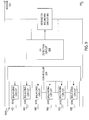
- FIG. 6 illustrates a flowchart 600 of operations performed by a battery management system for a battery pack, in accordance with one embodiment of the present invention.
- FIG. 6 is described in combination with FIG. 4 .
- the controllers 431-436 can monitor parameters, e.g., the voltages and/or temperatures, of the battery cells in the battery modules 411-416.
- the controller 470 can monitor parameters, e.g., the voltages and/or temperatures, of the battery modules 411-416.
- the controllers 431-436 can take certain measures to protect the corresponding battery cells. If an OV condition occurs, the controllers 431-436 can control the corresponding balancing units 421-426 to disable the charging of the OV battery cells. If a UV condition occurs, the controllers 431-436 can control the corresponding balancing units 421-426 to disable the discharging of the UV battery cells. If an OT condition occurs, the controllers 431-436 can control the corresponding balancing units 421-426 to reduce the charging or discharging current of the OT battery cell, or to stop the charging or discharging of the OT battery cell. Advantageously, the controllers 431-436 can control the corresponding balancing units 421-426 concurrently to improve the efficiency of the battery management system 400.
- the controllers 431-436 can calculate the voltage differences between the battery cells, e.g., ⁇ Vc, and compare ⁇ Vc with a threshold V THC . If ⁇ Vc is larger than V THC , an unbalance occurs.
- the controllers 431-436 can control the balancing circuits in the balancing units 411-416 to adjust the voltages of the unbalanced battery cells according to a priority of the voltage differences for thermal control purposes until a balance is achieved.
- the controller 431-436 can adjust the unbalanced battery cells concurrently if a cooler or fan is included to solve the thermal problem.
- the corresponding balancing circuit in a passive mode, can discharge the battery cell with the higher voltage in a discharging period or bypass the battery cell with the higher voltage in a charging period in one or more cycles, until ⁇ Vc is decreased to the threshold V THC .
- the energy of the battery cell with the higher voltage can be transferred to the battery cell with the lower voltage via a transformer (not shown) until ⁇ Vc is decreased to the threshold VT HC .
- the controller 470 can calculate the voltage differences between the battery modules, e.g., ⁇ VM, and compare ⁇ VM with a threshold V THM . If ⁇ V M is larger than V THM , an unbalance occurs. In one embodiment, the controller 470 can control the corresponding balancing circuits 461-466 to adjust the voltages of the unbalanced battery modules according to a priority of the voltage differences for thermal control purposes until a balance is achieved. In another embodiment, the controller 470 can adjust the unbalanced battery modules concurrently if the cooler or fan is included to solve the thermal problem.
- the corresponding balancing circuits can discharge the battery module with the higher voltage in a discharging period, or bypass the battery module with the higher voltage in a charging period, in one or more cycles until ⁇ V M is decreased to the threshold V THM .
- the energy of the battery module with the higher voltage can be transferred to the battery module with the lower voltage via a transformer (not shown) until ⁇ V M is decreased to the threshold V THM .
- balancing technology can be employed to adjust the voltages of multiple battery cells and/or modules according to a priority of the voltage differences or concurrently to improve the efficiency of the battery management system 400.
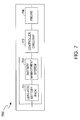
- FIG. 7 illustrates a block diagram of an electric vehicle 700 (e.g., an automobile), in accordance with one embodiment of the present invention.
- FIG. 7 is described in conjunction with the other figures.
- the electric vehicle 700 can include other well-known components in addition to those shown.
- the electric vehicle 700 can include a lead-acid battery pack 701, a battery management system 702, a controller circuitry 703 and an engine 704.
- the lead-acid battery pack 701 is not a limitation; other types of battery pack may be used.
- a battery management system e.g., 200, 300, or 400, can be employed as the battery management system 702.
- the battery management system 702 and the lead-acid battery pack 701 can be integrated into a single integrated circuit (IC).
- the controller circuitry 703 can control the power supply from the lead-acid battery pack 701 to the engine 704.
- the engine 704 can provide energy to the electric vehicle 700.
- the battery management system 702 employs the balancing technology to timely balance multiple battery cells and/or multiple battery modules, and hence the lead-acid battery pack 701 can be protected from being damaged if an unbalance occurs. Hence, the lifetime of the lead-acid battery pack 701 can be increased and the reliability of the electric vehicle 700 can be enhanced.
- FIG. 8 illustrates a block diagram of a battery management system 800 for a battery pack, e.g., a lead-acid battery pack, in accordance with another embodiment of the present invention.
- An inter-cell controller 850 is used to increase the lifetime of the battery pack and reduce the cost of the battery pack.
- FIG. 8 is described with FIG. 2B .
- the battery pack can include one or more battery modules coupled in series.
- the battery pack can include two battery modules 841 and 842 coupled in series.
- Battery module 841 can include six battery cells 801-806
- battery module 842 can include six battery cells 807-812 as illustrated in FIG. 8 .
- Each of the battery cells 801-812 is coupled to a respective balancing circuit.
- each of the balancing circuits 821-832 can employ the structure of the balancing circuit 200B in FIG. 2B . More specifically, a balancing circuit can include a resistor, e.g., 281, and a switch, e.g., 282, coupled in series.
- the number of battery cells, battery modules and balancing circuits herein is not limited and can vary based on the requirements of different applications. An example of 2-volt battery cell will be described below in detail.
- An inter-cell controller 850 is coupled to the balancing circuits 821-832, and the battery cells 801-812 and can monitor parameters, e.g., the voltages, current and/or the temperatures of the battery cells 801-812, control the balancing circuits 821-832 when an unbalanced condition occurs, and further trigger a protection action when an abnormal condition occurs.
- the inter-cell controller 850 can monitor the voltages of the battery cells 801-812, and then can calculate the difference between any two of the battery cells 801-812 in the battery modules 841 and 842. In this situation, the inter-cell controller 850 can determine if an unbalance occurs between any two of the battery cells, even if the battery cells are in different battery modules.
- the inter-cell controller 850 can control the corresponding balancing circuits 821-832 to adjust the voltages of the battery cells.
- the unbalance can be detected by inter-cell controller 850.
- the inter-cell controller 850 can enforce a threshold V TH1 to determine if an unbalance occurs. If a voltage difference between any two cells of the battery cells 801-812 is larger than the threshold V TH1 , the inter-cell controller 850 determines that there is an unbalance.
- the inter-cell controller 850 can initiate the corresponding balancing circuit to control an adjustment of the voltages of the unbalanced battery cells.
- the voltages of the battery cells 801 in the battery module 841 and 807 in the battery module 842 sensed by the inter-cell controller 850 are equal to V 1 and V 2 , e.g., 2.1 volts and 2.0 volts, respectively. If the voltage difference between the battery cells 801 and 807 V 12 is larger than the threshold V TH1 , e.g., 0.02 volts, the inter-cell controller 850 determines that an unbalance occurs between the battery cells 801 and 807. In this condition, the inter-cell controller 850 can control the balancing circuits 821 and 827 until a balance between the battery cells 801 and 807 is reached, e.g.
- the balancing circuit 821 in a passive mode, can discharge the battery cell 801 in a discharging period or bypass the battery cell 801 in a charging period until V 12 decreases to the threshold V TH1 .
- Each of the balancing circuits 821-832 can employ the structure of the balancing circuit in FIG. 2B .
- the inter-cell controller 850 can send a control signal to the switch 282 included in the balancing circuit 821 and the switch 282 in the balancing circuit 821 can be turned on in one or more cycles.
- a discharging current can flow through the resistor 281 and the switch 282 included in the balancing circuit 821.
- V 1 can be reduced.
- a charging current can flow through the resistor 281 and the switch 282 included in the balancing circuit 821.
- the inter-cell controller 850 can calculate the voltage differences between those multiple battery cells and prioritize the voltage differences. In one embodiment, the largest voltage difference can be given the highest priority and the smallest voltage difference can be given the lowest priority and, accordingly, the greater the voltage differences, the higher the priority.
- the inter-cell controller 850 can adjust the unbalanced battery cells according to their respective priority. If two or more voltage differences have the same priority, the inter-cell controller 850 can control the corresponding balancing circuits concurrently to adjust the voltages of the unbalanced cells. In another embodiment, the inter-cell controller 850 will not determine and/or provide the priority of the voltage differences and can adjust all the unbalanced battery cells concurrently if a cooler or fan is included to solve the thermal problem.
- the inter-cell controller 850 can monitor the parameters of each of the battery cells 801-812, e.g. current, voltage and temperature.
- the inter-cell controller 850 can also detect abnormal conditions including, but not limit to an over voltage (OV) condition, an under voltage (UV) condition, an over temperature (OT) condition, a discharge over current (DOC) condition and a charging over current (COC) condition. If an abnormal condition occurs, the inter-cell controller 850 can generate a control signal to turn off a discharge switch 861 in the lead-acid battery pack and/or generate a control signal to turn off a charge switch 862 in the lead-acid battery pack to terminate discharging or charging of the battery cells 801-812.
- OV over voltage
- UV under voltage
- OT over temperature
- DOC discharge over current
- COC charging over current
- the inter-cell controller 850 can monitor the voltages of each of the battery cells 801-812, and compare these voltages with the predetermined thresholds V OV and V UV set by the inter-cell controller 850 and determine if an over voltage condition or an under voltage condition occurs.
- the inter-cell controller 850 can also monitor the voltage of sense resistor 872, and compare the voltage with the predetermined thresholds V COC and V DOC set by the inter-cell controller 850 and determine if a charging over current condition or a discharge over current condition occurs.
- the inter-cell controller 850 can also monitor the voltage of a thermistor (not shown in the Fig.
- the inter-cell controller 850 coupled to each of the cells 801-812 and compare the voltage with a predetermined thresholds V OT set by the inter-cell controller 850 to determine if an over temperature condition occurs. If one of these cell voltages is larger than the predetermined threshold V OV , an over voltage (OV) condition occurs, and the inter-cell controller 850 can generate a control signal to turn off the charge switch 862 to terminate charging of the battery cells 801-812. If one of these cell voltages is less than the predetermined threshold V UV , an under voltage (UV) condition occurs, and the inter-cell controller 850 can generate a control signal to turn off the discharging switch 861 to terminate discharging of the battery cells 801-812.
- V UV over voltage
- the inter-cell controller 850 can generate a control signal to turn off the charging switch 862 to terminate charging of the battery cells 801-812. If the voltage of sense resistor R1 is larger than the predetermined threshold V DOC during a discharging period, a discharge over current (DOC) condition occurs, and the inter-cell controller 850 can generate a control signal to turn off the discharging switch 861 to terminate discharging of the battery cells 801-812.
- DOC discharge over current
- the inter-cell controller 850 can generate a control signal to turn off the discharging switch 861 and/or the charging switch 862 to terminate discharging and/or charging of the battery cells 801-812.
- the inter-cell controller 850 can monitor the unbalance between the battery cells 801-812 in the battery pack, calculate the difference between any two of the battery cells 801-812 even in different battery modules, and control the corresponding balancing circuits to adjust the voltages of the unbalanced battery cells. Furthermore, the inter-cell controller 850 can detect abnormal conditions occurs to the battery cells 801-812 and generate a control signal to turn off the discharge switch 861 and/or the charge switch 862 to terminate discharging and/or charging of the battery cells 801-812 for protecting the battery cells from damaged. Consequently, the battery lifetime of the battery pack can be increased.
- FIG. 9 illustrates a block diagram of a battery management system 900 for a battery pack, e.g., a lead-acid battery pack, in accordance with another embodiment of the invention.
- FIG. 9 is described in combination with FIG. 2B and FIG. 3 .
- the battery pack can include multiple battery modules.
- a battery module including six battery cells 901-906 coupled in series is shown.
- Each of the battery cells 901-906 can be coupled to one of the balancing circuits 921A-926A.
- a controller 930 can be coupled to the battery cells 901-906 and the balancing circuits 921A-926A and can monitor the parameters, e.g., the voltages of the battery cells 901-906.
- Elements that are labeled the same as in FIG. 3 have similar functions and will not be repetitively described herein.
- an over voltage (OV) detection circuit 960 can be coupled to the terminals of the battery module and can monitor the voltage of the battery module in the battery pack.
- the OV detection circuit 960 also can be coupled to a module OV balancing circuit 962 that is coupled to the terminals of the battery module.
- the module OV balancing circuit 962 can employ the structure of the balancing circuit shown in FIG. 2B to reduce the cost of the battery pack. More specifically, the module OV balancing circuit can include a resistor 281 and a switch 282 coupled in series as shown in FIG. 2B .
- the OV detection circuit 960 can monitor the voltage of the battery module and determine if an over voltage condition occurs. More specifically, the OV detection circuit 960 can set a predetermined threshold V THOV , e.g., 14.76V, for a battery module of 12 volts. The OV detection circuit 960 can monitor the voltage of the battery module and compare the detected voltage with the predetermined threshold V THOV , and can determine that an over voltage condition occurs when the detected voltage is greater than the predetermined threshold V THOV . In response to an over voltage condition, the OV detection circuit 960 can generate a control signal to the module OV balancing circuit 962 to switch on the switch 282 included in the module OV balancing circuit 962.
- V THOV e.g. 14.76V
- a bypass path including the switch 282 and the resistor 281 can be established between the terminals of the battery module.
- the module OV balancing circuit 962 can discharge the battery module when the charging mode is terminated, or it can bypass the battery module in a charging mode in one or more cycles until the voltage of the battery module is not greater than the predetermined threshold V THOV .
- the OV detection circuit 960 can be used to monitor a battery module that includes various numbers of battery cells. Accordingly, the predetermined threshold V THOV can be set based on the number of the battery cells in a battery module, e.g., 26V for a battery module including twelve battery cells with battery module voltage of 24 volts. Furthermore, the resistance of the resistor included in the module OV balancing circuit 962 can be set in accordance with the number of the battery cells in the battery module to adjust the bypass current so as to improve the efficiency of the battery management system 900.
- the module OV balancing circuit 962 can adjust the battery module voltage, and the balancing circuits 921A-926A can adjust the voltages of the battery cells in the battery module simultaneously.
- the response rate of the battery management system 900 can be increased, the efficiency of the battery management system 900 can be improved, and the life time of the battery pack can be increased.
- FIG. 10 illustrates a flowchart 1000 of operations performed by a battery management system for a battery pack, e.g., a lead-acid battery pack, in accordance with one embodiment of the present invention.
- FIG. 10 is described in combination with FIG. 9 .
- the controller 930 can monitor parameters, e.g., the voltages of the multiple battery cells 901-906 in the battery module, and the OV detection circuit 960 monitors the voltage of the battery module V M , as illustrated in FIG. 9 .
- the OV detection circuit 960 can determine if an over voltage condition occurs. For example, the OV detection circuit 960 can monitor the battery module voltage V M and compare V M with a predetermined threshold V THMOV . When the battery module voltage V M is greater than the predetermined threshold V THMOV , an over voltage condition is detected. The OV detection circuit 960 can control the module OV balancing circuit 962 to adjust the battery module voltage V M . More specifically, the module OV balancing circuit 962 can discharge or bypass the battery module until the battery module voltage V M is decreased to the predetermined threshold V THMOV .
- the predetermined threshold V THMOV can be set in accordance with the number of the cells in the battery module so that the over voltage condition can be detected regardless of the number of the cells in the battery module, and the resistance of the resistor in the module OV balancing circuit 962 can also be set in accordance with the number of the cells in the battery module, so that the bypass current can be adjusted and the efficiency of the battery management system 900 can be improved.
- the controller 930 can calculate the voltage differences between any two of the multiple battery cells, e.g., V CELL , and compare the voltage difference V CELL with a predetermined threshold V THCELL . When V CELL is larger than the predetermined threshold V THCELL , an unbalanced condition occurs across the multiple battery cells.
- the controller 930 can control the corresponding balancing circuits to adjust the voltages of the unbalanced cells.
- the corresponding balancing circuit can discharge the battery cell with the higher voltage in a discharging period or bypass the battery cell with the higher voltage in a charging period in one or more cycles until the voltage difference V CELL is decreased to the predetermined threshold V THCELL .
- multiple balancing circuits and the module OV balancing circuit can be employed to adjust the voltages of the multiple battery cells and/or modules simultaneously to improve the efficiency of the battery management system 900.
- inventions in accordance with the present invention provide a battery management system for a battery pack such as a lead-acid battery pack.
- the battery management system can include multiple controllers to sense voltages of multiple battery cells coupled in series and to control multiple balancing circuits to adjust the voltages of the battery cells if an unbalance occurs between the battery cells. If an abnormal condition occurs to the battery cells, the controller can take measures to protect the battery cells. Due to the balancing technology, the battery cells are protected against damage. Hence, the efficiency of the battery management system can be improved and battery lifetime can be extended.
- the battery management system can further include a controller to sense voltages of battery modules coupled in series and to control multiple balancing circuits to adjust the voltages of the battery modules if an unbalance occurs between the battery modules. Due to the balancing technology, the battery modules are protected against damage. Hence, the efficiency of the battery management system can be improved and battery lifetime can be extended.
Landscapes
- Engineering & Computer Science (AREA)
- Power Engineering (AREA)
- Life Sciences & Earth Sciences (AREA)
- Sustainable Development (AREA)
- Sustainable Energy (AREA)
- Transportation (AREA)
- Mechanical Engineering (AREA)
- Charge And Discharge Circuits For Batteries Or The Like (AREA)
- Secondary Cells (AREA)
Applications Claiming Priority (2)
| Application Number | Priority Date | Filing Date | Title |
|---|---|---|---|
| CN201010215983.2A CN102299529B (zh) | 2010-06-25 | 2010-06-25 | 电池组管理系统、电动车及管理电池组的方法 |
| US12/850,033 US8198862B2 (en) | 2010-06-25 | 2010-08-04 | Battery pack with balancing management |
Publications (2)
| Publication Number | Publication Date |
|---|---|
| EP2400624A2 true EP2400624A2 (fr) | 2011-12-28 |
| EP2400624A3 EP2400624A3 (fr) | 2014-07-09 |
Family
ID=43878786
Family Applications (1)
| Application Number | Title | Priority Date | Filing Date |
|---|---|---|---|
| EP11167936.1A Withdrawn EP2400624A3 (fr) | 2010-06-25 | 2011-05-27 | Bloc-batteries doté d'une gestion de l'équilibrage |
Country Status (4)
| Country | Link |
|---|---|
| US (2) | US8198862B2 (fr) |
| EP (1) | EP2400624A3 (fr) |
| JP (1) | JP2012010584A (fr) |
| CN (1) | CN102299529B (fr) |
Families Citing this family (72)
| Publication number | Priority date | Publication date | Assignee | Title |
|---|---|---|---|---|
| US9496721B2 (en) * | 2009-10-14 | 2016-11-15 | Ud Trucks Corporation | Power storage apparatus |
| US9099871B2 (en) * | 2010-10-06 | 2015-08-04 | Southwest Electronic Energy Corporation | Module bypass switch for balancing battery pack system modules |
| US9000935B2 (en) * | 2011-03-31 | 2015-04-07 | Elite Power Solutions Llc | Battery management system |
| US9595847B2 (en) | 2010-11-04 | 2017-03-14 | Elite Power Solutions Llc | Uninterrupted lithium battery power supply system |
| GB2486016A (en) * | 2010-12-02 | 2012-06-06 | Sony Corp | Control of storage devices in an electric power network |
| TWI412205B (zh) * | 2011-01-28 | 2013-10-11 | Acbel Polytech Inc | Battery pack potential balance circuit |
| JP5469625B2 (ja) * | 2011-03-01 | 2014-04-16 | 株式会社日立製作所 | 電池システム |
| US9196930B2 (en) * | 2011-03-24 | 2015-11-24 | Ford Global Technologies, Llc | Vehicle battery cell with integral control circuit |
| US10116149B1 (en) | 2011-03-31 | 2018-10-30 | Elite Power Solutions, LLC | Automatic control system for a rechargeable battery system |
| US10358043B2 (en) | 2011-03-31 | 2019-07-23 | Elite Power Solutions, LLC | Golf cart battery system |
| US9553460B2 (en) | 2011-03-31 | 2017-01-24 | Elite Power Solutions Llc | Wireless battery management system |
| US10084334B1 (en) | 2011-03-31 | 2018-09-25 | Elite Power Solutions, LLC | Home energy storage battery system |
| WO2012145319A1 (fr) * | 2011-04-20 | 2012-10-26 | A123 Systems, Inc. | Système et procédé d'équilibrage de charge entre des cellules de batterie |
| DE102011079126B4 (de) * | 2011-07-14 | 2023-02-02 | Robert Bosch Gmbh | Batteriemanagementsystem, Batterie, Kraftfahrzeug mit Batteriemanagementsystem sowie Verfahren zur Überwachung einer Batterie |
| US9559529B1 (en) * | 2011-07-28 | 2017-01-31 | The United States Of America As Represented By The Administrator Of National Aeronautics And Space Administration | Modular battery controller |
| JP5641006B2 (ja) * | 2011-08-31 | 2014-12-17 | ソニー株式会社 | 蓄電装置 |
| DE102011084473B4 (de) * | 2011-10-13 | 2022-06-23 | Vitesco Technologies GmbH | Verfahren zum Symmetrieren von Speicherzellen einer Speichervorrichtung und Speichersystem zum Durchführen des Verfahrens |
| EP2770606B1 (fr) | 2011-10-20 | 2019-04-17 | Hitachi Automotive Systems, Ltd. | Dispositif de surveillance d'un système accumulateur et dispositif de stockage de charge équipé de celui-ci |
| US9401606B2 (en) * | 2011-10-24 | 2016-07-26 | Infineon Technologies Americas Corp. | System and method for providing active power balancing |
| KR20130046234A (ko) * | 2011-10-27 | 2013-05-07 | 삼성에스디아이 주식회사 | 배터리 팩 및 이의 제어 방법 |
| CN102570551A (zh) * | 2012-01-16 | 2012-07-11 | 安徽力高新能源技术有限公司 | 带散热功能的电池组均衡装置 |
| US10180460B1 (en) * | 2012-04-20 | 2019-01-15 | Motiv Power Systems, Inc. | Performing active interrogation of battery packs in situ to obtain precise SOC and SOH estimates |
| FR2993417B1 (fr) * | 2012-07-10 | 2014-07-18 | Batscap Sa | Procede de charge d'une batterie et batterie ainsi chargee |
| US10003062B2 (en) | 2012-09-14 | 2018-06-19 | Lenovo Enterprise Solutions (Singapore) Pte. Ltd. | Modular battery cover |
| US20140097787A1 (en) * | 2012-10-09 | 2014-04-10 | Yi-Ming Lin | Active battery management system for a battery pack |
| CN103023111B (zh) * | 2012-12-14 | 2016-02-10 | 香港生产力促进局 | 一种用于均衡电池组的方法和系统 |
| US10106038B2 (en) | 2012-12-28 | 2018-10-23 | Johnson Controls Technology Company | Dual function battery system and method |
| US9472961B2 (en) | 2013-02-25 | 2016-10-18 | Semiconductor Components Industries, Llc | Method of forming a balancing circuit for a plurality of battery cells and structure therefor |
| US9281696B2 (en) * | 2013-02-27 | 2016-03-08 | Fu-Sheng Tsai | Current steering circuit and current steering method for controlling branch current flowing through branch |
| US8901888B1 (en) | 2013-07-16 | 2014-12-02 | Christopher V. Beckman | Batteries for optimizing output and charge balance with adjustable, exportable and addressable characteristics |
| FR3005535B1 (fr) * | 2013-05-09 | 2016-10-21 | Commissariat Energie Atomique | Systeme de securisation pour module de batterie d'accumulateurs et procede d'equilibrage d'un module de batterie correspondant |
| US9383416B2 (en) | 2013-08-30 | 2016-07-05 | Ford Global Technologies, Llc | System and method for testing vehicle traction battery components |
| US9673658B2 (en) * | 2014-03-06 | 2017-06-06 | Samsung Electro-Mechanics Co., Ltd. | Non-contact capacitive coupling type power charging apparatus and non-contact capacitive coupling type battery apparatus |
| US9583792B2 (en) | 2014-06-11 | 2017-02-28 | Lenovo Enterprise Solutions (Singapore) Pte. Ltd. | Dynamically configurable auto-healing battery |
| US9438048B2 (en) | 2014-06-20 | 2016-09-06 | Lenovo Enterprise Solutions (Singapore) Pte. Ltd. | Modular battery cell architecture and control method |
| US9751427B2 (en) * | 2014-09-03 | 2017-09-05 | Ford Global Technologies, Llc | Vehicle traction battery thermal conditioning |
| US9853471B2 (en) * | 2014-12-16 | 2017-12-26 | Intel Corporation | Mechanism for extending cycle life of a battery |
| US9557387B2 (en) | 2015-02-10 | 2017-01-31 | Lenovo Enterprise Solutions (Singapore) Pte. Ltd. | Testing individual cells within multi-cell battery applications |
| CN105024429A (zh) * | 2015-07-24 | 2015-11-04 | 钟玉麟 | 全时平衡电力系统 |
| JP6821584B2 (ja) * | 2015-10-30 | 2021-01-27 | 三洋電機株式会社 | 蓄電システム |
| KR102559199B1 (ko) | 2015-11-02 | 2023-07-25 | 삼성전자주식회사 | 배터리 관리 방법 및 배터리 관리 장치 |
| CN108702004B (zh) * | 2016-03-01 | 2022-05-03 | 沃尔沃卡车集团 | 用于控制馈送到电池组的电流的方法和系统 |
| US9929571B1 (en) | 2016-03-29 | 2018-03-27 | Elite Power Solutions Llc | Integrated energy storage system |
| CN106100055A (zh) * | 2016-07-26 | 2016-11-09 | 东软集团股份有限公司 | 混合均衡电池管理系统、方法以及车辆 |
| CN106711525B (zh) * | 2017-01-06 | 2019-08-20 | 重庆雅讯电源技术有限公司 | 大规模贮能电池组管理系统及其方法 |
| JP2018117438A (ja) * | 2017-01-17 | 2018-07-26 | 太陽誘電株式会社 | リチウムイオンキャパシタを備えた電源モジュール |
| CN106740241B (zh) * | 2017-03-10 | 2018-07-31 | 吉林大学 | 一种锂电池主动均衡系统 |
| CN107681209B (zh) * | 2017-07-11 | 2019-12-03 | 唐瑭 | 电池状态控制方法、装置、系统及电池组、方法、装置 |
| CN107618376B (zh) * | 2017-08-28 | 2023-08-29 | 山东遥米新能源科技有限公司 | 一种风能锂电池自动均衡系统 |
| KR102202613B1 (ko) * | 2017-09-27 | 2021-01-12 | 주식회사 엘지화학 | 배터리 모듈 균등화 장치, 이를 포함하는 배터리 팩 및 자동차 |
| KR102236384B1 (ko) | 2017-10-27 | 2021-04-05 | 주식회사 엘지화학 | 배터리 밸런싱을 위한 장치 및 그것을 포함하는 배터리팩 |
| US10847835B2 (en) * | 2017-12-13 | 2020-11-24 | William Jeffrey Schlanger | Battery management system for battery banks with a small number of cells |
| US10522881B1 (en) * | 2018-01-12 | 2019-12-31 | Cora Aero Llc | Estimation of self discharge rate as a measure of battery health |
| US11768232B2 (en) * | 2018-01-25 | 2023-09-26 | Volvo Construction Equipment Ab | Equalizer overload management |
| CN112865255A (zh) * | 2018-02-06 | 2021-05-28 | 凹凸电子(武汉)有限公司 | 管理电池组的控制器、系统和方法 |
| KR102361334B1 (ko) * | 2018-05-09 | 2022-02-09 | 주식회사 엘지에너지솔루션 | 배터리 제어 장치 및 이를 포함하는 에너지 저장 시스템 |
| CN108879868A (zh) * | 2018-08-01 | 2018-11-23 | 浙江安美科技有限公司 | 一种电池组分级测控方法及测控系统 |
| US11453309B2 (en) | 2018-09-06 | 2022-09-27 | Artisan Vehicle Systems, Inc. | Electric power distribution system and method for electric mining machine |
| CN111196178A (zh) * | 2018-11-16 | 2020-05-26 | 宁德时代新能源科技股份有限公司 | 转换电路、电池均衡系统及电池管理系统 |
| CN109617161B (zh) * | 2018-12-14 | 2022-04-22 | 西南交通大学 | 一种准谐振交错开关电容电池均衡电路及其控制方法 |
| KR102556994B1 (ko) * | 2019-02-20 | 2023-07-17 | 삼성에스디아이 주식회사 | 셀 밸런싱 제어 방법 및 이를 수행하는 배터리 관리 시스템 |
| JP7096193B2 (ja) * | 2019-04-04 | 2022-07-05 | 矢崎総業株式会社 | 電池制御ユニット及び電池システム |
| WO2020215154A1 (fr) | 2019-04-23 | 2020-10-29 | Dpm Technologies Inc. | Machine électrique rotative tolérante aux défaillances |
| CN113875113B (zh) * | 2019-10-22 | 2024-02-27 | 株式会社Lg新能源 | 用于使并联连接的电池组平衡的装置和方法 |
| US11424492B2 (en) | 2019-10-31 | 2022-08-23 | Sion Power Corporation | System and method for operating a rechargeable electrochemical cell or battery |
| CN112952224B (zh) * | 2019-12-11 | 2022-12-20 | 南京泉峰科技有限公司 | 一种电池包的充电平衡方法、系统和电池包 |
| CN111313117A (zh) * | 2020-03-27 | 2020-06-19 | 华霆(合肥)动力技术有限公司 | 电池模组的无损被动均衡方法、装置和电池系统 |
| CN113547955B (zh) * | 2020-04-23 | 2023-06-16 | 宁德时代新能源科技股份有限公司 | 电池的充电控制方法、装置、电池管理系统和介质 |
| WO2022051308A1 (fr) * | 2020-09-01 | 2022-03-10 | Sion Power Corporation | Système de gestion de batteries multiplexé |
| CA3217299A1 (fr) * | 2021-05-04 | 2022-11-10 | Tung Nguyen | Systemes et procedes de commande de batterie |
| CA3159864A1 (fr) | 2021-05-13 | 2022-11-13 | Exro Technologies Inc. | Methode et appareil d'entrainement des bobines d'une machine electrique multiphasee |
| CN114516283B (zh) * | 2022-03-18 | 2023-10-10 | 中国重汽集团济南动力有限公司 | 一种多冗余车载动力电池系统及控制方法 |
Family Cites Families (25)
| Publication number | Priority date | Publication date | Assignee | Title |
|---|---|---|---|---|
| DE3940928C1 (fr) * | 1989-12-12 | 1991-07-11 | Fraunhofer-Gesellschaft Zur Foerderung Der Angewandten Forschung Ev, 8000 Muenchen, De | |
| US5504415A (en) * | 1993-12-03 | 1996-04-02 | Electronic Power Technology, Inc. | Method and apparatus for automatic equalization of series-connected batteries |
| US6018227A (en) * | 1998-06-22 | 2000-01-25 | Stryker Corporation | Battery charger especially useful with sterilizable, rechargeable battery packs |
| JP2001178008A (ja) * | 1999-12-20 | 2001-06-29 | Nec Corp | セルバランス調整回路、セル電圧異常検出回路、セルバランス調整方法およびセル電圧異常検出方法 |
| JP2001289886A (ja) * | 2000-04-03 | 2001-10-19 | Sanyo Electric Co Ltd | 電池電圧測定装置 |
| US6642693B2 (en) * | 2000-11-21 | 2003-11-04 | Nagano Japan Radio Co., Ltd. | Voltage equalizing apparatus for battery devices |
| JP4605952B2 (ja) * | 2001-08-29 | 2011-01-05 | 株式会社日立製作所 | 蓄電装置及びその制御方法 |
| JP3893291B2 (ja) * | 2002-01-10 | 2007-03-14 | パナソニック・イーブイ・エナジー株式会社 | ハイブリッド車用電池電源装置 |
| US7061207B2 (en) * | 2002-08-09 | 2006-06-13 | H2Eye (International ) Limited | Cell equalizing circuit |
| US7081737B2 (en) * | 2003-06-19 | 2006-07-25 | O2Micro International Limited | Battery cell monitoring and balancing circuit |
| FR2862813B1 (fr) * | 2003-11-20 | 2006-06-02 | Pellenc Sa | Procede de chargement equilibre d'une batterie lithium-ion ou lithium polymere |
| JP4148162B2 (ja) * | 2004-03-05 | 2008-09-10 | 株式会社デンソー | 回路システム |
| US7126312B2 (en) * | 2004-07-28 | 2006-10-24 | Enerdel, Inc. | Method and apparatus for balancing multi-cell lithium battery systems |
| US7508165B2 (en) * | 2004-10-19 | 2009-03-24 | Denso Corporation | Cell voltage equalization apparatus for combined battery pack including circuit driven by power supplied by the combined battery pack |
| US20060087287A1 (en) * | 2004-10-27 | 2006-04-27 | Maxwell Technologies, Inc. | Voltage monitoring for connected electrical energy storage cells |
| JP4186916B2 (ja) * | 2004-11-18 | 2008-11-26 | 株式会社デンソー | 組電池管理装置 |
| KR101188944B1 (ko) * | 2006-06-15 | 2012-10-08 | 한국과학기술원 | 다중 변압기의 2차 권선을 병렬로 연결한 전하 균일 장치 |
| US8461806B2 (en) * | 2007-10-15 | 2013-06-11 | O2Micro Inc | Systems and methods for cell balancing |
| US8030895B2 (en) * | 2007-12-27 | 2011-10-04 | Fenghua Xiao | Cell balancing systems with multiple controllers |
| JP5235481B2 (ja) * | 2008-04-23 | 2013-07-10 | 三洋電機株式会社 | 車両用の電源装置 |
| US7880434B2 (en) * | 2008-05-21 | 2011-02-01 | Southwest Electronic Energy Corporation | System for balancing a plurality of battery pack system modules connected in series |
| JP2010029050A (ja) * | 2008-07-24 | 2010-02-04 | Toshiba Corp | 電池システム |
| US8294421B2 (en) * | 2008-09-05 | 2012-10-23 | O2Micro Inc | Cell balancing systems employing transformers |
| CN101667743B (zh) * | 2008-09-05 | 2012-07-25 | 凹凸电子(武汉)有限公司 | 电池平衡电路、方法以及系统 |
| US8232768B2 (en) * | 2009-01-23 | 2012-07-31 | O2Micro, Inc. | System and method for balancing battery cells |
-
2010
- 2010-06-25 CN CN201010215983.2A patent/CN102299529B/zh active Active
- 2010-08-04 US US12/850,033 patent/US8198862B2/en active Active
- 2010-12-22 US US12/976,501 patent/US8242745B2/en active Active
-
2011
- 2011-05-27 EP EP11167936.1A patent/EP2400624A3/fr not_active Withdrawn
- 2011-05-30 JP JP2011120282A patent/JP2012010584A/ja not_active Withdrawn
Non-Patent Citations (1)
| Title |
|---|
| None |
Also Published As
| Publication number | Publication date |
|---|---|
| US8242745B2 (en) | 2012-08-14 |
| CN102299529A (zh) | 2011-12-28 |
| JP2012010584A (ja) | 2012-01-12 |
| CN102299529B (zh) | 2014-04-02 |
| US8198862B2 (en) | 2012-06-12 |
| US20110140650A1 (en) | 2011-06-16 |
| US20110089897A1 (en) | 2011-04-21 |
| EP2400624A3 (fr) | 2014-07-09 |
Similar Documents
| Publication | Publication Date | Title |
|---|---|---|
| EP2400624A2 (fr) | Bloc-batteries doté d'une gestion de l'équilibrage | |
| US8723481B2 (en) | Battery pack with balancing management | |
| US10044211B2 (en) | Battery pack and method of controlling the same | |
| US8350531B2 (en) | Secondary battery charge control method and charge control circuit | |
| US8796996B2 (en) | Charge control circuit, battery pack, and charge system | |
| JP6955972B2 (ja) | 制御装置、制御システム、蓄電装置及びプログラム | |
| JP5301036B2 (ja) | 車両用の搭載電気系統および搭載電気系統の制御装置 | |
| US20110291619A1 (en) | Battery power source device, and battery power source system | |
| US20080084182A1 (en) | Lithium battery system | |
| KR101262524B1 (ko) | 이차 전지의 과전류 보호 장치, 보호 방법 및 전지 팩 | |
| US20130193926A1 (en) | Battery System and Method for Charging a Large Number of Battery Cells which are Connected in Series | |
| JP2011004509A5 (fr) | ||
| EP2899842A1 (fr) | Bloc-batterie secondaire et procédé d'authentification | |
| WO2017054148A1 (fr) | Structure d'équilibrage d'éléments de batterie | |
| TWI474578B (zh) | 電池組管理系統及平衡電池組中的電池模組的方法 | |
| EP2854254A1 (fr) | Station de chargement avec système d'équilibrage de cellule de batterie | |
| CN103516015A (zh) | 用于为电能存储器充电的方法和装置 | |
| TWI505601B (zh) | 電池組之管理系統、管理方法及其電動車 | |
| KR102196351B1 (ko) | 임베디드 모듈과 pcm을 이용한 배터리 보호장치 | |
| KR20110096430A (ko) | 보조 셀을 사용하여 셀 밸런싱을 하는 방법 | |
| KR101578707B1 (ko) | 배터리 팩 및 이의 제어 방법 | |
| KR20120015861A (ko) | 보조 셀을 사용하여 셀 밸런싱을 하는 방법 | |
| KR20130015651A (ko) | 이차 전지의 과전압 보호 장치, 보호 방법 및 전지 팩 | |
| JPWO2020080543A1 (ja) | 蓄電システム | |
| CN103904708A (zh) | 装设有电池串联充电过充电保护装置的锂电池 |
Legal Events
| Date | Code | Title | Description |
|---|---|---|---|
| AK | Designated contracting states |
Kind code of ref document: A2 Designated state(s): AL AT BE BG CH CY CZ DE DK EE ES FI FR GB GR HR HU IE IS IT LI LT LU LV MC MK MT NL NO PL PT RO RS SE SI SK SM TR |
|
| AX | Request for extension of the european patent |
Extension state: BA ME |
|
| PUAI | Public reference made under article 153(3) epc to a published international application that has entered the european phase |
Free format text: ORIGINAL CODE: 0009012 |
|
| PUAL | Search report despatched |
Free format text: ORIGINAL CODE: 0009013 |
|
| AK | Designated contracting states |
Kind code of ref document: A3 Designated state(s): AL AT BE BG CH CY CZ DE DK EE ES FI FR GB GR HR HU IE IS IT LI LT LU LV MC MK MT NL NO PL PT RO RS SE SI SK SM TR |
|
| AX | Request for extension of the european patent |
Extension state: BA ME |
|
| RIC1 | Information provided on ipc code assigned before grant |
Ipc: H02J 7/00 20060101AFI20140530BHEP |
|
| STAA | Information on the status of an ep patent application or granted ep patent |
Free format text: STATUS: THE APPLICATION IS DEEMED TO BE WITHDRAWN |
|
| 18D | Application deemed to be withdrawn |
Effective date: 20150110 |