EP2399782B1 - Support frame for lateral fastening of attached parts to a side member of a commercial vehicle chassis - Google Patents
Support frame for lateral fastening of attached parts to a side member of a commercial vehicle chassis Download PDFInfo
- Publication number
- EP2399782B1 EP2399782B1 EP11001155.8A EP11001155A EP2399782B1 EP 2399782 B1 EP2399782 B1 EP 2399782B1 EP 11001155 A EP11001155 A EP 11001155A EP 2399782 B1 EP2399782 B1 EP 2399782B1
- Authority
- EP
- European Patent Office
- Prior art keywords
- mounting
- frame
- region
- wall
- support frame
- Prior art date
- Legal status (The legal status is an assumption and is not a legal conclusion. Google has not performed a legal analysis and makes no representation as to the accuracy of the status listed.)
- Active
Links
- 239000000446 fuel Substances 0.000 claims description 10
- 239000002828 fuel tank Substances 0.000 claims description 6
- 238000002360 preparation method Methods 0.000 claims description 5
- 239000000463 material Substances 0.000 claims description 3
- 229910000831 Steel Inorganic materials 0.000 claims description 2
- XSQUKJJJFZCRTK-UHFFFAOYSA-N Urea Chemical compound NC(N)=O XSQUKJJJFZCRTK-UHFFFAOYSA-N 0.000 claims description 2
- 239000004202 carbamide Substances 0.000 claims description 2
- 239000002184 metal Substances 0.000 claims description 2
- 229910001092 metal group alloy Inorganic materials 0.000 claims description 2
- 239000004033 plastic Substances 0.000 claims description 2
- 229920003023 plastic Polymers 0.000 claims description 2
- 239000010959 steel Substances 0.000 claims description 2
- 238000004519 manufacturing process Methods 0.000 description 6
- 239000000969 carrier Substances 0.000 description 3
- 238000010276 construction Methods 0.000 description 3
- 238000009434 installation Methods 0.000 description 3
- 238000005516 engineering process Methods 0.000 description 2
- 239000002816 fuel additive Substances 0.000 description 2
- 238000011031 large-scale manufacturing process Methods 0.000 description 2
- 239000003351 stiffener Substances 0.000 description 2
- 238000005452 bending Methods 0.000 description 1
- 230000001419 dependent effect Effects 0.000 description 1
- 230000009977 dual effect Effects 0.000 description 1
- 230000014759 maintenance of location Effects 0.000 description 1
- 239000007769 metal material Substances 0.000 description 1
- 230000002093 peripheral effect Effects 0.000 description 1
- 230000001012 protector Effects 0.000 description 1
- 230000001105 regulatory effect Effects 0.000 description 1
Images


Classifications
-
- B—PERFORMING OPERATIONS; TRANSPORTING
- B60—VEHICLES IN GENERAL
- B60R—VEHICLES, VEHICLE FITTINGS, OR VEHICLE PARTS, NOT OTHERWISE PROVIDED FOR
- B60R9/00—Supplementary fittings on vehicle exterior for carrying loads, e.g. luggage, sports gear or the like
- B60R9/02—Supplementary fittings on vehicle exterior for carrying loads, e.g. luggage, sports gear or the like at the sides, e.g. on running-board
-
- B—PERFORMING OPERATIONS; TRANSPORTING
- B60—VEHICLES IN GENERAL
- B60K—ARRANGEMENT OR MOUNTING OF PROPULSION UNITS OR OF TRANSMISSIONS IN VEHICLES; ARRANGEMENT OR MOUNTING OF PLURAL DIVERSE PRIME-MOVERS IN VEHICLES; AUXILIARY DRIVES FOR VEHICLES; INSTRUMENTATION OR DASHBOARDS FOR VEHICLES; ARRANGEMENTS IN CONNECTION WITH COOLING, AIR INTAKE, GAS EXHAUST OR FUEL SUPPLY OF PROPULSION UNITS IN VEHICLES
- B60K15/00—Arrangement in connection with fuel supply of combustion engines or other fuel consuming energy converters, e.g. fuel cells; Mounting or construction of fuel tanks
- B60K15/03—Fuel tanks
- B60K15/063—Arrangement of tanks
- B60K15/067—Mounting of tanks
-
- B—PERFORMING OPERATIONS; TRANSPORTING
- B60—VEHICLES IN GENERAL
- B60Y—INDEXING SCHEME RELATING TO ASPECTS CROSS-CUTTING VEHICLE TECHNOLOGY
- B60Y2200/00—Type of vehicle
- B60Y2200/10—Road Vehicles
- B60Y2200/14—Trucks; Load vehicles, Busses
Definitions
- the invention relates to a support frame for the lateral attachment of attachments to a longitudinal member of a commercial vehicle support structure according to the preamble of claim 1.
- a structure is from the document EP 1624 505 A1 known.
- Such support frames are basically known, for example from the DE 10 2004 055 570 A1 comprising a support structure for receiving a modular emission control system.
- the brake device carrier is composed of two cup-shaped holding plates and two carriers for receiving compressed air containers, which are held by straps on the carriers. Each of the two carriers is attached to one of the cup-shaped retaining plates.
- a carrier system for commercial vehicles which has a holder consisting of two halves, the first half is fixed to the outside of a vertical web of a longitudinal member adjacent by means of fastening means and the second holder half with an approximately U-shaped profile section a horizontally projecting from the web of the longitudinal member lower Flange positively engages around the flange.
- a holder for accessories to truck chassis frame is also from the DE 18 89 305 U known.
- a support frame is provided for the lateral attachment of attachments to a longitudinal member of a commercial vehicle support structure having a frame frame.
- the support frame comprises a plurality of frame frame holding elements which are spaced apart from one another in the longitudinal beam extension direction and which are connectable or connected directly or indirectly to the side member and between which a frame frame support region protruding laterally from the side member is formed for at least one support region attachment.
- at least one mounting wall is arranged on the frame frame, which has at least one mounting preparation for mounting at least one additional and a mounting wall attachment-forming attachment.
- the at least one mounting wall may be flat or plate-like or cage-like.
- the at least one planar or plate-like mounting wall preferably runs essentially in the vehicle transverse direction. Vehicle transverse direction is understood to mean a direction which is perpendicular to the longitudinal member extension direction.
- Such a frame-side mounting wall allows advantageously adapted to the particular application assembly of the support frame with the desired components, which is ensured by the mounting preparation on the mounting wall, that the mounting wall attachments can be mounted quickly and reliable.
- Particularly preferred in this case is a construction in which at least part of the mounting wall attachment parts supported on the mounting wall is at least partially covered and / or encapsulated with one or at least one shell-like cover element.
- a shell-like cover can thus protect particularly sensitive components, such as control units or the like reliably against damage in rough driving.
- Such a shell-like cover member thus preferably also forms a part of the support frame and can be adapted to the corresponding respective assembly wishes.
- the shell-like cover element is at least partially formed by a fender wall area also connected to the frame frame.
- the fender is then used in an advantageous dual function at the same time to provide at least a portion of the cover required for covering the attachments, whereby the component cost significantly reduced and a total manufacturing technology compact and inexpensive construction is provided.
- a cover element fender wall region is supported and connected to a free fender end on the frame frame support region, for example folded at the edge and attached to this frame flange support region in a planar abutment connection. This results in a functionally reliable connection of the fender wall region on the support frame, which withstands high loads.
- the cover element fender wall area is spaced and preferably runs approximately parallel to the mounting wall, wherein at least one mounting wall attachment is accommodated in the free space between mounting wall and cover element fender wall area.
- This clearance may then additionally or alternatively, based on the vehicle vertical axis direction, be closed from above with a roof element which is connected to the cover element fender wall region and / or on the mounting wall or is also formed integrally with at least one of these two components.
- This roof element can be formed, for example, by a substantially flat plate, which in turn can itself be a supporting element for a further roof element attachment.
- a support frame which is highly integrated and allows a multifunctional assembly with relatively low component and manufacturing costs.
- a significant advantage of the support frame according to the invention is further that the support frame can be pre-assembled with all attachments before final assembly in the context of a large-scale production, for example, so that the support frame can be mounted together with its attachments as part of the final assembly on the side rail. This considerably reduces the production times and set-up times during final assembly.
- connection of a fender wall area to the frame frame in connection with the optional connection of a fender wall area to the frame frame, the particularly preferred variant has been explicitly described in which this fender wall area simultaneously at least partially a shell-like cover element or a wall region of such a cover element, by means of which the mounting wall attachments can be surrounded or covered like a box, forms. It should be expressly mentioned at this point, however, that the connection of at least one wing of the vehicle body to the frame frame in the present case is also claimed independently of the provision of a mounting wall.
- connection of the fender or at least one fender on the frame manufacturing and set-up times in the final assembly of large-scale production of commercial vehicles can be significantly reduced, which also implement a highly integrated and less complex component solution and can be realized.
- the inventive idea thus allows a support frame structure with a preferably flat mounting wall without connection of a fender.
- the invention allows a support frame structure with a preferably flat mounting wall with connection of a fender and finally a support frame structure without flat mounting wall with connection of a fender.
- the mounting wall preferably rectangular in shape, itself may, for example, have one or more recesses, in which a correspondingly assigned or adapted attachment is accommodated and held in a space-saving or space-saving manner.
- a fuel filter which is at least partially received in a recess of the mounting wall.
- recesses may be provided to thereby allow a targeted passage and optionally also fixation or retention of lines or the like.
- the mounting wall preferably has a substantially rectangular outer contour, which additionally or alternatively extends substantially over the entire width and height of the support frame, so that a large connection surface is provided for connecting a plurality or for connecting large components.
- a control device and / or a boiler of a tire inflation pressure system or a tire pressure regulating system will be supported on the mounting wall.
- a fuel additive pump and / or a cab tilt pump will also be supported on the mounting wall.
- the mounting wall is preferably supported on the frame-frame support region and / or by means of a mounting frame fastening element forming a frame-frame holding element, on which the mounting wall is fixed non-positively and / or positively and / or cohesively on the longitudinal member.
- the mounting wall fastening element is preferably formed by a U-shaped mounting bracket, which is connected to an upper longitudinal beam area, in particular to an upper longitudinal beam side flange area, with an upper U-bracket end area in or relative to the vehicle vertical axis direction with respect to the vertical axis of the vehicle lower U-bar end portion directly on a lower side rail area, in particular on a lower side member side flange, or indirectly, with the interposition of an adapter element is connected to the side rail.
- a U-shaped mounting bracket results in a particularly stable and firm connection of the mounting wall to the frame frame or the side rail, wherein the mounting wall together with its mounting bracket then simultaneously forms a support member for the frame on the side rail.
- the frame-frame support region itself is preferably formed by a plurality of spaced apart and substantially parallel to the longitudinal member extending frame parts. Also, at least part of the retaining elements is preferably formed by a plurality of such strut-like frame parts, in particular such that for a high support width in the vehicle vertical axis direction, a first frame part is connected to an upper side rail portion and a second frame part to a lower side frame member.
- the second frame part extends approximately horizontally, ie in the plane which is formed by the longitudinal members, and essentially forms part of the frame frame support region or is connected to its components, in particular frame parts, while the first frame part facing away from the longitudinal member End is also connected in the region of the frame frame support region, in particular there in the region of a abstütz Scheme rock member and / or in the region of the free end of the second, horizontally extending frame part is connected.
- the mounting wall may be formed, for example, by a production technology easily manufacturable, for example, in cross-section U-shaped steel sheet or a plastic material, while the remaining supporting components of the frame frame are preferably formed at least in part by hollow profile cross-sections of metal or metal alloys.
- the support region attachment is formed by at least one container or a container, preferably by at least one large-volume container, for example or in particular a storage compartment and / or a fuel tank or a urea container.
- at least one large-volume container for example or in particular a storage compartment and / or a fuel tank or a urea container.
- the support frame may be formed by a pre-assembly module.
- the pre-assembly module can be equipped with the attachments before mounting the frame on the side member. This results, for example, a further increased efficiency of the support frame and its handling.
- Fig. 1a is shown schematically and by way of example a side view of an inventive support frame 1, which is laterally connected to a side member 2 of a not shown here in detail and two such, parallel longitudinal member 1 having commercial vehicle support structure.
- the support frame 1 consists of a frame frame 3, which, as in particular from the Fig. 1b to 1d can be seen, a first holding element 4, which, as shown in particular from Fig. 1d can be seen, is formed by a first frame part 5, which preferably has a pipe cross-section.
- This first frame part 5 is connected to an end portion facing the longitudinal member 2, which is formed bent or angled, connected to one, based on the vertical axis of the vehicle upper flange 6 of the longitudinal support 2 also formed here by a hollow profile, for example by means of one or more screw.
- a second frame part 7 of the retaining element 4 is connected to a lower end of the longitudinal member 2, namely indirectly with the interposition of an adapter element 8, for example, on the longitudinal member 2 in a cohesive or frictionally connected manner.
- the connection takes place, for example by means of one or more screw connections.
- the second frame part 7 is angled or bent in the connection region on the adapter element 8, so that this rests on the adapter element 8, as well as the first frame member 5 on the upper flange 6 in a flat contact connection, resulting in a particularly stable connection of the two frame parts 5, 7 allows on the side rail 2.
- the second frame part 7 runs approximately horizontally and is, for example, materially bonded by means of only two spaced-apart support area frame parts 9, 10 extending essentially parallel to one another and to the side member 2, for example connected, which form a frame support area 11 for example, a fuel tank 12 described in more detail below.
- the upper, first frame part extends from the connection region on the upper flange portion 6, starting down to the in the image plane of the Fig. 1d right support area frame part 10 and is connected there for example cohesively.
- the holding element 13 is formed by a mounting wall 14, which in particular also from Fig. 1c it can be seen that a section along the line AA of Fig. 1b shows.
- This mounting wall 14 of, for example, a sheet metal material has a substantially rectangular and substantially over the entire support frame height or width extending outer contour, the recesses 15 and attachment points 16 in defined areas as mounting preparation for a defined installation or for a defined cultivation of attachments, which will be described in more detail below.
- the mounting wall 14 is, which in particular also from the Fig. 1a and the Fig. 1e . 1f . 1g . 1h emerges, on the one hand fixed to the support area frame parts 9, 10, for example screwed there and / or cohesively connected.
- the mounting wall 14 also, for example non-positively by means of screws or alternatively and additionally cohesively, connected to a U-shaped mounting bracket 17, to which the mounting wall 14 preferably rests on this mounting bracket in a planar contact connection.
- This mounting bracket 17 then surrounds the longitudinal member 2 with a top U-bracket end region 18 in the direction of vertical axis of the vehicle and is connected to a folded abutment region in a planar abutment connection on the upper flange section 6, preferably screwed by means of a plurality of force-locking screw connections.
- the mounting bracket 17 is in turn indirectly connected via an adapter element 8, analogous to the second frame part 7 of the support member 4, at the bottom of the longitudinal member 2.
- the lower U-bracket end area 19 is preferably formed, for example, bent or angled formed that a flat abutment connection takes place on the adapter element 8.
- Fig. 1e to 1g are on the flat mounting wall 14 and the local installation preparations set several attachments, such as a boiler 20 and a controller 21 of a tire pressure control system. Further, a fuel additive pump 22 and a cab tilting pump 23 is fixed to the mounting wall 14. The determination is preferably carried out by means of a screw connection.
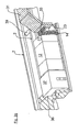
- a view corresponding to the arrow A of Fig. 1e shows, in the region of the recess 15 further comprises a fuel filter 24 is arranged.
- a fuel filter 24 is arranged in the region of the mounting wall 14 in the region of the mounting wall 14 also an edge bend 25 can be provided which has at least one, but preferably a plurality of mounting holes 26, through the lines, here by way of example a fuel line 27, can be passed. Due to the defined design and position of the mounting holes 26, such lines can thus be guided and supported particularly advantageously in the region of the frame frame 3.
- the flat mounting wall 14 can be further stiffened by at least one stiffening element 28.
- These stiffening elements which are formed for example by stiffening plates, preferably extend substantially downwardly from an upper end region of the mounting wall 14 (viewed in the vertical direction of the vehicle) and are supported, for example, in the region of the supporting region frame parts 9, 10 or at the peripheral bend 25 from.
- the stiffener may also be integrally formed on the mounting wall 14 or else, as shown by the two other stiffening elements 28, be formed by separate components.
- the frame-frame support area 11 is formed, in which, substantially "positively," the fuel tank 12 is received and mounted.
- a shell-like cover member which here exemplified by a cover plate 29 is, covered or encapsulated, whereby these components are shielded from the environment.
- the cover plate 29 is likewise fastened to the mounting wall 14 or in the region of the frame-frame support region 11.
- Fig. 1 In this embodiment of the Fig. 1 is thus on the support frame 1, unlike that described in the following Fig. 2 the case is, no fender tied. Rather, here is the fender 31 'spaced from the mounting wall side frame structure arranged (distance a), which in the Fig. 1b only shown extremely schematically. In the space between fender 31 'and support frame 1 or mounting wall 14 can then be arranged, for example, according to a particularly preferred embodiment, not shown here support, for example, a hydraulic support, the vehicle body. This support clearance is designated here by the reference numeral 31 ", the fender 31 'here being preferably connected to the side member 2.
- FIG. 2f another alternative embodiment is shown, in which the cover for covering the mounting wall attachment parts is formed in part by a fender wall portion 30 of a means of this fender wall portion 30 also connected to the frame frame 3 fender.
- the fender wall portion 30 at the free end of the fender here an exemplary bent or beveled trained Koterielanitatis Society 32 which rests on the frame frame support portion 11, in particular on a there beyond the mounting wall 14 also extended support area frame part 9, 10 and with this in a flat system connection is connected.
- the fender wall portion 30 then extends substantially parallel and spaced from the mounting wall 14 in the vehicle vertical axis direction upward, before it is then bent or bent.
- a roof plate 33 is provided, for example, of a sheet material, which is connected both to the fender wall portion 30 and to the mounting wall 14 is, for example by means of a frictional screw 34 shown here only extremely schematically.
- the screw 34 is shown here for the roof panel 33 only in the area of the fender wall portion 30, but may be formed on the side of the mounting wall as well.
- Fig. 2f can be further removed, in the area above the roof panel 33 here another mounting space 35 is formed in which then, for example, in turn, as previously a boiler 20 of a tire pressure control system can be mounted.
- Fig. 2f can also be found that in connection with the connection of a fender 31 on the frame frame 3 and the support frame 1, the mounting wall 14 does not necessarily have to be connected via a mounting bracket 17 on the longitudinal member 2 and thus not necessarily form a holding element corresponding to the holding element 13 , Rather, here, as shown only very schematically by the partially hidden by the fender wall portion 30 first frame part 5, also on this montagewand solution side of the support frame 1, a connection to the side member 2 by means of the holding element 4 corresponding identical structure.
- FIG. 2g an embodiment is shown in which on the right in the image plane, the connection of the wing 31 in the manner just described and at the same time on the side opposite the longitudinal beam extension direction and thus in the vehicle longitudinal direction side of the support frame 1, another fender 36 on the frame 3 is connected.
- the frame frame support region and thus the support frame 1 extends between two fenders 31, 36 and thus has a large support width.
- another functional part 37 for example a storage compartment or the like, can then be held on the frame frame 3.
- FIG. 2a and 2i This basically different structure, as he just in the Fig. 2f and 2g has been described is again - without attachments - in the Fig. 2a to 2e shown in detail.
- the mounting wall 14 is not supported here by means of a mounting bracket 17 on the side rail 2 and thus forms a holding element, but in principle may be the case. Rather, here is the mounting wall 14 so on, based on the image plane of Fig. 2a and 2b right edge and so on moved there the holding member 4 that in between a space for connection of the attachments to the mounting wall 14 is provided and at the same time where appropriate also integrates a fender wall portion 30 and can be connected to the frame frame 3, as has been previously described.
- a further frame part 38 which in turn, like the previously described frame parts 9, 10 and 5, 7 may be formed by a hollow profile, at the upper flange portion 6 and here exemplified on the longitudinal beam 2 facing inner Abstweil Scheme frame part 9 connected.
Description
Die Erfindung betrifft ein Traggestell zur seitlichen Befestigung von Anbauteilen an einem Längsträger einer Nutzfahrzeug-Tragstruktur nach dem Oberbegriff des Anspruchs 1. Eine solche Struktur ist aus dem Dokument
Derartige Traggestelle sind grundsätzlich bekannt, so zum Beispiel aus der
Weiter ist aus der
Auch aus der
Ein Halter für Zubehör an LKW-Fahrgestellrahmen ist ferner auch aus der
Demgegenüber ist es Aufgabe der vorliegenden Erfindung, ein Traggestell zur seitlichen Befestigung von Anbauteilen an einem Längsträger einer Nutzfahrzeug-Tragstruktur dergestalt weiter zu optimieren, dass eine für vielfältigste Einsatzfälle geeignete Tragstruktur für eine multifunktionale Bestückung des Traggestelles zur Verfügung gestellt wird.In contrast, it is an object of the present invention to further optimize a support frame for the lateral attachment of attachments to a side rail of a commercial vehicle support structure such that a suitable for a variety of applications support structure for a multi-functional assembly of the support frame is provided.
Diese Aufgabe wird gelöst mit den Merkmalen des Patentanspruchs 1. Vorteilhafte Ausgestaltungen hierzu sind Gegenstand der Unteransprüche.This object is achieved with the features of claim 1. Advantageous embodiments thereof are the subject of the dependent claims.
Gemäß Anspruch 1 ist ein Traggestell zur seitlichen Befestigung von Anbauteilen an einem Längsträger einer Nutzfahrzeug-Tragstruktur vorgesehen, das einen Gestellrahmen aufweist. Das Traggestell umfasst mehrere, voneinander in Längsträgererstreckungsrichtung beabstandete Gestellrahmen-Halteelemente, die mittelbar oder unmittelbar am Längsträger anbindbar oder angebunden sind und zwischen denen ein seitlich vom Längsträger wegragender Gestellrahmen-Abstützbereich für wenigstens ein Abstützbereich-Anbauteil ausgebildet ist. Weiter ist am Gestellrahmen wenigstens eine Montagewand angeordnet, die wenigstens eine Montagevorbereitung zum Anbau wenigstens eines zusätzlichen und ein Montagewand-Anbauteil ausbildenden Anbauteils aufweist. Die wenigstens eine Montagewand kann flächig oder plattenartig oder käfigartig sein. Die wenigstens eine flächige oder plattenartige Montagewand verläuft vorzugsweise im Wesentlichen in Fahrzeugquerrichtung. Unter Fahrzeugquerrichtung wird eine Richtung verstanden, die senkrecht zur Längsträgererstreckungsrichtung ist.According to claim 1, a support frame is provided for the lateral attachment of attachments to a longitudinal member of a commercial vehicle support structure having a frame frame. The support frame comprises a plurality of frame frame holding elements which are spaced apart from one another in the longitudinal beam extension direction and which are connectable or connected directly or indirectly to the side member and between which a frame frame support region protruding laterally from the side member is formed for at least one support region attachment. Further, at least one mounting wall is arranged on the frame frame, which has at least one mounting preparation for mounting at least one additional and a mounting wall attachment-forming attachment. The at least one mounting wall may be flat or plate-like or cage-like. The at least one planar or plate-like mounting wall preferably runs essentially in the vehicle transverse direction. Vehicle transverse direction is understood to mean a direction which is perpendicular to the longitudinal member extension direction.
Eine derartige gestellseitige Montagewand ermöglicht auf vorteilhafte Weise eine auf den jeweiligen Einsatzfall angepasste Bestückung des Traggestells mit den gewünschten Bauteilen, wobei durch die Montagevorbereitung an der Montagewand sichergestellt ist, dass die Montagewand-Anbauteile schnell und funktionssicher montiert werden können.Such a frame-side mounting wall allows advantageously adapted to the particular application assembly of the support frame with the desired components, which is ensured by the mounting preparation on the mounting wall, that the mounting wall attachments can be mounted quickly and reliable.
Besonders bevorzugt ist hierbei ein Aufbau, bei dem wenigstens ein Teil der an der Montagewand gehalterten Montagewand-Anbauteile wenigstens bereichsweise mit einem oder zumindest einem schalenartigen Abdeckelement abgedeckt und/oder abgekapselt ist. Ein derartiges schalenartiges Abdeckelement kann somit besonders empfindliche Bauteile, wie beispielsweise Steuergeräte oder dergleichen zuverlässig vor Beschädigungen im rauen Fahrbetrieb schützen. Ein derartiges schalenartiges Abdeckelement bildet somit bevorzugt ebenfalls einen Bestandteil des Traggestells und kann den entsprechenden jeweiligen Bestückungswünschen angepasst ausgebildet sein.Particularly preferred in this case is a construction in which at least part of the mounting wall attachment parts supported on the mounting wall is at least partially covered and / or encapsulated with one or at least one shell-like cover element. Such a shell-like cover can thus protect particularly sensitive components, such as control units or the like reliably against damage in rough driving. Such a shell-like cover member thus preferably also forms a part of the support frame and can be adapted to the corresponding respective assembly wishes.
Besonders bevorzugt ist hierbei eine Ausgestaltung, bei der das schalenartige Abdeckelement wenigstens zum Teil durch einen ebenfalls am Gestellrahmen angebundenen Kotflügelwandbereich gebildet ist. Hierbei wird dann somit der Kotflügel in einer vorteilhaften Doppelfunktion gleichzeitig dazu verwendet, wenigstens einen Teil der zur Abdeckung der Anbauteile erforderlichen Abdeckung bereitzustellen, wodurch der Bauteilaufwand wesentlich reduziert und ein insgesamt fertigungstechnisch kompakter und preiswerter Aufbau zur Verfügung gestellt wird.Particularly preferred in this case is an embodiment in which the shell-like cover element is at least partially formed by a fender wall area also connected to the frame frame. In this case, the fender is then used in an advantageous dual function at the same time to provide at least a portion of the cover required for covering the attachments, whereby the component cost significantly reduced and a total manufacturing technology compact and inexpensive construction is provided.
Gemäß einer hierzu konkreten Ausgestaltung kann vorgesehen sein, dass ein Abdeckelement-Kotflügelwandbereich mit einem freien Kotflügelende am Gestellrahmen-Abstützbereich abgestützt und angebunden ist, zum Beispiel randseitig abgekantet ist und mit diesem abgekanteten Flanschbereich in einer flächigen Anlageverbindung am Gestellrahmen-Abstützbereich angebunden ist. Dadurch ergibt sich eine funktionssichere Anbindung des Kotflügelwandbereichs am Traggestell, die hohen Belastungen Stand hält.According to a specific embodiment for this purpose, it can be provided that a cover element fender wall region is supported and connected to a free fender end on the frame frame support region, for example folded at the edge and attached to this frame flange support region in a planar abutment connection. This results in a functionally reliable connection of the fender wall region on the support frame, which withstands high loads.
Gemäß einer hierzu zusätzlichen oder alternativen weiteren bevorzugten Ausgestaltung ist vorgesehen, dass der Abdeckelement-Kotflügelwandbereich beabstandet und vorzugsweise in etwa parallel zur Montagewand verläuft, wobei im Freiraum zwischen Montagewand und Abdeckelement-Kotflügelwandbereich wenigstens ein Montagewand-Anbauteil aufgenommen ist. Dieser Freiraum kann dann zusätzlich oder alternativ, bezogen auf die Fahrzeughochachsenrichtung, von oben her mit einem Dachelement verschlossen sein, das am Abdeckelement-Kotflügelwandbereich und/oder an der Montagewand angebunden ist oder aber auch integral mit wenigstens einem dieser beiden Bauteile ausgebildet ist. Dieses Dachelement kann zum Beispiel durch eine im Wesentlichen ebene Platte gebildet sein, die dann selbst auch wiederum Tragelement für ein weiteres Dachelement-Anbauteil sein kann.According to an additional or alternative further preferred embodiment, it is provided that the cover element fender wall area is spaced and preferably runs approximately parallel to the mounting wall, wherein at least one mounting wall attachment is accommodated in the free space between mounting wall and cover element fender wall area. This clearance may then additionally or alternatively, based on the vehicle vertical axis direction, be closed from above with a roof element which is connected to the cover element fender wall region and / or on the mounting wall or is also formed integrally with at least one of these two components. This roof element can be formed, for example, by a substantially flat plate, which in turn can itself be a supporting element for a further roof element attachment.
Wie die zuvor gemachten Ausgestaltungen zeigen, ergibt sich mit den erfindungsgemäßen Ausführungsformen ein Traggestell, das hochintegrativ ist und eine multifunktionale Bestückung mit relativ geringem Bauteil- und Fertigungsaufwand ermöglicht. Ein wesentlicher Vorteil des erfindungsgemäßen Traggestelles ist dabei ferner, dass das Traggestell mit sämtlichen Anbauteilen bereits vor der Endmontage im Rahmen einer zum Beispiel Großserienfertigung vormontiert werden kann, so dass das Traggestell mitsamt seinen Anbauteilen im Rahmen der Endmontage als Ganzes am Längsträger montiert werden kann. Dadurch werden die Fertigungszeiten und die Rüstzeiten im Rahmen der Endmontage erheblich reduziert.As the embodiments made above show, with the embodiments according to the invention a support frame, which is highly integrated and allows a multifunctional assembly with relatively low component and manufacturing costs. A significant advantage of the support frame according to the invention is further that the support frame can be pre-assembled with all attachments before final assembly in the context of a large-scale production, for example, so that the support frame can be mounted together with its attachments as part of the final assembly on the side rail. This considerably reduces the production times and set-up times during final assembly.
In den zuvor gemachten Ausführungen wurde in Verbindung mit der optionalen Anbindung eines Kotflügel-Wandbereichs am Gestellrahmen explizit die besonders bevorzugte Variante beschrieben, bei der dieser Kotflügel-Wandbereich gleichzeitig wenigstens zum Teil ein schalenartiges Abdeckelement bzw. einen Wandbereich eines solchen Abdeckelementes, mittels dem die Montagewand-Anbauteile gehäuseartig umgriffen bzw. abgedeckt werden können, ausbildet. An dieser Stelle sei jedoch ausdrücklich erwähnt, dass die Anbindung wenigstens eines Kotflügels der Fahrzeugkarosserie am Gestellrahmen vorliegend auch unabhängig von dem Vorsehen einer Montagewand beansprucht wird. Wie bereits zuvor geschildert, können mit einer derartigen Anbindung der Kotflügel bzw. wenigstens eines Kotflügels am Gestellrahmen Fertigungs- und Rüstzeiten im Rahmen der Endmontage der Großserienfertigung von Nutzfahrzeugen erheblich reduziert werden, wobei sich zudem eine hochintegrative und wenig bauteilaufwändige Lösung umsetzen und realisieren lässt.In the above explanations, in connection with the optional connection of a fender wall area to the frame frame, the particularly preferred variant has been explicitly described in which this fender wall area simultaneously at least partially a shell-like cover element or a wall region of such a cover element, by means of which the mounting wall attachments can be surrounded or covered like a box, forms. It should be expressly mentioned at this point, however, that the connection of at least one wing of the vehicle body to the frame frame in the present case is also claimed independently of the provision of a mounting wall. As already described above, with such a connection of the fender or at least one fender on the frame manufacturing and set-up times in the final assembly of large-scale production of commercial vehicles can be significantly reduced, which also implement a highly integrated and less complex component solution and can be realized.
Insgesamt gesehen erlaubt die Erfindungsidee somit einen Traggestellaufbau mit einer vorzugsweise flächigen Montagewand ohne Anbindung eines Kotflügels. Weiter ermöglicht die Erfindungsidee einen Traggestellaufbau mit einer vorzugsweise flächigen Montagewand mit Anbindung eines Kotflügels sowie schließlich einen Traggestellaufbau ohne flächige Montagewand mit Anbindung eines Kotflügels. Diese zusammenfassende Darstellung belegt nochmals die Variabilität und hohe Funktionalität der vorliegenden Erfindungsidee.Overall, the inventive idea thus allows a support frame structure with a preferably flat mounting wall without connection of a fender. Next, the invention allows a support frame structure with a preferably flat mounting wall with connection of a fender and finally a support frame structure without flat mounting wall with connection of a fender. This summary again demonstrates the variability and high functionality of the present invention idea.
Die Montagewand, bevorzugt rechteckförmig ausgebildet, selbst kann zum Beispiel eine oder mehrere Ausnehmungen aufweisen, in die besonders raum- bzw. platzsparend ein entsprechend zugeordnetes bzw. angepasstes Anbauteil aufgenommen und gehaltert ist. Hervorragend eignet sich hierfür ein Kraftstofffilter, der in einer Ausnehmung der Montagewand wenigstens zum Teil aufgenommen ist. Ebenso können derartige Ausnehmungen vorgesehen werden, um dadurch eine gezielte Hindurchführung und gegebenenfalls auch Fixierung bzw. Halterung von Leitungen oder dergleichen zu ermöglichen.The mounting wall, preferably rectangular in shape, itself may, for example, have one or more recesses, in which a correspondingly assigned or adapted attachment is accommodated and held in a space-saving or space-saving manner. Excellent for this purpose is a fuel filter, which is at least partially received in a recess of the mounting wall. Likewise, such recesses may be provided to thereby allow a targeted passage and optionally also fixation or retention of lines or the like.
Die Montagewand weist bevorzugt eine im Wesentlichen rechteckförmige Außenkontur auf, die sich zusätzlich oder alternativ im Wesentlichen über die gesamte Breite und Höhe des Traggestellrahmens erstreckt, so dass eine große Anbindungsfläche zur Anbindung einer Vielzahl bzw. zur Anbindung von großen Bauteilen zur Verfügung gestellt wird.The mounting wall preferably has a substantially rectangular outer contour, which additionally or alternatively extends substantially over the entire width and height of the support frame, so that a large connection surface is provided for connecting a plurality or for connecting large components.
Gemäß Anspruch 1 wird an der Montagewand ein Steuergerät und/oder ein Kessel einer Reifendruckfüllanlage bzw. einer Reifendruckregelanlage gehaltert sein. Alternativ oder zusätzlich dazu wird auch noch eine Kraftstoffzusatzpumpe und/oder eine Fahrerhaus-Kipppumpe an der Montagewand gehaltert sein. Bei einer Anordnung dieser Bauteile an der Montagewand und damit am Traggestell wird mehr Bauraum im Bereich der Tragstruktur des Nutzfahrzeuges zur Verfügung gestellt, der wiederum den Einbau von dort zwingend vorzusehenden Bauteilen erleichtert und damit erhebliche konstruktive Freiheitsgrade zur Verfügung stellt.According to claim 1, a control device and / or a boiler of a tire inflation pressure system or a tire pressure regulating system will be supported on the mounting wall. Alternatively or additionally, a fuel additive pump and / or a cab tilt pump will also be supported on the mounting wall. In an arrangement of these components on the mounting wall and thus on the support frame more space in the support structure of the commercial vehicle is provided, in turn facilitated the installation of mandatory there compelling components and thus provides considerable constructive degrees of freedom.
Die Montagewand ist bevorzugt an dem Gestellrahmen-Abstützbereich und/oder mittels eines ein Gestellrahmen-Halteelement ausbildenden Montagewand-Befestigungselementes, an dem die Montagewand kraft- und/oder form- und/oder stoffschlüssig festgelegt ist, am Längsträger gehaltert. Im letzteren Falle ist das Montagewand-Befestigungselement bevorzugt durch einen U-förmig ausgebildeten Befestigungsbügel gebildet, der mit einem in bzw. bezüglich zur Fahrzeughochachsenrichtung oberen U-Bügelendbereich an einem oberen Längsträgerbereich, insbesondere an einem oberen längsträgerseitigen Flanschbereich angebunden ist und der mit einem in bzw. bezüglich zur Fahrzeughochachsenrichtung unteren U-Bügelendbereich unmittelbar an einem unteren Längsträgerbereich, insbesondere an einem unteren längsträgerseitigen Flanschbereich, oder mittelbar, unter Zwischenschaltung eines Adapterelementes an dem Längsträger angebunden ist. Mit einem derartigen U-förmigen Befestigungsbügel ergibt sich eine besonders stabile und feste Anbindung der Montagewand an dem Gestellrahmen bzw. dem Längsträger, wobei die Montagewand mitsamt ihrem Befestigungsbügel dann gleichzeitig auch ein Halteelement für den Gestellrahmen am Längsträger ausbildet. Auch diese Lösung ist ersichtlich wiederum hochintegrativ, so dass der Bauteil- und Fertigungsaufwand für den Gestellrahmen erheblich reduziert wird und der am Gestellrahmen zur Verfügung stehende Bauraum zur Anbringung von Anbauteilen optimal ausgelegt ist.The mounting wall is preferably supported on the frame-frame support region and / or by means of a mounting frame fastening element forming a frame-frame holding element, on which the mounting wall is fixed non-positively and / or positively and / or cohesively on the longitudinal member. In the latter case, the mounting wall fastening element is preferably formed by a U-shaped mounting bracket, which is connected to an upper longitudinal beam area, in particular to an upper longitudinal beam side flange area, with an upper U-bracket end area in or relative to the vehicle vertical axis direction with respect to the vertical axis of the vehicle lower U-bar end portion directly on a lower side rail area, in particular on a lower side member side flange, or indirectly, with the interposition of an adapter element is connected to the side rail. With such a U-shaped mounting bracket results in a particularly stable and firm connection of the mounting wall to the frame frame or the side rail, wherein the mounting wall together with its mounting bracket then simultaneously forms a support member for the frame on the side rail. This solution can also be seen in turn highly integrated, so that the component and manufacturing costs for the frame frame is significantly reduced and the space available on the frame space for attaching attachments is optimally designed.
Der Gestellrahmen-Abstützbereich selbst ist bevorzugt durch mehrere voneinander beabstandete und im Wesentlichen parallel zum Längsträger verlaufende Rahmenteile gebildet. Auch wenigstens ein Teil der Halteelemente ist bevorzugt durch mehrere derartiger strebenartig ausgebildeter Rahmenteile gebildet, insbesondere dergestalt, dass für eine hohe Abstützbreite in Fahrzeughochachsenrichtung gesehen ein erstes Rahmenteil an einem oberen Längsträgerbereich und ein zweites Rahmenteil an einem demgegenüber unteren Längsträgerbereich angebunden ist. Das zweite Rahmenteil verläuft dabei in etwa horizontal, d.h. in der Ebene, die durch die Längsträger gebildet wird, und bildet im Wesentlichen Bestandteil des Gestellrahmen-Abstützbereiches bzw. ist mit dessen Bauteilen, insbesondere Rahmenteilen verbunden, während das erste Rahmenteil mit seinem dem Längsträger abgewandten Ende ebenfalls im Bereich des Gestellrahmen-Abstützbereiches angebunden ist, insbesondere dort im Bereich eines abstützbereichseitigen Rahmenteils und/oder im Bereich des freien Endes des zweiten, horizontal verlaufenden Rahmenteils angebunden ist. Mit einem derartigen streben- bzw. fachwerkartigen und im Wesentlichen dreieckförmigen Aufbau eines Halteelementes wird eine besonders stabile und hohen Belastungen Stand haltende Anbindung des Gestellrahmens am Längsträger der Nutzfahrzeug-Tragstruktur möglich, wobei ein derartig aufgebautes Halteelement auch dem Gestellrahmen selbst die erforderliche Festigkeit verleiht, um hohen Belastungen Stand zu halten.The frame-frame support region itself is preferably formed by a plurality of spaced apart and substantially parallel to the longitudinal member extending frame parts. Also, at least part of the retaining elements is preferably formed by a plurality of such strut-like frame parts, in particular such that for a high support width in the vehicle vertical axis direction, a first frame part is connected to an upper side rail portion and a second frame part to a lower side frame member. The second frame part extends approximately horizontally, ie in the plane which is formed by the longitudinal members, and essentially forms part of the frame frame support region or is connected to its components, in particular frame parts, while the first frame part facing away from the longitudinal member End is also connected in the region of the frame frame support region, in particular there in the region of a abstützbereichseitigen frame member and / or in the region of the free end of the second, horizontally extending frame part is connected. With a Such struts- or truss-like and substantially triangular construction of a holding element is a particularly stable and high loads steady holding the frame frame on the side rail of the commercial vehicle support structure possible, with a holding element constructed in this way also gives the frame itself the required strength to high loads Stand up.
Die Montagewand kann zum Beispiel durch ein fertigungstechnisch einfach herstellbares, zum Beispiel im Querschnitt U-förmiges Stahlblech oder ein Kunststoffmaterial gebildet sein, während die restlichen, tragenden Bauteile des Gestellrahmens bevorzugt wenigstens zum Teil durch Hohlprofilquerschnitte aus Metall oder Metalllegierungen gebildet sind.The mounting wall may be formed, for example, by a production technology easily manufacturable, for example, in cross-section U-shaped steel sheet or a plastic material, while the remaining supporting components of the frame frame are preferably formed at least in part by hollow profile cross-sections of metal or metal alloys.
Das Abstützbereich-Anbauteil ist durch wenigstens einen Behälter bzw. ein Behältnis, bevorzugt durch wenigstens ein großvolumiges Behältnis, zum Beispiel bzw. insbesondere ein Staufach und/oder einen Kraftstoffbehälter oder einen Harnstoffbehälter gebildet. Zudem kann, insbesondere in Verbindung mit großen Abstützbreiten im Bereich zwischen zwei am Gestellrahmen angebundenen Kotflügeln auch vorgesehen sein, weitere großvolumige Behältnisse dort abzustützen und zu haltern, zum Beispiel ein Staufach für Werkzeug oder dergleichen.The support region attachment is formed by at least one container or a container, preferably by at least one large-volume container, for example or in particular a storage compartment and / or a fuel tank or a urea container. In addition, in particular in connection with large support widths in the area between two fenders connected to the frame frame, it is also possible to support and hold further bulky containers there, for example a storage compartment for tools or the like.
Gemäß einem weiteren Aspekt der vorliegenden Erfindung kann das Traggestell durch ein Vormontagemodul gebildet sein. Das Vormontagemodul kann vor der Montage des Gestellrahmens am Längsträger mit den Anbauteilen bestückt werden. Dadurch ergibt sich beispielsweise eine weiter gesteigerte Effizienz des Traggestells und seiner Handhabung.According to another aspect of the present invention, the support frame may be formed by a pre-assembly module. The pre-assembly module can be equipped with the attachments before mounting the frame on the side member. This results, for example, a further increased efficiency of the support frame and its handling.
Es ist im Weiteren selbstverständlich, dass die offenbarten Merkmale der Erfindung zur Erzielung weiterer Vorteile und Ausführungen beliebig miteinander kombiniert werden können.It is understood, of course, that the disclosed features of the invention can be combined as desired to achieve further advantages and embodiments.
Weitere Eigenschaften und Vorteile der Erfindung ergeben sich aus der folgenden Beschreibung von Ausführungsformen der Erfindung, unter Bezugsnahme auf die beigefügten Figuren. Die beschriebenen Ausführungsbeispiele bzw. Ausführungsformen sind rein beispielhaft und in keinster Weise beschränkend zu verstehen.Further characteristics and advantages of the invention will become apparent from the following description of embodiments of the invention, with reference to the attached figures. The described embodiments or embodiments are purely exemplary and in no way limiting.
Es zeigen:
- Fig. 1a
- schematisch eine Seitenansicht einer ersten Ausführungsform eines erfindungsgemäßen Traggestells an einem Längsträger einer Nutzfahrzeug-Tragstruktur,
- Fig. 1b
- schematisch eine Draufsicht auf den Aufbau gemäß
Fig. 1a , - Fig. 1c
- eine Schnittansicht entlang der Linie A-A der
Fig. 1b , - Fig. 1d
- eine Schnittansicht entlang der Linie B-B der
Fig. 1b , - Fig. 1e
- schematisch und perspektivisch eine Ansicht des Traggestells mit bestückter Montagewand,
- Fig. 1f
- schematisch eine rückseitige Ansicht der Montagewand der
Fig. 1e in Richtung des Pfeils A derFig. 1e , - Fig. 1g
- schematisch die Bestückung des Traggestells mit einem Kraftstoffbehältnis sowie mittels eines die Montagewand-Anbauteile abdeckenden schalenartigen Abdeckelementes,
- Fig. 2a
- schematisch eine zweite Ausführungsform eines erfindungsgemäßen Traggestells in einer Seitenansicht,
- Fig. 2b
- schematisch eine Draufsicht auf die Ausgestaltung nach
Fig. 2a , - Fig. 2c
- schematisch eine Schnittansicht entlang der Linie A-A der
Fig. 2b , - Fig. 2d
- eine schematische Schnittansicht entlang der Linie B-B der
Fig. 2b , - Fig. 2e
- eine schematische Schnittansicht entlang der Linie C-C der
Fig. 2b , - Fig. 2f
- schematisch eine Ausgestaltung, bei der das Abdeckelement zum Teil durch einen am Gestellrahmen des Traggestells angebundenen Kotflügel gebildet ist, und
- Fig. 2g
- schematisch eine Darstellung des Aufbaus gemäß
Fig. 2f mit auch auf der gegenüberliegenden Traggestellseite angebundenen Kotflügel-Wandbereich.
- Fig. 1a
- FIG. 2 schematically a side view of a first embodiment of a support frame according to the invention on a side member of a utility vehicle support structure, FIG.
- Fig. 1b
- schematically a plan view of the structure according to
Fig. 1a . - Fig. 1c
- a sectional view taken along the line AA of
Fig. 1b . - Fig. 1d
- a sectional view taken along the line BB of
Fig. 1b . - Fig. 1e
- schematically and in perspective a view of the support frame with populated mounting wall,
- Fig. 1f
- schematically a rear view of the mounting wall of
Fig. 1e in the direction of arrow A theFig. 1e . - Fig. 1g
- 2 schematically shows the assembly of the support frame with a fuel container and by means of a shell-like cover element covering the mounting wall attachments, FIG.
- Fig. 2a
- schematically a second embodiment of a support frame according to the invention in a side view,
- Fig. 2b
- schematically a plan view of the embodiment according to
Fig. 2a . - Fig. 2c
- schematically a sectional view taken along the line AA
Fig. 2b . - Fig. 2d
- a schematic sectional view taken along the line BB of
Fig. 2b . - Fig. 2e
- a schematic sectional view taken along the line CC of
Fig. 2b . - Fig. 2f
- schematically an embodiment in which the cover is formed in part by a tether attached to the frame frame of the support frame, and
- Fig. 2g
- schematically an illustration of the structure according to
Fig. 2f with also attached to the opposite side of the support frame fender wall area.
In der
Das Traggestell 1 besteht aus einem Gestellrahmen 3, der, wie dies insbesondere auch aus den
Ein zweites Rahmenteil 7 des Halteelementes 4 ist dagegen, bezogen auf die Fahrzeughochachsenrichtung, an einem unteren Ende des Längsträgers 2 angebunden, und zwar mittelbar unter Zwischenschaltung eines zum Beispiel am Längsträger 2 stoffschlüssig oder kraftschlüssig angebundenen Adapterelementes 8. Auch hier erfolgt die Anbindung wiederum zum Beispiel mittels einer oder mehrerer Schraubverbindungen. Auch das zweite Rahmenteil 7 ist im Anbindungsbereich am Adapterelement 8 abgewinkelt bzw. abgekantet, so dass dieses am Adapterelement 8, ebenso wie das erste Rahmenteil 5 am oberen Flanschabschnitt 6 in einer flächigen Anlageverbindung anliegt, was eine besonders stabile Anbindung der beiden Rahmenteile 5, 7 am Längsträger 2 ermöglicht.On the other hand, a
Das zweite Rahmenteil 7 verläuft hier in etwa horizontal und ist zum Beispiel stoffschlüssig mittels hier lediglich beispielhaft zwei voneinander beabstandeten und im Wesentlichen parallel zueinander sowie zum Längsträger 2 verlaufenden Abstützbereich-Rahmenteilen 9, 10 verbunden, die einen Gestellrahmen-Abstützbereich 11 für zum Beispiel einen nachfolgend noch näher beschriebenen Kraftstoffbehälter 12 ausbilden.Here, the
Wie dies weiter aus der
Auf der in Fahrzeuglängsrichtung bzw. Längsträgererstreckungsrichtung gesehen gegenüberliegenden Seite des Traggestells ist dagegen das Halteelement 13 durch eine Montagewand 14 gebildet, was insbesondere auch aus der
Diese Montagewand 14 aus zum Beispiel einem Blechmaterial weist eine im Wesentlichen rechteckförmige und sich im Wesentlichen über die gesamte Traggestellhöhe bzw. -breite erstreckende Außenkontur auf, die in definierten Bereichen Ausnehmungen 15 sowie Anbindungsstellen 16 als Montagevorbereitung für eine definierte Montage bzw. für einen definierten Anbau von Anbauteilen aufweist, was nachfolgend noch näher beschrieben wird.This mounting
Die Montagewand 14 ist, was insbesondere auch aus der
Mit einem unteren U-Bügelendbereich 19 ist dagegen der Befestigungsbügel 17 wiederum mittelbar über ein Adapterelement 8, analog zum zweiten Rahmenteil 7 des Halteelements 4, am unteren Bereich des Längsträgers 2 fest angebunden. Auch der untere U-Bügelendbereich 19 ist bevorzugt so ausgebildet, zum Beispiel abgekantet oder abgewinkelt ausgebildet, dass eine flächige Anlageverbindung am Adapterelement 8 erfolgt.With a lower
Wie dies nunmehr insbesondere den
Wie dies weiter insbesondere aus der
Wie dies weiter aus der
Wie bereits zuvor angedeutet, ist im Bereich zwischen den beiden Halteelementen 4, 13, der Gestellrahmen-Abstützbereich 11, ausgebildet, in dem, im Wesentlichen "formschlüssig" der Kraftstoffbehälter 12 aufgenommen und montiert ist. Der
Bei dieser Ausführungsform der
In der
Dazu weist der Kotflügel-Wandbereich 30 am freien Kotflügelende einen hier beispielhaft abgewinkelt bzw. abgekantet ausgebildeten Kotflügelanbindungsbereich 32 auf, der am Gestellrahmen-Abstützbereich 11, insbesondere an einem dort über die Montagewand 14 hinaus verlängerten Abstützbereich-Rahmenteil 9, 10 aufliegt und mit diesem in einer flächigen Anlageverbindung verbunden ist. Der Kotflügel-Wandbereich 30 erstreckt sich dann im Wesentlichen parallel und beabstandet von der Montagewand 14 in Fahrzeughochachsenrichtung gesehen nach oben, bevor er dann abgewinkelt bzw. abgebogen wird.For this purpose, the
Um die im Freiraum zwischen dem Kotflügel-Wandbereich 30 und der Montagewand 14 aufgenommenen Montagewand-Abauteile auch von oben her abzudecken, ist eine Dachplatte 33 vorgesehen, zum Beispiel aus einem Blechmaterial, die sowohl am Kotflügel-Wandbereich 30 als auch an der Montagewand 14 angebunden ist, zum Beispiel mittels einer hier lediglich äußerst schematisch dargestellten kraftschlüssigen Schraubverbindung 34. Die Schraubverbindung 34 ist für die Dachplatte 33 hier nur im Bereich des Kotflügel-Wandbereichs 30 gezeigt, kann aber auf der Seite der Montagewand genauso ausgebildet sein.In order to cover the mounted in the free space between the
Wie dies der
Der
An dieser Stelle sei auch darauf hingewiesen, dass zum Beispiel insbesondere in Verbindung mit den
In der
Dieser grundsätzlich andere Aufbau, wie er eben in den
Um insbesondere in einem mittigen Bereich des Gestellrahmen-Abstützbereichs 11 dennoch eine stabile Anbindung am Längsträger 2 zu ermöglichen, ist hier, wie dies insbesondere aus der
- 11
- Traggestellsupporting frame
- 22
- Längsträgerlongitudinal beams
- 33
- Gestellrahmenrack
- 44
- Halteelementretaining element
- 55
- erstes Rahmenteilfirst frame part
- 66
- Flanschabschnittflange
- 77
- zweites Rahmenteilsecond frame part
- 88th
- Adapterelementadapter element
- 99
- Abstützbereich-RahmenteilSupport area-frame part
- 1010
- Abstützbereich-RahmenteilSupport area-frame part
- 1111
- Gestellrahmen-AbstützbereichRack-support area
- 1212
- KraftstoffbehälterFuel tank
- 1313
- Halteelementretaining element
- 1414
- Montagewandmounting wall
- 1515
- Ausnehmungrecess
- 1616
- Anbindungsstelleconnecting point
- 1717
- Befestigungsbügelmounting bracket
- 1818
- oberer U-BügelendbereichUpper U-bracket end area
- 1919
- unterer U-Bügelendbereichlower U-bracket end area
- 2020
- Kesselboiler
- 2121
- Steuergerätcontrol unit
- 2222
- KraftstoffzusatzpumpeFuel booster pump
- 2323
- Fahrerhaus-KipppumpeCab tilt pump
- 2424
- KraftstofffilterFuel filter
- 2525
- Randseitige AbwinklungEdge-side bending
- 2626
- Montagelochmounting hole
- 2727
- KraftstoffleitungFuel line
- 2828
- Versteifungselementstiffener
- 2929
- AbdeckblechCover plate
- 3030
- Kotflügel-WandbereichFender wall area
- 3131
- Kotflügelfender
- 3232
- KotflügelanbindungsbereichFender attachment region
- 3333
- Dachplatteroof panel
- 3434
- Schraubverbindungscrew
- 3535
- MontagefreiraumFixing space
- 3636
- Querträgercrossbeam
- 3737
- Funktionsteilfunctional part
- 3838
- Rahmenteilframe part
Claims (15)
- A support frame for lateral fastening of attached parts to a side member of a commercial vehicle chassis, with a mounting frame (3) which has a plurality of mounting-frame holding elements which are spaced apart from one another in the direction of extent of the side member, are connected indirectly or directly to the side member (2) and between which a mounting-frame supporting region (11) projecting laterally away from the side member (2) and intended for at least one supporting-region attached part is formed, wherein at least one planar mounting wall (14) running substantially in the transverse direction of the vehicle is arranged on the mounting frame (3), said mounting wall having at least one mounting preparation means for the attachment of at least one additional attached part (20, 21, 22, 23) forming a mounting-wall attached part, characterized in that a control device (21) and/or a reservoir (20) of a tyre-pressure-filling or -regulating system and/or an additional fuel pump (22) and/or a driver's cab tilting pump (23) is held on the mounting wall (14) as a mounting-wall attached part.
- The support frame according to Claim 1, characterized in that at least some of the mounting-wall attached parts held on the mounting wall (14) are covered and/or encapsulated at least in regions by a shell-like covering element (29; 30).
- The support frame according to Claim 1 or 2, characterized in that furthermore at least one wing (31, 36) of the vehicle body is connected to the mounting frame (3).
- The support frame according to Claim 2 or 3, characterized in that the shell-like covering element is at least partially formed by a covering-element wing wall region (30).
- The support frame according to Claim 4, characterized in that the covering-element wing wall region (30) is supported on and connected to the mounting-frame supporting region (11) by a free wing end,
in that the covering-element wing wall region (30) is spaced apart from, and preferably runs substantially parallel to, the mounting wall (14), wherein at least one mounting-wall attached part (20, 21, 22, 23, 24) is accommodated in the clearance between mounting wall (14) and covering-element wing wall region (30),
in that the clearance is closed at least from above by a roof element (33) which is connected to the covering-element wing wall region (30) and/or to the mounting wall (14) or is formed integrally with at least one of the two components. - The support frame according to one of Claims 2 to 5, characterized in that a respective wing (31, 36) is connected on mounting-frame sides which are opposite in the direction of extent of the side member.
- The support frame according to one of Claims 1 to 6, characterized in that the mounting wall (14) has at least one recess (15) in which a fuel filter (24) is accommodated and held and/or trough which lines (27) and/or components of attached parts are guided.
- The support frame according to one of Claims 1 to 7, characterized in that the mounting wall (14) has a substantially rectangular outer contour, and/or in that the mounting wall (14) extends substantially over the entire support frame width and support frame height.
- The support frame according to one of Claims 1 to 8, characterized in that the mounting wall (14) is held on the mounting-frame supporting region (11) and/or is held on the side member (2) by means of a mounting-wall fastening element (17) which forms a mounting-frame holding element (4) and to which the mounting wall (14) is fixed non-positively and/or positively and/or in an integrally bonded manner.
- The support frame according to Claim 9, characterized in that the mounting-wall fastening element is formed by a fastening clip (17) which is of U-shaped design and is connected by an upper U-clip end region (18), in the direction of the vertical axis of the vehicle, to an upper side member region, in particular to an upper side-member-side flange region (6), and which is connected by a lower U-clip end region (19), in the direction of the vertical axis of the vehicle, directly to a lower side member region, in particular to a lower side-member-side flange region, or indirectly, with the interconnection of an adapter element (8), to the side member (2).
- The support frame according to one of Claims 1 to 10, characterized in that the mounting-frame supporting region (11) is formed by a plurality of frame parts (9, 10) which are spaced apart from one another and run substantially parallel to the side member (2).
- The support frame according to one of Claims 1 to 11, characterized in that at least some of the holding elements (4) are formed by a plurality of frame parts (5, 7) which are designed in the manner of struts and of which a first frame part (5), as seen in the direction of the vertical axis of the vehicle, is connected to an upper side member region, and a second frame part (7) is connected to a side member region which is lower in comparison thereto,
in that the second frame part (7) runs approximately horizontally and forms part of the mounting-frame supporting region (11) or is connected to components thereof, and
in that the first frame part (5), by the end thereof facing away from the side member (2), is likewise connected in the region of the mounting-frame supporting region (11), in particular is connected there in the region of a supporting-region-side frame part (10) and/or in the region of the free end of the second, horizontally running frame part (7). - The support frame according to one of Claims 1 to 12, characterized in that the mounting wall (14) is formed by a preferably cross-sectionally U-shaped steel plate or a plastics material while the remaining supporting components of the mounting frame (3) are at least partially formed by hollow profile cross sections made from metal or metal alloys.
- The support frame according to one of Claims 1 to 13, characterized in that the supporting-region attached part is formed by at least one container, in particular a storage compartment and/or a fuel tank or urea tank (12).
- The support frame according to one of Claims 1 to 14, characterized in that the support frame (1) is formed by a preassembly module which is equipped with the attached parts (12, 20, 21, 22, 23, 24) before the mounting frame (3) is installed on the side member (2).
Applications Claiming Priority (1)
| Application Number | Priority Date | Filing Date | Title |
|---|---|---|---|
| DE102010025260.3A DE102010025260B4 (en) | 2010-06-26 | 2010-06-26 | Support frame for lateral attachment of add-on parts to a longitudinal member of a commercial vehicle support structure |
Publications (2)
| Publication Number | Publication Date |
|---|---|
| EP2399782A1 EP2399782A1 (en) | 2011-12-28 |
| EP2399782B1 true EP2399782B1 (en) | 2015-04-08 |
Family
ID=44653901
Family Applications (1)
| Application Number | Title | Priority Date | Filing Date |
|---|---|---|---|
| EP11001155.8A Active EP2399782B1 (en) | 2010-06-26 | 2011-02-12 | Support frame for lateral fastening of attached parts to a side member of a commercial vehicle chassis |
Country Status (4)
| Country | Link |
|---|---|
| EP (1) | EP2399782B1 (en) |
| CN (1) | CN102328692B (en) |
| BR (1) | BRPI1102739B1 (en) |
| DE (1) | DE102010025260B4 (en) |
Families Citing this family (7)
| Publication number | Priority date | Publication date | Assignee | Title |
|---|---|---|---|---|
| DE102012011919A1 (en) | 2012-06-15 | 2013-12-19 | Audi Ag | Adjustable wheel suspension for the wheels of an axle of a motor vehicle |
| CN103863080A (en) * | 2014-03-28 | 2014-06-18 | 安徽江淮汽车股份有限公司 | Electric commercial vehicle and electric commercial vehicle split battery pack fixing device |
| DE102014012713A1 (en) * | 2014-08-22 | 2016-02-25 | Man Truck & Bus Ag | Installation support for a motor vehicle |
| DE102015016389B3 (en) * | 2015-12-17 | 2017-02-09 | Audi Ag | Subframe for a motor vehicle |
| DE102015016391B4 (en) | 2015-12-17 | 2019-04-18 | Audi Ag | Subframe for a motor vehicle |
| CN109131135B (en) * | 2018-09-30 | 2021-04-06 | 江苏中路工程技术研究院有限公司 | Vehicle-mounted radar fixing device |
| DE102021127607A1 (en) | 2021-10-25 | 2023-04-27 | Man Truck & Bus Se | Support for an outer lining part |
Citations (1)
| Publication number | Priority date | Publication date | Assignee | Title |
|---|---|---|---|---|
| EP1624505A1 (en) * | 2004-07-14 | 2006-02-08 | MAN Nutzfahrzeuge Aktiengesellschaft | Utility vehicle, particularly truck |
Family Cites Families (18)
| Publication number | Priority date | Publication date | Assignee | Title |
|---|---|---|---|---|
| US2758845A (en) * | 1954-04-28 | 1956-08-14 | Prior Products Inc | Vehicle fuel tank assembly |
| DE1889305U (en) | 1963-11-05 | 1964-03-12 | Henschel Werke Ag | HOLDER FOR ACCESSORIES ON TRUCK CHASSIS FRAME. |
| DE1555165A1 (en) | 1966-11-11 | 1970-09-24 | Daimler Benz Ag | Air brake system for commercial vehicles |
| US5593167A (en) * | 1994-12-22 | 1997-01-14 | Volvo Gm Heavy Truck Corporation | Highway vehicle |
| SE9502621L (en) * | 1995-07-17 | 1996-12-23 | Scania Cv Ab | Valve arrangement for vehicles |
| DE19814975B4 (en) | 1998-04-03 | 2004-02-12 | Man Nutzfahrzeuge Ag | Carrier system for commercial vehicles |
| US6439329B1 (en) * | 1999-10-08 | 2002-08-27 | Ford Global Tech., Inc. | Integrated battery tray and reservoir assembly |
| DE10328456A1 (en) | 2003-06-25 | 2005-01-20 | Daimlerchrysler Ag | Device for fixing a container for receiving liquid fuels |
| DE102004005153B4 (en) | 2004-02-03 | 2006-06-22 | Daimlerchrysler Ag | Mounting system for commercial vehicles |
| DE102004055570A1 (en) | 2004-11-18 | 2006-05-24 | Daimlerchrysler Ag | Support structure of a commercial vehicle |
| DE102004062991B4 (en) | 2004-12-22 | 2020-11-26 | Man Truck & Bus Se | Arrangement of at least two stacked electrical energy stores of a motor vehicle |
| JP4408818B2 (en) * | 2005-02-14 | 2010-02-03 | 本田技研工業株式会社 | Mounting device mounting structure |
| SE530641C2 (en) * | 2005-12-19 | 2008-07-29 | Volvo Lastvagnar Ab | Mounting device for mounting on a vehicle frame |
| DE102006044176A1 (en) * | 2006-09-15 | 2008-03-27 | Daimler Ag | Battery carrier for e.g. truck, has electrical device supported and arranged within housing of carrier, where device is arranged within additional housing that is mounted in housing of carrier, and base swivelably held in housing |
| US7836990B2 (en) * | 2007-06-26 | 2010-11-23 | Honda Motor Company, Ltd. | Battery boxes having aperture and vehicles including same |
| EP2033849A1 (en) * | 2007-08-30 | 2009-03-11 | Peguform Gmbh | Plastic moulded part for retaining a vehicle battery |
| DE102008035450A1 (en) | 2008-07-30 | 2009-04-02 | Daimler Ag | Operating fluid tank arrangement for motor vehicle i.e. truck, has operating fluid tank including receiving surface for component, and fastener device with fastening element for arranging component at receiving surface |
| DE102009019193A1 (en) | 2009-04-28 | 2009-11-05 | Daimler Ag | Vehicle, particularly commercial vehicle, has containers for receiving fuel, where containers have variable number of container units, which are connected with each other by wall elements |
-
2010
- 2010-06-26 DE DE102010025260.3A patent/DE102010025260B4/en active Active
-
2011
- 2011-02-12 EP EP11001155.8A patent/EP2399782B1/en active Active
- 2011-06-24 BR BRPI1102739-8A patent/BRPI1102739B1/en active IP Right Grant
- 2011-06-24 CN CN201110179906.0A patent/CN102328692B/en active Active
Patent Citations (1)
| Publication number | Priority date | Publication date | Assignee | Title |
|---|---|---|---|---|
| EP1624505A1 (en) * | 2004-07-14 | 2006-02-08 | MAN Nutzfahrzeuge Aktiengesellschaft | Utility vehicle, particularly truck |
Also Published As
| Publication number | Publication date |
|---|---|
| BRPI1102739B1 (en) | 2020-07-28 |
| DE102010025260B4 (en) | 2022-01-27 |
| DE102010025260A1 (en) | 2011-12-29 |
| BRPI1102739A2 (en) | 2012-12-04 |
| CN102328692B (en) | 2014-04-09 |
| EP2399782A1 (en) | 2011-12-28 |
| CN102328692A (en) | 2012-01-25 |
Similar Documents
| Publication | Publication Date | Title |
|---|---|---|
| EP2399782B1 (en) | Support frame for lateral fastening of attached parts to a side member of a commercial vehicle chassis | |
| DE102009012057B4 (en) | Device for absorbing lateral forces and motor vehicle with such a device | |
| EP2165875B1 (en) | Mounting device, esp. for motor vehicles | |
| EP1912850B1 (en) | Motor vehicle body comprising a suspension strut mount | |
| EP1634798B1 (en) | Joining method and adapter for attachable extension chassis for tractors | |
| DE102006009189B3 (en) | Externally mounted parts e.g. fuel container, fastening arrangement for e.g. lorry, has support arrangement for connecting externally mounted parts with one another, where arrangement is arranged in height displacement to chassis beams | |
| EP2719565B1 (en) | Front structure for a motor vehicle | |
| DE102009050495A1 (en) | subframe | |
| EP1073579A1 (en) | Body structure of a motor vehicle | |
| DE102008032543A1 (en) | Crashbox for use in motor vehicle, has fastener provided at body structure component, where fastener comprises block forming element and clamping forces loaded using element, and block forming element designed in form of casing | |
| EP2030874B1 (en) | Heavy goods vehicle with a special driver cab | |
| EP1619106A2 (en) | Universal mounting bracket to attach vehicle components to the chassis of a heavy goods vehicle | |
| EP3025939B1 (en) | Tractor, comprising two side wind deflectors and a fluid tank between them | |
| EP3617040B1 (en) | Driver's cab front module and method for producing a driver's cab | |
| DE10058113A1 (en) | Auxiliary frame module for vehicle has arm passing round longitudinal traverse | |
| DE102005033030A1 (en) | Frontal bodywork for motor vehicle has accessory space defined at front of engine bay with accessory panel having stiffening strip | |
| DE202005009101U1 (en) | Connecting motorized tractor head and add-on chassis involves using adapter integrated into tractor head chassis during tractor head manufacture with frame connection part forming component of longitudinal bearer of tractor head chassis | |
| DE102020123289B3 (en) | Energy storage floor assembly for an electrically powered passenger car | |
| DE10214495B4 (en) | Lorries with a number of vehicle parts grouped together in a compact assembly behind the cab | |
| DE202005006305U1 (en) | Connecting motorized tractor head and add-on chassis involves using adapter integrated into tractor head chassis during tractor head manufacture with frame connection part forming component of longitudinal bearer of tractor head chassis | |
| DE102018222171B3 (en) | Arrangement of a protective structure for a mounting bracket in a front end of a motor vehicle | |
| DE102005015855B3 (en) | commercial vehicle | |
| EP0591727B1 (en) | Industrial vehicle, especially lorry with forward-mounted cab | |
| DE102010022158B4 (en) | Front end structure of a vehicle body | |
| DE102010054688A1 (en) | Floor structure for forming floor of car body of motor vehicle, has reinforcing structure for strengthening vehicle body, particularly in area of seat attachment |
Legal Events
| Date | Code | Title | Description |
|---|---|---|---|
| AK | Designated contracting states |
Kind code of ref document: A1 Designated state(s): AL AT BE BG CH CY CZ DE DK EE ES FI FR GB GR HR HU IE IS IT LI LT LU LV MC MK MT NL NO PL PT RO RS SE SI SK SM TR |
|
| AX | Request for extension of the european patent |
Extension state: BA ME |
|
| PUAI | Public reference made under article 153(3) epc to a published international application that has entered the european phase |
Free format text: ORIGINAL CODE: 0009012 |
|
| 17P | Request for examination filed |
Effective date: 20111215 |
|
| RIN1 | Information on inventor provided before grant (corrected) |
Inventor name: TRINK, MARIO Inventor name: SCHERR, EMANUEL |
|
| 17Q | First examination report despatched |
Effective date: 20140403 |
|
| GRAP | Despatch of communication of intention to grant a patent |
Free format text: ORIGINAL CODE: EPIDOSNIGR1 |
|
| INTG | Intention to grant announced |
Effective date: 20141119 |
|
| GRAS | Grant fee paid |
Free format text: ORIGINAL CODE: EPIDOSNIGR3 |
|
| GRAA | (expected) grant |
Free format text: ORIGINAL CODE: 0009210 |
|
| AK | Designated contracting states |
Kind code of ref document: B1 Designated state(s): AL AT BE BG CH CY CZ DE DK EE ES FI FR GB GR HR HU IE IS IT LI LT LU LV MC MK MT NL NO PL PT RO RS SE SI SK SM TR |
|
| REG | Reference to a national code |
Ref country code: GB Ref legal event code: FG4D Free format text: NOT ENGLISH |
|
| REG | Reference to a national code |
Ref country code: CH Ref legal event code: EP |
|
| REG | Reference to a national code |
Ref country code: IE Ref legal event code: FG4D Free format text: LANGUAGE OF EP DOCUMENT: GERMAN |
|
| REG | Reference to a national code |
Ref country code: AT Ref legal event code: REF Ref document number: 720287 Country of ref document: AT Kind code of ref document: T Effective date: 20150515 |
|
| REG | Reference to a national code |
Ref country code: DE Ref legal event code: R096 Ref document number: 502011006482 Country of ref document: DE Effective date: 20150521 |
|
| REG | Reference to a national code |
Ref country code: NL Ref legal event code: T3 |
|
| REG | Reference to a national code |
Ref country code: SE Ref legal event code: TRGR |
|
| REG | Reference to a national code |
Ref country code: LT Ref legal event code: MG4D |
|
| PG25 | Lapsed in a contracting state [announced via postgrant information from national office to epo] |
Ref country code: HR Free format text: LAPSE BECAUSE OF FAILURE TO SUBMIT A TRANSLATION OF THE DESCRIPTION OR TO PAY THE FEE WITHIN THE PRESCRIBED TIME-LIMIT Effective date: 20150408 Ref country code: PT Free format text: LAPSE BECAUSE OF FAILURE TO SUBMIT A TRANSLATION OF THE DESCRIPTION OR TO PAY THE FEE WITHIN THE PRESCRIBED TIME-LIMIT Effective date: 20150810 Ref country code: LT Free format text: LAPSE BECAUSE OF FAILURE TO SUBMIT A TRANSLATION OF THE DESCRIPTION OR TO PAY THE FEE WITHIN THE PRESCRIBED TIME-LIMIT Effective date: 20150408 Ref country code: NO Free format text: LAPSE BECAUSE OF FAILURE TO SUBMIT A TRANSLATION OF THE DESCRIPTION OR TO PAY THE FEE WITHIN THE PRESCRIBED TIME-LIMIT Effective date: 20150708 Ref country code: ES Free format text: LAPSE BECAUSE OF FAILURE TO SUBMIT A TRANSLATION OF THE DESCRIPTION OR TO PAY THE FEE WITHIN THE PRESCRIBED TIME-LIMIT Effective date: 20150408 Ref country code: FI Free format text: LAPSE BECAUSE OF FAILURE TO SUBMIT A TRANSLATION OF THE DESCRIPTION OR TO PAY THE FEE WITHIN THE PRESCRIBED TIME-LIMIT Effective date: 20150408 |
|
| PG25 | Lapsed in a contracting state [announced via postgrant information from national office to epo] |
Ref country code: RS Free format text: LAPSE BECAUSE OF FAILURE TO SUBMIT A TRANSLATION OF THE DESCRIPTION OR TO PAY THE FEE WITHIN THE PRESCRIBED TIME-LIMIT Effective date: 20150408 Ref country code: IS Free format text: LAPSE BECAUSE OF FAILURE TO SUBMIT A TRANSLATION OF THE DESCRIPTION OR TO PAY THE FEE WITHIN THE PRESCRIBED TIME-LIMIT Effective date: 20150808 Ref country code: LV Free format text: LAPSE BECAUSE OF FAILURE TO SUBMIT A TRANSLATION OF THE DESCRIPTION OR TO PAY THE FEE WITHIN THE PRESCRIBED TIME-LIMIT Effective date: 20150408 Ref country code: GR Free format text: LAPSE BECAUSE OF FAILURE TO SUBMIT A TRANSLATION OF THE DESCRIPTION OR TO PAY THE FEE WITHIN THE PRESCRIBED TIME-LIMIT Effective date: 20150709 |
|
| REG | Reference to a national code |
Ref country code: DE Ref legal event code: R097 Ref document number: 502011006482 Country of ref document: DE |
|
| PG25 | Lapsed in a contracting state [announced via postgrant information from national office to epo] |
Ref country code: DK Free format text: LAPSE BECAUSE OF FAILURE TO SUBMIT A TRANSLATION OF THE DESCRIPTION OR TO PAY THE FEE WITHIN THE PRESCRIBED TIME-LIMIT Effective date: 20150408 Ref country code: EE Free format text: LAPSE BECAUSE OF FAILURE TO SUBMIT A TRANSLATION OF THE DESCRIPTION OR TO PAY THE FEE WITHIN THE PRESCRIBED TIME-LIMIT Effective date: 20150408 |
|
| PLBE | No opposition filed within time limit |
Free format text: ORIGINAL CODE: 0009261 |
|
| STAA | Information on the status of an ep patent application or granted ep patent |
Free format text: STATUS: NO OPPOSITION FILED WITHIN TIME LIMIT |
|
| PG25 | Lapsed in a contracting state [announced via postgrant information from national office to epo] |
Ref country code: SK Free format text: LAPSE BECAUSE OF FAILURE TO SUBMIT A TRANSLATION OF THE DESCRIPTION OR TO PAY THE FEE WITHIN THE PRESCRIBED TIME-LIMIT Effective date: 20150408 Ref country code: CZ Free format text: LAPSE BECAUSE OF FAILURE TO SUBMIT A TRANSLATION OF THE DESCRIPTION OR TO PAY THE FEE WITHIN THE PRESCRIBED TIME-LIMIT Effective date: 20150408 Ref country code: RO Free format text: LAPSE BECAUSE OF NON-PAYMENT OF DUE FEES Effective date: 20150408 Ref country code: PL Free format text: LAPSE BECAUSE OF FAILURE TO SUBMIT A TRANSLATION OF THE DESCRIPTION OR TO PAY THE FEE WITHIN THE PRESCRIBED TIME-LIMIT Effective date: 20150408 |
|
| REG | Reference to a national code |
Ref country code: FR Ref legal event code: PLFP Year of fee payment: 6 |
|
| 26N | No opposition filed |
Effective date: 20160111 |
|
| PG25 | Lapsed in a contracting state [announced via postgrant information from national office to epo] |
Ref country code: SI Free format text: LAPSE BECAUSE OF FAILURE TO SUBMIT A TRANSLATION OF THE DESCRIPTION OR TO PAY THE FEE WITHIN THE PRESCRIBED TIME-LIMIT Effective date: 20150408 Ref country code: BE Free format text: LAPSE BECAUSE OF NON-PAYMENT OF DUE FEES Effective date: 20160229 |
|
| PG25 | Lapsed in a contracting state [announced via postgrant information from national office to epo] |
Ref country code: LU Free format text: LAPSE BECAUSE OF FAILURE TO SUBMIT A TRANSLATION OF THE DESCRIPTION OR TO PAY THE FEE WITHIN THE PRESCRIBED TIME-LIMIT Effective date: 20160212 Ref country code: MC Free format text: LAPSE BECAUSE OF FAILURE TO SUBMIT A TRANSLATION OF THE DESCRIPTION OR TO PAY THE FEE WITHIN THE PRESCRIBED TIME-LIMIT Effective date: 20150408 |
|
| REG | Reference to a national code |
Ref country code: CH Ref legal event code: PL |
|
| GBPC | Gb: european patent ceased through non-payment of renewal fee |
Effective date: 20160212 |
|
| PG25 | Lapsed in a contracting state [announced via postgrant information from national office to epo] |
Ref country code: CH Free format text: LAPSE BECAUSE OF NON-PAYMENT OF DUE FEES Effective date: 20160229 Ref country code: LI Free format text: LAPSE BECAUSE OF NON-PAYMENT OF DUE FEES Effective date: 20160229 |
|
| REG | Reference to a national code |
Ref country code: IE Ref legal event code: MM4A |
|
| PG25 | Lapsed in a contracting state [announced via postgrant information from national office to epo] |
Ref country code: GB Free format text: LAPSE BECAUSE OF NON-PAYMENT OF DUE FEES Effective date: 20160212 Ref country code: IE Free format text: LAPSE BECAUSE OF NON-PAYMENT OF DUE FEES Effective date: 20160212 |
|
| REG | Reference to a national code |
Ref country code: FR Ref legal event code: PLFP Year of fee payment: 7 |
|
| REG | Reference to a national code |
Ref country code: AT Ref legal event code: MM01 Ref document number: 720287 Country of ref document: AT Kind code of ref document: T Effective date: 20160212 |
|
| PG25 | Lapsed in a contracting state [announced via postgrant information from national office to epo] |
Ref country code: AT Free format text: LAPSE BECAUSE OF NON-PAYMENT OF DUE FEES Effective date: 20160212 |
|
| PG25 | Lapsed in a contracting state [announced via postgrant information from national office to epo] |
Ref country code: MT Free format text: LAPSE BECAUSE OF FAILURE TO SUBMIT A TRANSLATION OF THE DESCRIPTION OR TO PAY THE FEE WITHIN THE PRESCRIBED TIME-LIMIT Effective date: 20150408 |
|
| REG | Reference to a national code |
Ref country code: FR Ref legal event code: PLFP Year of fee payment: 8 |
|
| PG25 | Lapsed in a contracting state [announced via postgrant information from national office to epo] |
Ref country code: HU Free format text: LAPSE BECAUSE OF FAILURE TO SUBMIT A TRANSLATION OF THE DESCRIPTION OR TO PAY THE FEE WITHIN THE PRESCRIBED TIME-LIMIT; INVALID AB INITIO Effective date: 20110212 Ref country code: SM Free format text: LAPSE BECAUSE OF FAILURE TO SUBMIT A TRANSLATION OF THE DESCRIPTION OR TO PAY THE FEE WITHIN THE PRESCRIBED TIME-LIMIT Effective date: 20150408 Ref country code: CY Free format text: LAPSE BECAUSE OF FAILURE TO SUBMIT A TRANSLATION OF THE DESCRIPTION OR TO PAY THE FEE WITHIN THE PRESCRIBED TIME-LIMIT Effective date: 20150408 |
|
| PG25 | Lapsed in a contracting state [announced via postgrant information from national office to epo] |
Ref country code: MK Free format text: LAPSE BECAUSE OF FAILURE TO SUBMIT A TRANSLATION OF THE DESCRIPTION OR TO PAY THE FEE WITHIN THE PRESCRIBED TIME-LIMIT Effective date: 20150408 Ref country code: TR Free format text: LAPSE BECAUSE OF FAILURE TO SUBMIT A TRANSLATION OF THE DESCRIPTION OR TO PAY THE FEE WITHIN THE PRESCRIBED TIME-LIMIT Effective date: 20150408 |
|
| PG25 | Lapsed in a contracting state [announced via postgrant information from national office to epo] |
Ref country code: BG Free format text: LAPSE BECAUSE OF FAILURE TO SUBMIT A TRANSLATION OF THE DESCRIPTION OR TO PAY THE FEE WITHIN THE PRESCRIBED TIME-LIMIT Effective date: 20150408 |
|
| PG25 | Lapsed in a contracting state [announced via postgrant information from national office to epo] |
Ref country code: AL Free format text: LAPSE BECAUSE OF FAILURE TO SUBMIT A TRANSLATION OF THE DESCRIPTION OR TO PAY THE FEE WITHIN THE PRESCRIBED TIME-LIMIT Effective date: 20150408 |
|
| REG | Reference to a national code |
Ref country code: DE Ref legal event code: R081 Ref document number: 502011006482 Country of ref document: DE Owner name: MAN TRUCK & BUS SE, DE Free format text: FORMER OWNER: MAN TRUCK & BUS AG, 80995 MUENCHEN, DE |
|
| PGFP | Annual fee paid to national office [announced via postgrant information from national office to epo] |
Ref country code: NL Payment date: 20230222 Year of fee payment: 13 |
|
| PGFP | Annual fee paid to national office [announced via postgrant information from national office to epo] |
Ref country code: FR Payment date: 20230223 Year of fee payment: 13 |
|
| PGFP | Annual fee paid to national office [announced via postgrant information from national office to epo] |
Ref country code: SE Payment date: 20230222 Year of fee payment: 13 Ref country code: IT Payment date: 20230220 Year of fee payment: 13 Ref country code: DE Payment date: 20230227 Year of fee payment: 13 |
|
| PGFP | Annual fee paid to national office [announced via postgrant information from national office to epo] |
Ref country code: NL Payment date: 20240226 Year of fee payment: 14 |