EP2399088B1 - Generateur thermique magnetocalorique - Google Patents
Generateur thermique magnetocalorique Download PDFInfo
- Publication number
- EP2399088B1 EP2399088B1 EP10708237.2A EP10708237A EP2399088B1 EP 2399088 B1 EP2399088 B1 EP 2399088B1 EP 10708237 A EP10708237 A EP 10708237A EP 2399088 B1 EP2399088 B1 EP 2399088B1
- Authority
- EP
- European Patent Office
- Prior art keywords
- magnetocaloric
- heat
- heat transfer
- exchange means
- heat generator
- Prior art date
- Legal status (The legal status is an assumption and is not a legal conclusion. Google has not performed a legal analysis and makes no representation as to the accuracy of the status listed.)
- Not-in-force
Links
Images


Classifications
-
- F—MECHANICAL ENGINEERING; LIGHTING; HEATING; WEAPONS; BLASTING
- F25—REFRIGERATION OR COOLING; COMBINED HEATING AND REFRIGERATION SYSTEMS; HEAT PUMP SYSTEMS; MANUFACTURE OR STORAGE OF ICE; LIQUEFACTION SOLIDIFICATION OF GASES
- F25B—REFRIGERATION MACHINES, PLANTS OR SYSTEMS; COMBINED HEATING AND REFRIGERATION SYSTEMS; HEAT PUMP SYSTEMS
- F25B21/00—Machines, plants or systems, using electric or magnetic effects
-
- H—ELECTRICITY
- H10—SEMICONDUCTOR DEVICES; ELECTRIC SOLID-STATE DEVICES NOT OTHERWISE PROVIDED FOR
- H10N—ELECTRIC SOLID-STATE DEVICES NOT OTHERWISE PROVIDED FOR
- H10N10/00—Thermoelectric devices comprising a junction of dissimilar materials, i.e. devices exhibiting Seebeck or Peltier effects
- H10N10/10—Thermoelectric devices comprising a junction of dissimilar materials, i.e. devices exhibiting Seebeck or Peltier effects operating with only the Peltier or Seebeck effects
- H10N10/13—Thermoelectric devices comprising a junction of dissimilar materials, i.e. devices exhibiting Seebeck or Peltier effects operating with only the Peltier or Seebeck effects characterised by the heat-exchanging means at the junction
-
- F—MECHANICAL ENGINEERING; LIGHTING; HEATING; WEAPONS; BLASTING
- F25—REFRIGERATION OR COOLING; COMBINED HEATING AND REFRIGERATION SYSTEMS; HEAT PUMP SYSTEMS; MANUFACTURE OR STORAGE OF ICE; LIQUEFACTION SOLIDIFICATION OF GASES
- F25B—REFRIGERATION MACHINES, PLANTS OR SYSTEMS; COMBINED HEATING AND REFRIGERATION SYSTEMS; HEAT PUMP SYSTEMS
- F25B2321/00—Details of machines, plants or systems, using electric or magnetic effects
- F25B2321/002—Details of machines, plants or systems, using electric or magnetic effects by using magneto-caloric effects
-
- Y—GENERAL TAGGING OF NEW TECHNOLOGICAL DEVELOPMENTS; GENERAL TAGGING OF CROSS-SECTIONAL TECHNOLOGIES SPANNING OVER SEVERAL SECTIONS OF THE IPC; TECHNICAL SUBJECTS COVERED BY FORMER USPC CROSS-REFERENCE ART COLLECTIONS [XRACs] AND DIGESTS
- Y02—TECHNOLOGIES OR APPLICATIONS FOR MITIGATION OR ADAPTATION AGAINST CLIMATE CHANGE
- Y02B—CLIMATE CHANGE MITIGATION TECHNOLOGIES RELATED TO BUILDINGS, e.g. HOUSING, HOUSE APPLIANCES OR RELATED END-USER APPLICATIONS
- Y02B30/00—Energy efficient heating, ventilation or air conditioning [HVAC]
Definitions
- the present invention relates to a magnetocaloric heat generator comprising at least one magnetocaloric element having a first end and a second end, a magnetic arrangement for subjecting each magnetocaloric element to a variable magnetic field, alternately creating, in each magnetocaloric element, a heating cycle.
- the magnetic cold technology has been known for more than twenty years and we know the benefits it brings in terms of ecology and sustainable development. Its limits are also known as to its useful calorific power and its efficiency. As a result, research in this area is all about improve the performance of such a generator, by playing on the various parameters, such as the magnetization power, the performance of the magnetocaloric element, the exchange surface between the coolant and the magnetocaloric elements, the performance of the exchangers heat, etc.
- the object of the heat exchangers is to restore or exchange with one or more applications external to said thermal generator the thermal energy produced by said heat generator.
- These external applications may be the air surrounding the thermal generator, a device or a thermal enclosure, for example.
- the known magnetocaloric thermal generators are constituted by magnetocaloric elements alternately traversed from one side by a heat transfer fluid.
- this coolant is circulated alternately between a first cell in communication with the first end of the magnetocaloric elements and a second cell in communication with the second end of the magnetocaloric elements, and a heat exchanger is thermally connected to each said cells.
- each cell is fluidly connected to a heat exchanger integrated in a hydraulic loop.
- EP 1 818 628 discloses a magnetocaloric generator, comprising a magnetocaloric element having a first end and a second end, a magnetic arrangement for subjecting the magnetocaloric element to a variable magnetic field, alternately creating in the magnetocaloric element a warm-up cycle and a cycle cooling means, a means for driving a heat transfer fluid through said magnetocaloric element alternately towards the first end and the second end and vice versa, synchronously with the variation of the magnetic field, and at least one means for exchange of the thermal energy produced by said magnetocaloric element with an external device, said exchange means being integrated in the thermal generator so as to be traversed in one direction by the coolant entering said magnetocaloric element at one of the pen ends during a heating or cooling cycle, and traversed in the opposite direction by the coolant leaving said magnetocaloric element at the same end during the other cooling or heating cycle, said exchange means being juxtaposed with at least one end of said magnetocaloric element and disposed at
- the magnetocaloric thermal generator according to the invention is designed such that the thermal energy transfer between the thermal generator and the external application (s) is optimized to minimize thermal losses.
- the invention relates to a magnetocaloric heat generator having the features of claim 1.
- Said duct may be of cylindrical shape, possibly rectangular, or may also consist of pores formed in said exchange means. It can also be defined by grooves.
- Said heat generator may in particular comprise at least two circuits traversed alternately against the current by the external fluid of said external device.
- said exchange means may comprise fins on its periphery to exchange with the external medium.
- said magnetocaloric element may comprise at least two magnetocaloric materials arranged consecutively and forming at least two consecutive thermal stages, fluidly connected by a means for driving the common heat transfer fluid.
- two adjacent materials may be subjected, two by two, either to the same heating or cooling cycle or to a different heating and cooling cycle.
- two adjacent materials are passed through each cycle in the same direction by the coolant and in the second case they are traversed in an opposite direction of circulation.
- said exchange means may be covered by a layer of thermally insulating material.
- the thermal generators 10, 20, 30 comprise several magnetocaloric elements 2.
- the magnetocaloric elements 2 shown comprise a single magnetocaloric material, the invention is not limited to this number. Indeed a magnetocaloric element 2 may comprise several magnetocaloric materials having a different Curie temperature and producing a large magnetocaloric effect, so that their juxtaposition makes it possible to achieve a high temperature gradient between the end 3 and the end 4 of the magnetocaloric element 2 and thus to obtain an even greater yield in the thermal generator 10, 20, 30. Such a configuration also covers a wide range of temperatures that may correspond to the range of operation or use.
- Each magnetocaloric element 2 has two opposite ends, a first end 3 for example cold, and a second end 4 for example hot.
- a heat transfer fluid is circulated through this magnetocaloric element 2 towards one or the other of the ends 3 and 4 and in relation with the variation of said magnetic field so as to achieve and maintain a temperature gradient between the two opposite ends 3 and 4 of this element magnetocaloric 2.
- ends 3, 4 are each fluidly connected to a cell 13, 14 containing the coolant and in which can be integrated the means for driving the coolant when it is in the form of a piston 7, as in the illustrated exemplary embodiments.
- the invention is not limited to this type of means for driving the coolant and any other similar means, such as a pump or the like, can be provided.
- the coolant flows through said magnetocaloric element 2 towards the second end 4 - which can be considered as the hot end - during the heating cycle (cf. Figure 1A ) and towards the first end 3 - which can be considered as the cold end - during the cooling cycle (cf. Figure 1B ).
- a temperature gradient is thus created in the magnetocaloric element 2 between its two ends 3 and 4.
- the magnetocaloric materials constituting the magnetocaloric elements 2 may be porous so that their pores form through-flow passages. They can also be in the form of a solid block in which mini or micro-channels are machined or be constituted by an assembly of plates, possibly grooved, superimposed and between which the heat transfer fluid can flow. They can also be in the form of powder or particles so that the interstices form fluid passages. Any other embodiment allowing the heat transfer fluid to pass through said magnetocaloric materials can of course be suitable.
- the magnetic arrangement may be constituted by an assembly of permanent magnets in relative movement with respect to each element magnetocaloric 2, by an electromagnet fed sequentially or by any other similar means capable of creating a magnetic field variation.
- the Figures 1A and 1B represent a magnetocaloric generator 10 comprising two identical heat exchangers or exchange means 15 each mounted between one end 3, 4 of the magnetocaloric element 2 and the chamber of a piston 7.
- This piston 7 forms the means of maneuver or of entrainment of the coolant.
- the exchange means 15 each comprise a heat transfer zone 8, made of a thermally conductive material or not, provided with through passages 9 for the coolant (cf. figure 1C ).
- Each transfer zone 8 is contiguous with an end 3, 4 of the magnetocaloric element 2 and is thus traversed by the heat transfer fluid when it enters the magnetocaloric element 2 and when it leaves.
- Such a configuration advantageously makes it possible to carry out two heat exchanges with the coolant during the successive round trips of the latter through the corresponding magnetocaloric element 2, that is to say to double the heat exchange.
- This is particularly advantageous when the magnetic activation and deactivation cycles are of short duration, and the heat transfer fluid circulates at a high speed.
- This configuration makes it possible to ensure that the maximum amount of thermal energy is exchanged before the coolant is reintegrated in the magnetocaloric element 2. The recovery of the thermal energy generated by the heat generator 1 is thus optimized and operates. over the entire cycle time.
- the coolant flows from the second end 4 to the first end 3 (from the right to the left in the direction of the arrows), it can be seen, on the one hand, that the coolant flows through the transfer zone 8 of the exchange means 5 situated on the side of the second end 4 before passing through the magnetocaloric element 2 and, on the other hand, passes through the zone of transfer 8 of the exchange means 5 located on the side of the first end 3 at its outlet of the magnetocaloric element 2 when it has been cooled by its passage through the magnetocaloric element 2 situated outside the magnetic field.
- the maximum thermal energy can be recovered or exchanged at each end 3 and 4 of the magnetocaloric element 2 of the thermal generator 10 according to the invention.
- This is, of course, valid for all the thermal generators 10, 20, 30 illustrated.
- the transfer zone 8, and more precisely the through passages 9 of the latter are, of course, made and designed so that their integration in the cell 13, 14 concerned does not lead to a significant increase in pressure losses of the coolant.
- the through passages 9 of said transfer zone 8 may have, if appropriate, a configuration identical to the passages or channels of fluid in the magnetocaloric element 2 and aligned therewith.
- the exchange means 15 is designed to transfer the heat energy exchanged in the transfer zone 8 towards an external device or application.
- the exchange means 15 comprises a circuit 11 for the circulation of an external fluid dedicated to an external device or application (e).
- the exchange means 15 comprises on the one hand, in addition to the through passages 9 for the coolant, conduits 16 forming the circuit 11 for the passage of the external fluid.
- the circuit 11 The flow direction of the fluid in these ducts 16 may be the same, but is preferably different from one duct to the other to achieve a uniform exchange throughout the exchange means 15 concerned. (countercurrent circulation).
- the invention is, of course, not limited to this type of configuration with a fluid circuit 11 for the application or an external device (e).
- the exchange means 15 may, by way of example, comprise fins of any shape or size on its outer periphery.
- said circuit 11 may, as a variant, comprise complementary conduits 16 located on both sides. other of the transfer zone 8.
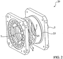
- the figure 2 illustrates a heat generator 20 produced according to the principle of the thermal generator 10 described in the Figures 1A and 1B .
- This heat generator 20 has a circular structure comprising magnetocaloric elements 2 adjacent and arranged in a circular ring.
- the two exchange means 25 are each in the form of a circular ring, made of a thermally conductive material or not, and having, on the one hand, through passages 9 allowing the coolant to move through them.
- magnetocaloric elements 2 under the action of the pistons 7 and, secondly, a circuit for the circulation of an external fluid. This circuit is not visible on the figure 2 .
- the connecting means of this circuit such as tips or similar means are not shown in this figure either.
- the advantage of such a heat generator 20 is its compactness.
- the figure 3A represents an example of an industrial embodiment of an exchange means 45 in the form of a circular ring that can enter the construction of the heat generator 20 of the figure 2 . It comprises a ring 40 provided with through-passages 9 for the coolant, formed for example by perforations oriented axially and arranged in correspondence of one side of each magnetocaloric element 2 and the other side of each piston 7 without loss of load.
- the outer 41 and inner 42 walls of this ring 40 comprise grooves 46, oriented radially and respectively closed by an outer ring 43 and an inner ring 44 to form the ducts of an internal circuit 11 'and an external circuit 11 in which flows an external fluid transferring by a fluid / fluid exchange the thermal energy produced by the generator 20.
- the rings 43 and 44 are assembled to the ring 40 by any suitable method for obtaining a sealed assembly, such as by clamping, crimping, casting, welding, etc.
- This method of construction has the advantage of being easy to industrialize at lower cost and to create circuits 11, 11 'for the circulation of an external fluid with a very large heat exchange surface and allowing a more constant laminar flow.
- the realization of two parallel circuits 11, 11 ', arranged on either side of the exchange means 45 with the magnetocaloric element 2 allows heat transfer homogeneously when several magnetocaloric elements 2 are juxtaposed. This homogenization of the temperature is obtained and improved by circulating the fluid in the internal circuit 11 'in the opposite direction to the fluid flowing in the external circuit 11.
- the efficiency of the heat exchange can be further improved by dividing the circuits 11 and 11 'in several sectors connected in parallel.
- the Figures 4A and 4B represent an alternative embodiment of a thermal generator 30 comprising a magnetocaloric element 2 constituted by two magnetocaloric materials 21 and 22. These magnetocaloric materials 21 and 22 are constantly in an opposite magnetic state, that is to say when one 21 of said magnetocaloric materials is subjected to a magnetic field, the other magnetocaloric material 22 is out of the magnetic field, and vice versa.
- the first and second ends 3 and 4 are each materialized by one end of each magnetocaloric material 21,22.
- An exchange means 35, 35 'identical to the exchange means 15 mounted in the generator 10 Figures 1A and 1B is mounted adjacent to each of said ends 3 and 4.
- the heat transfer fluid is circulated through said magnetocaloric materials 21, 22 by three drive means 7, 7 ', namely two pistons 7 each located at one end of said magnetocaloric element 2 and a piston 7 'whose chamber is connected to a cell 17 common to the two materials 21 and 22 and fluidly connecting them.
- the magnetocaloric material 21 located on the left in the figure is magnetically activated and the magnetocaloric material 22 on the right in the figure is magnetically deactivated.
- the heat transfer fluid flows from left to right in the magnetocaloric material 21 on the left and from the right to the left in the magnetocaloric material 22 on the right, towards the common cell 17.
- the coolant thus flows simultaneously, on the one hand, the transfer zone 8 of the exchange means 35 located on the side of the first end 3, which allows the thermal energy to be exchanged with the heat transfer fluid before its reintegration in the magnetocaloric material 21 on the left and, on the other hand, the transfer zone 8 of the exchange means 35 'situated on the side of the second end 4, which makes it possible to exchange thermal energy with the heat transfer fluid before its reintegration in the magnetocaloric material 22 located on the right.
- the magnetocaloric material 21 on the left in the figure is magnetically deactivated and the magnetocaloric material 22 on the right in the figure is magnetically activated.
- the coolant exits the common cell 17 and circulates from right to left in the magnetocaloric material 21 located on the left and from left to right in the magnetocaloric material 22 on the right.
- the heat transfer fluid thus passes, again, simultaneously, firstly, the magnetocaloric material 21 located on the left while cooling and also the transfer zone 8 of the exchange means 35 located on the side of the first end 3 , and, on the other hand, the magnetocaloric material 22 located on the right while heating up and also the transfer zone 8 of the exchange means 35 'situated on the side of the second end 4.
- each magnetic cycle or heating and cooling cycle is operated, so that the maximum of thermal energy can be recovered or exchanged at each end 3 and 4 of the magnetocaloric element 2 of the thermal generator 30.
- the exchange means 15, 25, 35, 35 ', 45 is integrated inside said generators and arranged contiguously at each end 3, 4 of the or magnetocaloric elements 2.
- the invention is however not limited to this type of configuration and also provides that all the ends 3, 4 are not related to such exchange means 15, 25, 35, 35 ', 45 and only one of the ends 3 and 4 is.
- Such a heat generator 10, 20, 30 can find an industrial and domestic application in the field of heating, air conditioning, tempering, cooling or the like, at competitive costs, for a small footprint.
Landscapes
- Engineering & Computer Science (AREA)
- Physics & Mathematics (AREA)
- Mechanical Engineering (AREA)
- Thermal Sciences (AREA)
- General Engineering & Computer Science (AREA)
- General Induction Heating (AREA)
- Heat-Exchange Devices With Radiators And Conduit Assemblies (AREA)
- Thermotherapy And Cooling Therapy Devices (AREA)
Priority Applications (1)
| Application Number | Priority Date | Filing Date | Title |
|---|---|---|---|
| PL10708237T PL2399088T3 (pl) | 2009-02-17 | 2010-02-15 | Magnetokaloryczny generator cieplny |
Applications Claiming Priority (2)
| Application Number | Priority Date | Filing Date | Title |
|---|---|---|---|
| FR0951019A FR2942304B1 (fr) | 2009-02-17 | 2009-02-17 | Generateur thermique magnetocalorique |
| PCT/FR2010/000127 WO2010094855A1 (fr) | 2009-02-17 | 2010-02-15 | Generateur thermique magnetocalorique |
Publications (2)
| Publication Number | Publication Date |
|---|---|
| EP2399088A1 EP2399088A1 (fr) | 2011-12-28 |
| EP2399088B1 true EP2399088B1 (fr) | 2016-12-21 |
Family
ID=41136934
Family Applications (1)
| Application Number | Title | Priority Date | Filing Date |
|---|---|---|---|
| EP10708237.2A Not-in-force EP2399088B1 (fr) | 2009-02-17 | 2010-02-15 | Generateur thermique magnetocalorique |
Country Status (12)
| Country | Link |
|---|---|
| US (1) | US9249999B2 (ko) |
| EP (1) | EP2399088B1 (ko) |
| JP (1) | JP6086340B2 (ko) |
| KR (1) | KR101688244B1 (ko) |
| CN (1) | CN102317710B (ko) |
| BR (1) | BRPI1007284A2 (ko) |
| ES (1) | ES2619553T3 (ko) |
| FR (1) | FR2942304B1 (ko) |
| HK (1) | HK1164987A1 (ko) |
| MX (1) | MX2011008508A (ko) |
| PL (1) | PL2399088T3 (ko) |
| WO (1) | WO2010094855A1 (ko) |
Families Citing this family (6)
| Publication number | Priority date | Publication date | Assignee | Title |
|---|---|---|---|---|
| FR2982015B1 (fr) * | 2011-10-28 | 2019-03-15 | Cooltech Applications | Generateur thermique magnetocalorique |
| JP5776579B2 (ja) * | 2012-02-17 | 2015-09-09 | 株式会社デンソー | 磁気ヒートポンプシステムのピストンポンプ |
| JP5949159B2 (ja) * | 2012-05-25 | 2016-07-06 | 株式会社デンソー | 磁気ヒートポンプシステム |
| JP6365173B2 (ja) * | 2014-09-23 | 2018-08-01 | 株式会社デンソー | 磁気ヒートポンプ装置 |
| CN104748012A (zh) * | 2015-03-28 | 2015-07-01 | 朱惠冲 | 大功率led灯 |
| DE102016120043A1 (de) | 2016-10-20 | 2018-04-26 | Ke-Kelit Kunststoffwerk Gmbh | Thermisches Verbinden von Kunststoffobjekten mittels Aufheizmittel mit geringer Curie-Temperatur |
Family Cites Families (24)
| Publication number | Priority date | Publication date | Assignee | Title |
|---|---|---|---|---|
| US9001A (en) * | 1852-06-08 | Keflector-lamp | ||
| BE597985A (fr) * | 1960-04-01 | 1961-06-09 | Du Pont | Compositions ferromagnétiques, procédé pour leur obtention et dispositifs en contenant. |
| NL6602744A (ko) * | 1966-03-03 | 1967-09-04 | ||
| JPH0268465A (ja) * | 1988-08-31 | 1990-03-07 | Shirakawa Shiro | 冷却ならびに、加熱装置 |
| JPH02103348A (ja) * | 1988-10-12 | 1990-04-16 | Mitsubishi Electric Corp | 磁気冷凍装置 |
| US5249424A (en) * | 1992-06-05 | 1993-10-05 | Astronautics Corporation Of America | Active magnetic regenerator method and apparatus |
| JP3582366B2 (ja) * | 1998-07-06 | 2004-10-27 | ダイキン工業株式会社 | 送風機 |
| US6293106B1 (en) * | 2000-05-18 | 2001-09-25 | Praxair Technology, Inc. | Magnetic refrigeration system with multicomponent refrigerant fluid forecooling |
| US6896041B2 (en) * | 2001-08-14 | 2005-05-24 | H2Gen Innovations, Inc. | Heat exchange reactor having integral housing assembly |
| JP2003279275A (ja) * | 2002-03-22 | 2003-10-02 | Matsushita Electric Ind Co Ltd | 熱交換器およびその熱交換器を用いた冷凍サイクル装置 |
| CH695837A5 (fr) * | 2002-12-24 | 2006-09-15 | Ecole D Ingenieurs Du Canton D | Procéde et dispositif de génération de froid et de chaleur par effet magnétique. |
| CH695836A5 (fr) * | 2002-12-24 | 2006-09-15 | Ecole D Ingenieurs Du Canton D | Procédé et dispositif pour générer en continu du froid et de la chaleur par effet magnetique. |
| FR2861454B1 (fr) * | 2003-10-23 | 2006-09-01 | Christian Muller | Dispositif de generation de flux thermique a materiau magneto-calorique |
| FR2864211B1 (fr) * | 2003-12-23 | 2007-01-12 | Christian Muller | Echangeur thermique comportant des moyens de raccordement d'elements thermiques de chauffage et de refroidissement |
| FR2868519B1 (fr) * | 2004-03-30 | 2006-06-16 | Christian Muller | Generateur thermique a materiau magneto-calorique et procede de generation de thermies |
| BRPI0519822A2 (pt) * | 2005-01-12 | 2009-03-17 | Univ Denmark Tech Dtu | métodos para fazer um regenerador magnético para um refrigerador magnético ativo e para fazer um refrigerador magnético ativo, refrigerador magnético, e, regenerador magnético |
| FR2890158A1 (fr) * | 2005-09-01 | 2007-03-02 | Cooltech Applic Soc Par Action | Generateur thermique a materiau magnetocalorique |
| KR100647854B1 (ko) * | 2005-11-10 | 2006-11-23 | 주식회사 대우일렉트로닉스 | 자기냉동기 |
| JP4533838B2 (ja) * | 2005-12-06 | 2010-09-01 | 株式会社東芝 | 熱輸送装置、冷凍機及びヒートポンプ |
| KR100684521B1 (ko) * | 2005-12-21 | 2007-02-20 | 주식회사 대우일렉트로닉스 | 자기냉동기 |
| DE102006006326B4 (de) * | 2006-02-11 | 2007-12-06 | Bruker Biospin Ag | Hybrid-Wärmepumpe/Kältemaschine mit magnetischer Kühlstufe |
| JP2007263392A (ja) * | 2006-03-27 | 2007-10-11 | Toshiba Corp | 磁気冷凍材料及び磁気冷凍装置 |
| US8209988B2 (en) * | 2008-09-24 | 2012-07-03 | Husssmann Corporation | Magnetic refrigeration device |
| GB0903974D0 (en) * | 2009-03-09 | 2009-04-22 | Univ Denmark Tech Dtu | A parallel magnetic refrigeration assembly and a method of refrigeration |
-
2009
- 2009-02-17 FR FR0951019A patent/FR2942304B1/fr not_active Expired - Fee Related
-
2010
- 2010-02-15 PL PL10708237T patent/PL2399088T3/pl unknown
- 2010-02-15 JP JP2011549629A patent/JP6086340B2/ja not_active Expired - Fee Related
- 2010-02-15 CN CN201080007987XA patent/CN102317710B/zh not_active Expired - Fee Related
- 2010-02-15 MX MX2011008508A patent/MX2011008508A/es not_active Application Discontinuation
- 2010-02-15 WO PCT/FR2010/000127 patent/WO2010094855A1/fr active Application Filing
- 2010-02-15 BR BRPI1007284A patent/BRPI1007284A2/pt not_active IP Right Cessation
- 2010-02-15 KR KR1020117019092A patent/KR101688244B1/ko active IP Right Grant
- 2010-02-15 ES ES10708237.2T patent/ES2619553T3/es active Active
- 2010-02-15 EP EP10708237.2A patent/EP2399088B1/fr not_active Not-in-force
- 2010-02-15 US US13/147,441 patent/US9249999B2/en not_active Expired - Fee Related
-
2012
- 2012-06-05 HK HK12105441.0A patent/HK1164987A1/xx not_active IP Right Cessation
Non-Patent Citations (1)
| Title |
|---|
| None * |
Also Published As
| Publication number | Publication date |
|---|---|
| US20110289938A1 (en) | 2011-12-01 |
| KR101688244B1 (ko) | 2016-12-20 |
| CN102317710B (zh) | 2013-07-31 |
| FR2942304A1 (fr) | 2010-08-20 |
| WO2010094855A1 (fr) | 2010-08-26 |
| JP6086340B2 (ja) | 2017-03-01 |
| ES2619553T3 (es) | 2017-06-26 |
| US9249999B2 (en) | 2016-02-02 |
| FR2942304B1 (fr) | 2011-08-12 |
| PL2399088T3 (pl) | 2017-06-30 |
| MX2011008508A (es) | 2011-09-01 |
| EP2399088A1 (fr) | 2011-12-28 |
| CN102317710A (zh) | 2012-01-11 |
| HK1164987A1 (en) | 2012-09-28 |
| BRPI1007284A2 (pt) | 2016-09-06 |
| KR20110127151A (ko) | 2011-11-24 |
| JP2012518150A (ja) | 2012-08-09 |
Similar Documents
| Publication | Publication Date | Title |
|---|---|---|
| EP2409093B1 (fr) | Generateur thermique magnetocalorique et son procede d'echange thermique | |
| EP2399087B1 (fr) | Generateur thermique magnetocalorique | |
| EP2399088B1 (fr) | Generateur thermique magnetocalorique | |
| EP2340571B1 (fr) | Generateur thermioue a materiau magnetocalorioue | |
| EP2129976B1 (fr) | Procede et dispositif pour accroitre le gradient de temperature dans un generateur thermique magnetocalorique | |
| EP2044373B1 (fr) | Generateur thermique magnetocalorioue | |
| EP2783170B1 (fr) | Generateur thermique magnetocalorique | |
| WO2013060946A1 (fr) | Generateur thermique magnetocalorique | |
| CA2929855C (fr) | Appareil thermique magnetocalorique | |
| WO2010046559A1 (fr) | Generateur thermique magnetocalorique | |
| WO2010043782A1 (fr) | Generateur thermioue magnetocalorioue | |
| EP2603747B1 (fr) | Generateur thermique a materiau magnetocalorique | |
| EP3087329B1 (fr) | Générateur thermique magnetocalorique et son procédé de refroidissement | |
| EP2318784B1 (fr) | Generateur thermique a materiau magnetocalorique | |
| EP2972045B1 (fr) | Appareil thermique | |
| EP3087328B1 (fr) | Appareil thermique et son procede d'optimisation d'echange thermique | |
| FR2963668A1 (fr) | Generateur thermique a materiau magnetocalorique | |
| FR2963823A1 (fr) | Generateur thermique magnetocalorique |
Legal Events
| Date | Code | Title | Description |
|---|---|---|---|
| PUAI | Public reference made under article 153(3) epc to a published international application that has entered the european phase |
Free format text: ORIGINAL CODE: 0009012 |
|
| 17P | Request for examination filed |
Effective date: 20110812 |
|
| AK | Designated contracting states |
Kind code of ref document: A1 Designated state(s): AT BE BG CH CY CZ DE DK EE ES FI FR GB GR HR HU IE IS IT LI LT LU LV MC MK MT NL NO PL PT RO SE SI SK SM TR |
|
| DAX | Request for extension of the european patent (deleted) | ||
| 17Q | First examination report despatched |
Effective date: 20140212 |
|
| GRAP | Despatch of communication of intention to grant a patent |
Free format text: ORIGINAL CODE: EPIDOSNIGR1 |
|
| INTG | Intention to grant announced |
Effective date: 20160620 |
|
| GRAJ | Information related to disapproval of communication of intention to grant by the applicant or resumption of examination proceedings by the epo deleted |
Free format text: ORIGINAL CODE: EPIDOSDIGR1 |
|
| GRAR | Information related to intention to grant a patent recorded |
Free format text: ORIGINAL CODE: EPIDOSNIGR71 |
|
| GRAS | Grant fee paid |
Free format text: ORIGINAL CODE: EPIDOSNIGR3 |
|
| INTC | Intention to grant announced (deleted) | ||
| GRAA | (expected) grant |
Free format text: ORIGINAL CODE: 0009210 |
|
| INTG | Intention to grant announced |
Effective date: 20161104 |
|
| AK | Designated contracting states |
Kind code of ref document: B1 Designated state(s): AT BE BG CH CY CZ DE DK EE ES FI FR GB GR HR HU IE IS IT LI LT LU LV MC MK MT NL NO PL PT RO SE SI SK SM TR |
|
| REG | Reference to a national code |
Ref country code: GB Ref legal event code: FG4D Free format text: NOT ENGLISH |
|
| REG | Reference to a national code |
Ref country code: CH Ref legal event code: EP |
|
| REG | Reference to a national code |
Ref country code: IE Ref legal event code: FG4D Free format text: LANGUAGE OF EP DOCUMENT: FRENCH |
|
| REG | Reference to a national code |
Ref country code: AT Ref legal event code: REF Ref document number: 855844 Country of ref document: AT Kind code of ref document: T Effective date: 20170115 |
|
| REG | Reference to a national code |
Ref country code: DE Ref legal event code: R096 Ref document number: 602010038941 Country of ref document: DE |
|
| REG | Reference to a national code |
Ref country code: FR Ref legal event code: PLFP Year of fee payment: 8 |
|
| PG25 | Lapsed in a contracting state [announced via postgrant information from national office to epo] |
Ref country code: LV Free format text: LAPSE BECAUSE OF FAILURE TO SUBMIT A TRANSLATION OF THE DESCRIPTION OR TO PAY THE FEE WITHIN THE PRESCRIBED TIME-LIMIT Effective date: 20161221 |
|
| REG | Reference to a national code |
Ref country code: LT Ref legal event code: MG4D |
|
| REG | Reference to a national code |
Ref country code: NL Ref legal event code: MP Effective date: 20161221 |
|
| PG25 | Lapsed in a contracting state [announced via postgrant information from national office to epo] |
Ref country code: LT Free format text: LAPSE BECAUSE OF FAILURE TO SUBMIT A TRANSLATION OF THE DESCRIPTION OR TO PAY THE FEE WITHIN THE PRESCRIBED TIME-LIMIT Effective date: 20161221 Ref country code: SE Free format text: LAPSE BECAUSE OF FAILURE TO SUBMIT A TRANSLATION OF THE DESCRIPTION OR TO PAY THE FEE WITHIN THE PRESCRIBED TIME-LIMIT Effective date: 20161221 Ref country code: NO Free format text: LAPSE BECAUSE OF FAILURE TO SUBMIT A TRANSLATION OF THE DESCRIPTION OR TO PAY THE FEE WITHIN THE PRESCRIBED TIME-LIMIT Effective date: 20170321 Ref country code: GR Free format text: LAPSE BECAUSE OF FAILURE TO SUBMIT A TRANSLATION OF THE DESCRIPTION OR TO PAY THE FEE WITHIN THE PRESCRIBED TIME-LIMIT Effective date: 20170322 |
|
| REG | Reference to a national code |
Ref country code: AT Ref legal event code: MK05 Ref document number: 855844 Country of ref document: AT Kind code of ref document: T Effective date: 20161221 |
|
| PG25 | Lapsed in a contracting state [announced via postgrant information from national office to epo] |
Ref country code: BE Free format text: LAPSE BECAUSE OF NON-PAYMENT OF DUE FEES Effective date: 20170228 Ref country code: FI Free format text: LAPSE BECAUSE OF FAILURE TO SUBMIT A TRANSLATION OF THE DESCRIPTION OR TO PAY THE FEE WITHIN THE PRESCRIBED TIME-LIMIT Effective date: 20161221 Ref country code: HR Free format text: LAPSE BECAUSE OF FAILURE TO SUBMIT A TRANSLATION OF THE DESCRIPTION OR TO PAY THE FEE WITHIN THE PRESCRIBED TIME-LIMIT Effective date: 20161221 |
|
| PGFP | Annual fee paid to national office [announced via postgrant information from national office to epo] |
Ref country code: GB Payment date: 20170127 Year of fee payment: 8 |
|
| REG | Reference to a national code |
Ref country code: ES Ref legal event code: FG2A Ref document number: 2619553 Country of ref document: ES Kind code of ref document: T3 Effective date: 20170626 |
|
| PG25 | Lapsed in a contracting state [announced via postgrant information from national office to epo] |
Ref country code: NL Free format text: LAPSE BECAUSE OF FAILURE TO SUBMIT A TRANSLATION OF THE DESCRIPTION OR TO PAY THE FEE WITHIN THE PRESCRIBED TIME-LIMIT Effective date: 20161221 |
|
| PG25 | Lapsed in a contracting state [announced via postgrant information from national office to epo] |
Ref country code: EE Free format text: LAPSE BECAUSE OF FAILURE TO SUBMIT A TRANSLATION OF THE DESCRIPTION OR TO PAY THE FEE WITHIN THE PRESCRIBED TIME-LIMIT Effective date: 20161221 Ref country code: IS Free format text: LAPSE BECAUSE OF FAILURE TO SUBMIT A TRANSLATION OF THE DESCRIPTION OR TO PAY THE FEE WITHIN THE PRESCRIBED TIME-LIMIT Effective date: 20170421 Ref country code: RO Free format text: LAPSE BECAUSE OF FAILURE TO SUBMIT A TRANSLATION OF THE DESCRIPTION OR TO PAY THE FEE WITHIN THE PRESCRIBED TIME-LIMIT Effective date: 20161221 Ref country code: CZ Free format text: LAPSE BECAUSE OF FAILURE TO SUBMIT A TRANSLATION OF THE DESCRIPTION OR TO PAY THE FEE WITHIN THE PRESCRIBED TIME-LIMIT Effective date: 20161221 Ref country code: SK Free format text: LAPSE BECAUSE OF FAILURE TO SUBMIT A TRANSLATION OF THE DESCRIPTION OR TO PAY THE FEE WITHIN THE PRESCRIBED TIME-LIMIT Effective date: 20161221 |
|
| PG25 | Lapsed in a contracting state [announced via postgrant information from national office to epo] |
Ref country code: BG Free format text: LAPSE BECAUSE OF FAILURE TO SUBMIT A TRANSLATION OF THE DESCRIPTION OR TO PAY THE FEE WITHIN THE PRESCRIBED TIME-LIMIT Effective date: 20170321 Ref country code: SM Free format text: LAPSE BECAUSE OF FAILURE TO SUBMIT A TRANSLATION OF THE DESCRIPTION OR TO PAY THE FEE WITHIN THE PRESCRIBED TIME-LIMIT Effective date: 20161221 Ref country code: PT Free format text: LAPSE BECAUSE OF FAILURE TO SUBMIT A TRANSLATION OF THE DESCRIPTION OR TO PAY THE FEE WITHIN THE PRESCRIBED TIME-LIMIT Effective date: 20170421 Ref country code: AT Free format text: LAPSE BECAUSE OF FAILURE TO SUBMIT A TRANSLATION OF THE DESCRIPTION OR TO PAY THE FEE WITHIN THE PRESCRIBED TIME-LIMIT Effective date: 20161221 |
|
| PGFP | Annual fee paid to national office [announced via postgrant information from national office to epo] |
Ref country code: PL Payment date: 20170127 Year of fee payment: 8 |
|
| REG | Reference to a national code |
Ref country code: DE Ref legal event code: R097 Ref document number: 602010038941 Country of ref document: DE |
|
| PG25 | Lapsed in a contracting state [announced via postgrant information from national office to epo] |
Ref country code: MC Free format text: LAPSE BECAUSE OF FAILURE TO SUBMIT A TRANSLATION OF THE DESCRIPTION OR TO PAY THE FEE WITHIN THE PRESCRIBED TIME-LIMIT Effective date: 20161221 |
|
| REG | Reference to a national code |
Ref country code: CH Ref legal event code: PL |
|
| PLBE | No opposition filed within time limit |
Free format text: ORIGINAL CODE: 0009261 |
|
| STAA | Information on the status of an ep patent application or granted ep patent |
Free format text: STATUS: NO OPPOSITION FILED WITHIN TIME LIMIT |
|
| PG25 | Lapsed in a contracting state [announced via postgrant information from national office to epo] |
Ref country code: LI Free format text: LAPSE BECAUSE OF NON-PAYMENT OF DUE FEES Effective date: 20170228 Ref country code: CH Free format text: LAPSE BECAUSE OF NON-PAYMENT OF DUE FEES Effective date: 20170228 |
|
| 26N | No opposition filed |
Effective date: 20170922 |
|
| REG | Reference to a national code |
Ref country code: IE Ref legal event code: MM4A |
|
| PG25 | Lapsed in a contracting state [announced via postgrant information from national office to epo] |
Ref country code: DK Free format text: LAPSE BECAUSE OF FAILURE TO SUBMIT A TRANSLATION OF THE DESCRIPTION OR TO PAY THE FEE WITHIN THE PRESCRIBED TIME-LIMIT Effective date: 20161221 |
|
| PG25 | Lapsed in a contracting state [announced via postgrant information from national office to epo] |
Ref country code: LU Free format text: LAPSE BECAUSE OF NON-PAYMENT OF DUE FEES Effective date: 20170215 |
|
| REG | Reference to a national code |
Ref country code: FR Ref legal event code: PLFP Year of fee payment: 9 |
|
| REG | Reference to a national code |
Ref country code: BE Ref legal event code: MM Effective date: 20170228 |
|
| PG25 | Lapsed in a contracting state [announced via postgrant information from national office to epo] |
Ref country code: SI Free format text: LAPSE BECAUSE OF FAILURE TO SUBMIT A TRANSLATION OF THE DESCRIPTION OR TO PAY THE FEE WITHIN THE PRESCRIBED TIME-LIMIT Effective date: 20161221 Ref country code: IE Free format text: LAPSE BECAUSE OF NON-PAYMENT OF DUE FEES Effective date: 20170215 |
|
| PGFP | Annual fee paid to national office [announced via postgrant information from national office to epo] |
Ref country code: ES Payment date: 20180302 Year of fee payment: 9 |
|
| PGFP | Annual fee paid to national office [announced via postgrant information from national office to epo] |
Ref country code: IT Payment date: 20180208 Year of fee payment: 9 |
|
| PG25 | Lapsed in a contracting state [announced via postgrant information from national office to epo] |
Ref country code: MT Free format text: LAPSE BECAUSE OF FAILURE TO SUBMIT A TRANSLATION OF THE DESCRIPTION OR TO PAY THE FEE WITHIN THE PRESCRIBED TIME-LIMIT Effective date: 20161221 |
|
| GBPC | Gb: european patent ceased through non-payment of renewal fee |
Effective date: 20180215 |
|
| PG25 | Lapsed in a contracting state [announced via postgrant information from national office to epo] |
Ref country code: GB Free format text: LAPSE BECAUSE OF NON-PAYMENT OF DUE FEES Effective date: 20180215 |
|
| PGFP | Annual fee paid to national office [announced via postgrant information from national office to epo] |
Ref country code: DE Payment date: 20190312 Year of fee payment: 10 |
|
| PGFP | Annual fee paid to national office [announced via postgrant information from national office to epo] |
Ref country code: FR Payment date: 20190225 Year of fee payment: 10 |
|
| PG25 | Lapsed in a contracting state [announced via postgrant information from national office to epo] |
Ref country code: HU Free format text: LAPSE BECAUSE OF FAILURE TO SUBMIT A TRANSLATION OF THE DESCRIPTION OR TO PAY THE FEE WITHIN THE PRESCRIBED TIME-LIMIT; INVALID AB INITIO Effective date: 20100215 |
|
| PG25 | Lapsed in a contracting state [announced via postgrant information from national office to epo] |
Ref country code: CY Free format text: LAPSE BECAUSE OF NON-PAYMENT OF DUE FEES Effective date: 20161221 |
|
| PG25 | Lapsed in a contracting state [announced via postgrant information from national office to epo] |
Ref country code: MK Free format text: LAPSE BECAUSE OF FAILURE TO SUBMIT A TRANSLATION OF THE DESCRIPTION OR TO PAY THE FEE WITHIN THE PRESCRIBED TIME-LIMIT Effective date: 20161221 Ref country code: PL Free format text: LAPSE BECAUSE OF NON-PAYMENT OF DUE FEES Effective date: 20180215 |
|
| PG25 | Lapsed in a contracting state [announced via postgrant information from national office to epo] |
Ref country code: IT Free format text: LAPSE BECAUSE OF NON-PAYMENT OF DUE FEES Effective date: 20190215 |
|
| REG | Reference to a national code |
Ref country code: ES Ref legal event code: FD2A Effective date: 20200330 |
|
| PG25 | Lapsed in a contracting state [announced via postgrant information from national office to epo] |
Ref country code: TR Free format text: LAPSE BECAUSE OF FAILURE TO SUBMIT A TRANSLATION OF THE DESCRIPTION OR TO PAY THE FEE WITHIN THE PRESCRIBED TIME-LIMIT Effective date: 20161221 |
|
| PG25 | Lapsed in a contracting state [announced via postgrant information from national office to epo] |
Ref country code: ES Free format text: LAPSE BECAUSE OF NON-PAYMENT OF DUE FEES Effective date: 20190216 |
|
| REG | Reference to a national code |
Ref country code: DE Ref legal event code: R119 Ref document number: 602010038941 Country of ref document: DE |
|
| PG25 | Lapsed in a contracting state [announced via postgrant information from national office to epo] |
Ref country code: FR Free format text: LAPSE BECAUSE OF NON-PAYMENT OF DUE FEES Effective date: 20200229 Ref country code: DE Free format text: LAPSE BECAUSE OF NON-PAYMENT OF DUE FEES Effective date: 20200901 |