EP2398719B1 - Insulated storage tank - Google Patents
Insulated storage tank Download PDFInfo
- Publication number
- EP2398719B1 EP2398719B1 EP10744367.3A EP10744367A EP2398719B1 EP 2398719 B1 EP2398719 B1 EP 2398719B1 EP 10744367 A EP10744367 A EP 10744367A EP 2398719 B1 EP2398719 B1 EP 2398719B1
- Authority
- EP
- European Patent Office
- Prior art keywords
- storage tank
- insulating panels
- liquid
- insulating
- lid
- Prior art date
- Legal status (The legal status is an assumption and is not a legal conclusion. Google has not performed a legal analysis and makes no representation as to the accuracy of the status listed.)
- Active
Links
Images



Classifications
-
- F—MECHANICAL ENGINEERING; LIGHTING; HEATING; WEAPONS; BLASTING
- F24—HEATING; RANGES; VENTILATING
- F24H—FLUID HEATERS, e.g. WATER OR AIR HEATERS, HAVING HEAT-GENERATING MEANS, e.g. HEAT PUMPS, IN GENERAL
- F24H1/00—Water heaters, e.g. boilers, continuous-flow heaters or water-storage heaters
- F24H1/18—Water-storage heaters
- F24H1/181—Construction of the tank
- F24H1/182—Insulation
-
- B—PERFORMING OPERATIONS; TRANSPORTING
- B65—CONVEYING; PACKING; STORING; HANDLING THIN OR FILAMENTARY MATERIAL
- B65D—CONTAINERS FOR STORAGE OR TRANSPORT OF ARTICLES OR MATERIALS, e.g. BAGS, BARRELS, BOTTLES, BOXES, CANS, CARTONS, CRATES, DRUMS, JARS, TANKS, HOPPERS, FORWARDING CONTAINERS; ACCESSORIES, CLOSURES, OR FITTINGS THEREFOR; PACKAGING ELEMENTS; PACKAGES
- B65D90/00—Component parts, details or accessories for large containers
- B65D90/02—Wall construction
- B65D90/06—Coverings, e.g. for insulating purposes
-
- B—PERFORMING OPERATIONS; TRANSPORTING
- B65—CONVEYING; PACKING; STORING; HANDLING THIN OR FILAMENTARY MATERIAL
- B65D—CONTAINERS FOR STORAGE OR TRANSPORT OF ARTICLES OR MATERIALS, e.g. BAGS, BARRELS, BOTTLES, BOXES, CANS, CARTONS, CRATES, DRUMS, JARS, TANKS, HOPPERS, FORWARDING CONTAINERS; ACCESSORIES, CLOSURES, OR FITTINGS THEREFOR; PACKAGING ELEMENTS; PACKAGES
- B65D88/00—Large containers
- B65D88/02—Large containers rigid
- B65D88/06—Large containers rigid cylindrical
-
- B—PERFORMING OPERATIONS; TRANSPORTING
- B65—CONVEYING; PACKING; STORING; HANDLING THIN OR FILAMENTARY MATERIAL
- B65D—CONTAINERS FOR STORAGE OR TRANSPORT OF ARTICLES OR MATERIALS, e.g. BAGS, BARRELS, BOTTLES, BOXES, CANS, CARTONS, CRATES, DRUMS, JARS, TANKS, HOPPERS, FORWARDING CONTAINERS; ACCESSORIES, CLOSURES, OR FITTINGS THEREFOR; PACKAGING ELEMENTS; PACKAGES
- B65D90/00—Component parts, details or accessories for large containers
- B65D90/02—Wall construction
- B65D90/04—Linings
-
- B—PERFORMING OPERATIONS; TRANSPORTING
- B65—CONVEYING; PACKING; STORING; HANDLING THIN OR FILAMENTARY MATERIAL
- B65D—CONTAINERS FOR STORAGE OR TRANSPORT OF ARTICLES OR MATERIALS, e.g. BAGS, BARRELS, BOTTLES, BOXES, CANS, CARTONS, CRATES, DRUMS, JARS, TANKS, HOPPERS, FORWARDING CONTAINERS; ACCESSORIES, CLOSURES, OR FITTINGS THEREFOR; PACKAGING ELEMENTS; PACKAGES
- B65D90/00—Component parts, details or accessories for large containers
- B65D90/48—Arrangements of indicating or measuring devices
-
- F—MECHANICAL ENGINEERING; LIGHTING; HEATING; WEAPONS; BLASTING
- F16—ENGINEERING ELEMENTS AND UNITS; GENERAL MEASURES FOR PRODUCING AND MAINTAINING EFFECTIVE FUNCTIONING OF MACHINES OR INSTALLATIONS; THERMAL INSULATION IN GENERAL
- F16L—PIPES; JOINTS OR FITTINGS FOR PIPES; SUPPORTS FOR PIPES, CABLES OR PROTECTIVE TUBING; MEANS FOR THERMAL INSULATION IN GENERAL
- F16L59/00—Thermal insulation in general
- F16L59/02—Shape or form of insulating materials, with or without coverings integral with the insulating materials
- F16L59/021—Shape or form of insulating materials, with or without coverings integral with the insulating materials comprising a single piece or sleeve, e.g. split sleeves; consisting of two half sleeves; comprising more than two segments
- F16L59/025—Shape or form of insulating materials, with or without coverings integral with the insulating materials comprising a single piece or sleeve, e.g. split sleeves; consisting of two half sleeves; comprising more than two segments comprising more than two segments
-
- F—MECHANICAL ENGINEERING; LIGHTING; HEATING; WEAPONS; BLASTING
- F28—HEAT EXCHANGE IN GENERAL
- F28D—HEAT-EXCHANGE APPARATUS, NOT PROVIDED FOR IN ANOTHER SUBCLASS, IN WHICH THE HEAT-EXCHANGE MEDIA DO NOT COME INTO DIRECT CONTACT
- F28D20/00—Heat storage plants or apparatus in general; Regenerative heat-exchange apparatus not covered by groups F28D17/00 or F28D19/00
- F28D20/0034—Heat storage plants or apparatus in general; Regenerative heat-exchange apparatus not covered by groups F28D17/00 or F28D19/00 using liquid heat storage material
-
- F—MECHANICAL ENGINEERING; LIGHTING; HEATING; WEAPONS; BLASTING
- F24—HEATING; RANGES; VENTILATING
- F24S—SOLAR HEAT COLLECTORS; SOLAR HEAT SYSTEMS
- F24S60/00—Arrangements for storing heat collected by solar heat collectors
- F24S60/30—Arrangements for storing heat collected by solar heat collectors storing heat in liquids
-
- F—MECHANICAL ENGINEERING; LIGHTING; HEATING; WEAPONS; BLASTING
- F28—HEAT EXCHANGE IN GENERAL
- F28D—HEAT-EXCHANGE APPARATUS, NOT PROVIDED FOR IN ANOTHER SUBCLASS, IN WHICH THE HEAT-EXCHANGE MEDIA DO NOT COME INTO DIRECT CONTACT
- F28D20/00—Heat storage plants or apparatus in general; Regenerative heat-exchange apparatus not covered by groups F28D17/00 or F28D19/00
- F28D2020/0065—Details, e.g. particular heat storage tanks, auxiliary members within tanks
-
- F—MECHANICAL ENGINEERING; LIGHTING; HEATING; WEAPONS; BLASTING
- F28—HEAT EXCHANGE IN GENERAL
- F28F—DETAILS OF HEAT-EXCHANGE AND HEAT-TRANSFER APPARATUS, OF GENERAL APPLICATION
- F28F2270/00—Thermal insulation; Thermal decoupling
-
- Y—GENERAL TAGGING OF NEW TECHNOLOGICAL DEVELOPMENTS; GENERAL TAGGING OF CROSS-SECTIONAL TECHNOLOGIES SPANNING OVER SEVERAL SECTIONS OF THE IPC; TECHNICAL SUBJECTS COVERED BY FORMER USPC CROSS-REFERENCE ART COLLECTIONS [XRACs] AND DIGESTS
- Y02—TECHNOLOGIES OR APPLICATIONS FOR MITIGATION OR ADAPTATION AGAINST CLIMATE CHANGE
- Y02E—REDUCTION OF GREENHOUSE GAS [GHG] EMISSIONS, RELATED TO ENERGY GENERATION, TRANSMISSION OR DISTRIBUTION
- Y02E60/00—Enabling technologies; Technologies with a potential or indirect contribution to GHG emissions mitigation
- Y02E60/14—Thermal energy storage
-
- Y—GENERAL TAGGING OF NEW TECHNOLOGICAL DEVELOPMENTS; GENERAL TAGGING OF CROSS-SECTIONAL TECHNOLOGIES SPANNING OVER SEVERAL SECTIONS OF THE IPC; TECHNICAL SUBJECTS COVERED BY FORMER USPC CROSS-REFERENCE ART COLLECTIONS [XRACs] AND DIGESTS
- Y10—TECHNICAL SUBJECTS COVERED BY FORMER USPC
- Y10T—TECHNICAL SUBJECTS COVERED BY FORMER US CLASSIFICATION
- Y10T29/00—Metal working
- Y10T29/49—Method of mechanical manufacture
- Y10T29/49826—Assembling or joining
Definitions
- the present disclosure relates to thermally insulated storage tanks. More particularly, the present technology relates to a modular, thermally insulated storage tank for storing hot or cold liquids.
- GB2042158A discloses a thermally insulated heat accumulator for use in space heating systems or hot water supply systems.
- the object of GB2042158A is to provide a heat accumulator which is not harmful to the environment and which both permits the storage of heat which is produced from solar collectors, heat pumps or other sources with only relatively small rises in temperature in the heat accumulator, and also effectively enables the efficiency of coal, gas and oil-fired heating systems or other types of heaters to be improved.
- the heat accumulator in GB2042158A is arranged as a thermally insulated container which is divided into segments that, when assembled, form a cylinder.
- the heat accumulator further comprises a heat reflecting interior lining or coating.
- EP0603895A1 relates to an insulating system for a defined space, comprising an insulating structure of modular type.
- the main characteristic of the device of EP0603895A1 lies in the fact that the structure comprises a plurality of panels each including a respective sheet of rigid plastics material and a respective metal sheet fitted to the outer face of the plastics sheet after its manufacture.
- DE29600455U1 relates to a thermal insulation element for a body, especially for a hot water tank.
- This thermal insulation element comprises an open jacket having an inner thermally insulating layer of a soft material and an outer layer of a more rigid material.
- the outer layer comprises a hooked ledge for closing said jacket.
- DE9014298U1 relates to insulation of containers, boilers, or the like, which are mounted on vehicles.
- the insulation comprises soft insulating foam sheets arranged to surround the container to be insulated, said soft insulating foam sheets being provided with a ring locking them in place.
- DE19510490A1 relates to insulation for heat storage bodies and piping for high flexibility.
- the insulation is an elastic foam material, based on polypropylene or polyethylene.
- the insulation is produced in sections, joined together by a tongue-and-groove system locally, in zones, or along whole butting surfaces. The sections are cut back so, when assembled, they lock together elastically without additional locking units.
- DE29518110U1 relates to a heat insulating body-shell, especially for water heater or the like, e.g. large diameter tubes, having a cylindrical cross-section or any other cross-section (hexagonal, octagonal, rectangular, square, etc.), wherein the shell is affixed to the body with a tension band.
- An alternative type of renewable energy is a solar thermal heat exchanger, which utilizes the energy of sunlight to heat a liquid, thereby providing thermal energy for heating or cooling.
- a solar thermal heat exchanger typically utilizes the energy of sunlight to heat a liquid, thereby providing thermal energy for heating or cooling.
- this type of energy harnessing typically a flat plate is blackened on the front to improve absorption of solar radiation and is arranged with its blackened surface facing the sun and sloped at a suitable angle to optimize the energy collected.
- a series of tubes is secured to the panel, and water to be heated is circulated through these tubes to extract the heat received by the panel.
- the innovative thermal capture systems require that the circulated heated water be stored for further energy extraction.
- the warmed water from solar thermal heat exchangers is normally circulated through a separate tank so that the temperature may build up to a maximum value being a balance between the heat input and heat losses in the system. This water can then used as feed water for heating non-heated water for domestic use through the use of in tank heat exchangers.
- prefabricated storage tanks are difficult to maneuver and placement in lower levels and basements of homes and businesses are hampered by the fact that the average door widths range from 87 to 92 cm (34 1 ⁇ 4 to 36 1 ⁇ 4 inches), far smaller than the dimensions of the storage tanks. Moreover, given their bulk and weight, prefabricated storage tanks in capacities of hundreds of gallons to thousands of gallons are difficult to reposition once they have been previously established.
- thermally insulated storage tank which may provide a temperature, regulated liquid for circulation to an outside tank or other thermal capture devices.
- a further object of the present technology is to provide a thermally regulated storage tank that can interface with a business or residential thermal capture panel system.
- a liquid stored in the thermally insulated tank is capable of heating or cooling a second source of circulating water for domestic or commercial use. When the stored liquid is hot, it can then be recirculated back to the thermal capture system to become reheated again.
- the insulated storage tank designed to incorporate a means of storing both hot and cold liquids including water, antifreeze and compressed liquefied gasses.
- the insulated storage tank includes an inner liner supported by a plurality of vertical insulating panels.
- the insulating panels are arranged circumferentially to form a cylinder, each insulating panel in contact with a leading edge and a trailing edge of another insulating panel.
- the insulating panels are freestanding and are further supported by an outer support jacket.
- the liquid is placed within the inner liner and will assert a force against the insulating panels.
- Thermal energy in the liquids are further insulated by an insulating lid that is disposed within the upper circumference of the insulating panels and forms an insulating seal with the inner liner.
- the insulating panel rests on an insulating floor that is sized and shaped to fit within the void provided by the lower circumference of the insulating panels
- a plumbing board having inlet and outlet liquid ports for introducing and removing liquid from the insulated storage tank chamber, microprocessors and pumps, temperature sensors, water level sensors and other monitoring systems to regulate the volume and temperature of a liquid in the thermally insulated tank.
- a heat exchanger operable to circulate a liquid, for example, domestic potable water capable of being heated by the stored liquid in the insulated storage tank.
- the potable water can be used for domestic purposes such as filling a home hot water tank, for use in laundry, for heating the home and other known heating or cooling applications.
- Example embodiments are provided so that this disclosure will be thorough, and will fully convey the scope to those who are skilled in the art. Numerous specific details are set forth such as examples of specific components, devices, and methods, to provide a thorough understanding of embodiments of the present disclosure. It will be apparent to those skilled in the art that specific details need not be employed, that example embodiments may be embodied in many different forms and that neither should be construed to limit the scope of the disclosure. In some example embodiments, well-known processes, well-known device structures, and well-known technologies are not described in detail.
- first, second, third, etc. may be used herein to describe various elements, components, regions, layers and/or sections, these elements, components, regions, layers and/or sections should not be limited by these terms. These terms may be only used to distinguish one element, component, region, layer or section from another region, layer or section. Terms such as “first,” “second,” and other numerical terms when used herein do not imply a sequence or order unless clearly indicated by the context. Thus, a first element, component, region, layer or section discussed below could be termed a second element, component, region, layer or section without departing from the teachings of the example embodiments.
- spatially relative terms such as “inner,” “outer,” “beneath”, “below”, “lower”, “above”, “upper” and the like, may be used herein for ease of description to describe one element or feature's relationship to another element(s) or feature(s) as illustrated in the figures.
- Spatially relative terms may be intended to encompass different orientations of the device in use or operation in addition to the orientation depicted in the figures. For example, if the device in the figures is turned over, elements described as “below” or “beneath” other elements or features would then be oriented “above” the other elements or features.
- the example term “below” can encompass both an orientation of above and below.
- the device may be otherwise oriented (rotated 90 degrees or at other orientations) and the spatially relative descriptors used herein interpreted accordingly.
- the insulated storage tank 10 comprises an outer support jacket 30, a plurality of insulating panels 100 in proximate contact with outer support jacket 30, an inner liner 400 which conforms to the interior cavity of the thermally insulated tank 10 and an insulating lid 20 covering the circular opening to the insulated storage tank 10.
- the insulated storage tank 10 comprises a generally cylindrical-shape.
- the thin outer support jacket 30 surrounds the exterior arcuate surface of insulating panels 100 shown in Figure 2 .
- the outer support jacket 10 provides structural rigidity and assists insulating panels 100 from collapsing or being forced apart.
- Outer support jacket 30 has a length that is generally slightly longer than the circumference of the insulated storage tank 10.
- the outer support jacket 30 has a height that is typically the same height of insulated storage tank 10.
- the outer support jacket 30 can be made from any structurally resilient polymer, plastic, metal or wood, including for example thermoplastic polyolefin (TPO) materials commercially available as SEQUEL E3000 sold by Solvay Engineered Polymers Inc. (Auburn Hills, MI, USA).
- TPO thermoplastic polyolefin
- the outer support jacket 30 can have a width ranging from about 0.1 mm about 10 mm wide, or from about 1 mm to about 10 mm, or from about 2 mm to about 10 mm, or from about 0.1 mm to about 9 mm, or from about 0.1 mm to about 7 mm, or from about 0.1 mm to about 5 mm.
- the ends 35 of the outer support jacket 30 can be overlaid and glued together around the insulating panels 100 as shown in Figure 1 .
- the insulated storage tank 10 includes an insulating lid 20.
- Insulating lid 20 can be made from any generally known insulation material including expanded polypropylene, thermosetting plastic foams, thermoplastic polyolefins, fiberglass, expanded perlite, wood, metals and any material that is capable of retaining the heat or cold in the liquids within the insulated storage tank 10. Foam is preferably used because of the superior heat transfer properties provided by foam materials, relative ease of manufacture and it's lightweight. As shown in Figures 1 and 2 , the insulating lid 20 can be apportioned along a midline 80 in two sections to allow the opening and removal of one half of the lid while keeping the other half in place.
- the insulating lid 20 can optionally house, support and integrate a variety of mechanical and electrical components that provide diagnostic and operational functionality to the insulated storage tank 10.
- insulating lid 20 can be mounted with a plumbing board to provide all of the hydraulic operational requirements of the tank, for example, liquid input and output and sampling.
- Control unit 60 can also include a variety of mechanical and electrical components such as logic boards, relays, microprocessors and the like to send and receive electrical signals to and from a variety of mechanical and electrical components, for example, pumps and sensors.
- a variety of sensors can be included and mounted onto insulating lid 20, for example, water level sensor 75 mounted to the lid with the aid of a seal 70.
- Water level sensor 75 can be free-standing or can be integrated with control unit 60 and a pump (not shown) to determine the level of liquid in the insulated storage tank 10. Upon liquid volume loss in the insulated storage tank 10, liquid level sensor 75 can detect the deficiency and send a signal to control unit 60 to activate a pump to fill the tank with more liquid. Temperature sensor 65 can also be integrated with control unit 60 and measure the temperature of the liquid in the insulated storage tank 10.
- temperature sensor 65 can send a signal to a valve (not shown) to reduce the volume of liquid being recirculated on the roof of a residence from entering into the insulated storage tank 10.
- the temperature sensor 65 can alert the system if the liquid in the insulated storage tank 10 rises above a predetermined threshold.
- the temperature sensor 65 can send a signal to a pump (not shown) to increase the flow of a secondary liquid being circulated in a heat exchanger (not shown) which is placed in the insulated storage tank 10 to extract heat from the liquid in the insulated storage tank 10.
- liquid inlet 50 and liquid outlet 55 can be used to add materials into the insulated storage tank 10, or to remove materials, including liquids, within the insulated storage tank 10.
- insulating lid 20 has a diameter that is slightly larger than the internal diameter 500 shown in Figure 8 .
- the thickness of insulating lid 20 can vary and is not critical. However, for aesthetic appeal, the exterior surface of the insulating lid 20 can be generally flush with the horizontal rim surface 110 of the insulating panels 100 shown in greater detail in Figure 3 .
- the insulated storage tank 10 also includes a plurality of vertical insulating panels 100.
- the insulating panels 100 are the cylindrical side walls of the insulated storage tank 10 that supports the insulating lid 20. In use the insulating lid 20 is placed on the lid resting shelf 160.
- the insulating panel 100 has a rim and a horizontal rim surface 110, the rim also includes a rim side wall 170 and lid resting shelf 160.
- Insulating panel 100 has a leading edge contact surface 140 and a trailing edge contact surface 150.
- the insulating floor 25 is slotted into the recess formed by floor contact wall180 and floor support shelf 185.
- the inner liner 400 can be placed in the void created by the arrangement of the insulating panels 100 and insulating floor 25 as shown in Figure 9 .
- the inner liner 400 rests against and is supported by interior arcuate surface 130 of insulating panel 100.
- Insulating panel 100 has a leading edge contact surface 140 forms a leading edge apex 142 with a trailing edge offset 210.
- the placement of the leading edge contact surface 140 of one insulating panel 100 in direct contact with the trailing edge contact surface 150 of the next insulating panel 100 in succession (in a clock wise fashion) has been surprisingly found to provide substantial resistance to radial movement of the insulating panels due to the hydrostatic force created by liquid.
- All of the insulating panels 100 can be connected with the use of a clasping mechanism placed on the exterior arcuate surface 120.
- the leading edge contact surface 140 and the trailing edge contact surface 150 of insulating panels 100 can each have male and female interlocking structure that can approximate the two contact surfaces 140 and 150 and lock them into position.
- the insulating panel 100 can all be clasped or structurally held in position by placing an outer support jacket 30 around the exterior arcuate surface 120 as shown in Figures 1 and 9 .
- the insulating panel 100 can also be made of any suitable modular material as described above for the insulating lid 20. These can include expanded polypropylene, thermosetting plastic foams, thermoplastic polyolefins, fiberglass, expanded perlite, wood, metals and any material that is capable of retaining the heat or cold in the liquids within the insulated storage tank 10. Foam is preferably used because of the superior heat transfer properties provided by foam materials, relative ease of manufacture and is lightweight.
- the dimensions of the insulating panel 100 can vary according to the size of the insulated storage tank 10 needed. For example, for a 330 gallon insulated storage tank, 5 insulating panels 100 can be used form a complete cylinder.
- each insulating panel 100 can measure approximately 47 inches in height, an arcuate length of 34.5 inches and a width of approximately 4 inches.
- the number of insulating panels 100 used to form the insulated storage tank 10 can vary, preferably there are 5 insulating panel 100 per insulated storage tank 10.
- the insulated storage tank 10 can also optionally have an insulating floor 25.
- an insulating floor 25 can be used with the bottom cutout in the insulating panel 100 to provide a unified structure that is configured to resist the hydrostatic stresses imposed on the insulated storage tank 100 walls.
- the insulating floor 25 can be made from any insulation material as described above for the insulating panel 100. Insulating floor 25 can be a single piece of insulation or it can be made from two halves divided by the line 82 as shown in Figure 7 .
- the inner liner 400 can be constructed from any synthetic or natural material that is capable of withstanding liquids having temperatures ranging from about 0°C to about 250°C, preferably from about 4°C to about 190°C.
- the inner liner 400 can be constructed of a synthetic plastic material, polymer material or thermoplastic materials capable of withstanding liquid temperatures ranging from about 0°C to about 250°C.
- the inner liner 400 can be made from a poly vinyl chloride material.
- the insulated storage tank 10 can be prepacked on a pellet saving transportation costs and freight charges.
- the small footprint of the delivery package containing the modular insulated storage tank also affords vastly improved maneuverability and locations for installation.
- the modular parts of the insulated storage tank 10 can be easily assembled by first preparing the insulating floor 25.
- the insulating floor is not essential to the invention. However, it is preferred to other forms of insulation flooring. If the insulating panels are fitted with floor contact walls 180 and floor support shelves 185, then the insulating panel 100 can be slotted into position adjacent and on top of insulating floor 25.
- the next step is to place the inner liner 400 into the cavity of the insulated storage tank 10 and leave an overhang of inner liner 400 extend over the horizontal rim surface 110 of the insulating panels 100.
- the last step can include placing an outer support jacket 30 around the exterior arcuate surface of all of the insulating panels 100 and joining the ends of the outer support jacket 30 leaving a joint 35 as shown in Figure 1 .
- the present technology affords a simple manner in which to prepare on site an insulated storage tank having liquid capacities ranging from 50 gallons to 5,000 gallons.
- the insulated storage tank has many used for storing both hot and cold liquids.
- the hot liquid stored in the insulated storage tank 10 can include liquids (e.g. water), that are recirculated through a solar thermal capture device, for example, the Power Panel Solar/Thermal capture device disclosed in International Application PCT/US2008/078822 , filed 10/3/2008, the disclosure of which is incorporated herein in its entirety.
- the stored hot liquids (e.g. water) recirculating through said Power Panel Solar/Thermal capture device can reach temperatures ranging from 75 - 120°C.
- the stored hot liquid in the insulated storage tank 10 of the present technology can be used to heat a secondary potable water source (for example a domestic home water source) with the use of heat exchangers placed in the insulated storage tank 10.
- heat exchangers placed in insulated storage tanks storing compressed liquids such as carbon dioxide can be used to cool a secondary liquid source for residential or commercial cooling.
- the rate of recirculation through the solar/thermal energy capture device and passage into the insulated storage tank 10 can be automated to maintain a set temperature within the insulated storage tank 10.
Landscapes
- Engineering & Computer Science (AREA)
- Mechanical Engineering (AREA)
- General Engineering & Computer Science (AREA)
- Physics & Mathematics (AREA)
- Thermal Sciences (AREA)
- Chemical & Material Sciences (AREA)
- Combustion & Propulsion (AREA)
- Filling Or Discharging Of Gas Storage Vessels (AREA)
Description
- This application claims the benefit of
U.S. Provisional Application No. 61/208,275 filed on February 20, 2009 - The present disclosure relates to thermally insulated storage tanks. More particularly, the present technology relates to a modular, thermally insulated storage tank for storing hot or cold liquids.
- The statements in this section merely provide background information related to the present disclosure and may not constitute prior art.
- Each day, the sun provides 10,000 times the amount of energy utilized by the human race. In a single day, it provides more energy than our current population would consume in 27 years. In North America alone, it is believed that close to two trillion dollars is spent annually on energy, much of which is designated towards non-renewable, carbon-based sources, such as oil, coal, and other fossil fuels. When energy consumption for the average U.S. household is approximately 65-80% thermal and approximately 20-35% electrical, it makes sense to derive a means of satisfying both of these requirements through renewable sources.
- There have been many advances in the past few decades toward the capture of renewable energy resources, such as water turbines (which convert the kinetic energy of moving water into electricity), wind generators (which convert the energy of the wind into electrical energy), geothermal heating (which utilizes the stability of the subterraneous temperature to provide thermal energy), and solar cells (which allow the capture and conversion of solar energy into electrical energy).
- An example of previously known storage tanks may be found in
GB2042158A GB2042158A GB2042158A -
EP0603895A1 relates to an insulating system for a defined space, comprising an insulating structure of modular type. The main characteristic of the device ofEP0603895A1 lies in the fact that the structure comprises a plurality of panels each including a respective sheet of rigid plastics material and a respective metal sheet fitted to the outer face of the plastics sheet after its manufacture. -
DE29600455U1 relates to a thermal insulation element for a body, especially for a hot water tank. This thermal insulation element comprises an open jacket having an inner thermally insulating layer of a soft material and an outer layer of a more rigid material. The outer layer comprises a hooked ledge for closing said jacket. -
DE9014298U1 relates to insulation of containers, boilers, or the like, which are mounted on vehicles. The insulation comprises soft insulating foam sheets arranged to surround the container to be insulated, said soft insulating foam sheets being provided with a ring locking them in place. -
DE19510490A1 relates to insulation for heat storage bodies and piping for high flexibility. The insulation is an elastic foam material, based on polypropylene or polyethylene. The insulation is produced in sections, joined together by a tongue-and-groove system locally, in zones, or along whole butting surfaces. The sections
are cut back so, when assembled, they lock together elastically without additional locking units. -
DE29518110U1 relates to a heat insulating body-shell, especially for water heater or the like, e.g. large diameter tubes, having a cylindrical cross-section or any other cross-section (hexagonal, octagonal, rectangular, square, etc.), wherein the shell is affixed to the body with a tension band. - An alternative type of renewable energy is a solar thermal heat exchanger, which utilizes the energy of sunlight to heat a liquid, thereby providing thermal energy for heating or cooling. In this type of energy harnessing, typically a flat plate is blackened on the front to improve absorption of solar radiation and is arranged with its blackened surface facing the sun and sloped at a suitable angle to optimize the energy collected. A series of tubes is secured to the panel, and water to be heated is circulated through these tubes to extract the heat received by the panel. The innovative thermal capture systems require that the circulated heated water be stored for further energy extraction. The warmed water from solar thermal heat exchangers is normally circulated through a separate tank so that the temperature may build up to a maximum value being a balance between the heat input and heat losses in the system. This water can then used as feed water for heating non-heated water for domestic use through the use of in tank heat exchangers.
- While the volumes of heated recirculation water varies with the size of the solar thermal heat exchangers mounted to a residential or commercial structure, a tank of sufficient size to store all of the systems liquid is required to be maintained on site. To maximize thermal energy capture, these liquid storage tanks are often located in basements of homes and businesses, particularly in the northern climates where placement of the storage tank in the exterior of the building structure may lead to tank failure and at best, loss of captured thermal energy, especially in the winter months. Similar but opposite considerations apply for the storage of cold liquids, refrigerants and the like in warmer climates, where the most suitable storage location for these tanks are also often in lower levels of the home or business, especially during the hotter months.
- Often, large prefabricated storage tanks are difficult to maneuver and placement in lower levels and basements of homes and businesses are hampered by the fact that the average door widths range from 87 to 92 cm (34 ¼ to 36 ¼ inches), far smaller than the dimensions of the storage tanks. Moreover, given their bulk and weight, prefabricated storage tanks in capacities of hundreds of gallons to thousands of gallons are difficult to reposition once they have been previously established.
- It is therefore an object of the present technology to provide a thermally insulated storage tank, which may provide a temperature, regulated liquid for circulation to an outside tank or other thermal capture devices.
- It is another object of the present technology to provide a thermally insulated storage tank that is thermally highly efficient in design, by being modular and easily assembled in difficult to reach areas.
- A further object of the present technology is to provide a thermally regulated storage tank that can interface with a business or residential thermal capture panel system. A liquid stored in the thermally insulated tank is capable of heating or cooling a second source of circulating water for domestic or commercial use. When the stored liquid is hot, it can then be recirculated back to the thermal capture system to become reheated again.
- Finally, it is an object of the present technology to provide an insulated storage tank, which is both economical and simple to manufacture, as well as easy to install.
- These and other objects will become apparent from the present technology comprising an insulated storage tank designed to incorporate a means of storing both hot and cold liquids including water, antifreeze and compressed liquefied gasses. The insulated storage tank includes an inner liner supported by a plurality of vertical insulating panels. The insulating panels are arranged circumferentially to form a cylinder, each insulating panel in contact with a leading edge and a trailing edge of another insulating panel. The insulating panels are freestanding and are further supported by an outer support jacket. The liquid is placed within the inner liner and will assert a force against the insulating panels. Thermal energy in the liquids are further insulated by an insulating lid that is disposed within the upper circumference of the insulating panels and forms an insulating seal with the inner liner. Optionally, the insulating panel rests on an insulating floor that is sized and shaped to fit within the void provided by the lower circumference of the insulating panels
- Other optional components can include a plumbing board having inlet and outlet liquid ports for introducing and removing liquid from the insulated storage tank chamber, microprocessors and pumps, temperature sensors, water level sensors and other monitoring systems to regulate the volume and temperature of a liquid in the thermally insulated tank. Also contemplated as an optional feature includes a heat exchanger operable to circulate a liquid, for example, domestic potable water capable of being heated by the stored liquid in the insulated storage tank. The potable water can be used for domestic purposes such as filling a home hot water tank, for use in laundry, for heating the home and other known heating or cooling applications.
- Further areas of applicability will become apparent from the description provided herein. It should be understood that the description and specific examples are intended for purposes of illustration only and are not intended to limit the scope of the present disclosure.
- The drawings described herein are for illustration purposes only and are not intended to limit the scope of the present disclosure in any way.
-
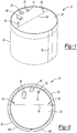
Figure 1 is a perspective view of the thermally insulated tank comprising the preferred embodiment of the present technology; -
Figure 2 is a top plan view of the thermally insulated tank with the lid in place; -
Figure 3 is a perspective view of an insulating panel comprising the preferred embodiment of the present technology; -
Figure 4 is a side elevation view of the insulating panel ofFIG. 3 comprising the preferred embodiment insulated storage tank of the present technology; -
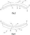
Figure 5 is a plan view as viewed from the top of the insulating panel of the present technology; -
Figure 6 is a plan view as viewed from the bottom of the insulating panel of the present technology; -
Figure 7 is a plan view of the bottom of the insulated storage tank comprising the preferred embodiment insulated storage tank of the present technology; -
Figure 8 is a cross-section view of the insulated storage tank comprising the preferred embodiment insulated storage tank of the present technology; -
Figure 9 is a drawing depicting the steps operable to assemble the insulated storage tank of the present technology; and -
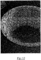
Figure 10 is a photograph of the insulating panels arranged in a cylindrical fashion prior to circumferential application of the outer support jacket around the insulating panels. - Corresponding reference numerals indicate corresponding parts throughout the several views of the drawings.
- The following description is merely exemplary in nature and is not intended to limit the present disclosure, application, or uses. It should be understood that throughout the drawings, corresponding reference numerals indicate like or corresponding parts and features.
- Example embodiments are provided so that this disclosure will be thorough, and will fully convey the scope to those who are skilled in the art. Numerous specific details are set forth such as examples of specific components, devices, and methods, to provide a thorough understanding of embodiments of the present disclosure. It will be apparent to those skilled in the art that specific details need not be employed, that example embodiments may be embodied in many different forms and that neither should be construed to limit the scope of the disclosure. In some example embodiments, well-known processes, well-known device structures, and well-known technologies are not described in detail.
- The terminology used herein is for the purpose of describing particular example embodiments only and is not intended to be limiting. As used herein, the singular forms "a", "an" and "the" may be intended to include the plural forms as well, unless the context clearly indicates otherwise. The terms "comprises," "comprising," "including," and "having," are inclusive and therefore specify the presence of stated features, integers, steps, operations, elements, and/or components, but do not preclude the presence or addition of one or more other features, integers, steps, operations, elements, components, and/or groups thereof. The method steps, processes, and operations described herein are not to be construed as necessarily requiring their performance in the particular order discussed or illustrated, unless specifically identified as an order of performance. It is also to be understood that additional or alternative steps may be employed.
- When an element or layer is referred to as being "on", "engaged to", "connected to" or "coupled to" another element or layer, it may be directly on, engaged, connected or coupled to the other element or layer, or intervening elements or layers may be present. In contrast, when an element is referred to as being "directly on," "directly engaged to", "directly connected to" or "directly coupled to" another element or layer, there may be no intervening elements or layers present. Other words used to describe the relationship between elements should be interpreted in a like fashion (e.g., "between" versus "directly between," "adjacent" versus "directly adjacent," etc.). As used herein, the term "and/or" includes any and all combinations of one or more of the associated listed items.
- Although the terms first, second, third, etc. may be used herein to describe various elements, components, regions, layers and/or sections, these elements, components, regions, layers and/or sections should not be limited by these terms. These terms may be only used to distinguish one element, component, region, layer or section from another region, layer or section. Terms such as "first," "second," and other numerical terms when used herein do not imply a sequence or order unless clearly indicated by the context. Thus, a first element, component, region, layer or section discussed below could be termed a second element, component, region, layer or section without departing from the teachings of the example embodiments.
- Spatially relative terms, such as "inner," "outer," "beneath", "below", "lower", "above", "upper" and the like, may be used herein for ease of description to describe one element or feature's relationship to another element(s) or feature(s) as illustrated in the figures. Spatially relative terms may be intended to encompass different orientations of the device in use or operation in addition to the orientation depicted in the figures. For example, if the device in the figures is turned over, elements described as "below" or "beneath" other elements or features would then be oriented "above" the other elements or features. Thus, the example term "below" can encompass both an orientation of above and below. The device may be otherwise oriented (rotated 90 degrees or at other orientations) and the spatially relative descriptors used herein interpreted accordingly.
- Referring now to the figures, particularly
Figures 1 and 2 , the preferred embodiment of the present technology comprising aninsulated storage tank 10 is shown. Theinsulated storage tank 10 comprises anouter support jacket 30, a plurality of insulatingpanels 100 in proximate contact withouter support jacket 30, aninner liner 400 which conforms to the interior cavity of the thermally insulatedtank 10 and an insulatinglid 20 covering the circular opening to theinsulated storage tank 10. Theinsulated storage tank 10 comprises a generally cylindrical-shape. The thinouter support jacket 30 surrounds the exterior arcuate surface of insulatingpanels 100 shown inFigure 2 . Theouter support jacket 10 provides structural rigidity and assists insulatingpanels 100 from collapsing or being forced apart.Outer support jacket 30 has a length that is generally slightly longer than the circumference of theinsulated storage tank 10. Theouter support jacket 30 has a height that is typically the same height ofinsulated storage tank 10. Theouter support jacket 30 can be made from any structurally resilient polymer, plastic, metal or wood, including for example thermoplastic polyolefin (TPO) materials commercially available as SEQUEL E3000 sold by Solvay Engineered Polymers Inc. (Auburn Hills, MI, USA). - In some embodiments the
outer support jacket 30 can have a width ranging from about 0.1 mm about 10 mm wide, or from about 1 mm to about 10 mm, or from about 2 mm to about 10 mm, or from about 0.1 mm to about 9 mm, or from about 0.1 mm to about 7 mm, or from about 0.1 mm to about 5 mm. The ends 35 of theouter support jacket 30 can be overlaid and glued together around the insulatingpanels 100 as shown inFigure 1 . - In some embodiments, the
insulated storage tank 10 includes an insulatinglid 20. Insulatinglid 20 can be made from any generally known insulation material including expanded polypropylene, thermosetting plastic foams, thermoplastic polyolefins, fiberglass, expanded perlite, wood, metals and any material that is capable of retaining the heat or cold in the liquids within theinsulated storage tank 10. Foam is preferably used because of the superior heat transfer properties provided by foam materials, relative ease of manufacture and it's lightweight. As shown inFigures 1 and 2 , the insulatinglid 20 can be apportioned along amidline 80 in two sections to allow the opening and removal of one half of the lid while keeping the other half in place. - The insulating
lid 20 can optionally house, support and integrate a variety of mechanical and electrical components that provide diagnostic and operational functionality to theinsulated storage tank 10. For example, insulatinglid 20 can be mounted with a plumbing board to provide all of the hydraulic operational requirements of the tank, for example, liquid input and output and sampling.Control unit 60 can also include a variety of mechanical and electrical components such as logic boards, relays, microprocessors and the like to send and receive electrical signals to and from a variety of mechanical and electrical components, for example, pumps and sensors. A variety of sensors can be included and mounted onto insulatinglid 20, for example,water level sensor 75 mounted to the lid with the aid of aseal 70.Water level sensor 75 can be free-standing or can be integrated withcontrol unit 60 and a pump (not shown) to determine the level of liquid in theinsulated storage tank 10. Upon liquid volume loss in theinsulated storage tank 10,liquid level sensor 75 can detect the deficiency and send a signal to controlunit 60 to activate a pump to fill the tank with more liquid.Temperature sensor 65 can also be integrated withcontrol unit 60 and measure the temperature of the liquid in theinsulated storage tank 10. - If the liquid in the
insulated storage tank 10 falls below a predetermined threshold,temperature sensor 65 can send a signal to a valve (not shown) to reduce the volume of liquid being recirculated on the roof of a residence from entering into theinsulated storage tank 10. Alternatively, thetemperature sensor 65 can alert the system if the liquid in theinsulated storage tank 10 rises above a predetermined threshold. In such a case, thetemperature sensor 65 can send a signal to a pump (not shown) to increase the flow of a secondary liquid being circulated in a heat exchanger (not shown) which is placed in theinsulated storage tank 10 to extract heat from the liquid in theinsulated storage tank 10. In addition,liquid inlet 50 andliquid outlet 55 can be used to add materials into theinsulated storage tank 10, or to remove materials, including liquids, within theinsulated storage tank 10. Generally, insulatinglid 20 has a diameter that is slightly larger than theinternal diameter 500 shown inFigure 8 . The thickness of insulatinglid 20 can vary and is not critical. However, for aesthetic appeal, the exterior surface of the insulatinglid 20 can be generally flush with thehorizontal rim surface 110 of the insulatingpanels 100 shown in greater detail inFigure 3 . - Referring now to
Figures 3-6 and8 -10 , theinsulated storage tank 10 also includes a plurality of vertical insulatingpanels 100. In some embodiments, the insulatingpanels 100 are the cylindrical side walls of theinsulated storage tank 10 that supports the insulatinglid 20. In use the insulatinglid 20 is placed on thelid resting shelf 160. With reference toFigure 3 , illustrating the insulatingpanel 100 in perspective view, the insulatingpanel 100 has a rim and ahorizontal rim surface 110, the rim also includes arim side wall 170 andlid resting shelf 160. Insulatingpanel 100 has a leadingedge contact surface 140 and a trailingedge contact surface 150. The insulatingfloor 25 is slotted into the recess formed by floor contact wall180 andfloor support shelf 185. When the complete cylinder is formed by aligning all of the required insulatingpanels 100 as shown inFigures 9 and10 along with the insulatingfloor 25, theinner liner 400 can be placed in the void created by the arrangement of the insulatingpanels 100 and insulatingfloor 25 as shown inFigure 9 . Theinner liner 400 rests against and is supported by interiorarcuate surface 130 of insulatingpanel 100. - Insulating
panel 100 has a leadingedge contact surface 140 forms aleading edge apex 142 with a trailing edge offset 210. The placement of the leadingedge contact surface 140 of one insulatingpanel 100 in direct contact with the trailingedge contact surface 150 of the nextinsulating panel 100 in succession (in a clock wise fashion) has been surprisingly found to provide substantial resistance to radial movement of the insulating panels due to the hydrostatic force created by liquid. All of the insulatingpanels 100 can be connected with the use of a clasping mechanism placed on the exteriorarcuate surface 120. Alternatively, the leadingedge contact surface 140 and the trailingedge contact surface 150 of insulatingpanels 100 can each have male and female interlocking structure that can approximate the twocontact surfaces panel 100 can all be clasped or structurally held in position by placing anouter support jacket 30 around the exteriorarcuate surface 120 as shown inFigures 1 and9 . - It has been determined that for a 60 inch outer diameter/350 gallon insulated
storage tank 10, the pressure exerted on a 1 mm thick TPOouter support jacket 30 after theinsulated storage tank 10 has been fully assembled having an insulating panel thickness of 4.4 inches, and aninner liner 400 storing 330 gal of water, 1 m high column of water, inner tank radius of 25.6 inches) is approximately 1084 psi which is well within its tensile yield of 3100 psi. For a 2000 gallon tank with a 2 mm thick TPO outer support jacket using the same column water height but an inner radius of 61.1 inches, the stress on theouter support jacket 30 is approximately 1184.5 psi and is also well within its tensile yield of 3100 psi. - The insulating
panel 100 can also be made of any suitable modular material as described above for the insulatinglid 20. These can include expanded polypropylene, thermosetting plastic foams, thermoplastic polyolefins, fiberglass, expanded perlite, wood, metals and any material that is capable of retaining the heat or cold in the liquids within theinsulated storage tank 10. Foam is preferably used because of the superior heat transfer properties provided by foam materials, relative ease of manufacture and is lightweight. The dimensions of the insulatingpanel 100 can vary according to the size of theinsulated storage tank 10 needed. For example, for a 330 gallon insulated storage tank, 5 insulatingpanels 100 can be used form a complete cylinder. For a 330 gallon insulatedstorage tank 10, each insulatingpanel 100 can measure approximately 47 inches in height, an arcuate length of 34.5 inches and a width of approximately 4 inches. In some embodiments, the number of insulatingpanels 100 used to form theinsulated storage tank 10 can vary, preferably there are 5 insulatingpanel 100 perinsulated storage tank 10. - In some embodiments of the present technology, the
insulated storage tank 10 can also optionally have an insulatingfloor 25. While not essential to the practice of the present technology, an insulatingfloor 25 can be used with the bottom cutout in the insulatingpanel 100 to provide a unified structure that is configured to resist the hydrostatic stresses imposed on theinsulated storage tank 100 walls. As illustrated inFigures 7 and 8 , the insulatingfloor 25 can be made from any insulation material as described above for the insulatingpanel 100. Insulatingfloor 25 can be a single piece of insulation or it can be made from two halves divided by theline 82 as shown inFigure 7 . - Best shown in
Figure 8 , theinner liner 400 can be constructed from any synthetic or natural material that is capable of withstanding liquids having temperatures ranging from about 0°C to about 250°C, preferably from about 4°C to about 190°C. In some embodiments, theinner liner 400 can be constructed of a synthetic plastic material, polymer material or thermoplastic materials capable of withstanding liquid temperatures ranging from about 0°C to about 250°C. In some embodiments, theinner liner 400 can be made from a poly vinyl chloride material. - With reference now to
Figures 9 and10 , theinsulated storage tank 10 can be prepacked on a pellet saving transportation costs and freight charges. The small footprint of the delivery package containing the modular insulated storage tank also affords vastly improved maneuverability and locations for installation. As shown inFigure 9 , the modular parts of theinsulated storage tank 10 can be easily assembled by first preparing the insulatingfloor 25. As previously noted, the insulating floor is not essential to the invention. However, it is preferred to other forms of insulation flooring. If the insulating panels are fitted withfloor contact walls 180 andfloor support shelves 185, then the insulatingpanel 100 can be slotted into position adjacent and on top of insulatingfloor 25. Then all of the insulatingpanels 100 are placed around the floor, ensuring that the leadingedge contact surface 140 and a trailingedge contact surface 150 of insulatingpanels 100 are abutting one another. Once the insulatingpanels 100 have been positioned around the insulatingfloor 25 the next step is to place theinner liner 400 into the cavity of theinsulated storage tank 10 and leave an overhang ofinner liner 400 extend over thehorizontal rim surface 110 of the insulatingpanels 100. The last step can include placing anouter support jacket 30 around the exterior arcuate surface of all of the insulatingpanels 100 and joining the ends of theouter support jacket 30 leaving a joint 35 as shown inFigure 1 . - The present technology affords a simple manner in which to prepare on site an insulated storage tank having liquid capacities ranging from 50 gallons to 5,000 gallons. The insulated storage tank has many used for storing both hot and cold liquids.
- In a preferred embodiment, the hot liquid stored in the
insulated storage tank 10 can include liquids (e.g. water), that are recirculated through a solar thermal capture device, for example, the Power Panel Solar/Thermal capture device disclosed inInternational Application PCT/US2008/078822 , filed 10/3/2008, the disclosure of which is incorporated herein in its entirety. The stored hot liquids (e.g. water) recirculating through said Power Panel Solar/Thermal capture device can reach temperatures ranging from 75 - 120°C. The stored hot liquid in theinsulated storage tank 10 of the present technology can be used to heat a secondary potable water source (for example a domestic home water source) with the use of heat exchangers placed in theinsulated storage tank 10. Similarly, heat exchangers placed in insulated storage tanks storing compressed liquids such as carbon dioxide can be used to cool a secondary liquid source for residential or commercial cooling. The rate of recirculation through the solar/thermal energy capture device and passage into theinsulated storage tank 10 can be automated to maintain a set temperature within theinsulated storage tank 10. - The embodiments and the examples described herein are exemplary and not intended to be limiting in describing the full scope of compositions and methods of the present technology. Equivalent changes, modifications and variations of some embodiments, materials, compositions and methods can be made within the scope of the present technology, with substantially similar results.
Claims (14)
- An insulated storage tank (10), comprising:a plurality of insulating panels (100) disposed in a circumferential pattern, the insulating panels (100) each in contact with two other panels forming a cylindrical wall,an inner liner (400) disposed within the cylindrical wall to be filled with a hot or cold liquid and conforming in shape to the insulating panels (100),characterized in thatindividual ones of the insulating panels (100) each including a leading edge contact surface (140) forming a leading edge apex (142) and a trailing edge offset (210), and an oppositely located trailing edge contact surface (150), wherein the leading edge contact surface (140) of one of the insulating panels (100) is placed in direct contact with the trailing edge contact surface (150) of a next successive one of the insulating panels (100);a single outer support jacket (30) surrounding an exterior arcuate surface (120) of the cylindrical wall of insulating panels (100).
- The insulated storage tank (10) of Claim 1, further comprising:a lid resting shelf (160) created on an interior facing rim side wall (170) of the cylindrical wall; anda substantially circular insulated tank lid (20) disposed on the lid resting shelf (160) thereby sealing the contents of the insulated storage tank (10).
- The insulated storage tank (10) of Claim 2, further comprising:a control unit (60) disposed on the tank lid (20);a water level sensor (75) disposed on the tank lid (20) and integrated with the control unit (60), the water level sensor (75) operating to measure a liquid level within the storage tank (10) and create a signal used by the controlunit (60) to control a flow of the liquid into and out of the storage tank (10) to vary the liquid level; anda temperature sensor (65) disposed on the tank lid (20) and integrated with the control unit (60), the temperature sensor (65) operating to measure a temperature of the liquid within the storage tank (10) and create a signal used by the control unit (60) to control a flow of the liquid into and out of the storage tank (10) to vary the temperature of the liquid.
- The insulated storage tank (10) of Claim 1, wherein the inner liner (400) is constructed from a polymeric material capable of retaining a liquid at a temperature ranging from approximately zero degrees Centigrade to approximately 250 degrees Centigrade inclusive.
- The insulated storage tank (10) of Claim 1, wherein the outer support jacket (30) has a length greater than an outer circumference of the cylindrical wall of the insulated storage tank (10) and a height substantially equal to a height of the cylindrical wall.
- The insulated storage tank (10) of Claim 1, wherein the outer support jacket (30) comprises a polymeric material having a width ranging from approximately 0.1 mm to 10 mm inclusive, the outer support jacket (30) having ends (35) overlapped with each other and fixedly connected to each other.
- The insulated storage tank (10) of Claim 1, further comprising a substantially circular insulated tank lid (20) disposed on the cylindrical wall and in contact with the inner liner (400) to seal the liquid contained in the insulated storage tank (10).
- The insulated storage tank (10) of Claim 7, further comprising:a control unit (60) disposed on the tank lid (20);a water level sensor (75) disposed on the tank lid (20) and integrated with the control unit (60); anda temperature sensor (65) disposed on the tank lid (20) and integrated with the control unit (60);wherein the tank lid (20) is divisible into first and second portions, each of the control unit (60), the water level sensor (75) and the temperature sensor (65) being disposed a same one of the first or second portion such that the opposite one of the first or second portions can be opened without interfering with operation of any of the control unit (60), the water level sensor (75) or the temperature sensor (65).
- The insulated storage tank (10) of Claim 8, wherein the water level sensor (75) operates to measure a liquid level within the storage tank (10) and create a signal used by the control unit (60) to control a flow of the liquid into and out of the storage tank (10) to vary the liquid level; and wherein the temperature sensor (65) operates to measure a temperature of the liquid within the storage tank (10) and create a signal used by the control unit (60) to control a flow of the liquid into and out of the storage tank (10) to vary the temperature of the liquid.
- The insulated storage tank (10) of Claim 1, further comprising an insulating floor (25) slotted to be received into a recess formed by a floor contact wall (180) and a floor support shelf (185) created in the cylindrical wall, wherein the inner liner (400) is supported on the insulating floor (25).
- The insulated storage tank (10) of Claim 1, further comprising:a lid resting shelf (160) created on an interior facing rim side wall (170) of the cylindrical wall, wherein the inner liner (400) is in contact with the lid resting shelf (160) and the tank lid (20) is disposed on the inner liner (400) and supported by the lid resting shelf (160);wherein a quantity of five of the insulating panels (100) are joined to create at least first and second liquid capacities of the storage tank (10), an arcuate length of each of the insulating panels (100) being varied to vary an inner tank radius to differentiate the first and second liquid capacities.
- A method for constructing an insulated storage tank (10), the storage tank (10) including a plurality of insulating panels (100), individual ones of the insulating panels (100) each including a leading edge contact surface (140) forming a leading edge apex (142) and a trailing edge offset (210), and an oppositely located trailing edge contact surface (150), an inner liner (400), an insulating lid (20), an insulating floor (25); and an outer support jacket (30), the method comprising:creating floor contact walls (180) and floor support shelves in each of the insulating panels (100);slotting the insulating panels (100) into position adjacent and on top of the insulating floor (25) such that all of the insulating panels (100) are placed around the floor having the leading edge contact surface (140) and the trailing edge contact surface (150) of proximate insulating panels (100) abutting one another creating a cylindrical wall;inserting the inner liner (400) into a cavity created by the insulating panels (100) such that the inner liner (400) covers the insulating floor (25) and lines an inner circumference of the insulating panels (100); andplacing the outer support jacket (30) around an exterior arcuate surface (120) of all of the insulating panels (100).
- The method of Claim 12, further comprising:creating an overhang (402) of the inner liner (400) extending over a horizontal rim surface (110) of the insulating panels (100) during the placing step,forming a lid resting shelf (160) on an interior facing rim side wall (170) of the cylindrical wall during the creating step; anddisposing the tank lid (20) on the inner liner (400) extending over the horizontal rim surface (110) of the insulating panels (100) and supported by the lid resting shelf (160).
- The method of Claim 12, further comprising joining opposite ends (35) of the outer support jacket (30) to creating a joint (35).
Applications Claiming Priority (2)
| Application Number | Priority Date | Filing Date | Title |
|---|---|---|---|
| US20827509P | 2009-02-20 | 2009-02-20 | |
| PCT/US2010/024758 WO2010096667A2 (en) | 2009-02-20 | 2010-02-19 | Insulated storage tank |
Publications (3)
| Publication Number | Publication Date |
|---|---|
| EP2398719A2 EP2398719A2 (en) | 2011-12-28 |
| EP2398719A4 EP2398719A4 (en) | 2015-02-18 |
| EP2398719B1 true EP2398719B1 (en) | 2017-01-25 |
Family
ID=42630064
Family Applications (1)
| Application Number | Title | Priority Date | Filing Date |
|---|---|---|---|
| EP10744367.3A Active EP2398719B1 (en) | 2009-02-20 | 2010-02-19 | Insulated storage tank |
Country Status (7)
| Country | Link |
|---|---|
| US (1) | US8381939B2 (en) |
| EP (1) | EP2398719B1 (en) |
| JP (1) | JP5686746B2 (en) |
| KR (1) | KR101617817B1 (en) |
| CN (1) | CN102395517B (en) |
| CA (1) | CA2752673C (en) |
| WO (1) | WO2010096667A2 (en) |
Families Citing this family (26)
| Publication number | Priority date | Publication date | Assignee | Title |
|---|---|---|---|---|
| US20120244299A1 (en) * | 2011-03-23 | 2012-09-27 | Carlos Colon | Insulation apparatus |
| CN104854002B (en) * | 2012-12-12 | 2018-03-27 | 绿源水私人有限公司 | Modular Storage Tank |
| US10253991B2 (en) | 2013-04-02 | 2019-04-09 | Tigi Ltd. | In-line heated solar thermal storage collector |
| CN104229306A (en) * | 2013-12-02 | 2014-12-24 | 鸿富锦精密工业(武汉)有限公司 | Accommodating case |
| JP2015190484A (en) * | 2014-03-27 | 2015-11-02 | 株式会社フォームテック | Heat insulation panel for covering spherical curved surface of liquefied gas tank |
| WO2015147678A1 (en) | 2014-03-28 | 2015-10-01 | Открытое акционерное общество "Акционерная компания по транспорту нефти "ТРАНСНЕФТЬ" | Method for thermally insulating reservoirs |
| CA2942865C (en) | 2014-03-28 | 2021-07-13 | Public Joint Stock Company "Transneft" | Heat insulated tank |
| AP2017009714A0 (en) * | 2014-08-08 | 2017-02-28 | Sirac Southern Africa Pty Ltd | A thermal storage tank |
| CN105644987B (en) * | 2014-12-03 | 2018-02-02 | 江南造船(集团)有限责任公司 | The installation method of A type independent liquid cargo tank hydrops slot insulation |
| WO2017091761A1 (en) | 2015-11-25 | 2017-06-01 | Yeti Coolers, Llc | Insulating container having vacuum insulated panels and method |
| USD821155S1 (en) | 2017-05-16 | 2018-06-26 | Yeti Coolers, Llc | Insulating device |
| USD821156S1 (en) | 2017-05-16 | 2018-06-26 | Yeti Coolers, Llc | Insulating device |
| USD820647S1 (en) | 2017-05-16 | 2018-06-19 | Yeti Coolers, Llc | Insulating device |
| USD820648S1 (en) | 2017-05-16 | 2018-06-19 | Yeti Coolers, Llc | Insulating device |
| USD821157S1 (en) | 2017-05-16 | 2018-06-26 | Yeti Coolers, Llc | Insulating device |
| USD821824S1 (en) | 2017-05-16 | 2018-07-03 | Yeti Coolers, Llc | Insulating device |
| EP4061745B1 (en) * | 2019-11-21 | 2025-07-02 | Poly-Line Pte Ltd | Sectional panel tank, method of making a side wall for a sectional panel tank |
| NL2024361B1 (en) * | 2019-12-02 | 2021-08-31 | Summerheat Group B V | Thermal energy storage |
| EP4070025A2 (en) * | 2019-12-02 | 2022-10-12 | Summerheat Group B.V. | Thermal energy storage |
| US12388396B2 (en) * | 2020-01-16 | 2025-08-12 | Moshe Zeidman | Windows for producing electricity from solar energy |
| CN114275393B (en) * | 2020-09-27 | 2023-02-28 | 湖南梨树园涂料有限公司 | Storage device is used in water proof coating production |
| AU2021401538B2 (en) | 2020-12-17 | 2025-05-29 | Genesis Systems Llc | Atmospheric water generation systems and methods |
| IL305236A (en) * | 2021-03-09 | 2023-10-01 | Genesis Systems Llc | Atmospheric water generation systems and methods utilizing membrane-based water extraction |
| CN113525948B (en) * | 2021-06-07 | 2023-09-19 | 上海电气集团股份有限公司 | A three-dimensional array circuit detection system and method for molten salt storage tank leakage |
| CN115434212B (en) * | 2022-09-26 | 2023-11-24 | 中国建筑第五工程局有限公司 | But town road is with cyclic utilization's pitch regeneration facility |
| KR102868037B1 (en) * | 2023-04-27 | 2025-10-13 | 주식회사 윈드밸리 | Anti-Condensation Oil Tank |
Family Cites Families (28)
| Publication number | Priority date | Publication date | Assignee | Title |
|---|---|---|---|---|
| US3010599A (en) * | 1958-07-22 | 1961-11-28 | Armstrong Cork Co | Thermally insulated tank structure |
| US3378162A (en) * | 1965-10-01 | 1968-04-16 | B & B Engineering Company Inc | Insulated tanks |
| US3456835A (en) * | 1968-04-12 | 1969-07-22 | Emil G Marcmann | Thermally insulated tank structure |
| US3559835A (en) * | 1968-07-17 | 1971-02-02 | Chicago Bridge & Iron Co | Insulated storage tank with insulation restrained against settling because of metal contraction |
| JPS51153822U (en) * | 1975-06-02 | 1976-12-08 | ||
| DE2855911A1 (en) * | 1978-12-23 | 1980-07-10 | Isopag Ag | THERMO-INSULATED HEAT STORAGE |
| US4296799A (en) * | 1979-05-29 | 1981-10-27 | Steele Richard S | Solar water tank and method of making same |
| US4407268A (en) * | 1980-04-03 | 1983-10-04 | Jardin Albert C | Solar furnace |
| US4314602A (en) * | 1980-08-25 | 1982-02-09 | Solar Unlimited, Inc. | Knock-down heat storage tank |
| FR2500580A1 (en) * | 1981-02-20 | 1982-08-27 | Technigaz | STORAGE TANK FOR LIQUID CRYOGENIC GASES SUCH AS HYDROGEN IN PARTICULAR |
| US4368819A (en) * | 1981-03-16 | 1983-01-18 | Harvey Durham | Insulated container and closure |
| US4498602A (en) * | 1983-12-08 | 1985-02-12 | Chicago Bridge & Iron Company | Resilient blanket with integral high strength facing and method of making same |
| US4907569A (en) * | 1989-01-05 | 1990-03-13 | A.O. Smith Corporation | Water heater with skirt ring dam |
| JPH02140276U (en) * | 1989-04-26 | 1990-11-22 | ||
| DE9014298U1 (en) * | 1990-10-15 | 1990-12-20 | Widhalm, Raimund, St. Valentin | Insulation of containers, boilers, tanks, etc. |
| IT1260240B (en) * | 1992-12-23 | 1996-04-02 | INSULATION SYSTEM. | |
| JPH0741192U (en) * | 1993-12-24 | 1995-07-21 | ニチアス株式会社 | Metal coated heat insulating material |
| DE4438970A1 (en) | 1994-10-31 | 1996-05-02 | Consolar Energiespeicher Und R | Thermal accumulator of modular construction with a single, sectional thermal insulation jacket |
| DE29518110U1 (en) | 1995-11-15 | 1996-11-28 | Achenbach GmbH & Co. KG, 57548 Kirchen | Heat insulating body jacket |
| JP3550239B2 (en) * | 1995-12-28 | 2004-08-04 | 明星工業株式会社 | Insulation panel |
| DE29600455U1 (en) * | 1996-01-12 | 1996-02-29 | Foliplast GmbH, 57520 Niederdreisbach | Thermal insulation element for the body, especially for hot water tanks |
| US6938478B2 (en) * | 2002-11-14 | 2005-09-06 | Herman Diaz Arias | Impedance level meter for liquids in tanks |
| DE102004026396B4 (en) * | 2004-05-29 | 2007-10-31 | Itw Automotive Products Gmbh & Co. Kg | Device for measuring the level height and / or the temperature in a container |
| JP2006145024A (en) * | 2004-10-19 | 2006-06-08 | Taiyo Nippon Sanso Corp | Insulated container and liquid level gauge for insulated container |
| WO2006133357A2 (en) * | 2005-06-08 | 2006-12-14 | Lumenite Control Technology Inc. | Self-calibrating liquid level transmitter |
| JP2006077994A (en) * | 2005-12-02 | 2006-03-23 | Kajima Corp | Installation method of thermal resistance mitigation material for a breakwater integrated low temperature tank and a breakwater integrated low temperature tank |
| US8152367B2 (en) * | 2007-05-04 | 2012-04-10 | Sealed Air Corporation (Us) | Insulated container having a temperature monitoring device |
| FI20090029A0 (en) * | 2009-02-02 | 2009-02-02 | Northern Tanker Company Oy | Internal heat insulation of bitumen and oil tanks |
-
2010
- 2010-02-19 CA CA2752673A patent/CA2752673C/en active Active
- 2010-02-19 WO PCT/US2010/024758 patent/WO2010096667A2/en not_active Ceased
- 2010-02-19 EP EP10744367.3A patent/EP2398719B1/en active Active
- 2010-02-19 KR KR1020117021661A patent/KR101617817B1/en active Active
- 2010-02-19 CN CN2010800170163A patent/CN102395517B/en active Active
- 2010-02-19 JP JP2011551253A patent/JP5686746B2/en active Active
- 2010-02-19 US US12/709,334 patent/US8381939B2/en active Active
Non-Patent Citations (1)
| Title |
|---|
| None * |
Also Published As
| Publication number | Publication date |
|---|---|
| JP5686746B2 (en) | 2015-03-18 |
| US8381939B2 (en) | 2013-02-26 |
| US20100213201A1 (en) | 2010-08-26 |
| CA2752673A1 (en) | 2010-08-26 |
| WO2010096667A3 (en) | 2010-12-02 |
| EP2398719A4 (en) | 2015-02-18 |
| KR20110139227A (en) | 2011-12-28 |
| JP2012518579A (en) | 2012-08-16 |
| CN102395517B (en) | 2013-06-12 |
| EP2398719A2 (en) | 2011-12-28 |
| CN102395517A (en) | 2012-03-28 |
| KR101617817B1 (en) | 2016-05-03 |
| CA2752673C (en) | 2015-11-17 |
| WO2010096667A2 (en) | 2010-08-26 |
Similar Documents
| Publication | Publication Date | Title |
|---|---|---|
| US8381939B2 (en) | Insulated storage tank | |
| US5941238A (en) | Heat storage vessels for use with heat pumps and solar panels | |
| CN102713281B (en) | Energy Systems for Dwelling Support | |
| US8353286B2 (en) | Solar water heater and method | |
| CN102235759B (en) | Thermally-driven liquid self-circulation method and device and liquid self-circulation system applying devices | |
| EP2914919B1 (en) | Method for operating an arrangement for storing thermal energy | |
| US20120132195A1 (en) | Convection Driven Two-Component Solar Water Heater Using All-Glass Evacuated Tubes with a Heat Separator | |
| US20160036379A1 (en) | Hybrid solar thermal and photovoltaic system with termal energy cature subsystem | |
| CN103229002A (en) | Solar water heater | |
| US11549693B2 (en) | Hot water tank | |
| KR20130106765A (en) | Heat driven self-circulating fluid heating and storage tanks and systems | |
| CN101216216B (en) | Architecture integral type wall-type solar heat-collector | |
| EA005300B1 (en) | Solar station of hot water supply and solar heat collector therefor | |
| KR100994888B1 (en) | Warm water tank for durability against high temperature | |
| WO2010007103A1 (en) | Roofing panel and roof structure | |
| MX2013001404A (en) | Unit for harnessing solar power. | |
| CN104061695B (en) | One is superthermal leads the two inner bag solar engineering double-row heat collector of U-tube | |
| CN203880970U (en) | Flat plate type solar water heater | |
| CN2535727Y (en) | Vacuum tube split pressure-bearing type solar water-heater | |
| WO2011062661A2 (en) | Collapsible hot water storage tank | |
| CN101871438A (en) | Solar heat water low-temperature generating system | |
| CN202853150U (en) | Inlay and flat type all-green building integration solar water heater | |
| STEPHEN et al. | DESIGN AND FABRICATION OF A SOLAR WATER HEATING SYSTEM | |
| Hackleman | 7Solar Water Heating System Designs | |
| KR20130106766A (en) | Fluid heating and storage tank and system |
Legal Events
| Date | Code | Title | Description |
|---|---|---|---|
| PUAI | Public reference made under article 153(3) epc to a published international application that has entered the european phase |
Free format text: ORIGINAL CODE: 0009012 |
|
| 17P | Request for examination filed |
Effective date: 20110907 |
|
| AK | Designated contracting states |
Kind code of ref document: A2 Designated state(s): AT BE BG CH CY CZ DE DK EE ES FI FR GB GR HR HU IE IS IT LI LT LU LV MC MK MT NL NO PL PT RO SE SI SK SM TR |
|
| RAP1 | Party data changed (applicant data changed or rights of an application transferred) |
Owner name: POWER PANEL, INC. |
|
| DAX | Request for extension of the european patent (deleted) | ||
| A4 | Supplementary search report drawn up and despatched |
Effective date: 20150116 |
|
| RIC1 | Information provided on ipc code assigned before grant |
Ipc: B65D 90/06 20060101AFI20150112BHEP Ipc: B65D 90/04 20060101ALI20150112BHEP Ipc: E03B 11/00 20060101ALI20150112BHEP Ipc: B65D 88/06 20060101ALI20150112BHEP Ipc: F24H 1/18 20060101ALI20150112BHEP Ipc: F24J 2/34 20060101ALI20150112BHEP Ipc: B65D 90/48 20060101ALI20150112BHEP Ipc: F16L 59/02 20060101ALI20150112BHEP |
|
| 17Q | First examination report despatched |
Effective date: 20160119 |
|
| REG | Reference to a national code |
Ref country code: DE Ref legal event code: R079 Ref document number: 602010039794 Country of ref document: DE Free format text: PREVIOUS MAIN CLASS: B65D0090060000 Ipc: F28D0020000000 |
|
| GRAP | Despatch of communication of intention to grant a patent |
Free format text: ORIGINAL CODE: EPIDOSNIGR1 |
|
| RIC1 | Information provided on ipc code assigned before grant |
Ipc: F24J 2/34 20060101ALI20160802BHEP Ipc: F24H 1/18 20060101ALI20160802BHEP Ipc: F16L 59/02 20060101ALI20160802BHEP Ipc: F28D 20/00 20060101AFI20160802BHEP |
|
| INTG | Intention to grant announced |
Effective date: 20160824 |
|
| GRAS | Grant fee paid |
Free format text: ORIGINAL CODE: EPIDOSNIGR3 |
|
| GRAA | (expected) grant |
Free format text: ORIGINAL CODE: 0009210 |
|
| AK | Designated contracting states |
Kind code of ref document: B1 Designated state(s): AT BE BG CH CY CZ DE DK EE ES FI FR GB GR HR HU IE IS IT LI LT LU LV MC MK MT NL NO PL PT RO SE SI SK SM TR |
|
| REG | Reference to a national code |
Ref country code: GB Ref legal event code: FG4D |
|
| REG | Reference to a national code |
Ref country code: CH Ref legal event code: EP |
|
| REG | Reference to a national code |
Ref country code: AT Ref legal event code: REF Ref document number: 864389 Country of ref document: AT Kind code of ref document: T Effective date: 20170215 |
|
| REG | Reference to a national code |
Ref country code: IE Ref legal event code: FG4D |
|
| REG | Reference to a national code |
Ref country code: FR Ref legal event code: PLFP Year of fee payment: 8 |
|
| REG | Reference to a national code |
Ref country code: DE Ref legal event code: R096 Ref document number: 602010039794 Country of ref document: DE |
|
| REG | Reference to a national code |
Ref country code: LT Ref legal event code: MG4D |
|
| PG25 | Lapsed in a contracting state [announced via postgrant information from national office to epo] |
Ref country code: BE Free format text: LAPSE BECAUSE OF NON-PAYMENT OF DUE FEES Effective date: 20170228 |
|
| REG | Reference to a national code |
Ref country code: NL Ref legal event code: MP Effective date: 20170125 |
|
| REG | Reference to a national code |
Ref country code: AT Ref legal event code: MK05 Ref document number: 864389 Country of ref document: AT Kind code of ref document: T Effective date: 20170125 |
|
| PG25 | Lapsed in a contracting state [announced via postgrant information from national office to epo] |
Ref country code: NL Free format text: LAPSE BECAUSE OF FAILURE TO SUBMIT A TRANSLATION OF THE DESCRIPTION OR TO PAY THE FEE WITHIN THE PRESCRIBED TIME-LIMIT Effective date: 20170125 |
|
| PG25 | Lapsed in a contracting state [announced via postgrant information from national office to epo] |
Ref country code: NO Free format text: LAPSE BECAUSE OF FAILURE TO SUBMIT A TRANSLATION OF THE DESCRIPTION OR TO PAY THE FEE WITHIN THE PRESCRIBED TIME-LIMIT Effective date: 20170425 Ref country code: LT Free format text: LAPSE BECAUSE OF FAILURE TO SUBMIT A TRANSLATION OF THE DESCRIPTION OR TO PAY THE FEE WITHIN THE PRESCRIBED TIME-LIMIT Effective date: 20170125 Ref country code: GR Free format text: LAPSE BECAUSE OF FAILURE TO SUBMIT A TRANSLATION OF THE DESCRIPTION OR TO PAY THE FEE WITHIN THE PRESCRIBED TIME-LIMIT Effective date: 20170426 Ref country code: HR Free format text: LAPSE BECAUSE OF FAILURE TO SUBMIT A TRANSLATION OF THE DESCRIPTION OR TO PAY THE FEE WITHIN THE PRESCRIBED TIME-LIMIT Effective date: 20170125 Ref country code: FI Free format text: LAPSE BECAUSE OF FAILURE TO SUBMIT A TRANSLATION OF THE DESCRIPTION OR TO PAY THE FEE WITHIN THE PRESCRIBED TIME-LIMIT Effective date: 20170125 Ref country code: IS Free format text: LAPSE BECAUSE OF FAILURE TO SUBMIT A TRANSLATION OF THE DESCRIPTION OR TO PAY THE FEE WITHIN THE PRESCRIBED TIME-LIMIT Effective date: 20170525 |
|
| PG25 | Lapsed in a contracting state [announced via postgrant information from national office to epo] |
Ref country code: AT Free format text: LAPSE BECAUSE OF FAILURE TO SUBMIT A TRANSLATION OF THE DESCRIPTION OR TO PAY THE FEE WITHIN THE PRESCRIBED TIME-LIMIT Effective date: 20170125 Ref country code: PL Free format text: LAPSE BECAUSE OF FAILURE TO SUBMIT A TRANSLATION OF THE DESCRIPTION OR TO PAY THE FEE WITHIN THE PRESCRIBED TIME-LIMIT Effective date: 20170125 Ref country code: LV Free format text: LAPSE BECAUSE OF FAILURE TO SUBMIT A TRANSLATION OF THE DESCRIPTION OR TO PAY THE FEE WITHIN THE PRESCRIBED TIME-LIMIT Effective date: 20170125 Ref country code: SE Free format text: LAPSE BECAUSE OF FAILURE TO SUBMIT A TRANSLATION OF THE DESCRIPTION OR TO PAY THE FEE WITHIN THE PRESCRIBED TIME-LIMIT Effective date: 20170125 Ref country code: BG Free format text: LAPSE BECAUSE OF FAILURE TO SUBMIT A TRANSLATION OF THE DESCRIPTION OR TO PAY THE FEE WITHIN THE PRESCRIBED TIME-LIMIT Effective date: 20170425 Ref country code: PT Free format text: LAPSE BECAUSE OF FAILURE TO SUBMIT A TRANSLATION OF THE DESCRIPTION OR TO PAY THE FEE WITHIN THE PRESCRIBED TIME-LIMIT Effective date: 20170525 Ref country code: ES Free format text: LAPSE BECAUSE OF FAILURE TO SUBMIT A TRANSLATION OF THE DESCRIPTION OR TO PAY THE FEE WITHIN THE PRESCRIBED TIME-LIMIT Effective date: 20170125 |
|
| REG | Reference to a national code |
Ref country code: CH Ref legal event code: PL |
|
| REG | Reference to a national code |
Ref country code: DE Ref legal event code: R097 Ref document number: 602010039794 Country of ref document: DE |
|
| PG25 | Lapsed in a contracting state [announced via postgrant information from national office to epo] |
Ref country code: EE Free format text: LAPSE BECAUSE OF FAILURE TO SUBMIT A TRANSLATION OF THE DESCRIPTION OR TO PAY THE FEE WITHIN THE PRESCRIBED TIME-LIMIT Effective date: 20170125 Ref country code: CH Free format text: LAPSE BECAUSE OF NON-PAYMENT OF DUE FEES Effective date: 20170228 Ref country code: LI Free format text: LAPSE BECAUSE OF NON-PAYMENT OF DUE FEES Effective date: 20170228 Ref country code: RO Free format text: LAPSE BECAUSE OF FAILURE TO SUBMIT A TRANSLATION OF THE DESCRIPTION OR TO PAY THE FEE WITHIN THE PRESCRIBED TIME-LIMIT Effective date: 20170125 Ref country code: IT Free format text: LAPSE BECAUSE OF FAILURE TO SUBMIT A TRANSLATION OF THE DESCRIPTION OR TO PAY THE FEE WITHIN THE PRESCRIBED TIME-LIMIT Effective date: 20170125 Ref country code: CZ Free format text: LAPSE BECAUSE OF FAILURE TO SUBMIT A TRANSLATION OF THE DESCRIPTION OR TO PAY THE FEE WITHIN THE PRESCRIBED TIME-LIMIT Effective date: 20170125 Ref country code: SK Free format text: LAPSE BECAUSE OF FAILURE TO SUBMIT A TRANSLATION OF THE DESCRIPTION OR TO PAY THE FEE WITHIN THE PRESCRIBED TIME-LIMIT Effective date: 20170125 |
|
| REG | Reference to a national code |
Ref country code: IE Ref legal event code: MM4A |
|
| PG25 | Lapsed in a contracting state [announced via postgrant information from national office to epo] |
Ref country code: MC Free format text: LAPSE BECAUSE OF FAILURE TO SUBMIT A TRANSLATION OF THE DESCRIPTION OR TO PAY THE FEE WITHIN THE PRESCRIBED TIME-LIMIT Effective date: 20170125 Ref country code: SM Free format text: LAPSE BECAUSE OF FAILURE TO SUBMIT A TRANSLATION OF THE DESCRIPTION OR TO PAY THE FEE WITHIN THE PRESCRIBED TIME-LIMIT Effective date: 20170125 Ref country code: DK Free format text: LAPSE BECAUSE OF FAILURE TO SUBMIT A TRANSLATION OF THE DESCRIPTION OR TO PAY THE FEE WITHIN THE PRESCRIBED TIME-LIMIT Effective date: 20170125 |
|
| PLBE | No opposition filed within time limit |
Free format text: ORIGINAL CODE: 0009261 |
|
| STAA | Information on the status of an ep patent application or granted ep patent |
Free format text: STATUS: NO OPPOSITION FILED WITHIN TIME LIMIT |
|
| GBPC | Gb: european patent ceased through non-payment of renewal fee |
Effective date: 20170425 |
|
| PG25 | Lapsed in a contracting state [announced via postgrant information from national office to epo] |
Ref country code: LU Free format text: LAPSE BECAUSE OF NON-PAYMENT OF DUE FEES Effective date: 20170219 |
|
| 26N | No opposition filed |
Effective date: 20171026 |
|
| REG | Reference to a national code |
Ref country code: FR Ref legal event code: PLFP Year of fee payment: 9 Ref country code: BE Ref legal event code: MM Effective date: 20170228 |
|
| PG25 | Lapsed in a contracting state [announced via postgrant information from national office to epo] |
Ref country code: SI Free format text: LAPSE BECAUSE OF FAILURE TO SUBMIT A TRANSLATION OF THE DESCRIPTION OR TO PAY THE FEE WITHIN THE PRESCRIBED TIME-LIMIT Effective date: 20170125 Ref country code: GB Free format text: LAPSE BECAUSE OF NON-PAYMENT OF DUE FEES Effective date: 20170425 Ref country code: IE Free format text: LAPSE BECAUSE OF NON-PAYMENT OF DUE FEES Effective date: 20170219 |
|
| PG25 | Lapsed in a contracting state [announced via postgrant information from national office to epo] |
Ref country code: MT Free format text: LAPSE BECAUSE OF NON-PAYMENT OF DUE FEES Effective date: 20170219 |
|
| REG | Reference to a national code |
Ref country code: DE Ref legal event code: R081 Ref document number: 602010039794 Country of ref document: DE Owner name: RG RESOURCE TECHNOLOGIES, INC., OXFORD, US Free format text: FORMER OWNER: POWER PANEL, INC., OXFORD, MICH., US |
|
| PG25 | Lapsed in a contracting state [announced via postgrant information from national office to epo] |
Ref country code: HU Free format text: LAPSE BECAUSE OF FAILURE TO SUBMIT A TRANSLATION OF THE DESCRIPTION OR TO PAY THE FEE WITHIN THE PRESCRIBED TIME-LIMIT; INVALID AB INITIO Effective date: 20100219 |
|
| PG25 | Lapsed in a contracting state [announced via postgrant information from national office to epo] |
Ref country code: CY Free format text: LAPSE BECAUSE OF NON-PAYMENT OF DUE FEES Effective date: 20170125 |
|
| PG25 | Lapsed in a contracting state [announced via postgrant information from national office to epo] |
Ref country code: MK Free format text: LAPSE BECAUSE OF FAILURE TO SUBMIT A TRANSLATION OF THE DESCRIPTION OR TO PAY THE FEE WITHIN THE PRESCRIBED TIME-LIMIT Effective date: 20170125 |
|
| PG25 | Lapsed in a contracting state [announced via postgrant information from national office to epo] |
Ref country code: TR Free format text: LAPSE BECAUSE OF FAILURE TO SUBMIT A TRANSLATION OF THE DESCRIPTION OR TO PAY THE FEE WITHIN THE PRESCRIBED TIME-LIMIT Effective date: 20170125 |
|
| PGFP | Annual fee paid to national office [announced via postgrant information from national office to epo] |
Ref country code: DE Payment date: 20260217 Year of fee payment: 17 |
|
| PGFP | Annual fee paid to national office [announced via postgrant information from national office to epo] |
Ref country code: FR Payment date: 20260220 Year of fee payment: 17 |