EP2398660B1 - Verfahren und ladevorrichtung zum aufladen einer kraftfahrzeugbatterie - Google Patents
Verfahren und ladevorrichtung zum aufladen einer kraftfahrzeugbatterie Download PDFInfo
- Publication number
- EP2398660B1 EP2398660B1 EP09765041.0A EP09765041A EP2398660B1 EP 2398660 B1 EP2398660 B1 EP 2398660B1 EP 09765041 A EP09765041 A EP 09765041A EP 2398660 B1 EP2398660 B1 EP 2398660B1
- Authority
- EP
- European Patent Office
- Prior art keywords
- motor vehicle
- shock absorber
- charging
- vehicle battery
- battery
- Prior art date
- Legal status (The legal status is an assumption and is not a legal conclusion. Google has not performed a legal analysis and makes no representation as to the accuracy of the status listed.)
- Not-in-force
Links
Images
Classifications
-
- B—PERFORMING OPERATIONS; TRANSPORTING
- B60—VEHICLES IN GENERAL
- B60G—VEHICLE SUSPENSION ARRANGEMENTS
- B60G17/00—Resilient suspensions having means for adjusting the spring or vibration-damper characteristics, for regulating the distance between a supporting surface and a sprung part of vehicle or for locking suspension during use to meet varying vehicular or surface conditions, e.g. due to speed or load
- B60G17/015—Resilient suspensions having means for adjusting the spring or vibration-damper characteristics, for regulating the distance between a supporting surface and a sprung part of vehicle or for locking suspension during use to meet varying vehicular or surface conditions, e.g. due to speed or load the regulating means comprising electric or electronic elements
-
- B—PERFORMING OPERATIONS; TRANSPORTING
- B60—VEHICLES IN GENERAL
- B60W—CONJOINT CONTROL OF VEHICLE SUB-UNITS OF DIFFERENT TYPE OR DIFFERENT FUNCTION; CONTROL SYSTEMS SPECIALLY ADAPTED FOR HYBRID VEHICLES; ROAD VEHICLE DRIVE CONTROL SYSTEMS FOR PURPOSES NOT RELATED TO THE CONTROL OF A PARTICULAR SUB-UNIT
- B60W20/00—Control systems specially adapted for hybrid vehicles
-
- B—PERFORMING OPERATIONS; TRANSPORTING
- B60—VEHICLES IN GENERAL
- B60G—VEHICLE SUSPENSION ARRANGEMENTS
- B60G17/00—Resilient suspensions having means for adjusting the spring or vibration-damper characteristics, for regulating the distance between a supporting surface and a sprung part of vehicle or for locking suspension during use to meet varying vehicular or surface conditions, e.g. due to speed or load
- B60G17/015—Resilient suspensions having means for adjusting the spring or vibration-damper characteristics, for regulating the distance between a supporting surface and a sprung part of vehicle or for locking suspension during use to meet varying vehicular or surface conditions, e.g. due to speed or load the regulating means comprising electric or electronic elements
- B60G17/0152—Resilient suspensions having means for adjusting the spring or vibration-damper characteristics, for regulating the distance between a supporting surface and a sprung part of vehicle or for locking suspension during use to meet varying vehicular or surface conditions, e.g. due to speed or load the regulating means comprising electric or electronic elements characterised by the action on a particular type of suspension unit
- B60G17/0157—Resilient suspensions having means for adjusting the spring or vibration-damper characteristics, for regulating the distance between a supporting surface and a sprung part of vehicle or for locking suspension during use to meet varying vehicular or surface conditions, e.g. due to speed or load the regulating means comprising electric or electronic elements characterised by the action on a particular type of suspension unit non-fluid unit, e.g. electric motor
-
- B—PERFORMING OPERATIONS; TRANSPORTING
- B60—VEHICLES IN GENERAL
- B60W—CONJOINT CONTROL OF VEHICLE SUB-UNITS OF DIFFERENT TYPE OR DIFFERENT FUNCTION; CONTROL SYSTEMS SPECIALLY ADAPTED FOR HYBRID VEHICLES; ROAD VEHICLE DRIVE CONTROL SYSTEMS FOR PURPOSES NOT RELATED TO THE CONTROL OF A PARTICULAR SUB-UNIT
- B60W10/00—Conjoint control of vehicle sub-units of different type or different function
- B60W10/24—Conjoint control of vehicle sub-units of different type or different function including control of energy storage means
- B60W10/26—Conjoint control of vehicle sub-units of different type or different function including control of energy storage means for electrical energy, e.g. batteries or capacitors
-
- H—ELECTRICITY
- H02—GENERATION; CONVERSION OR DISTRIBUTION OF ELECTRIC POWER
- H02J—ELECTRIC POWER NETWORKS; CIRCUIT ARRANGEMENTS OR SYSTEMS FOR SUPPLYING OR DISTRIBUTING ELECTRIC POWER; SYSTEMS FOR STORING ELECTRIC ENERGY
- H02J7/00—Circuit arrangements for charging or discharging batteries or for supplying loads from batteries
-
- H—ELECTRICITY
- H10—SEMICONDUCTOR DEVICES; ELECTRIC SOLID-STATE DEVICES NOT OTHERWISE PROVIDED FOR
- H10N—ELECTRIC SOLID-STATE DEVICES NOT OTHERWISE PROVIDED FOR
- H10N30/00—Piezoelectric or electrostrictive devices
- H10N30/30—Piezoelectric or electrostrictive devices with mechanical input and electrical output, e.g. functioning as generators or sensors
-
- B—PERFORMING OPERATIONS; TRANSPORTING
- B60—VEHICLES IN GENERAL
- B60G—VEHICLE SUSPENSION ARRANGEMENTS
- B60G2202/00—Indexing codes relating to the type of spring, damper or actuator
- B60G2202/40—Type of actuator
- B60G2202/42—Electric actuator
-
- B—PERFORMING OPERATIONS; TRANSPORTING
- B60—VEHICLES IN GENERAL
- B60G—VEHICLE SUSPENSION ARRANGEMENTS
- B60G2300/00—Indexing codes relating to the type of vehicle
- B60G2300/60—Vehicles using regenerative power
-
- B—PERFORMING OPERATIONS; TRANSPORTING
- B60—VEHICLES IN GENERAL
- B60G—VEHICLE SUSPENSION ARRANGEMENTS
- B60G2401/00—Indexing codes relating to the type of sensors based on the principle of their operation
- B60G2401/10—Piezoelectric elements
-
- H—ELECTRICITY
- H02—GENERATION; CONVERSION OR DISTRIBUTION OF ELECTRIC POWER
- H02N—ELECTRIC MACHINES NOT OTHERWISE PROVIDED FOR
- H02N2/00—Electric machines in general using piezoelectric effect, electrostriction or magnetostriction
- H02N2/18—Electric machines in general using piezoelectric effect, electrostriction or magnetostriction producing electrical output from mechanical input, e.g. generators
Definitions
- the invention relates to a method for charging a motor vehicle battery during operation of the motor vehicle, as well as a charging device and a motor vehicle comprising such a charging device.
- the operation of a motor vehicle is always lossy in many ways. By this is meant that energy potentially available to the operation of the motor vehicle, such as e.g. the electrical energy of a battery or the latent energy of a fuel, can be used only conditionally for the operation of the motor vehicle. Numerous approaches are known in the prior art to improve energy efficiency in the operation of a motor vehicle, e.g. Measures to increase the efficiency of energy conversion are taken.
- the WO 2007/106057 A2 describes a system and method for generating electrical energy from mechanical deformation energy of a vehicle suspension.
- the object of the invention is to further improve the energy efficiency in the operation of a motor vehicle. This object is achieved by a method or a device according to one of the independent claims. Advantageous and preferred developments are the subject of the respective dependent claims.
- a method for charging or electrically charging at least one motor vehicle battery during operation of the motor vehicle, in which the charging current for the motor vehicle battery is obtained at least partially by converting a mechanical power to the vehicle suspension.
- a motor vehicle battery is a component that stores electrical energy and releases it, for example, for starting an internal combustion engine and / or for operating an electric motor. In accordance with its function, such a battery can also be referred to as an accumulator. Automotive batteries are available for various applications and in different specifications on the market especially as ready-made components. According to the invention, a plurality of motor vehicle batteries can be provided, which are charged electrically at the same time or according to a defined hierarchy.
- the vehicle suspension is part of the chassis of a motor vehicle. It is intended to ensure that the wheels of the motor vehicle follow any bumps in the road, whereas the construction of the motor vehicle remains largely unaffected.
- the vehicle suspension thus serves on the one hand the ride comfort, on the other hand, but also the driving safety, by ensuring the road contact of the wheels.
- a vehicle suspension usually comprises a plurality of spring-damper combination, which are also referred to as shock absorbers, and which decouple the wheels of the motor vehicle from the structure of the motor vehicle vibrationally.
- Modern calculation methods show that the power loss on the vehicle suspension for a mid-range car traveling at 100 km / h on a substantially flat concrete carriageway amounts to a total of about 4 kW and more.
- the invention is based on the idea of this power loss by converting into electrical energy or in an electric power recover and use for charging the vehicle battery. This is accomplished by the method according to the invention. Thereby, the energy efficiency in the operation of a motor vehicle can be improved, whereby the energy consumption of the motor vehicle and the associated environmental impact is reduced.
- the invention is equally suitable for cars and trucks. In addition, the invention is also suitable for retrofitting older vehicles.
- the mechanical power to the vehicle suspension is a spring power to at least one shock absorber of the motor vehicle, which is at least partially converted into an electrical power and used as charging current for the motor vehicle battery.
- a shock absorber is a spring-damper combination.
- the spring is intended to catch road shocks and convert them into vibrations.
- the damper should dampen these vibrations in the shortest possible time.
- a part of the spring power (product of force and spring travel) is converted into heat, which is released unused to the environment.
- the invention proposes to at least partially generate a charging current from this spring power and to use this for charging the motor vehicle battery.
- the shock absorber acts as a generator.
- the tapping of the generated electrical power on the shock absorber also increases its damping effect.
- circuitry and / or control engineering measures also an asymptotic damping of the shock absorber can be favored.
- the conversion to a shock absorber is based on an inductive principle and / or on a piezo principle.
- the inductive principle can be particularly by a coil-magnet combination implement, in which a usable electrical voltage is induced by relative movement of coil and magnet.
- the piezo principle can be implemented, for example, by using commercially available piezo components. Alternatively and / or additionally, an electrochemical conversion principle is also conceivable.
- the conversion of at least part of the mechanical spring power into an electric power takes place both with a positive spring travel and with a negative spring travel on the shock absorber.
- a positive spring travel is given during compression of a wheel in the direction of the construction of the motor vehicle, a negative spring travel is given in the opposite rebound of a wheel.
- the conversion takes place at least during compression.
- a charging device for at least one motor vehicle battery comprising at least one converter, which at least partially converts a mechanical power to the vehicle suspension into electrical power and makes it available as charging current for the motor vehicle battery.
- This loading device is particularly suitable or prepared for operation with the method according to the invention. Reference is made at this point to the above comments on the method according to the invention, which apply mutatis mutandis to the charging device according to the invention.
- the converter is integrated in a shock absorber of the vehicle suspension.
- integrated here is to be interpreted broadly and includes any force-coupled arrangement of shock absorbers and transducers.
- the converter is formed from a coil-magnet combination.
- a magnet is in particular a permanent magnet.
- a magnet can also be an electromagnet. This will be explained in more detail below in connection with the figures.
- a shock absorber comprises at least one linear motor, which can be operated as a generator.
- a linear motor in the sense of the invention is an electromechanical converter which can convert an electrical variable, in particular a current, into a mechanical rectilinear movement (translational movement) and / or vice versa.
- this linear motor can also be operated as a servomotor, whereby the damping behavior of the shock absorber and thus the spring behavior of the vehicle suspension, for example. Situationally required can be adjusted.
- a control unit for controlling the charging current is included.
- the control unit allows i.a. a rectification, a linearization and / or a limitation of the charging current, as well as a monitoring of the charging process of a motor vehicle battery in real time.
- the control unit preferably also allows a regulation of the damping behavior of at least one shock absorber.
- the shock absorber for this purpose comprises a linear motor which can be operated as a servomotor, as explained above, which is controlled by the control unit.
- the vehicle battery to be charged is a lithium-ion battery.
- the combination with such a lithium-ion battery has proven to be particularly advantageous, since such a dynamic charging and discharging operations allows.
- a motor vehicle comprising a charging device according to the invention.
- this motor vehicle comprises an electric drive or a hybrid drive, which is at least partially supplied with energy by the vehicle battery to be charged.
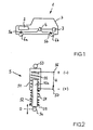
- Fig.1 shows a motor vehicle 1.
- a drive motor 2 which may be designed as an internal combustion engine or as an electric motor. Instead of the drive motor 2, a hybrid drive can also be provided.
- the motor vehicle 2 further comprises a motor vehicle battery 3, which stores and emits electrical energy, for example for starting or operating the drive motor 2. Instead of a single motor vehicle battery 3, a multiplicity of motor vehicle batteries may also be included.
- the motor vehicle battery 3 is preferably designed as a lithium-ion battery.
- a control unit 4 is included, which regulates the charging of the motor vehicle battery and its discharge, ie the power output.
- the wheels 6a and 6b are connected via shock absorbers 5a and 5b of a vehicle suspension with the body 7 of the motor vehicle.
- the charging current for charging the motor vehicle battery 3 is at least partially obtained by converting a mechanical power to the vehicle suspension according to the invention.
- the shock absorber 5a and 5b with a Transducer equipped which at least partially converts the mechanical spring power or spring energy into electrical power or electrical energy, which is used as charging current for charging the motor vehicle battery 3.
- the charging current and thus the charging of the vehicle battery 3 is regulated by the control unit 4.
- Fig. 2 shows the structure of a shock absorber 5 in a schematic sectional view.
- This includes a strut 52 which is telescopically mounted in a receptacle 51.
- a helical spring 58 is arranged, which is supported against a spring plate 59 and against the receptacle 51.
- the spring 58 is intended to absorb road shocks and convert them into vibrations, as well as to ensure the roadway contact of the connected wheel 6a and 6b.
- the shock absorber 5 fastening means 53 and 54 which are exemplified here as eyelets.
- the strut 52 has with respect to the receptacle 51 on a constructively fixed zero position 0, which can be indicated, for example, by the position of the lower fastening device 54.
- the zero position of a wheel 6a or 6b to the structure 7 is defined.
- the strut 52 can take a positive spring travel, i. as shown up in the receptacle 51 spring, and take a negative spring travel, i. as shown, rebound downwards.
- the end 52a of the strut 52 has a permanent magnet device, whereby an electrical voltage U is induced in the coil 55 according to the laws of physical induction, which can be tapped between the contacts 56 and 57.
- the sign of the electrical voltage U is dependent on the instantaneous direction of movement of the strut 52 relative to the receptacle 51. In this way, taking into account an efficiency, a mechanical spring power can be converted into an electrical power, which is used as charging current for the vehicle battery 3.
- shock absorber 5 The tapped between the terminals 56 and 57 electrical power simultaneously affects the damping behavior of the shock absorber 5, so that on the electric power extraction and the spring behavior of the vehicle suspension can be changed or adjusted and thus adjusted situation required. This is likewise regulated via the control device 4.
- the shock absorber 5 may be provided with further damping elements, such as e.g. an oil pressure or gas pressure damper.
- a controllable electromagnet can also be used. Notwithstanding the embodiment of a shock absorber 5 shown, the coil 55 can also be arranged on the receptacle 51 at the end 52a of the strut 52 and a permanent magnet device and / or electromagnet device.
- a linear motor can be integrated into the shock absorber 5, which can be operated either as a generator or as a servomotor.
- the damping behavior of the shock absorber can be actively changed, which is regulated by the situation required by the control unit 4.
- shock absorber 5 instead of the telescopic shock absorber 5 shown with the coil spring 58, other shock absorber types can be used, which include, for example, a leaf spring or a torsion bar spring.
- the converter for converting the mechanical spring power into electrical power is then appropriate to adapt to the respective shock absorber type.
- rotatable transducers instead of the longitudinally movable transducer described above, also rotatable transducers can be used.
Landscapes
- Engineering & Computer Science (AREA)
- Mechanical Engineering (AREA)
- Transportation (AREA)
- Chemical & Material Sciences (AREA)
- Combustion & Propulsion (AREA)
- Automation & Control Theory (AREA)
- Power Engineering (AREA)
- Electric Propulsion And Braking For Vehicles (AREA)
- Vehicle Body Suspensions (AREA)
- Charge And Discharge Circuits For Batteries Or The Like (AREA)
- Secondary Cells (AREA)
- Vibration Prevention Devices (AREA)
Description
- Die Erfindung betrifft ein Verfahren zum Aufladen einer Kraftfahrzeugbatterie während des Betriebs des Kraftfahrzeugs, sowie eine Ladevorrichtung und ein Kraftfahrzeug umfassend eine solche Ladevorrichtung.
- Der Betrieb eines Kraftfahrzeugs ist auf vielerlei Arten stets verlustbehaftet. Hierunter ist zu verstehen, dass eine für den Betrieb des Kraftfahrzeugs potentiell zur Verfügung stehende Energie, wie z.B. die elektrische Energie einer Batterie oder die latente Energie eines Kraftstoffs, nur bedingt für den Betrieb des Kraftfahrzeugs genutzt werden kann. Aus dem Stand der Technik sind zahlreiche Ansätze bekannt, um die Energieeffizienz beim Betrieb eines Kraftfahrzeugs zu verbessern, indem z.B. Maßnahmen zur Erhöhung des Wirkungsgrads bei der Energiewandlung ergriffen werden.
- Die
WO 2007/106057 A2 beschreibt ein System und ein Verfahren zur Erzeugung elektrischer Energie aus mechanischer Deformationsenergie einer Fahrzeug-Radaufhängung. - Die Aufgabe der Erfindung ist es, die Energieeffizienz beim Betrieb eines Kraftfahrzeugs weiterhin zu verbessern. Diese Aufgabe wird gelöst von einem Verfahren oder einer Vorrichtung gemäß einem der unabhängigen Patentansprüche. Vorteilhafte und bevorzugte Weiterbildungen sind Gegenstand der jeweils abhängigen Ansprüche.
- Erfindungsgemäß wird ein Verfahren zum Aufladen bzw. elektrischen Beladen wenigstens einer Kraftfahrzeugbatterie während des Betriebs des Kraftfahrzeugs vorgeschlagen, bei dem der Ladestrom für die Kraftfahrzeugbatterie zumindest teilweise durch das Umwandeln einer mechanischen Leistung an der Fahrzeugfederung gewonnen wird.
- Eine Kraftfahrzeugbatterie ist eine Komponente, die elektrische Energie speichert und diese, bspw. zum Starten eines Verbrennungsmotors und/oder zum Betrieb eines Elektromotors, wieder abgibt. Gemäß ihrer Funktion kann eine solche Batterie auch als Akkumulator bezeichnet werden. Kraftfahrzeugbatterien sind für verschiedene Anwendungszwecke und in unterschiedlichen Spezifikationen am Markt insbesondere als fertig hergerichtete Komponenten erhältlich. Erfindungsgemäß kann auch eine Vielzahl von Kraftfahrzeugbatterien vorgesehen sein, die gleichzeitig oder nach einer festgelegten Hierarchie elektrisch aufgeladen werden.
- Die Fahrzeugfederung ist Teil des Fahrwerks eines Kraftfahrzeugs. Sie soll gewährleisten, dass die Räder des Kraftfahrzeugs etwaigen Fahrbahnunebenheiten folgen, während hingegen der Aufbau des Kraftfahrzeugs hiervon weitgehend unbeeinflusst bleibt. Die Fahrzeugfederung dient damit einerseits dem Fahrkomfort, andererseits aber auch der Fahrsicherheit, indem sie den Fahrbahnkontakt der Räder gewährleistet. Eine Fahrzeugfederung umfasst meist mehrere Feder-Dämpfer-Kombination, die auch als Stoßdämpfer bezeichnet werden, und welche die Räder des Kraftfahrzeugs vom Aufbau des Kraftfahrzeugs schwingungsmäßig entkoppeln.
- Moderne Berechungsverfahren zeigen, dass die Verlustleistung an der Fahrzeugfederung für einen Mittelklasse-PKW, der mit 100 km/h auf einer im wesentlichen ebenen Betonfahrbahn fährt, insgesamt etwa 4 kW und mehr beträgt. Die Erfindung beruht auf der Idee, diese Verlustleistung durch das Umwandeln in eine elektrische Energie bzw. in eine elektrische Leistung zurückzugewinnen und für das Aufladen der Kraftfahrzeugbatterie zu nutzen. Dies wird durch das erfindungsgemäße Verfahren bewerkstelligt. Dadurch kann die Energieeffizienz beim Betrieb eines Kraftfahrzeugs verbessert werden, wodurch der Energieverbrauch des Kraftfahrzeugs und die damit einhergehende Umweltbelastung gesenkt wird. Die Erfindung eignet sich gleichermaßen für PKWs und LKWs. Zudem eignet sich die Erfindung auch zur Nachrüstung älterer Kraftfahrzeuge.
- Gemäß einer bevorzugten Weiterbildung ist vorgesehen, dass die mechanische Leistung an der Fahrzeugfederung eine Federleistung an wenigstens einem Stoßdämpfer des Kraftfahrzeugs ist, die zumindest teilweise in eine elektrische Leistung umgewandelt und als Ladestrom für die Kraftfahrzeugbatterie genutzt wird.
- Wie oben bereits erläutert ist ein Stoßdämpfer eine Feder-Dämpfer-Kombination. Die Feder soll Fahrbahnstöße auffangen und in Schwingungen umwandeln. Der Dämpfer soll diese Schwingungen in möglichst kurzer Zeit dämpfen. Gemäß dem Stand der Technik wird hierbei ein Teil der Federleistung (Produkt aus Kraft und Federweg) in Wärme umgewandelt, welche ungenutzt an die Umgebung abgegeben wird. Demgegenüber wird erfindungsgemäß vorgeschlagen, aus dieser Federleistung zumindest teilweise einen Ladestrom zu generieren und diesen zum Aufladen der Kraftfahrzeugbatterie zu nutzen. Demnach fungiert der Stoßdämpfer als Generator. Das Abgreifen der generierten elektrischen Leistung am Stoßdämpfer erhöht zudem dessen Dämpfungswirkung. Durch schaltungstechnische und/oder steuerungstechnische Maßnahmen kann ferner auch eine asymptotische Dämpfung des Stoßdämpfers begünstigt werden.
- Gemäß einer bevorzugten Weiterbildung ist vorgesehen, dass das Umwandeln an einem Stoßdämpfer auf einem induktiven Prinzip und/oder auf einem Piezo-Prinzip basiert. Das induktive Prinzip lässt sich insbesondere durch eine Spulen-Magnet-Kombination umsetzen, bei der durch Relativbewegung von Spule und Magnet eine nutzbare elektrische Spannung induziert wird. Das Piezo-Prinzip lässt sich bspw. durch Verwendung von handelsüblichen Piezokomponenten umsetzen. Alternativ und/oder ergänzend ist auch ein elektrochemisches Wandlungsprinzip denkbar.
- Gemäß einer bevorzugten Weiterbildung ist vorgesehen, dass das Umwandeln zumindest eines Teils der mechanischen Federleistung in eine elektrische Leistung sowohl bei einem positiven Federweg als auch bei einem negativen Federweg am Stoßdämpfer erfolgt. Ein positiver Federweg ist beim Einfedern eines Rads in Richtung des Aufbaus des Kraftfahrzeugs gegeben, ein negativer Federweg ist beim entgegengesetzten Ausfedern eines Rads gegeben. Insbesondere ist vorgesehen, dass das Umwandeln zumindest beim Einfedern erfolgt.
- Erfindungsgemäß wird ferner eine Ladevorrichtung für wenigstens eine Kraftfahrzeugbatterie vorgeschlagen, wobei diese Ladevorrichtung wenigstens einen Wandler umfasst, der eine mechanische Leistung an der Fahrzeugfederung zumindest teilweise in eine elektrische Leistung umwandelt und diese als Ladestrom für die Kraftfahrzeugbatterie bereitstellt. Diese Ladevorrichtung ist insbesondere für den Betrieb mit dem erfindungsgemäßen Verfahren geeignet bzw. hergerichtet. An dieser Stelle wird auf die obigen Ausführungen zum erfindungsgemäßen Verfahren verwiesen, welche sinngemäß auch auf die erfindungsgemäße Ladevorrichtung zutreffen.
- Gemäß einer bevorzugten Weiterbildung ist vorgesehen, dass der Wandler in einen Stoßdämpfer der Fahrzeugfederung integriert ist. Der Begriff "integriert" ist hierbei weit auszulegen und umfasst jegliche kraftgekoppelte Anordnung von Stoßdämpfer und Wandler.
- Gemäß einer bevorzugten Weiterbildung ist vorgesehen, dass der Wandler aus einer Spulen-Magnet-Kombination gebildet ist. Ein Magnet ist insbesondere ein Permanentmagnet. Ein Magnet kann hingegen auch ein Elektromagnet sein. Dies wird nachfolgend im Zusammenhang mit den Figuren noch näher erläutert.
- Gemäß einer bevorzugten Weiterbildung ist vorgesehen, dass ein Stoßdämpfer wenigstens einen Linearmotor umfasst, der als Generator betrieben werden kann. Ein Linearmotor im Sinne der Erfindung ist ein elektromechanischer Wandler, der eine elektrische Größe, wie insbesondere einen Strom, in eine mechanische geradlinige Bewegung (Translationsbewegung) umsetzen kann und/oder umgekehrt. Bevorzugt kann dieser Linearmotor auch als Stellmotor betrieben werden, wodurch das Dämpfungsverhalten des Stoßdämpfers und damit das Federverhalten der Fahrzeugfederung bspw. situationserforderlich angepasst werden kann.
- Gemäß einer bevorzugten Weiterbildung ist vorgesehen, dass eine Steuereinheit zur Regelung des Ladestroms umfasst ist. Die Steuereinheit ermöglicht u.a. eine Gleichrichtung, eine Linearisierung und/oder eine Begrenzung des Ladestroms, sowie eine Überwachung des Ladevorgangs einer Kraftfahrzeugbatterie in Echtzeit. Die Steuereinheit ermöglicht bevorzugt auch eine Regelung des Dämpfungsverhaltens wenigstens eines Stoßdämpfers. Insbesondere umfasst der Stoßdämpfer hierzu einen als Stellmotor betreibbaren Linearmotor, wie zuvor erläutert, der von der Steuereinheit angesteuert wird.
- Gemäß einer bevorzugten Weiterbildung ist vorgesehen, dass die aufzuladende Kraftfahrzeugbatterie eine Lithium-Ionen-Batterie ist. Die Kombination mit einer solchen Lithium-Ionen-Batterie hat sich als besonders vorteilhaft erwiesen, da eine solche dynamische Auflade- und Entladevorgänge ermöglicht.
- Erfindungsgemäß wird ferner ein Kraftfahrzeug vorgeschlagen, umfassend eine erfindungsgemäße Ladevorrichtung.
- Gemäß einer bevorzugten Weiterbildung ist vorgesehen, dass dieses Kraftfahrzeug einen Elektroantrieb oder einen Hybridantrieb umfasst, der zumindest teilweise von der aufzuladenden Kraftfahrzeugbatterie mit Energie versorgt wird.
- Weitere Vorteile, Merkmale und Anwendungsmöglichkeiten der vorliegenden Erfindung ergeben sich aus der nachfolgenden beispielhaften Beschreibung in Zusammenhang mit den Figuren. Es zeigen:
- Fig. 1
- ein erfindungsgemäßes Kraftfahrzeug in einer schematischen Ansicht, und
- Fig. 2
- eine schematische Schnittansicht eines Stoßdämpfers des Kraftfahrzeugs der
Fig. 1 . -
Fig.1 zeigt ein Kraftfahrzeug 1. Dieses umfasst einen Antriebsmotor 2, der als Verbrennungsmotor oder als Elektromotor ausgeführt sein kann. Anstelle des Antriebsmotors 2 kann auch ein Hybridantrieb vorgesehen sein. Das Kraftfahrzeug 2 umfasst weiterhin eine Kraftfahrzeugbatterie 3, die elektrische Energie speichert und diese wieder abgibt, bspw. zum Starten oder zum Betrieb des Antriebsmotors 2. Anstelle einer einzelnen Kraftfahrzeugbatterie 3 kann auch eine Vielzahl an Kraftfahrzeugbatterien umfasst sein. Die Kraftfahrzeugbatterie 3 ist bevorzugt als Lithium-Ionen-Batterie ausgeführt. Ferner ist eine Steuereinheit 4 umfasst, welche die Aufladung der Kraftfahrzeugbatterie und deren Entladung, d.h. die Leistungsabgabe, regelt. Die Räder 6a und 6b sind über Stoßdämpfer 5a und 5b einer Fahrzeugfederung mit dem Aufbau 7 des Kraftfahrzeugs verbunden. - Der Ladestrom zur Aufladung der Kraftfahrzeugbatterie 3 wird erfindungsgemäß zumindest teilweise durch das Umwandeln einer mechanischen Leistung an der Fahrzeugfederung gewonnen. Hierzu sind die Stoßdämpfer 5a und 5b mit einem Wandler ausgerüstet, der die mechanische Federleistung bzw. Federenergie zumindest teilweise in eine elektrische Leistung bzw. elektrische Energie umwandelt, die als Ladestrom zum Aufladen der Kraftfahrzeugbatterie 3 verwendet wird. Der Ladestrom und damit die Aufladung der Fahrzeugbatterie 3 wird von der Steuereinheit 4 geregelt.
-
Fig. 2 zeigt den Aufbau eines Stoßdämpfers 5 in einer schematischen Schnittansicht. Dieser umfasst ein Federbein 52 das teleskopartig in einer Aufnahme 51 gelagert ist. Koaxial zum Federbein 52 ist eine Schraubenfeder 58 angeordnet, welche sich gegen einen Federteller 59 und gegen die Aufnahme 51 abstützt. Die Feder 58 soll Fahrbahnstöße auffangen und in Schwingungen umwandeln, sowie den Fahrbahnkontakt des angebundenen Rads 6a bzw. 6b gewährleisten. Zur Verbindung mit dem Rad 6a bzw. 6b und mit dem Aufbau 7 weist der Stoßdämpfer 5 Befestigungseinrichtungen 53 und 54 auf, die hier beispielhaft als Ösen ausgebildet sind. - Das Federbein 52 weist bezüglich der Aufnahme 51 eine konstruktiv festgelegte Null-Lage 0 auf, die bspw. durch die Position der unteren Befestigungsvorrichtung 54 angegeben werden kann. Hierdurch ist auch die Null-Lage eines Rads 6a bzw. 6b zum Aufbau 7 definiert. Ausgehend von dieser Nulllage 0 kann das Federbein 52 einen positiven Federweg beschreiten, d.h. gemäß der Darstellung nach oben in die Aufnahme 51 einfedern, und einen negativen Federweg beschreiten, d.h. gemäß der Darstellung nach unten ausfedern.
- Bei einer Bewegung des Federbeins 52 bewegt sich dessen in der Aufnahme 51 befindliches Ende 52a innerhalb einer in der Aufnahme 51 angeordneten elektrischen Spule 55. Die Spule 55 ist hier als einlagige Wicklung dargestellt, kann jedoch auch mehrlagig ausgebildet sein. Das Ende 52a des Federbeins 52 weist eine Permanentmagneteinrichtung auf, wodurch in der Spule 55 nach den physikalischen Induktionsgesetzen eine elektrische Spannung U induziert wird, die zwischen den Kontakten 56 und 57 abgreifbar ist. Das Vorzeichen der elektrischen Spannung U ist abhängig von der momentanen Bewegungsrichtung des Federbeins 52 relativ zur Aufnahme 51. Auf diese Weise kann unter Berücksichtigung eines Wirkungsgrads eine mechanische Federleistung in eine elektrische Leistung umgewandelt werden, die als Ladestrom für die Fahrzeugbatterie 3 genutzt wird.
- Die zwischen den Anschlüssen 56 und 57 abgegriffene elektrische Leistung beeinflusst gleichzeitig das Dämpfungsverhalten des Stoßdämpfers 5, so dass über die elektrische Leistungsentnahme auch das Federverhalten der Fahrzeugfederung verändert bzw. eingestellt und damit situationserforderlich angepasst werden kann. Dies wird gleichfalls über die Steuereinrichtung 4 geregelt. Ergänzend kann der Stoßdämpfer 5 mit weiteren Dämpfungselementen versehen sein, wie z.B. einem Öldruck- oder Gasdruckdämpfer.
- Anstelle einer Permanentmagneteinrichtung am Ende 52a des Federbeins 52 kann auch ein regelbarer Elektromagnet eingesetzt werden. Abweichend von der gezeigten Ausführungsform eines Stoßdämpfers 5 kann die Spule 55 auch am Ende 52a des Federbeins 52 und eine Permanentmagneteinrichtung und/oder Elektromagneteinrichtung an der Aufnahme 51 angeordnet werden.
- Anstelle der gezeigten Spulen-Magnet-Kombination kann auch ein Linearmotor in den Stoßdämpfer 5 integriert werden, der wahlweise als Generator oder als Stellmotor betrieben werden kann. Hierdurch kann das Dämpfungsverhalten des Stoßdämpfers aktiv verändert werden, was situationserforderlich durch die Steuereinheit 4 geregelt wird.
- Anstelle des gezeigten teleskopartigen Stoßdämpfers 5 mit der Schraubenfeder 58 können auch andere Stoßdämpfertypen eingesetzt werden, die z.B. eine Blattfeder oder eine Drehstabfeder umfassen. Der Wandler zum Umwandeln der mechanischen Federleistung in eine elektrische Leistung ist dann entsprechend an den jeweiligen Stoßdämpfertyp anzupassen. So können z.B. anstelle des oben beschriebenen längsbeweglichen Wandlers auch drehbewegliche Wandler eingesetzt werden.
Claims (7)
- Verfahren zum Aufladen wenigstens einer Kraftfahrzeugbatterie (3) während des Betriebs des Kraftfahrzeugs (1), bei dem der Ladestrom für die Kraftfahrzeugbatterie (3) zumindest teilweise durch das Umwandeln einer mechanischen Leistung der Fahrzeugfederung gewonnen wird und die mechanische Leistung eine Federleistung an wenigstens einem Stoßdämpfer (5) des Kraftfahrzeugs (1) ist,
dadurch gekennzeichnet,
dass eine Steuereinheit (4) zur Regelung des Ladestroms eine Regelung des Dämpfungsverhaltens wenigstens eines Stoßdämpfers (5) ermöglicht, und dass der Stoßdämpfer (5) wenigstens einen Linearmotor umfasst, der als Generator und als Stellmotor betrieben wird. - Verfahren nach Anspruch 1,
dadurch gekennzeichnet,
dass das Umwandeln auf einem induktiven Prinzip oder auf einem Piezo-Prinzip basiert. - Verfahren nach Anspruch 2,
dadurch gekennzeichnet,
dass das Umwandeln sowohl bei einem positiven Federweg als auch bei einem negativen Federweg erfolgt. - Ladevorrichtung für wenigstens eine Kraftfahrzeugbatterie (3), welche insbesondere für den Betrieb mit einem Verfahren gemäß einem der vorausgehenden Ansprüche geeignet ist, die wenigstens einen Wandler umfasst, der eine mechanische Leistung an der Fahrzeugfederung zumindest teilweise in eine elektrische Leistung umwandelt und diese als Ladestrom für die Kraftfahrzeugbatterie (3) bereitstellt, wobei der Wandler in einem Stoßdämpfer (5) der Fahrzeugfederung integriert ist,
dadurch gekennzeichnet,
dass sie eine Steuereinheit (4) zur Regelung des Ladestroms umfasst, die eine Regelung des Dämpfungsverhaltens wenigstens eines Stoßdämpfers (5) ermöglicht, und dass der Stoßdämpfer (5) wenigstens einen Linearmotor umfasst, der als Generator und als Stellmotor betreibbar ist. - Ladevorrichtung nach Anspruch 4,
dadurch gekennzeichnet,
dass die aufzuladende Kraftfahrzeugbatterie (3) eine Lithium-lonen-Batterie ist. - Kraftfahrzeug (1) umfassend eine Ladevorrichtung gemäß einem der Ansprüche 4 bis 5.
- Kraftfahrzeug (1) nach Anspruch 6,
dadurch gekennzeichnet,
dass dieses einen Elektroantrieb oder einen Hybridantrieb umfasst, der zumindest teilweise von der aufzuladenden Kraftfahrzeugbatterie (3) mit Energie versorgt wird.
Applications Claiming Priority (2)
| Application Number | Priority Date | Filing Date | Title |
|---|---|---|---|
| DE102009010144A DE102009010144A1 (de) | 2009-02-23 | 2009-02-23 | Verfahren und Ladevorrichtung zum Aufladen einer Kraftfahrzeugbatterie |
| PCT/EP2009/008686 WO2010094312A1 (de) | 2009-02-23 | 2009-12-04 | Verfahren und ladevorrichtung zum aufladen einer kraftfahrzeugbatterie |
Publications (2)
| Publication Number | Publication Date |
|---|---|
| EP2398660A1 EP2398660A1 (de) | 2011-12-28 |
| EP2398660B1 true EP2398660B1 (de) | 2014-03-12 |
Family
ID=41566352
Family Applications (1)
| Application Number | Title | Priority Date | Filing Date |
|---|---|---|---|
| EP09765041.0A Not-in-force EP2398660B1 (de) | 2009-02-23 | 2009-12-04 | Verfahren und ladevorrichtung zum aufladen einer kraftfahrzeugbatterie |
Country Status (8)
| Country | Link |
|---|---|
| US (1) | US20120133334A1 (de) |
| EP (1) | EP2398660B1 (de) |
| JP (1) | JP2012518976A (de) |
| KR (1) | KR20120009433A (de) |
| CN (1) | CN102361763A (de) |
| BR (1) | BRPI0924277A2 (de) |
| DE (1) | DE102009010144A1 (de) |
| WO (1) | WO2010094312A1 (de) |
Families Citing this family (18)
| Publication number | Priority date | Publication date | Assignee | Title |
|---|---|---|---|---|
| DE102011010165B4 (de) * | 2011-02-02 | 2018-11-22 | Patrick Becker | Magnetische Feder |
| DE102011052923B4 (de) * | 2011-08-23 | 2016-11-24 | Gsi Helmholtzzentrum Für Schwerionenforschung Gmbh | Energieübertragungseinheit |
| DE102012212474A1 (de) * | 2012-07-17 | 2014-01-23 | Bayerische Motoren Werke Aktiengesellschaft | Schwingungsdämpfer mit einem Piezoelement sowie Verfahren zur Ansteuerung eines solchen Schwingungsdämpfers |
| CN103448547B (zh) * | 2013-09-17 | 2016-04-13 | 东风汽车公司 | 一种悬架运动能量回收机构 |
| AT515231B1 (de) * | 2014-01-09 | 2015-09-15 | Trumpf Maschinen Austria Gmbh | Unterwerkzeug einer Biegepresse mit einer Biegewinkelmessvorrichtung |
| DE102015203120B4 (de) * | 2015-02-20 | 2020-12-10 | Ford Global Technologies, Llc | Dynamische Anpassung von Spur und Sturz mittels einer piezoelektrischen Einrichtung |
| DK3176942T3 (en) | 2015-12-02 | 2018-05-07 | Andres Cuenca Francisco Jose | PIEZOELECTRIC GENERATOR SYSTEM AND ELECTRICAL SYSTEM INCLUDING SUCH A PIEZOELECTRIC GENERATOR SYSTEM |
| ITUB20159167A1 (it) * | 2015-12-17 | 2017-06-17 | Davide Carini | Sospensione ottimizzata di veicoli, e relativo kit |
| DE102017210707A1 (de) * | 2017-06-26 | 2018-12-27 | Volkswagen Aktiengesellschaft | Antriebssystem |
| US11161421B2 (en) | 2017-08-29 | 2021-11-02 | Toyota Motor Engineering & Manufacturing North America, Inc. | Auxiliary wireless power transfer system |
| DE102018202854B4 (de) | 2018-02-26 | 2020-01-02 | Audi Ag | Verfahren zum Betrieb eines Bordnetzes eines Hybridkraftfahrzeugs und Hybridkraftfahrzeug |
| US10828955B1 (en) | 2018-06-29 | 2020-11-10 | Zoox, Inc. | Vehicle suspension system with remote actuation |
| WO2020117467A1 (en) | 2018-12-07 | 2020-06-11 | Carrier Corporation | Generators for transport refrigeration systems |
| CN111409284B (zh) * | 2020-03-09 | 2021-07-27 | 华中科技大学 | 一种基于4d打印的柔性压电传感器及其制备方法 |
| US12011960B2 (en) | 2021-02-17 | 2024-06-18 | Francis Walls | Kinetic energy shock absorber |
| KR102532403B1 (ko) | 2021-03-30 | 2023-05-15 | 제주대학교 산학협력단 | 차량용 배터리의 무선 충전 장치 및 방법 |
| AT525071B1 (de) * | 2021-06-29 | 2022-12-15 | Pagitz Andreas | Federweggenerator |
| DE102025148335A1 (de) | 2024-12-06 | 2026-06-11 | Daimler Truck AG | Auspuffflexrohreinrichtung eines fahrzeugs und fahrzeug, das dieselbe beinhaltet |
Family Cites Families (13)
| Publication number | Priority date | Publication date | Assignee | Title |
|---|---|---|---|---|
| BE881528A (fr) * | 1980-02-04 | 1980-05-30 | Staar Dev Cy S A | Systeme de recuperation d'energie |
| FR2619765B1 (fr) * | 1987-08-25 | 1994-02-11 | Patinier Andre | Dispositif piezo-electrique de recuperation d'energie dans des suspensions du type a ressorts a lames |
| CA1336616C (en) * | 1988-10-05 | 1995-08-08 | I. Davis Roy | Electrically powered active suspension for a vehicle |
| IT1289322B1 (it) * | 1996-01-19 | 1998-10-02 | Carlo Alberto Zenobi | Dispositivo per l'ottenimento di energia elettrica dalle azioni dinamiche derivanti dal moto relativo tra veicoli e suolo |
| US6952060B2 (en) * | 2001-05-07 | 2005-10-04 | Trustees Of Tufts College | Electromagnetic linear generator and shock absorber |
| JP2005162082A (ja) * | 2003-12-04 | 2005-06-23 | Honda Motor Co Ltd | 車両用サスペンション装置 |
| EP1704632A1 (de) * | 2003-12-12 | 2006-09-27 | Gerald Beaulieu | Linear-generator-vorrichtung |
| CN1292930C (zh) * | 2004-11-08 | 2007-01-03 | 西安交通大学 | 汽车振动能量压电发电方法及其系统 |
| JP2007203933A (ja) * | 2006-02-03 | 2007-08-16 | Toyota Motor Corp | サスペンション装置 |
| WO2007106057A2 (en) * | 2006-02-15 | 2007-09-20 | Michelin Recherche Et Technique S.A. | System and method for generating electric power from mechanical strains within a vehicle suspension system |
| US7887033B2 (en) * | 2006-06-06 | 2011-02-15 | Deere & Company | Suspension system having active compensation for vibration |
| JP2008286362A (ja) * | 2007-05-21 | 2008-11-27 | Aisin Seiki Co Ltd | サスペンション装置 |
| JP4692521B2 (ja) * | 2007-06-29 | 2011-06-01 | アイシン・エィ・ダブリュ株式会社 | 車両制御装置、車両制御方法及びコンピュータプログラム |
-
2009
- 2009-02-23 DE DE102009010144A patent/DE102009010144A1/de not_active Withdrawn
- 2009-12-04 EP EP09765041.0A patent/EP2398660B1/de not_active Not-in-force
- 2009-12-04 WO PCT/EP2009/008686 patent/WO2010094312A1/de not_active Ceased
- 2009-12-04 BR BRPI0924277A patent/BRPI0924277A2/pt not_active IP Right Cessation
- 2009-12-04 CN CN2009801574000A patent/CN102361763A/zh active Pending
- 2009-12-04 JP JP2011550423A patent/JP2012518976A/ja active Pending
- 2009-12-04 US US13/202,841 patent/US20120133334A1/en not_active Abandoned
- 2009-12-04 KR KR1020117022216A patent/KR20120009433A/ko not_active Withdrawn
Also Published As
| Publication number | Publication date |
|---|---|
| WO2010094312A8 (de) | 2011-10-06 |
| US20120133334A1 (en) | 2012-05-31 |
| KR20120009433A (ko) | 2012-01-31 |
| CN102361763A (zh) | 2012-02-22 |
| BRPI0924277A2 (pt) | 2016-01-26 |
| EP2398660A1 (de) | 2011-12-28 |
| DE102009010144A1 (de) | 2010-08-26 |
| WO2010094312A1 (de) | 2010-08-26 |
| JP2012518976A (ja) | 2012-08-16 |
Similar Documents
| Publication | Publication Date | Title |
|---|---|---|
| EP2398660A1 (de) | Verfahren und ladevorrichtung zum aufladen einer kraftfahrzeugbatterie | |
| DE102009035482B4 (de) | Batterie mit einer Vielzahl von Batterieeinzelzellen | |
| EP2640588B1 (de) | Elektrisch angetriebene achse eines zweispurigen fahrzeugs | |
| EP2595822A1 (de) | Energierekuperation aus einer fahrzeugfederung | |
| DE102010016188A1 (de) | Verfahren zum Betreiben eines Elektrofahrzeuges | |
| DE102015004701A1 (de) | Elektrofahrzeug mit Schnellladefunktion | |
| DE102018200329A1 (de) | Fahrgestellvorrichtung eines elektrisch antreibbaren Kraftfahrzeugs | |
| DE102019111980A1 (de) | Energieversorgungseinheit für aktives fahrwerksystem | |
| DE102017103397A1 (de) | Achsantriebseinheit, Antriebsachse und Kraftfahrzeug | |
| DE102010036658A1 (de) | Vorrichtung | |
| WO2006128599A1 (de) | Energiespeichereinrichtung | |
| DE102013200013A1 (de) | Fahrwerkvorrichtung | |
| DE102019004099A1 (de) | Mit Auflaufbremse ausgestatteter Anhänger mit Bremsenergie-Rückgewinnung | |
| DE10220846A1 (de) | Fahrzeug, insbesondere motorgetriebenes Strassenfahrzeug | |
| DE102012001890A1 (de) | Energiespeichersystem für ein elektrisch antreibbares Fahrzeug | |
| DE102017212545A1 (de) | Aufhängungssystem | |
| DE102012208285B3 (de) | Energierückgewinnungssystem im Fahrzeug | |
| DE102019213773A1 (de) | Verfahren zum Steuern einer Bremswirkung an einem Fahrzeug mit einem elektrischen Antriebssystem und System für eine Bremsunterstützung bei einem Fahrzeug mit einem elektrischen Antriebssystem | |
| EP1470018B2 (de) | Fahrzeug mit bremsenergiespeicher | |
| DE102016015255A1 (de) | Ladevorrichtung und Verfahren zu deren Betrieb | |
| DE102024200939A1 (de) | Lastkraftwagen mit Energieerzeugungseinrichtung | |
| EP3509884A1 (de) | Hybridfahrzeug mit induktiver lademöglichkeit | |
| DE202012004613U1 (de) | Nutzfahrzeug | |
| DE102020119127A1 (de) | Verfahren zum Betreiben eines Kraftfahrzeugs sowie entsprechendes Kraftfahrzeug | |
| EP3150424B1 (de) | Verfahren und vorrichtung zum energiemanagement in einem kraftfahrzeug mit mindestens zwei angetriebenen fahrzeugachsen |
Legal Events
| Date | Code | Title | Description |
|---|---|---|---|
| PUAI | Public reference made under article 153(3) epc to a published international application that has entered the european phase |
Free format text: ORIGINAL CODE: 0009012 |
|
| 17P | Request for examination filed |
Effective date: 20110922 |
|
| AK | Designated contracting states |
Kind code of ref document: A1 Designated state(s): AT BE BG CH CY CZ DE DK EE ES FI FR GB GR HR HU IE IS IT LI LT LU LV MC MK MT NL NO PL PT RO SE SI SK SM TR |
|
| DAX | Request for extension of the european patent (deleted) | ||
| RIN1 | Information on inventor provided before grant (corrected) |
Inventor name: LACHENMEIER, WALTER Inventor name: SCHAEFER, TIM Inventor name: GUTSCH, ANDREAS |
|
| 17Q | First examination report despatched |
Effective date: 20121203 |
|
| REG | Reference to a national code |
Ref country code: DE Ref legal event code: R079 Ref document number: 502009008992 Country of ref document: DE Free format text: PREVIOUS MAIN CLASS: B60G0017015000 Ipc: B60W0010260000 |
|
| RIC1 | Information provided on ipc code assigned before grant |
Ipc: B60W 10/26 20060101AFI20130627BHEP Ipc: B60G 17/015 20060101ALI20130627BHEP Ipc: H02N 2/18 20060101ALI20130627BHEP Ipc: B60W 20/00 20060101ALI20130627BHEP |
|
| GRAP | Despatch of communication of intention to grant a patent |
Free format text: ORIGINAL CODE: EPIDOSNIGR1 |
|
| INTG | Intention to grant announced |
Effective date: 20130927 |
|
| GRAS | Grant fee paid |
Free format text: ORIGINAL CODE: EPIDOSNIGR3 |
|
| GRAA | (expected) grant |
Free format text: ORIGINAL CODE: 0009210 |
|
| AK | Designated contracting states |
Kind code of ref document: B1 Designated state(s): AT BE BG CH CY CZ DE DK EE ES FI FR GB GR HR HU IE IS IT LI LT LU LV MC MK MT NL NO PL PT RO SE SI SK SM TR |
|
| REG | Reference to a national code |
Ref country code: GB Ref legal event code: FG4D Free format text: NOT ENGLISH |
|
| REG | Reference to a national code |
Ref country code: CH Ref legal event code: EP |
|
| REG | Reference to a national code |
Ref country code: AT Ref legal event code: REF Ref document number: 656066 Country of ref document: AT Kind code of ref document: T Effective date: 20140315 |
|
| REG | Reference to a national code |
Ref country code: IE Ref legal event code: FG4D Free format text: LANGUAGE OF EP DOCUMENT: GERMAN |
|
| REG | Reference to a national code |
Ref country code: DE Ref legal event code: R096 Ref document number: 502009008992 Country of ref document: DE Effective date: 20140417 |
|
| REG | Reference to a national code |
Ref country code: NL Ref legal event code: VDEP Effective date: 20140312 |
|
| PG25 | Lapsed in a contracting state [announced via postgrant information from national office to epo] |
Ref country code: NO Free format text: LAPSE BECAUSE OF FAILURE TO SUBMIT A TRANSLATION OF THE DESCRIPTION OR TO PAY THE FEE WITHIN THE PRESCRIBED TIME-LIMIT Effective date: 20140612 Ref country code: LT Free format text: LAPSE BECAUSE OF FAILURE TO SUBMIT A TRANSLATION OF THE DESCRIPTION OR TO PAY THE FEE WITHIN THE PRESCRIBED TIME-LIMIT Effective date: 20140312 |
|
| REG | Reference to a national code |
Ref country code: LT Ref legal event code: MG4D |
|
| PG25 | Lapsed in a contracting state [announced via postgrant information from national office to epo] |
Ref country code: FI Free format text: LAPSE BECAUSE OF FAILURE TO SUBMIT A TRANSLATION OF THE DESCRIPTION OR TO PAY THE FEE WITHIN THE PRESCRIBED TIME-LIMIT Effective date: 20140312 Ref country code: SE Free format text: LAPSE BECAUSE OF FAILURE TO SUBMIT A TRANSLATION OF THE DESCRIPTION OR TO PAY THE FEE WITHIN THE PRESCRIBED TIME-LIMIT Effective date: 20140312 Ref country code: CY Free format text: LAPSE BECAUSE OF FAILURE TO SUBMIT A TRANSLATION OF THE DESCRIPTION OR TO PAY THE FEE WITHIN THE PRESCRIBED TIME-LIMIT Effective date: 20140312 |
|
| PG25 | Lapsed in a contracting state [announced via postgrant information from national office to epo] |
Ref country code: LV Free format text: LAPSE BECAUSE OF FAILURE TO SUBMIT A TRANSLATION OF THE DESCRIPTION OR TO PAY THE FEE WITHIN THE PRESCRIBED TIME-LIMIT Effective date: 20140312 Ref country code: HR Free format text: LAPSE BECAUSE OF FAILURE TO SUBMIT A TRANSLATION OF THE DESCRIPTION OR TO PAY THE FEE WITHIN THE PRESCRIBED TIME-LIMIT Effective date: 20140312 |
|
| PG25 | Lapsed in a contracting state [announced via postgrant information from national office to epo] |
Ref country code: EE Free format text: LAPSE BECAUSE OF FAILURE TO SUBMIT A TRANSLATION OF THE DESCRIPTION OR TO PAY THE FEE WITHIN THE PRESCRIBED TIME-LIMIT Effective date: 20140312 Ref country code: BG Free format text: LAPSE BECAUSE OF FAILURE TO SUBMIT A TRANSLATION OF THE DESCRIPTION OR TO PAY THE FEE WITHIN THE PRESCRIBED TIME-LIMIT Effective date: 20140612 Ref country code: IS Free format text: LAPSE BECAUSE OF FAILURE TO SUBMIT A TRANSLATION OF THE DESCRIPTION OR TO PAY THE FEE WITHIN THE PRESCRIBED TIME-LIMIT Effective date: 20140712 Ref country code: CZ Free format text: LAPSE BECAUSE OF FAILURE TO SUBMIT A TRANSLATION OF THE DESCRIPTION OR TO PAY THE FEE WITHIN THE PRESCRIBED TIME-LIMIT Effective date: 20140312 Ref country code: NL Free format text: LAPSE BECAUSE OF FAILURE TO SUBMIT A TRANSLATION OF THE DESCRIPTION OR TO PAY THE FEE WITHIN THE PRESCRIBED TIME-LIMIT Effective date: 20140312 Ref country code: RO Free format text: LAPSE BECAUSE OF FAILURE TO SUBMIT A TRANSLATION OF THE DESCRIPTION OR TO PAY THE FEE WITHIN THE PRESCRIBED TIME-LIMIT Effective date: 20140312 |
|
| PG25 | Lapsed in a contracting state [announced via postgrant information from national office to epo] |
Ref country code: ES Free format text: LAPSE BECAUSE OF FAILURE TO SUBMIT A TRANSLATION OF THE DESCRIPTION OR TO PAY THE FEE WITHIN THE PRESCRIBED TIME-LIMIT Effective date: 20140312 Ref country code: SK Free format text: LAPSE BECAUSE OF FAILURE TO SUBMIT A TRANSLATION OF THE DESCRIPTION OR TO PAY THE FEE WITHIN THE PRESCRIBED TIME-LIMIT Effective date: 20140312 Ref country code: PL Free format text: LAPSE BECAUSE OF FAILURE TO SUBMIT A TRANSLATION OF THE DESCRIPTION OR TO PAY THE FEE WITHIN THE PRESCRIBED TIME-LIMIT Effective date: 20140312 |
|
| REG | Reference to a national code |
Ref country code: DE Ref legal event code: R097 Ref document number: 502009008992 Country of ref document: DE |
|
| PG25 | Lapsed in a contracting state [announced via postgrant information from national office to epo] |
Ref country code: PT Free format text: LAPSE BECAUSE OF FAILURE TO SUBMIT A TRANSLATION OF THE DESCRIPTION OR TO PAY THE FEE WITHIN THE PRESCRIBED TIME-LIMIT Effective date: 20140714 |
|
| PLBE | No opposition filed within time limit |
Free format text: ORIGINAL CODE: 0009261 |
|
| STAA | Information on the status of an ep patent application or granted ep patent |
Free format text: STATUS: NO OPPOSITION FILED WITHIN TIME LIMIT |
|
| PG25 | Lapsed in a contracting state [announced via postgrant information from national office to epo] |
Ref country code: DK Free format text: LAPSE BECAUSE OF FAILURE TO SUBMIT A TRANSLATION OF THE DESCRIPTION OR TO PAY THE FEE WITHIN THE PRESCRIBED TIME-LIMIT Effective date: 20140312 |
|
| 26N | No opposition filed |
Effective date: 20141215 |
|
| REG | Reference to a national code |
Ref country code: DE Ref legal event code: R097 Ref document number: 502009008992 Country of ref document: DE Effective date: 20141215 |
|
| PG25 | Lapsed in a contracting state [announced via postgrant information from national office to epo] |
Ref country code: IT Free format text: LAPSE BECAUSE OF FAILURE TO SUBMIT A TRANSLATION OF THE DESCRIPTION OR TO PAY THE FEE WITHIN THE PRESCRIBED TIME-LIMIT Effective date: 20140312 |
|
| PG25 | Lapsed in a contracting state [announced via postgrant information from national office to epo] |
Ref country code: BE Free format text: LAPSE BECAUSE OF NON-PAYMENT OF DUE FEES Effective date: 20141231 |
|
| REG | Reference to a national code |
Ref country code: DE Ref legal event code: R119 Ref document number: 502009008992 Country of ref document: DE |
|
| PG25 | Lapsed in a contracting state [announced via postgrant information from national office to epo] |
Ref country code: SI Free format text: LAPSE BECAUSE OF FAILURE TO SUBMIT A TRANSLATION OF THE DESCRIPTION OR TO PAY THE FEE WITHIN THE PRESCRIBED TIME-LIMIT Effective date: 20140312 Ref country code: LU Free format text: LAPSE BECAUSE OF FAILURE TO SUBMIT A TRANSLATION OF THE DESCRIPTION OR TO PAY THE FEE WITHIN THE PRESCRIBED TIME-LIMIT Effective date: 20141204 |
|
| REG | Reference to a national code |
Ref country code: CH Ref legal event code: PL |
|
| GBPC | Gb: european patent ceased through non-payment of renewal fee |
Effective date: 20141204 |
|
| REG | Reference to a national code |
Ref country code: IE Ref legal event code: MM4A |
|
| REG | Reference to a national code |
Ref country code: FR Ref legal event code: ST Effective date: 20150831 |
|
| PG25 | Lapsed in a contracting state [announced via postgrant information from national office to epo] |
Ref country code: DE Free format text: LAPSE BECAUSE OF NON-PAYMENT OF DUE FEES Effective date: 20150701 Ref country code: LI Free format text: LAPSE BECAUSE OF NON-PAYMENT OF DUE FEES Effective date: 20141231 Ref country code: CH Free format text: LAPSE BECAUSE OF NON-PAYMENT OF DUE FEES Effective date: 20141231 Ref country code: IE Free format text: LAPSE BECAUSE OF NON-PAYMENT OF DUE FEES Effective date: 20141204 Ref country code: GB Free format text: LAPSE BECAUSE OF NON-PAYMENT OF DUE FEES Effective date: 20141204 |
|
| PG25 | Lapsed in a contracting state [announced via postgrant information from national office to epo] |
Ref country code: FR Free format text: LAPSE BECAUSE OF NON-PAYMENT OF DUE FEES Effective date: 20141231 |
|
| REG | Reference to a national code |
Ref country code: AT Ref legal event code: MM01 Ref document number: 656066 Country of ref document: AT Kind code of ref document: T Effective date: 20141204 |
|
| PG25 | Lapsed in a contracting state [announced via postgrant information from national office to epo] |
Ref country code: SM Free format text: LAPSE BECAUSE OF FAILURE TO SUBMIT A TRANSLATION OF THE DESCRIPTION OR TO PAY THE FEE WITHIN THE PRESCRIBED TIME-LIMIT Effective date: 20140312 |
|
| PG25 | Lapsed in a contracting state [announced via postgrant information from national office to epo] |
Ref country code: MC Free format text: LAPSE BECAUSE OF FAILURE TO SUBMIT A TRANSLATION OF THE DESCRIPTION OR TO PAY THE FEE WITHIN THE PRESCRIBED TIME-LIMIT Effective date: 20140312 Ref country code: AT Free format text: LAPSE BECAUSE OF NON-PAYMENT OF DUE FEES Effective date: 20141204 |
|
| PG25 | Lapsed in a contracting state [announced via postgrant information from national office to epo] |
Ref country code: GR Free format text: LAPSE BECAUSE OF FAILURE TO SUBMIT A TRANSLATION OF THE DESCRIPTION OR TO PAY THE FEE WITHIN THE PRESCRIBED TIME-LIMIT Effective date: 20140613 |
|
| PG25 | Lapsed in a contracting state [announced via postgrant information from national office to epo] |
Ref country code: MT Free format text: LAPSE BECAUSE OF FAILURE TO SUBMIT A TRANSLATION OF THE DESCRIPTION OR TO PAY THE FEE WITHIN THE PRESCRIBED TIME-LIMIT Effective date: 20140312 Ref country code: HU Free format text: LAPSE BECAUSE OF FAILURE TO SUBMIT A TRANSLATION OF THE DESCRIPTION OR TO PAY THE FEE WITHIN THE PRESCRIBED TIME-LIMIT; INVALID AB INITIO Effective date: 20091204 Ref country code: TR Free format text: LAPSE BECAUSE OF FAILURE TO SUBMIT A TRANSLATION OF THE DESCRIPTION OR TO PAY THE FEE WITHIN THE PRESCRIBED TIME-LIMIT Effective date: 20140312 |
|
| PG25 | Lapsed in a contracting state [announced via postgrant information from national office to epo] |
Ref country code: MK Free format text: LAPSE BECAUSE OF FAILURE TO SUBMIT A TRANSLATION OF THE DESCRIPTION OR TO PAY THE FEE WITHIN THE PRESCRIBED TIME-LIMIT Effective date: 20140312 |